

Effect of Inclined Orifice in Air Impingement Freezer on Heat Transfer Characteristics of Steel Strip Surface


Abstract
:1. Introduction
2. Materials and Methods
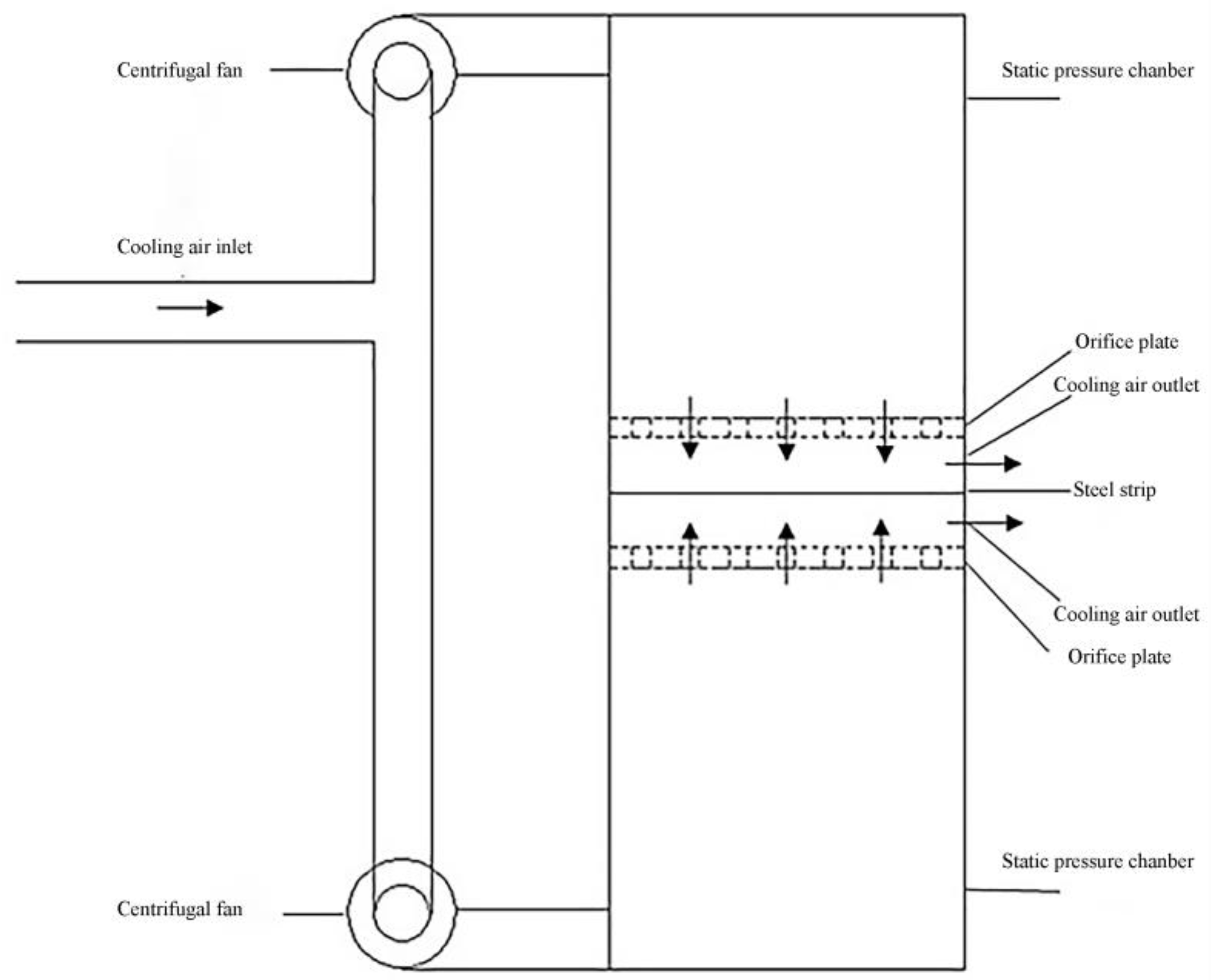
2.1. Building a Physical Model
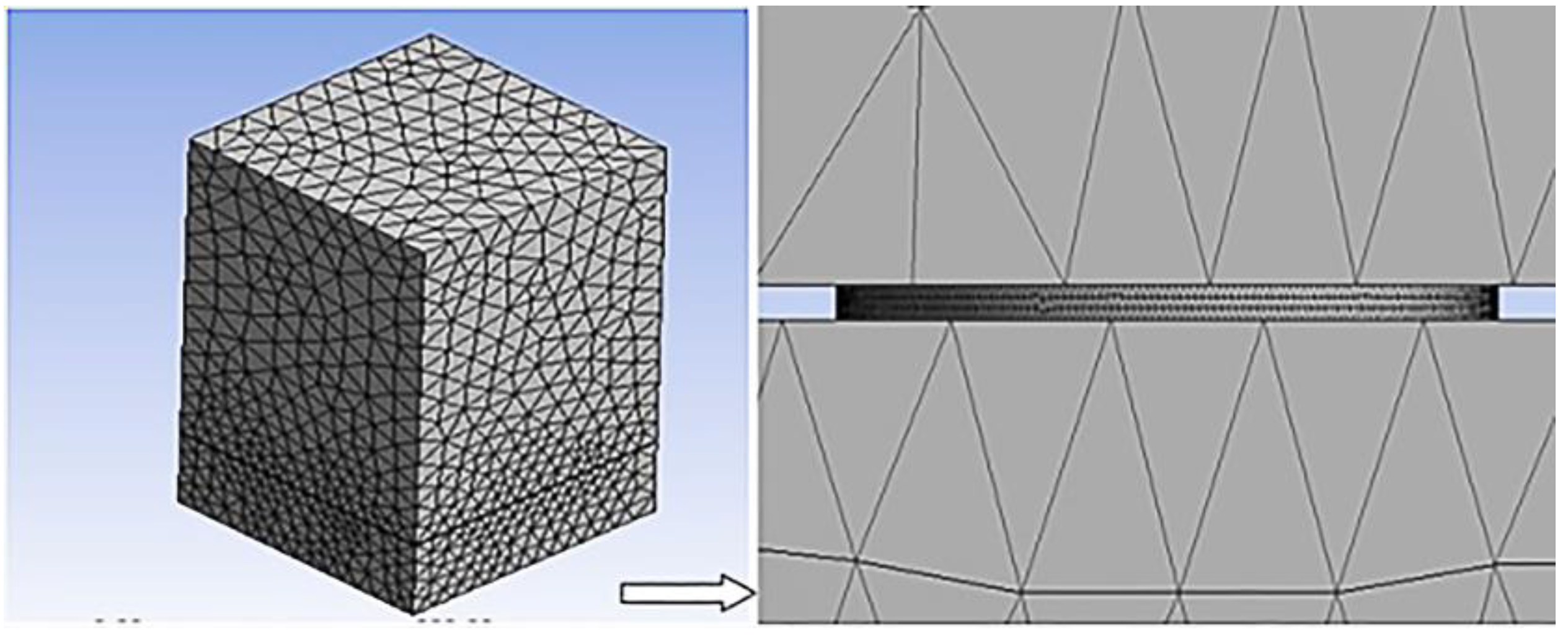
2.2. Grid Division
2.3. Simulation Equations and Boundary Condition Settings
2.4. Definition of Parameters
2.5. Experimental Verification
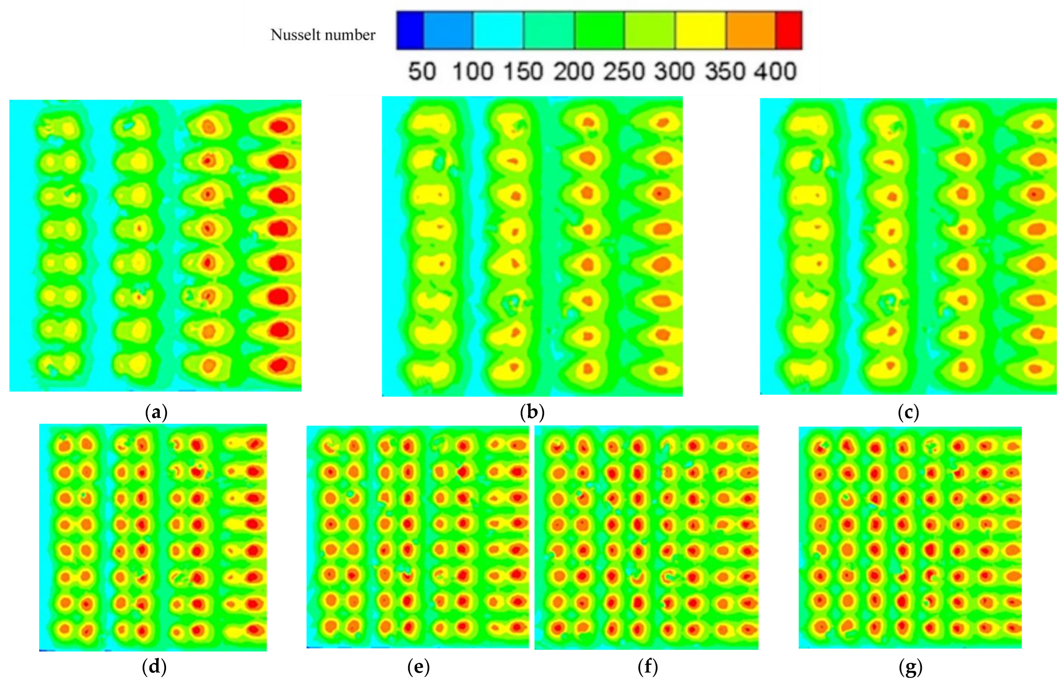
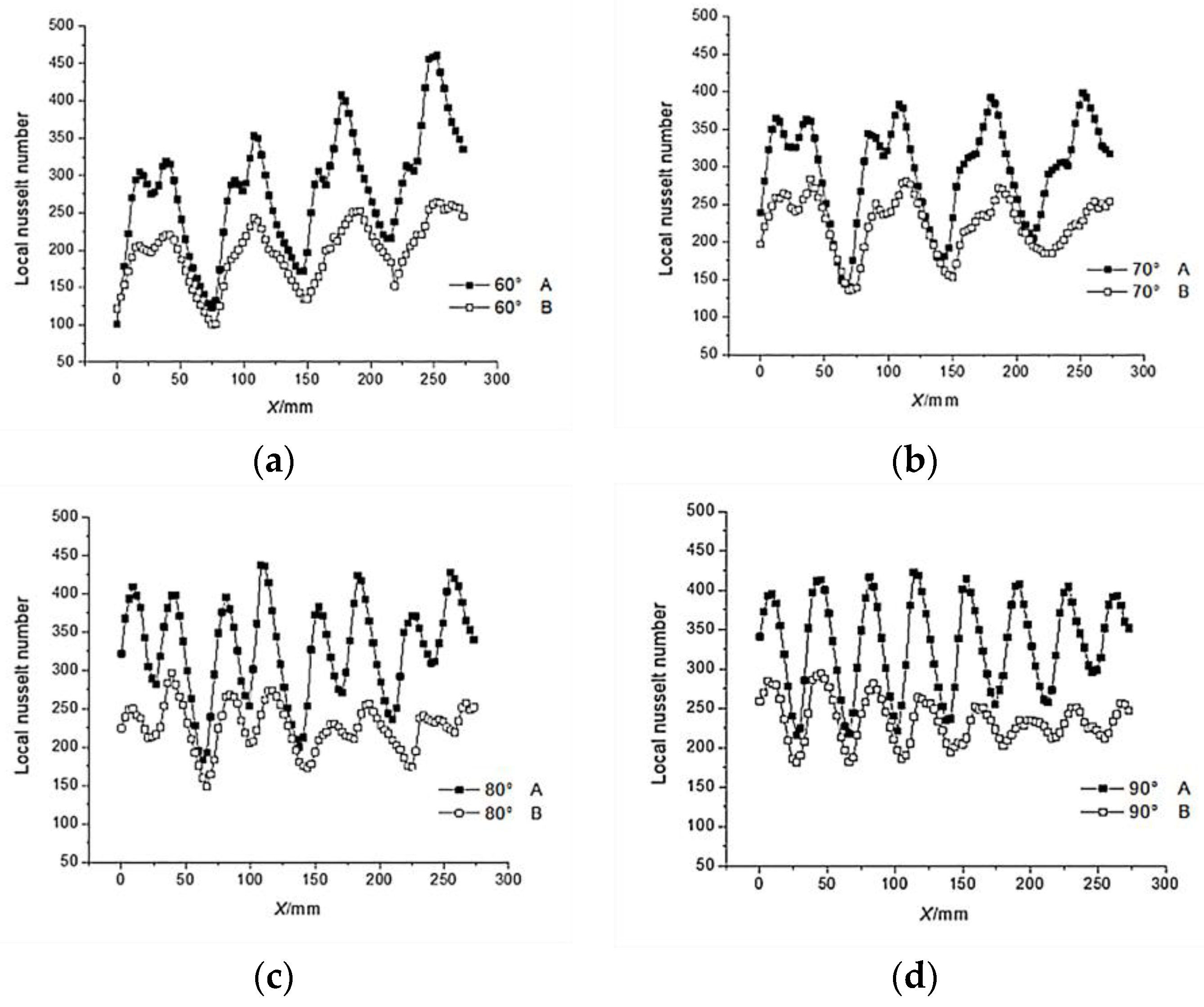
3. Results
4. Discussion
5. Conclusions
- (1)
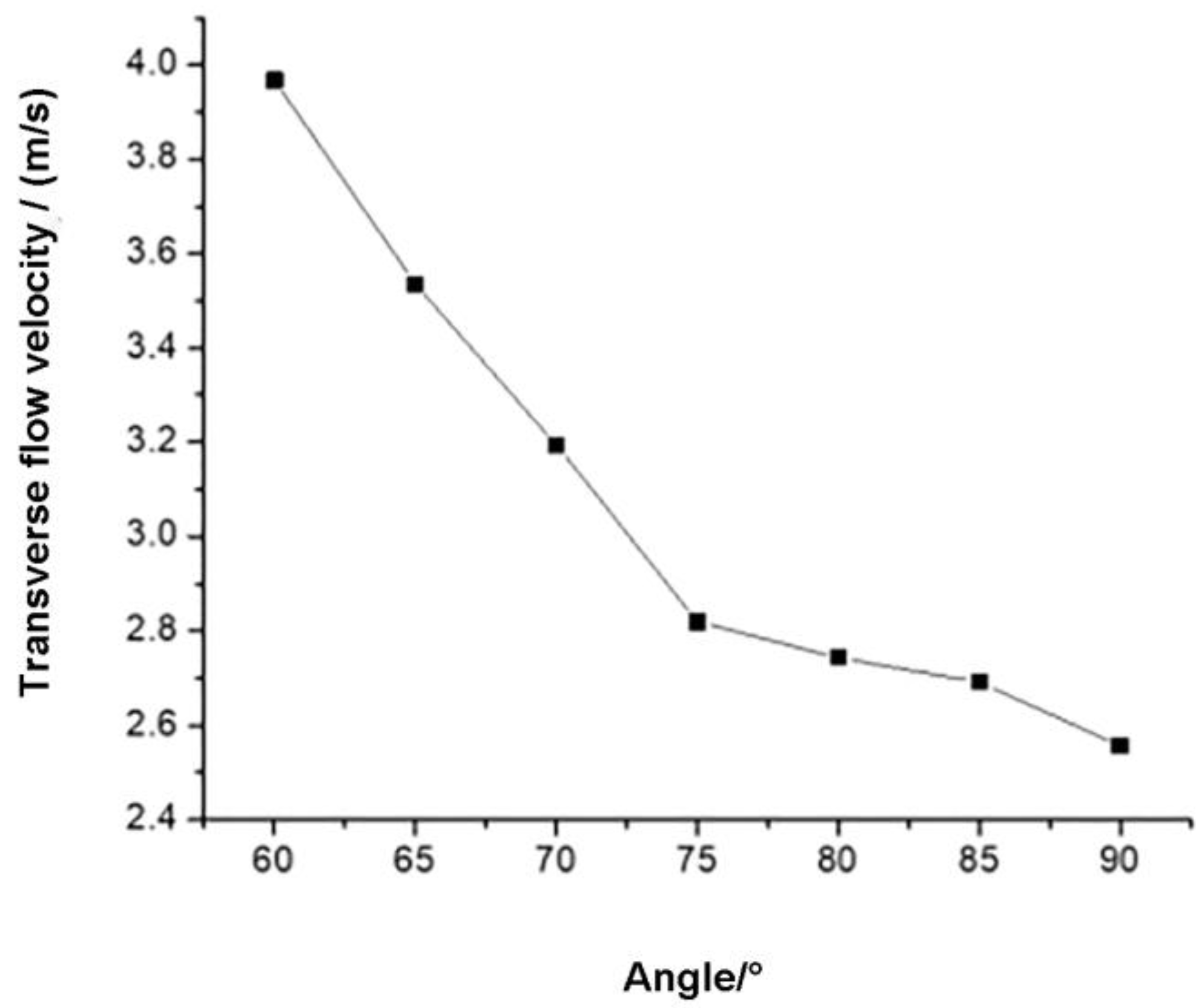
- When θ increases from 60° to 90°, the of the steel strip surface increases from 220.86 to 263.68, an increase of 19.39%. When θ = 90°, the on the surface reaches the maximum, which is conducive to increasing the production capacity of the freezer and reducing energy consumption.
- (2)
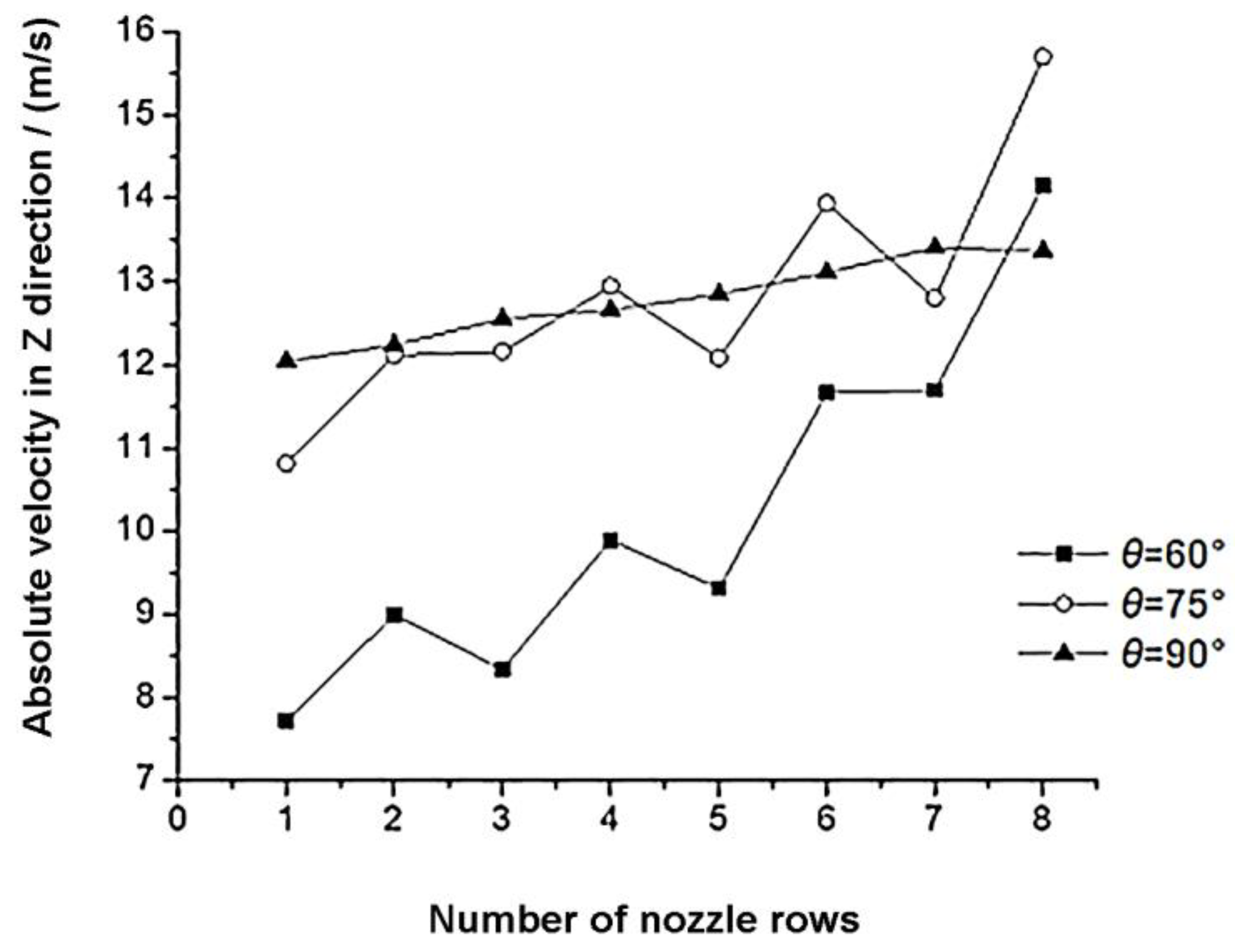
- During the increase of θ from 60° to 90°, the steel strip surface uniformity index η decreases from 0.3075 to 0.2039, a decrease of 33.69%. When θ = 90°, the steel belt surface uniformity index η value reaches the minimum, and the uniformity of heat transfer is the best, which is conducive to improving the quality of frozen food.
- (3)
- In summary, when θ = 90°, which is the optimum angle of inclination of the orifice plate, the steel strip surface average is the largest and the heat transfer uniformity index η value is the smallest.
Author Contributions
Funding
Data Availability Statement
Acknowledgments
Conflicts of Interest
References
- Lee, J.; Lee, S.J. The effect of nozzle configuration on stagnation region heat transfer enhancement of axisymmetric jet impingement. Int. J. Heat Mass Transf. 2000, 43, 3497–3509. [Google Scholar] [CrossRef]
- Ansu, U.; Godi, S.C.; Pattamatta, A.; Balaji, C. Experimental Investigation of the Inlet Condition on Jet Impingement Heat Transfer Using Liquid Crystal Thermography. Exp. Therm. Fluid Sci. 2017, 80, 363–375. [Google Scholar] [CrossRef]
- Carlomngao, G.M.; Ianiro, A. Thermo-fluid-dynamics of submerged jets impinging at short nozzle-to-plate distance: A review. Exp. Therm. Fluid Sci. 2014, 58, 15–35. [Google Scholar]
- Wang, L.; Feng, L.H.; XU, Y.; Xu, Y. Experimental investigation on flow characteristics and unsteady heat transfer of noncircular impinging synthetic jets. Int. J. Heat Mass Transf. 2022, 190, 122760. [Google Scholar] [CrossRef]
- Kim, Y.H.; Lee, D.H.; Han, S.H. Investigation of impingement surface geometry effects on heat transfer in a laminar confined impinging slot jet. Int. J. Heat Mass Transf. 2017, 115, 347–353. [Google Scholar] [CrossRef]
- Tang, Z.G.; Liu, Q.Q.; Li, H.; Min, X.T. Numerical simulation of heat transfer characteristics of jet impingement with a novel single cone heat sink. Appl. Therm. Eng. 2017, 127, 906–914. [Google Scholar] [CrossRef]
- Luo, D.; Wu, J.; Ma, Z.; Tang, P.P.; Liao, X.J. Production of high sensory quality Shiitake mushroom (Lentinus edodes) by pulsed airimpingement jet drying (AID) technique. Food Chem. 2021, 341, 128290. [Google Scholar] [CrossRef] [PubMed]
- Choo, K.; Kang, T.Y.; Kim, S.J. The effect of inclination on impinging jets at small nozzle-to-plate spacing. Int. J. Heat Mass Transf. 2012, 55, 3327–3334. [Google Scholar] [CrossRef]
- Dhrug, L.; Kothadia, H.B.; Kumar, R.A. Investigation of local heat transfer from a flat plate impinged by an inclined circular jet. Int. J. Therm. Sci. 2023, 184, 108027. [Google Scholar]
- Ingole, S.B.; Sundaram, K.K. Experimental average Nusselt number characteristics with inclined non-confined jet impingement of air for cooling application. Exp. Therm. Fluid Sci. 2016, 77, 124–131. [Google Scholar] [CrossRef]
- Attalla, M.; Maghrabie, H.M.; Specht, E. Effect of inclination angle of a pair of air jets on heat transfer into the flat surface. Exp. Therm. Fluid Sci. 2017, 85, 85–94. [Google Scholar] [CrossRef]
- Li, Y.; Li, F.; Tang, J.; Zhang, R.Y.; Wang, Y.F.; Koral, T.; Jiao, Y. Radio frequency tempering uniformity investigation of frozen beef with various shapes and sizes. Innov. Food Sci. Emerg. Technol. 2018, 48, 42–55. [Google Scholar] [CrossRef]
- Li, D.; Zhu, Z.; Sun, D.W. Effects of freezing on cell structure of fresh cellular food materials: A review. Trends Food Sci. Technol. 2018, 75, 46–55. [Google Scholar] [CrossRef]
- Wen, Z.X.; He, Y.L.; Ma, Z. Effects of nozzle arrangement on uniformity of multiple impinging jets heat transfer in a fast cooling simulation device. Comput. Fluids 2018, 164, 83–93. [Google Scholar] [CrossRef]
- Zhao, B.; Tang, W.S.; Wang, Y.P.; Liu, X.Y.; Jin, R.N. Simulation analysis of the effect of oblique jet on the heat transfer characteristics of the wall. Machinery 2022, 49, 1–8. [Google Scholar]
- Xie, J.; Liu, Y.Y.; Wang, J.F. Effects of nozzle structures of air impinging freezer on heat transfer characteristics of steel strip surface. Trans. Chin. Soc. Agric. Eng. 2018, 34, 292–298. [Google Scholar]
- Mao, J.Y.; Si, J.H.; Chen, J.Q.; Li, G.D.; Wang, X.K. Experimental investigation on sand bed scour by an oblique planar water jet at varying impinging angles. Ocean. Eng. 2023, 279, 114526. [Google Scholar] [CrossRef]
- Xu, L.; Jin, L.; Ma, Y.; Gao, J.M.; Li, Y.L. Numerical study on heat transfer by swirling impinging jets issuing from a screw-thread nozzle. Int. J. Heat Mass Transf. 2017, 115, 232–237. [Google Scholar] [CrossRef]
- Guan, T.; Zhang, J.Z.; Shan, Y. Convective heat transfer by a row of tab-excited impinging jets on a wedge-shaped concave surface. Int. J. Therm. Sci. 2016, 100, 37–53. [Google Scholar] [CrossRef]
- Chen, L.; Brakmann, R.; Weigand, B.; Rodriguez, J.; Crawford, M.; Poser, R. Experimental and numerical heat transfer investigation of an impingement jet array with V-ribs on the target plate and on the impingement plate. Int. J. Heat Fluid Flow 2017, 68, 126–138. [Google Scholar] [CrossRef]
- Wang, J.F.; Li, W.J.; Xie, J.; Yang, D.Z.; Liu, Y.Y.; Lu, W.H.; Yang, X.Y. Influence of two nozzle structures on the flow field and heat transfer characteristics of impinging freezer. Food Mach. 2017, 33, 80–85+90. [Google Scholar]
- Zhu, X.W.; Zhu, L.; Zhao, J.Q. An in-depth analysis of conjugate heat transfer process of impingement jet. Int. J. Heat Mass Transf. 2017, 104, 1259–1267. [Google Scholar] [CrossRef]
- Singh, D.; Premachandran, B.; Kohli, S. Effect of nozzle shape on jet impingement heat transfer from a circular cylinder. Int. J. Therm. Sci. 2015, 96, 45–69. [Google Scholar] [CrossRef]
- Li, Y.; Li, B.; Qi, F.S.; Sherman, C.P. Flow and heat transfer of parallel multiple jets obliquely impinging on a flat surface. Appl. Therm. Eng. 2018, 133, 588–603. [Google Scholar] [CrossRef]
- Hou, Y.; Tao, Y.; Huai, X.L.; Zou, Y.; Sun, D.L. Numerical simulation of multi-nozzle spray cooling heat transfer. Int. J. Therm. Sci. 2018, 125, 81–88. [Google Scholar] [CrossRef]
- Rahman, M.M.; Liu, W.C.; Lv, M.; Pan, H.C. Exploring SIMPLE algorithm for all speeds. Ain Shams Eng. J. 2023, 14, 101854. [Google Scholar] [CrossRef]
- Attalla, M.; Maghrabie, H.M.; Qayyum, A.; Adnan, G.; Specht, E. Influence of the nozzle shape on heat transfer uniformity for in-line array of impinging air jets. Appl. Therm. Eng. 2017, 120, 160–169. [Google Scholar] [CrossRef]
- Li, H.H.; Chen, H.Y.; Cui, Z.W. Numerical simulation on effect of tip clearance between screw flight and barrel on performance of food melt conveying section in single screw extruder for expanding. Food Mach. 2016, 32, 68–72+76. [Google Scholar]
- Subasi, A.; Sahin, B.; Kaymaz, I. Multi-objective optimization of a honeycomb heat sink using Response Surface Method. Int. J. Heat Mass Transf. 2016, 101, 295–302. [Google Scholar] [CrossRef]
- Ma, C.; Yan, C.; Cao, X.W.; Wen, Z.X.; He, Y.L. Numerical study of the heat transfer uniformity problem of an array of air jets. J. Eng. Thermophys. 2016, 37, 2378–2384. [Google Scholar]
- Chen, L.Q.; Zhang, D.; Chen, W.W. Numerical simulation and experiments of two-phase flow in splitter gears based on fluid-solid coupling. Trans. Chin. Soc. Agric. Eng. 2014, 30, 54–61. [Google Scholar]
- Zhang, Z.; Xie, J. Numerical simulation of the flow and temperature fields in a quick-freezing unit with upper and lower air-vented plates. J. Refrig. 2009, 30, 36–40. [Google Scholar]
- Barewar, S.D.; Joshi, M.; Sharma, P.O.; Kalos, P.S.; Bakthavatchalam, B.; Chougule, S.S.; Habib, K.; Saha, S.K. Optimization of jet impingement heat transfer: Optimization of jet impingement heat transfer: A review on advanced techniques and parameters. Therm. Sci. Eng. Prog. 2023, 39, 101697. [Google Scholar] [CrossRef]
- Nuntadusit, C.; Wae-Hayee, M.; Tekasakul, P.; Eiamsaard, S. Local heat transfer characteristics of array impinging jets from elongated orifices. Int. Commun. Heat Mass Transf. 2012, 39, 1154–1164. [Google Scholar] [CrossRef]
- Katti, V.; Prabhu, S.V. Influence of streamwise pitch on local heat transfer distribution for in-line arrays of circular jets with spent air flow in two opposite directions. Exp. Heat Transf. 2009, 22, 228–256. [Google Scholar] [CrossRef]


Disclaimer/Publisher’s Note: The statements, opinions and data contained in all publications are solely those of the individual author(s) and contributor(s) and not of MDPI and/or the editor(s). MDPI and/or the editor(s) disclaim responsibility for any injury to people or property resulting from any ideas, methods, instructions or products referred to in the content. |
© 2023 by the authors. Licensee MDPI, Basel, Switzerland. This article is an open access article distributed under the terms and conditions of the Creative Commons Attribution (CC BY) license (https://creativecommons.org/licenses/by/4.0/).
Share and Cite
Xie, J.; Luo, X.; Wang, J.; Liu, Y. Effect of Inclined Orifice in Air Impingement Freezer on Heat Transfer Characteristics of Steel Strip Surface. Processes 2023, 11, 2410. https://doi.org/10.3390/pr11082410
Xie J, Luo X, Wang J, Liu Y. Effect of Inclined Orifice in Air Impingement Freezer on Heat Transfer Characteristics of Steel Strip Surface. Processes. 2023; 11(8):2410. https://doi.org/10.3390/pr11082410
Chicago/Turabian StyleXie, Jing, Xilan Luo, Jinfeng Wang, and Yuyan Liu. 2023. "Effect of Inclined Orifice in Air Impingement Freezer on Heat Transfer Characteristics of Steel Strip Surface" Processes 11, no. 8: 2410. https://doi.org/10.3390/pr11082410
APA StyleXie, J., Luo, X., Wang, J., & Liu, Y. (2023). Effect of Inclined Orifice in Air Impingement Freezer on Heat Transfer Characteristics of Steel Strip Surface. Processes, 11(8), 2410. https://doi.org/10.3390/pr11082410