Article

The Law of Gas–Liquid Shear Mixing under the Synergistic Effect of Jet Stirring

State Key Laboratory of Mining Response and Disaster Prevention and Control in Deep Coal Mines, College of Materials Science and Engineering, Anhui University of Science and Technology, Huainan 232001, China
*
Author to whom correspondence should be addressed.
Processes 2023, 11(9), 2531; https://doi.org/10.3390/pr11092531
Submission received: 18 July 2023 / Revised: 20 August 2023 / Accepted: 21 August 2023 / Published: 23 August 2023

Abstract

:
At present, there is a common problem that the mixing mode is single and it is difficult to overcome the inherent bottleneck of multiphase mixing. A mixing device combining the advantages of jet entrainment and mixing dispersion was designed and built. In an effort to determine the mixing degree of two phases, the mixing coefficient of gas–liquid charging was measured using the cylinder method with the optimal working parameters. To explore the optimization of the mixing conditions and control mechanism of multiphase materials, the law of gas–liquid shear mixing in the process of multi-force field synergistic change was revealed. Based on the testing of the gas injection capacity under different working conditions and the calculation of the gas–liquid two-phase mixing coefficient, it was concluded that the flow rate was the direct key factor affecting the gas injection capacity. The working speed also had a certain impact on the gas injection capacity. When working at a high speed and high flow rate, the jet beam broke through the cutting barrier and presented a superposition effect. The jet impact assisted the rotation, and the suction performance of the device was significantly improved, which was conducive to the mixing of the gas and liquid phases. According to the test results of the measuring cylinder method, the calculated average inflation volume is 0.01 m 3 / ( m 2 · m i n ) , the inflation uniformity coefficient is 77.51, and the mixing coefficient of the gas and liquid phases is 0.12.

1. Introduction

Two-phase and multiphase mixing are widely present in natural and chemical industrial processes, including pharmaceuticals, food, metallurgy, pharmaceuticals, mining, petroleum, and natural gas [1,2,3,4]. As mentioned by Zhang [5], in the complex petroleum industry, liquid–solid, gas–liquid, and liquid–liquid interfaces dominate, bringing many challenges. The mixing of different systems in nature is to pursue uniformity of mixing and achieve equilibrium points. The mixing in the chemical industry is to optimize the reaction process and reduce the time required for materials to participate in the chemical reaction [6]. The mixing of multiphase materials plays an important role in the chemical process flow. The materials can improve the uniformity of the internal reaction system by mixing to increase the reaction contact area and change the physical and chemical properties of the reaction materials, so as to meet the requirements of chemical production [7,8]. Full mixing of substances is a prerequisite for many chemical reactions, as well as a process requirement. Some physical changes also require a mixing operation to achieve the effect, such as gas absorption and liquid extraction. As an important carrier for mixing in the chemical industry, the kettle reactor carries the mixing tasks of different types and different interphase materials such as liquid mixing, solid–liquid mixing, gas dispersion in the liquid, enhanced heat and mass transfer, and chemical reaction [9,10,11,12,13].
Jet is widely used in ore cutting, metal polishing, farmland irrigation, etc., due to its low energy consumption and strong adaptability, and is constantly expanding into new application fields [14,15,16]. The material is suspended in the liquid to form a mixture or suspension by means of the stirring action of a paddle. The main purpose is to make the material fully and evenly dispersed in the liquid medium, and finally, strengthen the reaction process by the mixing [17,18,19,20,21,22,23]. There are many types of kettle reactors in the chemical industry, and their structure and appearance are not uniform. Based on the phase differences of the reaction materials, they can be divided into homogeneous reactors and heterogeneous reactors [24]. The more common ones are solid–liquid, liquid–liquid, gas–liquid reactors, and gas–liquid–solid three-phase reactors. However, the traditional mechanical stirring reactor is widely used, which mainly consists of two core components: the stirrer and the reactor body. The traditional method of using direct gas supply is not conducive to the full mixing of gas and liquid phases, reducing the utilization rate of the gas and causing impurities that damage the chemical properties of the prepared products. Moreover, the production cost of the equipment is high, which is not conducive to maintenance and upkeep [25,26,27,28].
Therefore, based on the advantages of jet and mixing, the gas–liquid two-phase mixing process was taken as the starting point. Based on the working mode of the traditional stirring kettle and the new jet mixing technology, a new semi-industrial multiphase mixing device was proposed: a multiphase material mixing device with jet and mixing synergy. The research objective is to explore the optimization of three-phase material mixing conditions under the synergistic effect of jet and stirring in depth.
(1) The response mechanism of the jet structure and functional parameters affecting jet suction and the impact of a negative pressure environment and suction volume is studied. In this experiment, a semi-industrial experimental device was built to explore the law of gas phase and liquid shear suction under different working conditions.
(2) Exploring the shear effect on the gas phase and the dispersion effect on solid materials at different rotational speeds in order to determine the suspension and dispersion behavior of the device on solid particles. Identifying the optimal working parameters to reveal the dispersion mechanism of the stirring effect on the solid phase. Mastering the mixing mechanism of three-phase materials under the action of jet and stirring; identifying the optimal working parameters of jet and stirring; enriching existing basic theories; and providing a theoretical reference and technical basis for economic industrial production. Because it has important research value and significance.

2. Materials and Methods

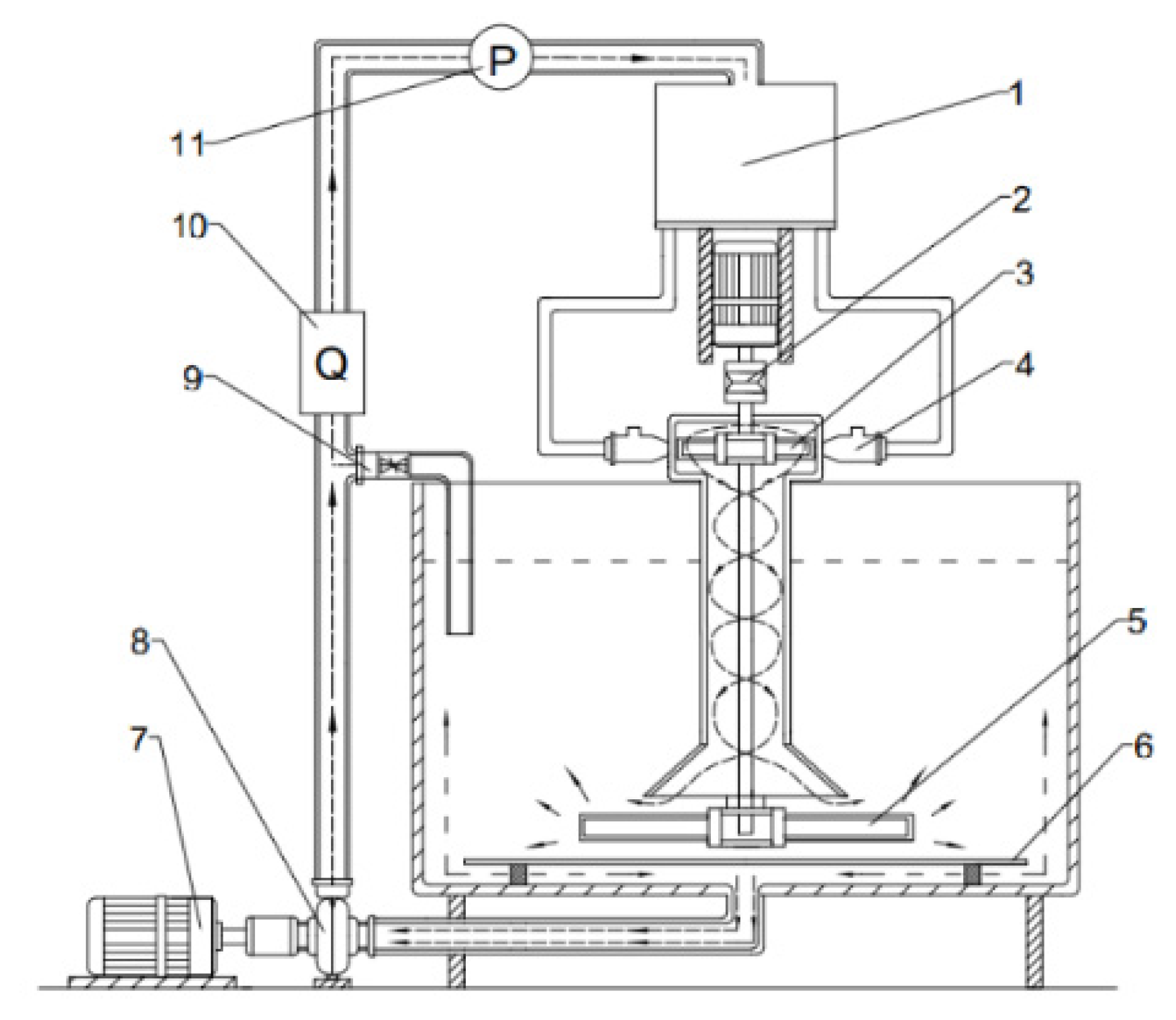
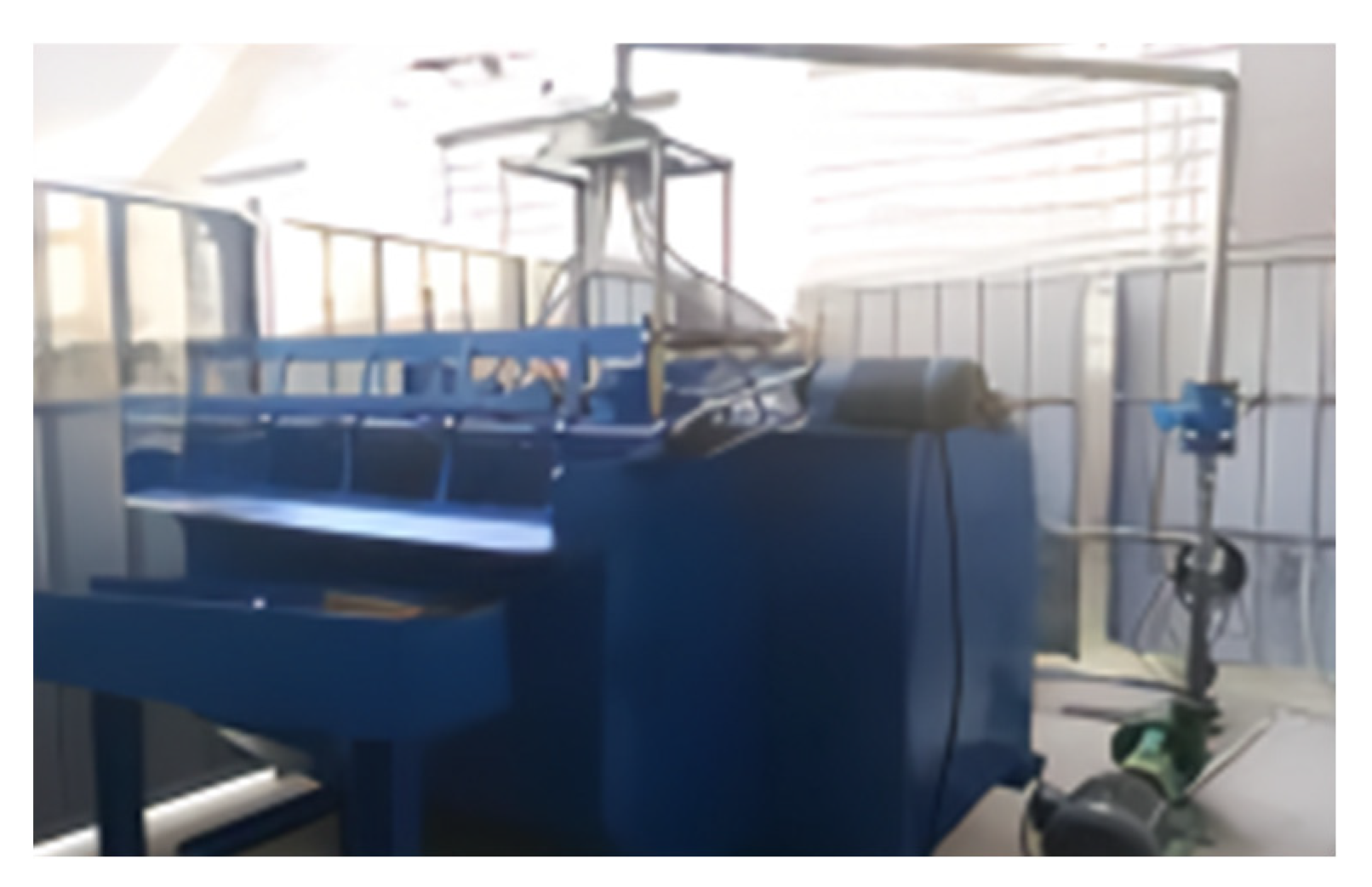
2.1. Experimental Setup

The determination of the working parameters of the jet nozzle was based on the Bernoulli characteristic equation calculation and an extensive reference literature search. It was found that the negative pressure formed by the vacuum inside the nozzle was directly proportional to the flow rate of the feed, that is, the flow rate of the feed affected the negative pressure and, thus, the suction amount. In the process of gas–liquid two-phase mixing, air intake is a prerequisite, and the flow rate and pressure of the feed are the most critical factors for gas–liquid two-phase mixing, which have also been widely studied. In order to facilitate the study of the influence of the feed flow rate and pressure on the suction capacity, the optimized parameter values in the relevant jet literature were selected to fix the structural parameters of the jet nozzle and create an experimental model. Based on the variable parameter feed flow rate and pressure as experimental parameters, we explored the suction volume and the mixing of two and three phases. The selection values of the structural parameters for the jet nozzle model are shown in Table 1.
According to the working characteristics of the nozzle jet, the diffusion phenomenon of fluid sprayed through the nozzle can lead to a decrease in the impact capacity. This results in a loss in jet kinetic energy. To reduce energy consumption, the nozzle should be applied closely to the impeller. Only by fully utilizing the high impact kinetic energy of the jet can high energy utilization and conversion be achieved.
This was calculated based on the design principles and relevant empirical formulae. Based on practical experience, the structural parameters of the main components of the processing fluidics and stirring devices are shown in Table 2.
Figure 1 is a structural diagram of the self-made jet stirring device. The circulating-pump-pressurized suction mixing system is transported to the jet nozzle through the pipeline. Due to the ejection, the gas is sucked into the nozzle and mixed shear with the jet liquid. The impeller is assisted in rotation under the impact of the jet beam, thus improving the utilization rate of energy. The energy conversion rate depends on the impact force generated by the jet beam impacting the impeller. The gas–liquid two-phase mixed system presents a spiral descent in the guide tube and collides with the bottom impeller. The shear action of the impeller changes the suspension characteristics of the mixed system, making the gas and liquid phases fully mixed in the tank. The physical image created by the research and design institute is shown in Figure 2.

2.2. Experimental Method

The variable frequency control system is connected to the circulating pump motor and the mixing motor. The variable frequency control system is debugged to display the equipment’s working condition and working speed.
The LZD-F-B electromagnetic flowmeter is installed above the delivery pipeline of the circulating pump. It connects the power line, dedicated signal line, and dedicated excitation line of the sensor to the electromagnetic flowmeter to measure the flow rate and flow rate in the pipeline. The LZB series glass rotor flowmeter is sealed and connected to the suction port of the nozzle. The working condition of the rotor is measured and recorded to determine the gas injection capacity and negative pressure inside the nozzle. The percentage of gas volume to liquid flow rate ratio is calculated, as well as the difference in gas to liquid velocity, based on parameters such as flow rate. Based on the negative pressure environment inside the nozzle, the mixing effect of the two-phase gas–liquid mixture can be determined.
To explore the influence of flow rate and speed-related factors on the gas ejection capacity of the device, a suction volume test was carried out. The mixing motor was set in the control system to work at different speeds of 75, 150, 225, 300, 375, 450, and 525 r/min, and the flow in the pipeline was adjusted to 7.6, 7.8, 8.0, 8.2, 8.4, and 8.6 m3/h using the diverter valve on the device under the same working speed. The glass rotor flowmeter of the LZB series was sealed and connected to the suction end of the nozzle of the device to record the flow and velocity of the LZD-F-B electromagnetic flowmeter, and record the suction value of the dependent variable according to the rotor position of the glass rotor flowmeter.
In an effort to determine the mixing degree of the two phases, the mixing coefficient of gas–liquid charging was measured by the cylinder method with the optimal working parameters. In the plane of the tank, 12 measuring points were evenly selected with the spindle as the center of symmetry according to the principle of symmetry, and each measuring point was measured three times. The cross-sectional area of the transparent measuring cylinder should be greater than 18 cm2, and a stopwatch should be used to record the time required for the discharge of 250 cm3 water. The sealing property of the cylinder should be maintained during measurement, and the measuring cylinder should be vertically inserted 120 mm below the liquid level, as shown in Figure 3.

3. Results and Discussion

The prerequisite of mixing is to ensure a good gas ejection ability. Only by ensuring sufficient gas to participate in the mixing reaction can the mixing degree of the gas and liquid phases be improved.

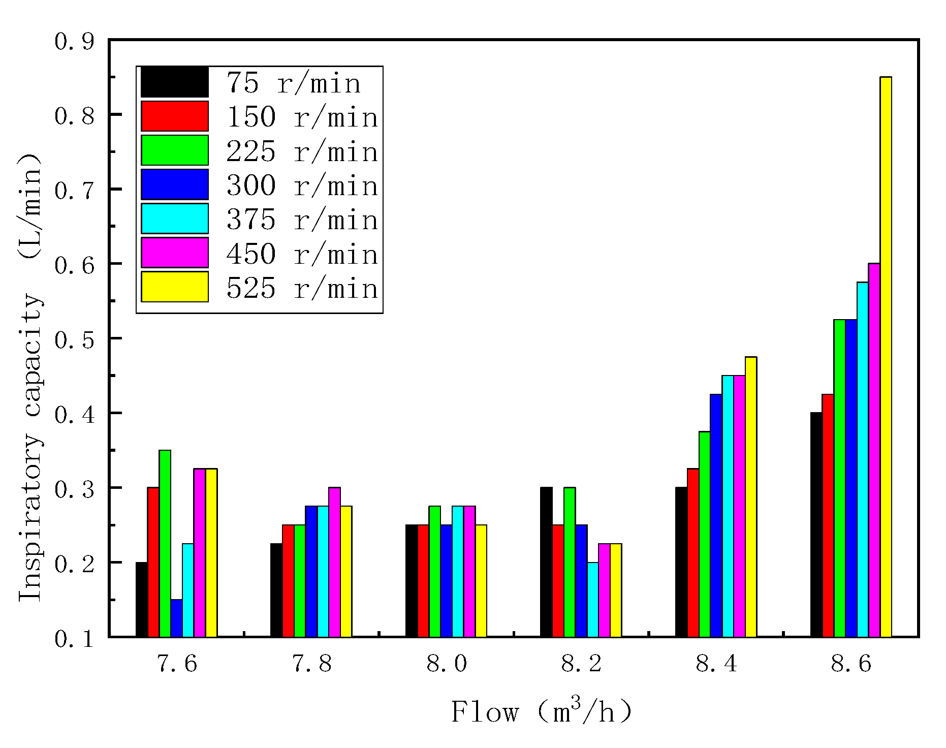
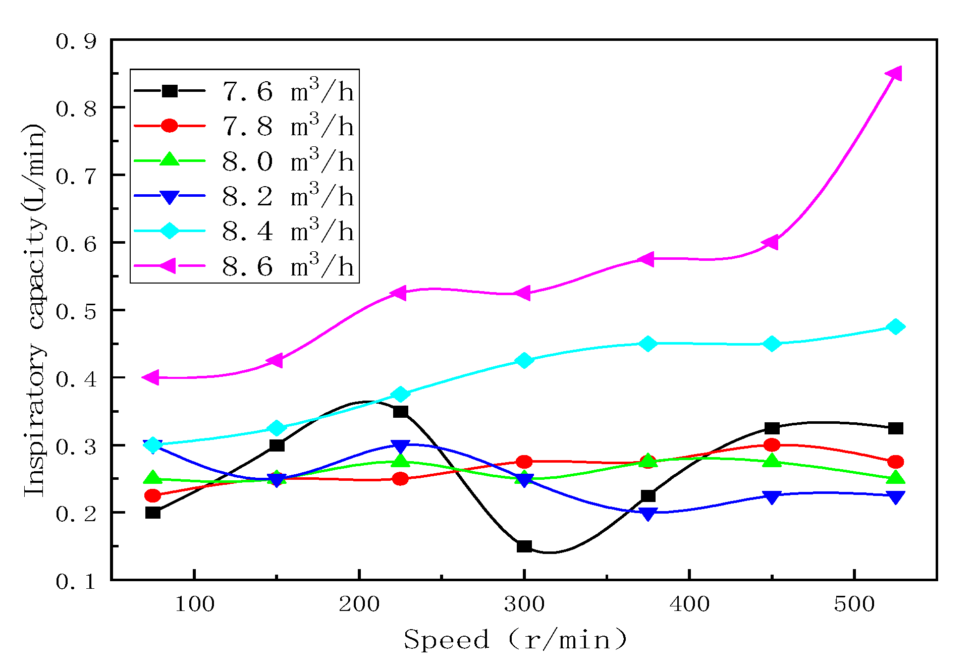
3.1. Injection Ability Test

Figure 4 shows the inspiratory volume of the device under different flow rates. It can be seen from the figure that when the flow rate is less than 8.2 m3/h, the change trend in the inspiratory volume of gas is not obvious, and when the flow rate is greater than 8.2 m3/h, the inspiratory volume of gas is significantly improved. It is shown that increasing the liquid flow rate can increase the intake of gas, and the flow rate is the direct key factor to change the ejection ability of the gas.
It can be clearly observed from Figure 5 that at higher flow rates of 8.4 and 8.6 m3/h, the gas ejection capacity increases with the increase in rotational speed, and when the rotational speed is higher than 300 r/min, the suction capacity increases. The low flow rates, especially the comparison between 525 r/min and 75 r/min, show a significant change in inspiratory performance, the inspiratory capacity of the slightly higher flow rate is the minimum, but the inspiratory capacity of the lowest flow rate is the maximum. Thus, it is verified that the rotational speed also affects the ejection ability of gas. A high rotational speed will affect the suction performance at low flow rates, bring negative effects to the nozzle and reduce the gas ejection ability, thus affecting the gas–liquid two-phase mixing effect.
In order to study the mutual influence of flow rate and speed, the interactive influence of flow rate and speed is analyzed. As shown in Figure 6, when the rotational speed is less than 300 r/min, with the increase in the flow rate, the trend of the suction capacity curve at each rotational speed is roughly the same, and the suction capacity gradually increases with the increase in the flow rate. When the rotation speed is higher than 300 r/min, the curve changes in a highly consistent trend. The curve in the later stage presents a steep rise, and the suction performance increases significantly.
In general, the flow rate is the direct key factor, while speed has a certain influence. When the working speed is high, the jet beam is cut by the impeller at a low flow rate, which obstructs the movement of the fluid. The reaction generated by the jet impact makes the fluid accumulate in the nozzle of the device, affecting its inspiratory performance, bringing negative effects and reducing the gas ejection ability. With a high speed and high flow rate, the superposition effect is presented and the jet beam breaks through the cutting barrier, the jet impact assists rotation, and the suction performance of the device is significantly improved, which is conducive to the mixing of the gas and liquid phases.

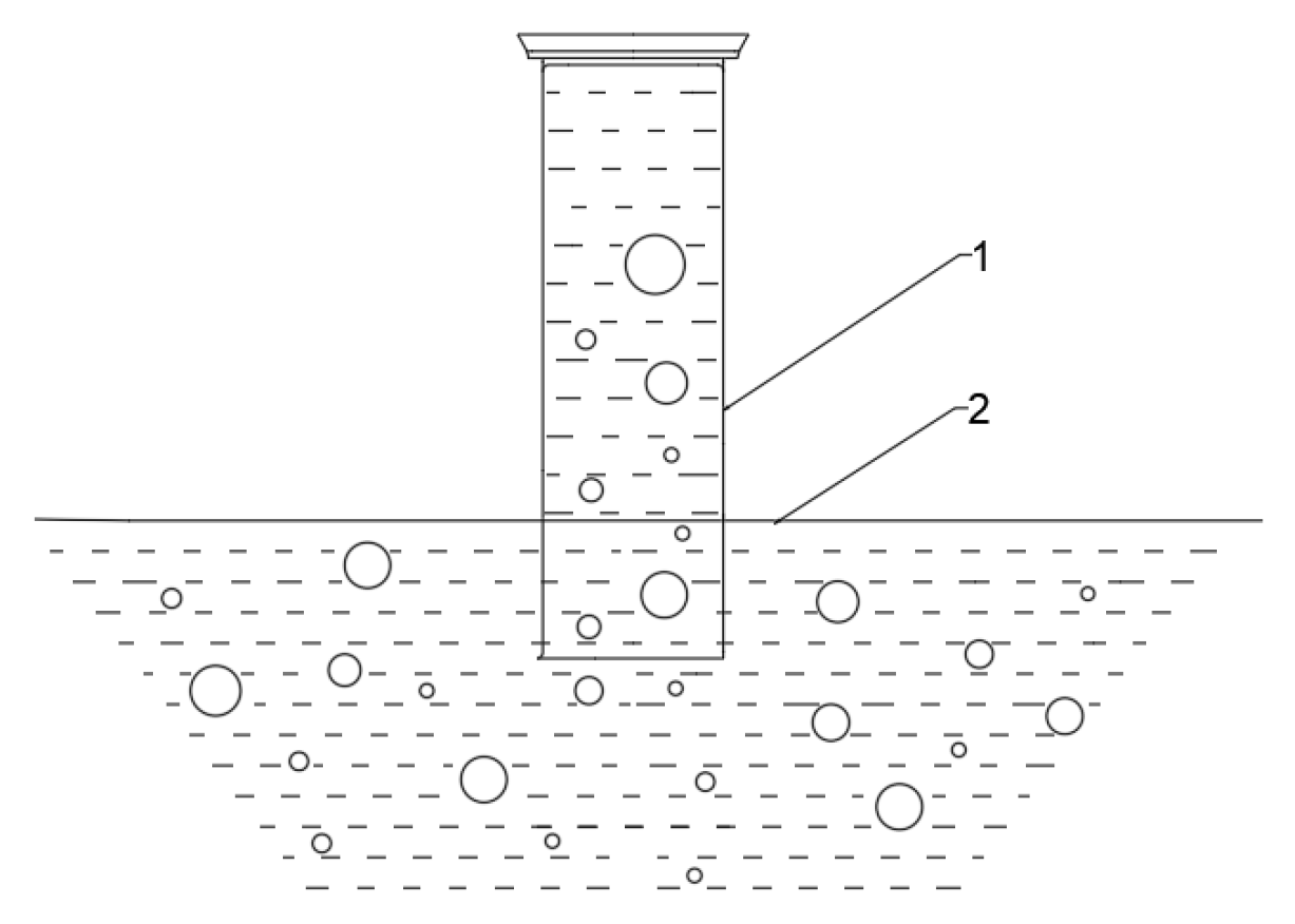
3.2. Gas–Liquid Shear Mixing

For the variable flow field, it is difficult to specify the migration, movement, dispersion, and mixing of different phase materials. The change in ejection capacity under the synergistic actions of jet and stirring indicated that the flow rate and rotation speed had certain influences on the gas–liquid two-phase shear mixing. The flow rate of the liquid in the device increased with the increase in flow rate, and the difficulty of increasing the liquid flow rate was greater than that of the gas. The difference between the gas velocity and liquid velocity was used to explore the gas–liquid two-phase shear condition.
It can be seen from Figure 7 that at a low flow rate, before the turning point of 8.2 m3/h, the gas–liquid velocity difference fluctuates up and down in a stable range. This is similar to the impact of the flow rate on the gas ejection capacity. When the flow rate is high, after the turning point of 8.2 m3/h, the gas–liquid velocity difference of each group changes obviously and shows a decreasing trend in numerical terms. With the increase in flow velocity, the increase in gas velocity decreases the difference of the gas–liquid velocity, shortens the gap with the flow velocity of jet liquid, and enhances the shear degree of the two-phase gas–liquid mixture.
Similar to the flow rate difference, when the operating parameters change, the gas intake also changes. The ratio percentage of gas volume to liquid flow rate is used to describe the mixing of two phases in the change in working parameters. As can be seen from Figure 8, the gas–liquid ratio mostly increases with the increase in flow rate at a low rotation speed, while the gas–liquid ratio decreases firstly and then increases with the increase in flow rate at a high rotation speed, showing a “V-shaped” trend. The appearance of this “V” shape is not conducive to the mixing of gas–liquid two-phase materials. It also makes the energy utilization rate low, consumes a lot of energy, and reduces the mixing probability of two-phase materials. The working conditions at the top of the “V” should be avoided during production and testing.
The glass rotor flowmeter can directly measure the suction volume of the device. It is convenient to use and easy to operate, but cannot reflect the actual amount of gas involved in the reaction. In order to specifically represent the mixing situation between multiple phases, the gas–liquid two-phase mixing degree of the device was evaluated by using the gas–liquid mixing coefficient in the gas–liquid mixing of the MTT 652-1997 Chinese standard [29].
According to Table 3, the improved and optimized mixing coefficient can be calculated using a formula to evaluate the mixing degree of gas–liquid two-phase flow. The calculation results and formula are as follows:
Calculate the inflation rate at each measurement point according to Equation (1):
Q i = 0.6 V A 1 t
Q i —the inflation rate at the i-th measurement point, m3/(m2∙min);
V—volume of clean water discharged from the measuring cylinder, cm3;
A1—cross-sectional area of the measuring cylinder, cm2;
T—time required to discharge a specified volume of clean water from the measuring cylinder, s.
The volume of discharged clean water is 250 cm3, and the cross-sectional area of the cylinder is 19.63 cm2.
Calculate the average inflation rate of the tank according to Equation (2):
Q ¯ = 1 n i = 1 n Q i
Q —the inflation rate at each measurement point, m3/(m2∙min);
N —number of measuring points;
Q—the average inflation rate of the device tank.
Calculation of inflation uniformity coefficient:
Calculate the inflation uniformity coefficient of the tank according to Equation (3):
K = 100 ( 1 1 n Q ¯ i = 1 n Q i Q ¯ )
K —inflation uniformity coefficient, %.
Calculation of inflation mixing coefficient:
The gas–liquid mixing coefficient is calculated according to Equation (4):
β = 60 Q ¯ A 2 q v
β —mixing coefficient;
Q ¯ —inflation uniformity coefficient of the entire machine, m3/(m2∙min);
A 2 —area of the tank, m2;
q v —measured flow rate of the flowmeter, m3/h.
The mixing coefficient of two phases of gas can be calculated to evaluate the mixing of two phases of gas and liquid. The calculation results are as follows: the average filling capacity of the device is 0.01 m3/(m2∙min), the uniform coefficient of filling is 77.51, and the mixing coefficient of the gas–liquid phase is 0.12. The degree of gas–liquid mixing still needs to be further improved.

3.3. Disscussion

In these expriments, the mixing characteristics of each phase in the mixing process of multiphase materials were studied, and a semi-industrial multiphase material mixing device based on jet mixing was used as the test object. The influence factors and mixing rules of the material mixing were determined through a theoretical analysis and experiment, and the mixing conditions were optimized. However, the significance of fitting engineering research needs to be further studied when it is transformed into industrial production equipment. Among areas for further study are:
(1)
Under the synergetic action of jet mixing, the impact of the jet beam drives the impeller to assist in rotation. It is necessary to explore the interaction between the jet and mixing in order to improve the energy conversion rate. The critical condition of the impeller cutting the jet beam is explored to avoid the negative feedback effect and improve the energy conversion.
(2)
The centrifugal effect of solid materials caused by a high working speed, the specific representation of the centrifugal situation and centrifugal force of materials, and the influence of particle size and the density of materials on the suspension effect need to be further explored. Thus, it is helpful to study the flow field movement law in the tank and explore the migration law and dispersion of materials.
(3)
In this experimental study, no in-depth exploration was conducted on the environmental factors of equipment and materials. Although the experimental environment conditions were stable, in chemical production, materials will be at different working temperatures. Temperature can also affect the degree of mixing and other aspects, which requires further consideration.

4. Conclusions

  • Flow rate is the key factor affecting gas ejection ability, and rotational speed has a certain effect. The interaction between flow rate and speed make the impeller at high speed cut the jet beam at a low flow rate, causing a negative effect and reducing the suction capacity. At high speeds and high flow rates there is a superimposed effect that enhances the suction effect.
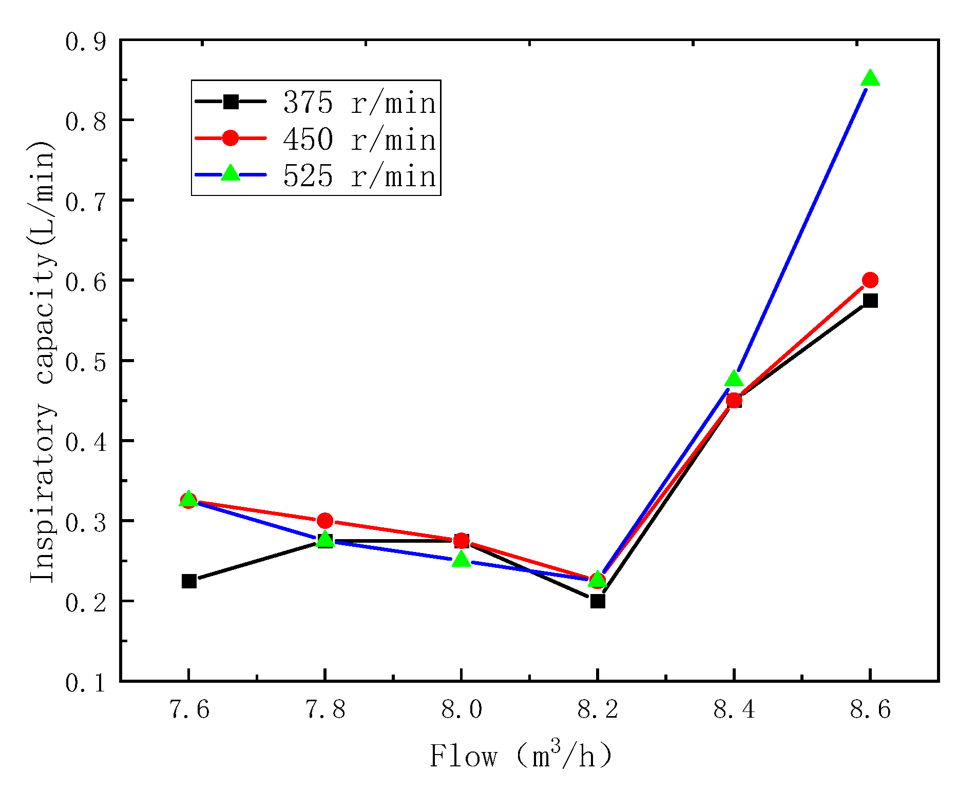
  • When the flow rate increases to 8.2 m3/h, the gas–liquid shear mixing is enhanced.
    The velocity difference between the gas and the liquid represents the shear condition of the gas–liquid phase. When the flow rate is before the turning point of 8.2 m3/h, the difference is relatively stable; when it is after the turning point, the difference decreases significantly and the degree of gas shear is strengthened.
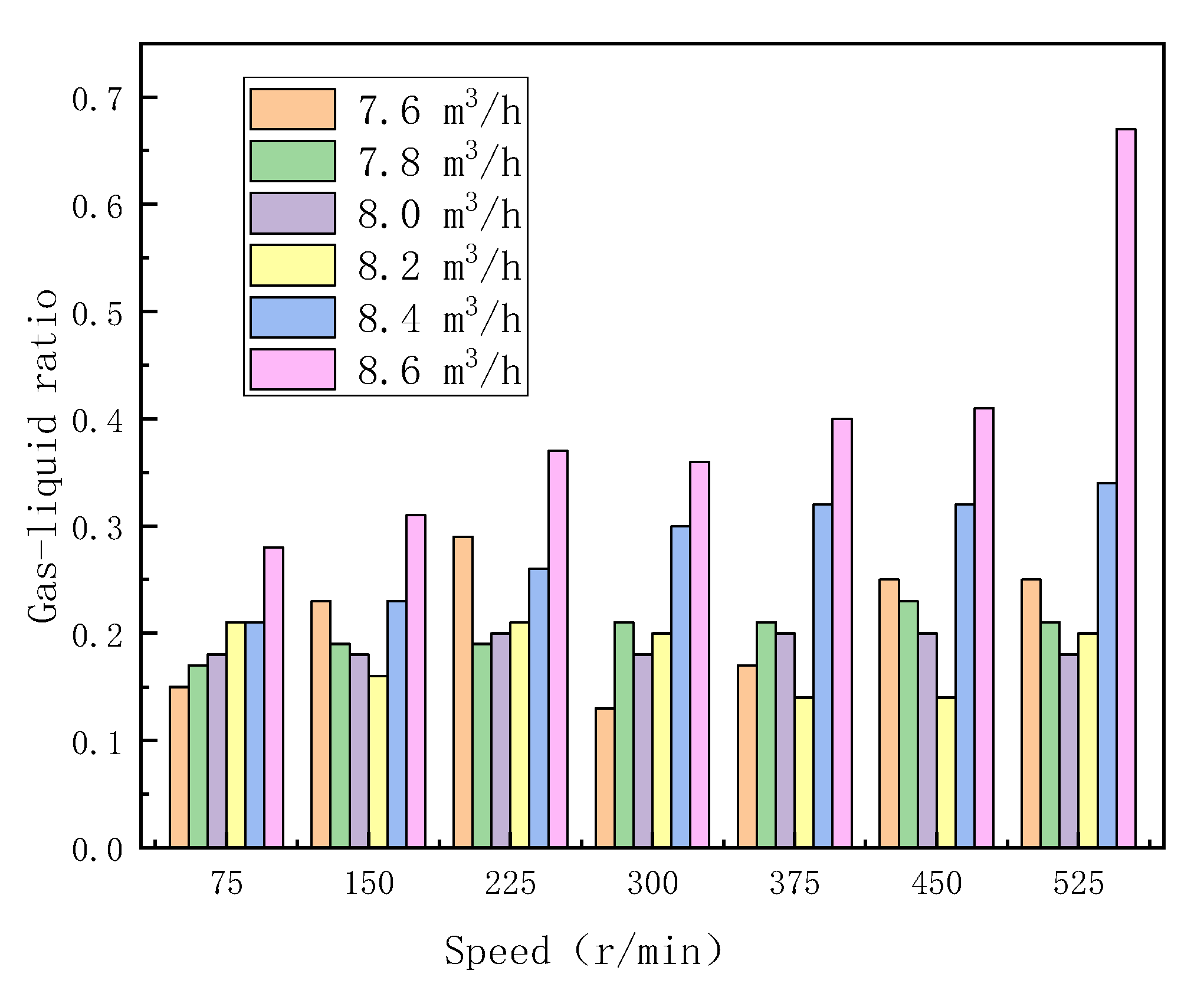
  • The mixing degree was evaluated by the ratio percentage of gas volume to liquid flow and the mixing coefficient. At a high rotational speed, the gas–liquid ratio shows a V-shaped trend, and the top angle condition is not conducive to the mixing of the two phases. The coefficients of gas–liquid two-phase mixing are calculated: the average filling volume is 0.01 m3/ (m3∙min), the uniform coefficient of filling is 77.51, and the mixing coefficient of the two-phase gas–liquid is 0.12.

Author Contributions

Conceptualization, W.Z. and J.Z.; methodology, W.Z.; software, L.L.; validation, W.Z., L.L. and L.W.; formal analysis, H.W.; investigation, L.L.; resources, W.Z.; data curation, W.Z.; writing—original draft preparation, W.Z.; writing—review and editing, C.C.; supervision, W.Z. and J.Z.; project administration, W.Z.; funding acquisition, W.Z. All authors have read and agreed to the published version of the manuscript.

Funding

This research is supported by the University Scientific Research Project of The Education Department of Anhui Province (KJ2021A0429), the University Excellent Talents Training Funding Project of the Education Department of Anhui Province (gxyqZD2021109), the Open Foundation of State Key Laboratory of Mining Response and Disaster Prevention and Control in Deep Coal Mines (SKLMRDPC19KF11), the University Synergy Innovation Program of Anhui Province (GXXT-2022-016), and the Natural Science Foundation of Anhui Province (2108085ME160).

Data Availability Statement

The data that support the findings of this study are available from the corresponding author upon reasonable request.

Acknowledgments

Special thanks to Zhu Jinbo of Anhui University of Science and Technology for his guidance of this study, and also to all those who participated in this study.

Conflicts of Interest

The authors declare no conflict of interest. The funders had no role in the design of the study; in the collection, analyses, or interpretation of data; in the writing of the manuscript; or in the decision to publish the results.

References

  1. Xu, J. Research on Evaluation Method and Application of Mixing Effect of Multiphase System. Ph.D. Thesis, Kunming University of Technology, Kunming, China, 2012. [Google Scholar]
  2. Lai, L. Numerical Simulation and Experimental Study on Multiphase Mixing Characteristics in a Vertical Stirred Tank. Master’s Thesis, Jiangxi University of Technology, Nanchang, China, 2021. [Google Scholar]
  3. Shim, J.J.; Ateshian, G.A. A hybrid reactive multiphasic mixture with a compressible fluid solvent. J. Biomech. Eng. 2022, 144, 11–25. [Google Scholar] [CrossRef] [PubMed]
  4. Hong, J.; Wang, Z.; Li, J.; Xu, Y.; Xin, H. Effect of interface structure and behavior on the fluid flow characteristics and phase interaction in the petroleum industry: State of the art review and outlook. Energy Fuels 2023, 37, 9914–9937. [Google Scholar] [CrossRef]
  5. Zhang, L.; Xie, L.; Cui, X.W.; Chen, J.S.; Zeng, H.B. Intermolecular and surface forces at solid/oil/water/gas interfaces in petroleum production. J. Colloid Interface Sci. 2019, 537, 505–519. [Google Scholar] [CrossRef] [PubMed]
  6. Han, X.; Xie, J.; Han, X. Application of a soft computing hybrid strategy in modeling and prediction of heterogeneous catalysts. J. Taiyuan Univ. Technol. 2012, 43, 1–5. [Google Scholar]
  7. Fu, C.; Cai, S.; Yan, J. Study on heterogeneous catalytic esterification of mixed binary acids. J. Pet. Chem. Univ. 2005, 29–31+35. [Google Scholar] [CrossRef]
  8. Zaporozhets, I.; Kalugina, M.; Mukhlaeva, A.; Isaev, N.; Protopopov, A. Simulation of regenerative pump performing on multiphase mixture. IOP Conf. Ser. Mater. Sci. Eng. 2020, 820, 012041. [Google Scholar] [CrossRef]
  9. Xu, J.; Xiao, Q.; Lv, Z.; Huang, J.; Xiao, R.; Pan, J.; Wang, H. New metrics for measuring multiphase mixing effects in a direct-contact heat exchanger. Appl. Therm. Eng. 2019, 147, 592–601. [Google Scholar] [CrossRef]
  10. Wang, C. Numerical Analysis and Application of Dense Liquid-Solid Two-Phase Turbulent Mixing. Ph.D. Thesis, Jilin University, Changchun, China, 2010. [Google Scholar]
  11. Yao, Y. Research on Gas-Liquid Flow and Mixing Performance in Injector. Ph.D. Thesis, Qingdao University of Science and Technology, Qingdao, China, 2009. [Google Scholar]
  12. Li, Z.; Yang, Y.; Gao, J. Research progress of slurry bed reactor for indirect coal liquefaction Fischer-Tropsch synthesis. J. Process Eng. 2022, 1–16. [Google Scholar] [CrossRef]
  13. Duan, J.; Bi, J.; Han, X.; Zhu, L.; Wang, Z.; Du, S.; Ru, Y. Cold model experimental study on separation performance of hydrocyclone reactor for ionic liquid alkylation. J. Chem. Eng. High. Educ. 2022, 36, 387–397. [Google Scholar]
  14. Cao, G.; Zhang, R. Research status and application of high-pressure water jet. J. Shenyang Univ. Aeronaut. Astronaut. 2017, 34, 1–16. [Google Scholar]
  15. Belenje, A.; Takkar, B.; Agarwal, K.; Tyagi, M.; Aggarwal, V.; Padhi, T.R.; Narayanan, R. Jet stream related iatrogenic retinal breaks during vitreo-retinal surgery. Indian J. Ophthalmol. 2022, 70, 902–907. [Google Scholar] [PubMed]
  16. Liu, X.; Xu, H.; Geng, H. Calculation model of rock depth in abrasive water jet rotary cutting. J. Army Eng. Univ. 2022, 1, 77–85. [Google Scholar]
  17. Zhao, K.; Cheng, H.; Long, X. FTLE evaluation method for mixing capacity of jet pump. J. Drain. Irrig. Mach. Eng. 2022, 40, 556–562. [Google Scholar]
  18. Al-Anzi, B.S.; Fernandes, J. Sensitivity test of jet velocity and void fraction on the prediction of rise height and performance of a confined plunging liquid jet reactor. Processes 2022, 10, 160. [Google Scholar] [CrossRef]
  19. Yang, X.; Wu, H.; Feng, Z. Jet impingement heat transfer characteristics with variable extended jet holes under strong crossflow conditions. Aerospace 2022, 9, 44. [Google Scholar] [CrossRef]
  20. Daskiran, C.; Xue, X.; Cui, F.; Katz, J.; Boufadel, M.C. Impact of a jet orifice on the hydrodynamics and the oil droplet size distribution. Int. J. Multiph. Flow 2022, 147, 103921. [Google Scholar] [CrossRef]
  21. Zhu, G.; Zhang, L.; Wang, W. Numerical simulation of eccentric biaxial stirring for sludge mixing. J. Environ. Eng. 2017, 11, 3128–3134. [Google Scholar]
  22. Wu, F. Numerical simulation of mixing process in stirred mixing tank. Hydrometallurgy 2014, 33, 328–331. [Google Scholar]
  23. Tan, F.; Gao, J.; Wu, D. Research on mixing mechanism and design. J. Shandong Univ. Archit. 2007, 214–217. [Google Scholar] [CrossRef]
  24. Ye, L.; Xie, X.; Wan, T. Study on Flow Characteristics and Mass Transfer Mechanism of Kettle Taylor Flow Reactor. J. Shanghai Univ. Technol. 2022, 44, 213–219. [Google Scholar]
  25. Litz, L.M.; Han, C. A new type of gas-liquid stirred tank reactor. J. Jilin Univ. Technol. 1987, 76–80. [Google Scholar]
  26. Wen, Z.; Yu, J.; Hua, X. Online quality control of outlet concentration in continuous stirred tank reactors. J. East China Univ. Sci. Technol. 1997, 106–110. [Google Scholar]
  27. Ye, S.; Zhu, B.; Peng, D. Research on a multi-layer baffle stirred tank reactor. Chem. Eng. 1983, 66–72+26. [Google Scholar]
  28. Zhu, Q.; Wang, J. Robust optimal control of continuous stirred tank reactors. J. Chem. Eng. 2013, 64, 4114–4120. [Google Scholar]
  29. MT/T 652-1997; Test Methods and Determination Rules for Clean Water Performance of Coal Flotation Machines. Available online: https://www.antpedia.com/standard/1067213-1.html (accessed on 18 July 2023).
Figure 1. Schematic diagram of the structure of the test system. 1—Distribution room; 2—coupling; 3—drive impeller; 4—jet nozzle; 5—mixing impeller; 6—sealing base plate; 7—circulating pump motor; 8—circulating pump; 9—diverter valve; 10—electromagnetic flowmeter; 11—pressure gauge.
Processes 11 02531 g001
Figure 2. Photograph of the test system.
Processes 11 02531 g002
Figure 3. Schematic diagram of the graduated cylinder method. 1—Measuring cylinder; 2—liquid level.
Processes 11 02531 g003
Figure 4. Effect of flow rate on gas emission capacity.
Processes 11 02531 g004
Figure 5. Influence of rotational speed on gas ejection ability.
Processes 11 02531 g005
Figure 6. Interaction between flow rate and rotational speed on gas emission ability.
Processes 11 02531 g006aProcesses 11 02531 g006b
Figure 7. Effect of flow rate on gas–liquid velocity difference.
Processes 11 02531 g007
Figure 8. Gas–liquid ratio under different working conditions.
Processes 11 02531 g008
Table 1. Jet nozzle structure parameter types and values.
ComponentParameterOptimization Value RangeValue
Internal sprayInner spray straight pipe diameter D1/mmDetermined based on working parameters12
Inner nozzle outlet diameter D2/mmMatching ratio with external nozzle 1.96–3.246
Internal nozzle convergence angle α / °14–1614
External sprayOuter spray straight pipe diameter D3/mmDetermined based on working parameters30
Outer nozzle outlet diameter D4/mmFit with inner nozzle12
Suction pipeSuction tube diameter d1/mmDetermined based on working parameters8
Table 2. Structural parameters of the main components of the jet mixing device.
Serial NumberParameter/mm
Structural ComponentsLengthWidthHeightDiameterThicknessNumber
1Upper impeller906010046
2Lower impeller1604544
3Feeding silo1352407.51
4Draft tube6581057.51
5Main shaft116619 1
6Conical discharge portbig254
small120
7.51
7Tank206711388607.51
8Sealing bottom plate12009007.51
Table 3. Measurement record table of the time required to discharge clean water from the cylinder.
Point of SamplingSequence of Measurement
First TimeSecond TimeThird Time
1501513509
2690675702
3827834813
499510031015
5514505516
6703603693
7846836850
810159881023
9510523498
10697713705
11863896873
12107510131050
Disclaimer/Publisher’s Note: The statements, opinions and data contained in all publications are solely those of the individual author(s) and contributor(s) and not of MDPI and/or the editor(s). MDPI and/or the editor(s) disclaim responsibility for any injury to people or property resulting from any ideas, methods, instructions or products referred to in the content.

