Abstract
To study the corrosion characteristics of high-strength sucker rods in high-salinity well fluids under alternating stresses, a single-factor stress corrosion test was designed. The slow strain rate tensile test (SSRT) was carried out for four kinds of high-strength sucker rods under different Cl− and HCO3− concentrations and with different service strengths, and the variable stress corrosion cracking susceptibility was analyzed. The results show that the elongation loss and absorbed work loss of the H-grade ultra-high-strength 4330 sucker rod after stress corrosion are greater than those of both the high-strength 4142 sucker rod and the high-strength 20CrMoA sucker rod. The elongation and absorbed work loss of the 30CrMoA and 20CrMoA sucker rods are less affected by the changes in Cl− and HCO3−. With the increase in use strength, the elongation and absorbed work loss of the high-strength sucker rod increase. The change in the surface of the sucker rod during the corrosion process is inconsistent with the actual elongation of the sucker rod and the absorbed work loss. It can be concluded that the stress corrosion cracking susceptibility of the sucker rod is not necessarily related to the tensile strength of the sucker rod. The 4330 sucker rod is not suitable for applications in wells with a high concentration of Cl−, but it is suitable for operation in alkaline conditions where corrosive media such as HCO3− and Cl− coexist. Under highly corrosive and highly mineralized conditions, the 30CrMoA sucker rod is less susceptible to stress corrosion. The stress corrosion cracking susceptibility of the 20CrMoA sucker rod is lower than that of the 4142 sucker rod. In high-salinity well fluids, the higher the use strength, the higher the stress corrosion cracking susceptibility of the high-strength sucker rod is. The test results for the weight-loss-based corrosion rate and plastic loss may contradict the determination of the corrosion susceptibility of the material under working conditions.
1. Introduction
With the development of oil production engineering in corrosion wells, deep wells, and ultra-deep wells, the corrosion resistance, tensile strength, and fatigue strength of ordinary sucker rods cannot meet production requirements [1]. Grade D and grade H high-strength sucker rods are widely used in oil production engineering due to their excellent mechanical properties and bearing capacity [2,3]. However, in their actual application in oil wells, the produced water reinjection in the middle and late period of the oil field causes an increase in the water content and the salinity of the well fluid, the working environment of the sucker rod worsens, and the corrosion failure of the sucker rod under variable tensile stress becomes increasingly serious, making the service life of the high-strength sucker rod generally shorter than its expected life [4,5,6,7,8,9,10]. At present, the used pumping rod is designed according to the requirements of an SY/T5029-2006 sucker rod [11]. Although its mechanical properties and structural dimensions meet the requirements, the service life of the rod is very different from its expected life. The performance specified in the SY/T5029-2006 standard cannot reflect the corrosion fatigue resistance of sucker rods [12,13,14]. Therefore, it is critical to study the corrosion performance of high-strength sucker rods under variable tensile stresses to provide a basis for the design of sucker rods in stress corrosion environments.
Many researchers have measured the corrosion characteristics of various corrosion media on sucker rods using the static coupon corrosion test via weight loss, electrochemical analysis, and other research methods [15,16,17,18,19,20,21,22]. These tests try to determine the corrosion mechanisms of different sucker rods in different corrosion environments and provide the basis for the design of an oil field sucker rod string. However, the accelerated effect of alternating tensile stress on corrosion is not considered in this kind of test, and the research results cannot truly reflect the stress corrosion characteristics of the sucker rod string. Song et al. [23] studied the impact of Cl− on the stress corrosion of cold-deformed 316 L austenitic stainless steel in an H2S environment and found that the stress corrosion sensitivity of metal increases with the increase in Cl− concentration. Song et al. [24] established the stress corrosion model of stainless steel by carrying out a chloride stress corrosion cracking test. They found that the existence of stress makes the passive film surface in the stress concentration area richer in chloride ions, thereby reducing the thickness, integrity, and pitting resistance of the passive film, and that SCC is the most destructive of all corrosion types.
Chang et al. [25] studied the stress corrosion cracking mechanism of super 13Cr stainless steel in an environment of high-temperature phosphate well fluids and concluded that the stress corrosion cracking sensitivity of super 13Cr stainless steel in the test environment is positively correlated with the corrosion behavior of the material surface. However, in different well-fluid environments, there may be different relationships between the corrosion behavior of different material surfaces and their stress corrosion susceptibility. Some researchers studied the stress corrosion resistance of high-strength steel, aluminum alloys, and magnesium alloys, measuring the stress corrosion resistance characteristics of specific materials in specific environments [26,27,28,29,30,31,32,33,34,35,36,37,38,39,40,41,42]. However, in these studies, the material stress was constant, and the stress and corrosion environments were greatly different from the working environment of a high-strength sucker rod. Therefore, these research results do not apply to a sucker rod under high-salinity conditions.
In this study, a single-factor variable stress corrosion test was designed. Combined with the interaction between stress and corrosion, the levels of stress corrosion sensitivity of the grade H ultra-high-strength 4330 and 30CrMoA sucker rods and the grade D high-strength 20CrMoA and 4142 sucker rods in a corrosion solution containing Cl− and HCO3− were analyzed by simulating the actual working conditions of a sucker rod. These research results are expected to provide a basis for the selection and design of sucker rods in high-salinity corrosion environments.
2. Experimental Design
2.1. Experimental Equipment and Materials
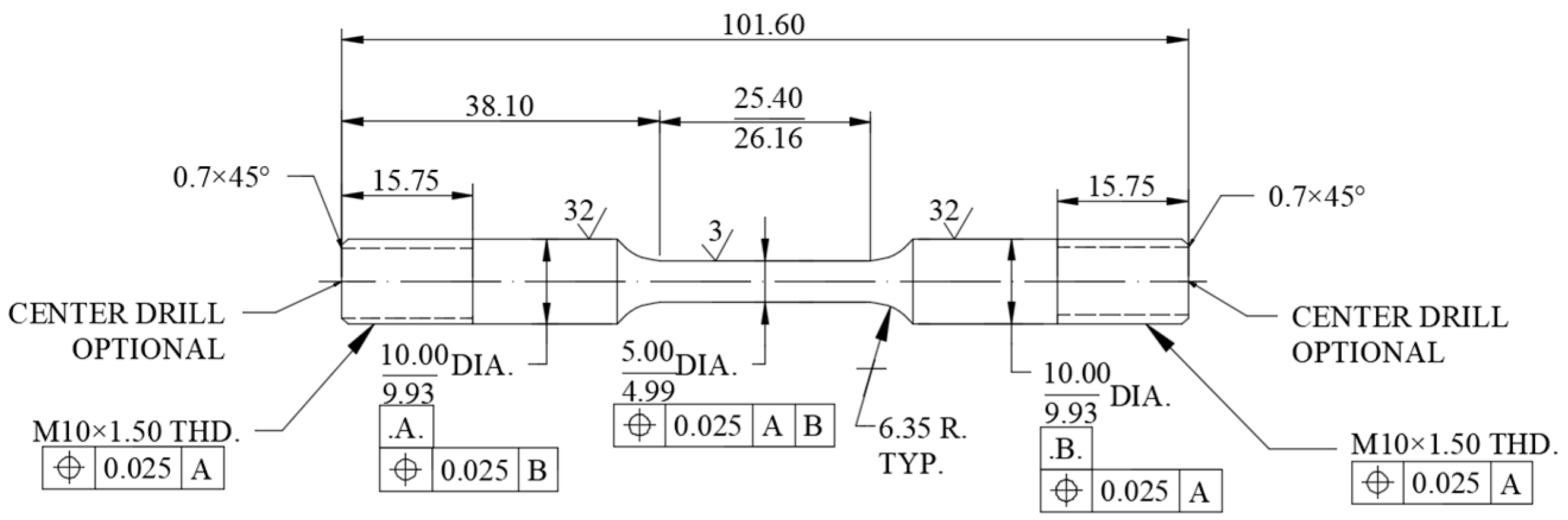
The test platform was built according to the stress corrosion characteristics. The test instruments and equipment mainly included a stress ring test system, a WDML-10 slow-rate tensile testing machine from Lichuang company in Xi’an, China, an industrial camera from JPLY Electronic Tech in Guangzhou, China, and a VMS-2010 manual image measuring instrument from Zhongte Precision Instrument Technology Co., Ltd in Dongguan, China. To be closer to the actual sucker rod, the test samples were bar samples, which were loaded axially to ensure that the simulated stress was closer to that of actual conditions. The sample was processed and provided by a sucker rod manufacturer, and its material composition and heat treatment processes are the same as the actual sucker rod used on site. The size of the sample was determined according to the provisions of the stress corrosion sample in the NACE TM 0177-2005 standard [43] of the National Association of Corrosion Engineers. The detailed dimensions of the sample are shown in Figure 1. The sucker rod samples used in the test were high-strength sucker rods mainly used in the oilfield: the H-grade ultra-high-strength 4330 and 30CrMoA sucker rods and the D-grade high-strength 20CrMoA and 4142 sucker rods.

Figure 1.
Detailed dimensions of the high-strength sucker rod test samples.
According to the standard GB/T 228.1-2010 [44] Metallic Materials Tensile Test, Part 1, the room-temperature test method, the non-corroded 4330, 30CrMoA, 20CrMoA, and 4142 sucker rod samples were broken by a tensile testing machine, and the tensile strength was calculated as σb. The tensile strengths of four high-strength sucker rod materials are shown in Table 1.

Table 1.
The tensile strength of four high-strength sucker rod materials.
2.2. Evaluation Method for Stress Corrosion Test of the Sucker Rods
In the test of the stress corrosion resistance of the high-strength sucker rods under high water cut conditions, the stress loading was set as 65% σb, 70% σb, 75% σb, 80% σb, and 85% σb (five different service strengths). Four kinds of high-strength sucker rod materials were used in the test. A constant stress was loaded in the corrosive environment and corroded simultaneously, and then the tensile test was carried out on the samples. Elongation loss (plastic loss) and absorbed work loss were used as the evaluation indexes of the stress corrosion sensitivity of the test samples to study the adaptability of these four kinds of rods to corrosion environments.
The absorbed work was obtained by calculating the area between the stress–strain curve and the coordinate axis of the tensile sample. The elongation loss and absorbed work loss are calculated according to the following equations:
where is the elongation of the material in the air; is the elongation of the material in the corrosive medium; is the absorbed work before the material breaks in the air; and is the absorbed energy before the material breaks in the corrosive medium.
2.3. Design of the Corrosive Medium Concentration
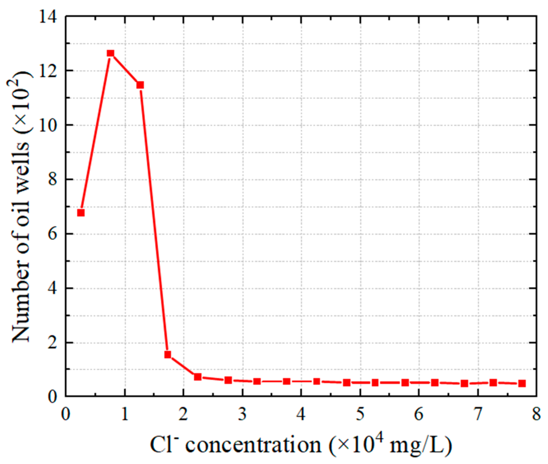
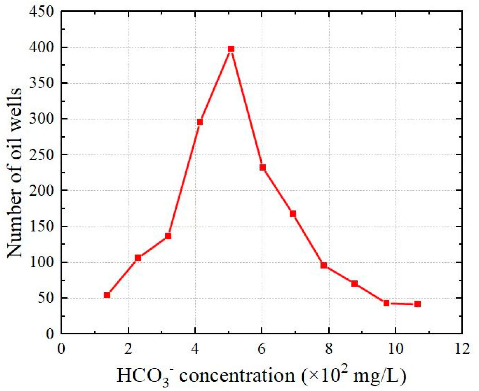
In the stress corrosion test, to make the composition of the corrosion solution similar to that of genuine well fluid, the corrosion solution medium was analyzed according to the water quality data of 3962 wells, as provided by the Shengli Oilfield Testing Center. The results show that [8]: the 3962 wells mainly contain Cl−, HCO3−, Ca2+, Mg2+, Na+, and K+, and a few wells also contain SO42− and CO32−. The oil wells with a Cl− concentration exceeding 20,000 mg/L only account for 2.46% of the total number of wells. The Cl− concentration of most oil wells is distributed in the range of 0–20,000 mg/L; the HCO3− concentration is mainly distributed in the range of 0–800 mg/L, and the proportion of oil wells exceeding 800 mg/L is only about 6.5%; the Ca2+ and Mg2+ concentrations are mainly concentrated in the range of 0–800 mg/L, and the number of oil wells with concentrations that are more significant than 800 mg/L is tiny. Because the influence periods of Ca2+ and Mg2+ are long and the influence factors are small, these two ions were not considered in the test. Sodium and potassium ions have high activity and hardly participate in rod corrosion behavior in well fluid, so their influence was not considered in the experiment. According to the above-mentioned water quality analysis and ion corrosion mechanism, it was determined that the medium of the stress corrosion test solution should consist of Cl−, HCO3−, and Na+. Based on the data from 3962 well fluids, the concentration distribution of the Cl− and HCO3− ions is shown in Figure 2 and Figure 3.
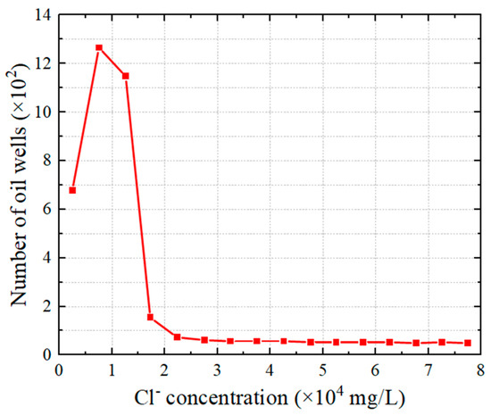
Figure 2.
Concentration distribution of chloride ions in sampled well fluids.
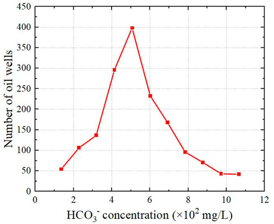
Figure 3.
Concentration distribution of bicarbonate ions in sampled well fluids.
In order to study the influence of Cl− and HCO3− on the stress corrosion of four kinds of high-strength sucker rods, i.e., grade H 4330 and 30CrMoA and grade D 20CrMoA and 4142, a single-factor stress corrosion test was designed; that is, only the concentration of Cl− or HCO3− was taken as a single variable. The test solution was prepared with NaCl and NaHCO3 as solutes. The concentration of Cl− in the solution was set to the 5 values of 5000 mg/L, 10,000 mg/L, 15,000 mg/L, 20,000 mg/L, and 25,000 mg/L, and the concentration of HCO3− was set to the 5 values of 200 mg/L, 400 mg/L, 600 mg/L, 800 mg/L, and 1000 mg/L. The stress corrosion test was carried out on 4 kinds of high-strength sucker rods, i.e., the grade H 4330 and 30CrMoA sucker rods and the grade D 20CrMoA and 4142 sucker rods, respectively, and the stress loading was set as 70% σb. The specific design scheme is shown in Table 2.
Table 2.
Design scheme for the ion concentrations in different corrosion solutions.
3. Analysis of Experimental Results
3.1. Corrosion Analysis
The corrosion of the grade H ultra-high-strength 4330 and 30CrMoA sucker rods and the grade D 4142 and 20CrMoA high-strength sucker rods was observed and recorded with an industrial camera after 10 days and 30 days, respectively.
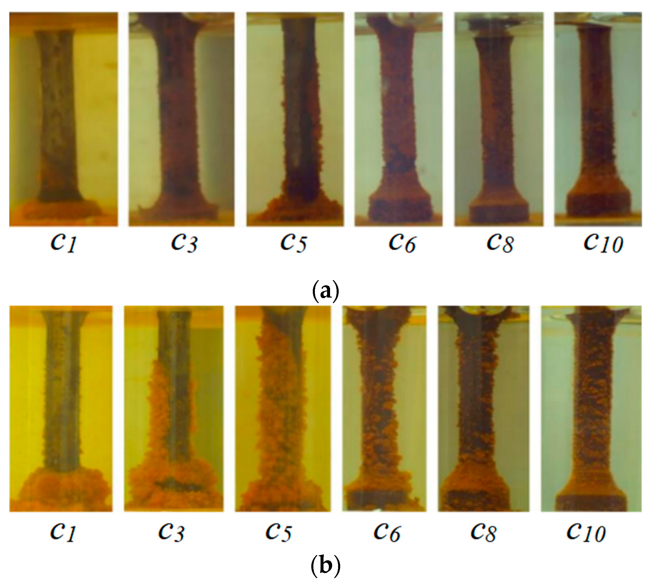
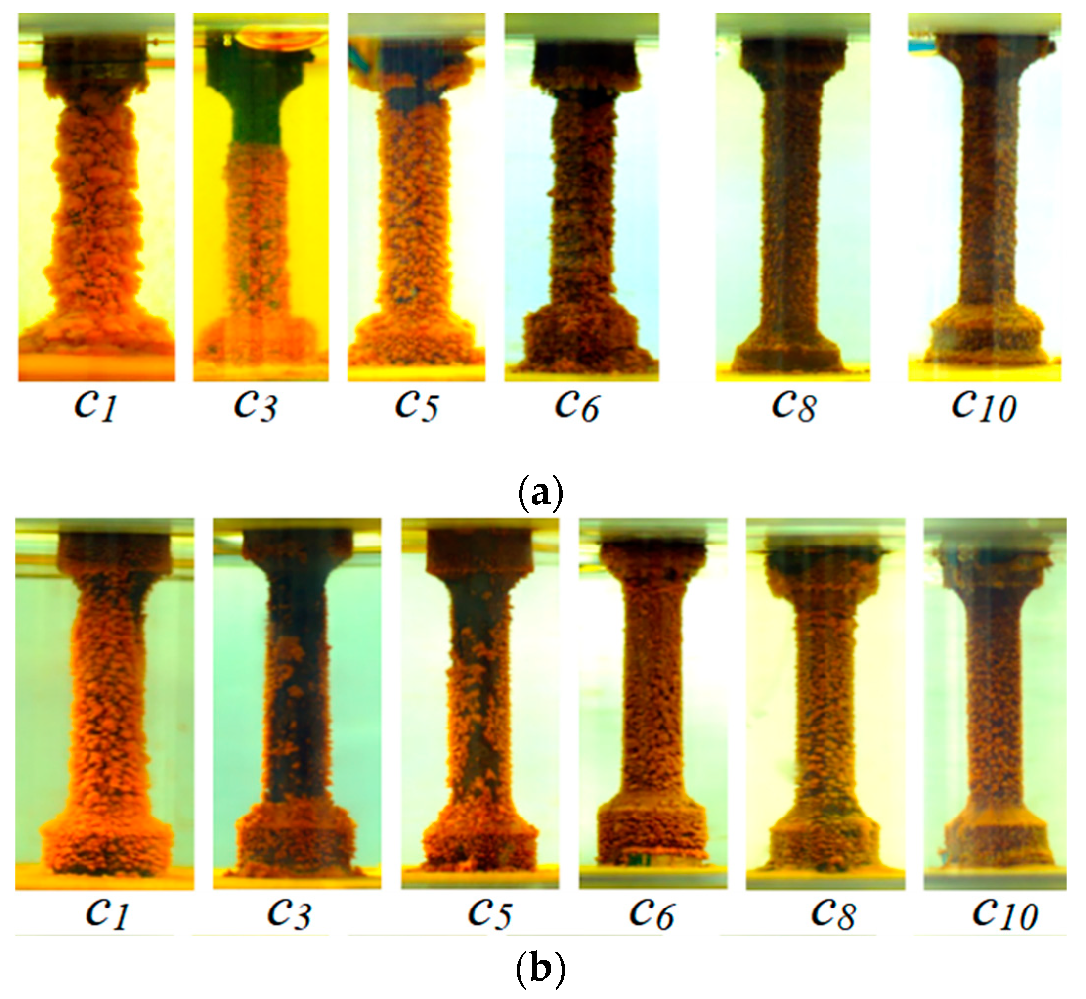
It can be seen from samples 1–5, shown in Figure 4 and Figure 5, that the initial corrosion rates of the 4330 and 30CrMoA materials in the Cl− environment are slightly related to the Cl− concentration, and the corrosion is slow, but light-yellow powdery corrosives appear at first, and the sample surface is smooth. With the increase in time, under the action of the stress and corrosion medium, the oxidation film on the surface of the sample is corroded and damaged. The damaged surface and the undamaged surface form the anode and cathode, respectively. The metal at the anode converts into ions and is dissolved, and the generated current flows to the cathode. Since the anode area is much smaller than that of the cathode, the current density of the anode is large, further corroding the damaged surface. With the action of the tensile stress, cracks are gradually formed at the damaged part, and Cl− penetrates into the cracks, which further damages the oxidation film and prevent the formation of the oxidation film. The corrosion rate of the sample thus increases. After 30 days of stress corrosion, the color of the sample surface becomes darker, the metallic luster is lost, and the local corrosion is serious, as shown in Figure 6.
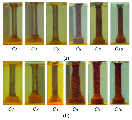
Figure 4.
Photos of the 4330 and 30CrMoA samples after 10 days of stress corrosion: (a) 4330; (b) 30CrMoA. (The labels in the figure designate solutions with different media concentrations: c1: ρ(Cl−) = 5000 mg/L, ρ(HCO3−) = 0 mg/L; c3: ρ(Cl−) = 15,000 mg/L, ρ(HCO3−) = 0 mg/L; c5: ρ(Cl−) = 25,000 mg/L, ρ(HCO3−) = 0 mg/L; c6: ρ(Cl−) = 15,000 mg/L, ρ(HCO3−) = 200 mg/L; c8: ρ(Cl−) = 15,000 mg/L, ρ(HCO3−) = 600 mg/L; c10: ρ(Cl−) = 15,000 mg/L, ρ(HCO3−) = 1000 mg/L).

Figure 5.
Photos of the 4330 and 30CrMoA samples after 30 days of stress corrosion: (a) 4330; (b) 30CrMoA. (The labels in the figure designate solutions with different media concentrations: c1: ρ(Cl−) = 5000 mg/L, ρ(HCO3−) = 0 mg/L; c3: ρ(Cl−) = 15,000 mg/L, ρ(HCO3−) = 0 mg/L; c5: ρ(Cl−) = 25,000 mg/L, ρ(HCO3−) = 0 mg/L; c6: ρ(Cl−) = 15,000 mg/L, ρ(HCO3−) = 200 mg/L; c8: ρ(Cl−) = 15,000 mg/L, ρ(HCO3−) = 600 mg/L; c10: ρ(Cl−) = 15,000 mg/L, ρ(HCO3−) = 1000 mg/L).
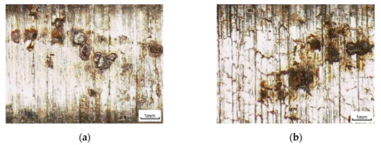
Figure 6.
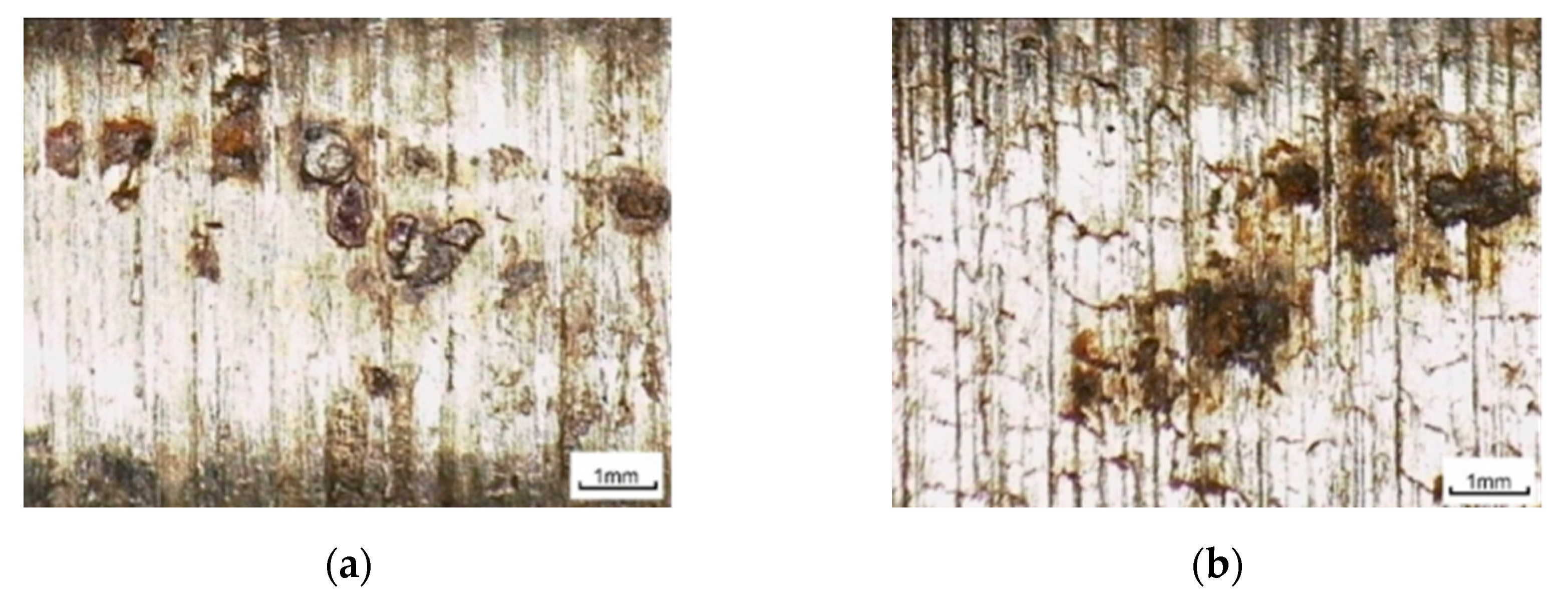
Optical micrograph of locally corroded surface: (a) 4330; (b) 30CrMoA (magnification: 200×).
When Cl− penetrates the surface of the specimen, the higher the Cl− concentration, the faster the local corrosion rate, and the corrosion becomes more serious. It can be seen from samples 6–10, as shown in Figure 4 and Figure 5, that the initial corrosion rate of the samples is faster, and the degree of corrosion is obvious in the alkaline environment containing HCO3− ions. The yellowish-brown granular corrosion product is FeCO3−. With time, the corrosion degree of the sample did not change significantly, and the corrosion rate was slow. After 10 days of stress corrosion, the corrosion rate of the sample remained slow, and the surface corrosion was uniform with fewer products, as shown in Figure 7. According to the comparison of groups (a) and (b) in Figure 4 and Figure 5, it can be seen intuitively that, under the same corrosion conditions, whether the Cl− corrosion medium is alone or the Cl− and HCO3− are acting together, the number of corrosion products on the surface of the 30CrMoA material, as visible to the naked eye, is greater than that on 4330, and the corrosion rate was also faster. Based on the surface corrosion of the sample, the stress corrosion resistance of the 30CrMoA sample is weaker than that of the 4330 sample.
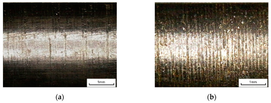
Figure 7.
Optical micrograph of uniformly corroded surface: (a) 4330; (b) 30CrMoA (magnification: 200×).
Figure 8 and Figure 9 show the corrosion of two D-strength pumping rod specimens, 20CrMoA and 4142, at a service strength of 70% σb after 10 and 30 days of stress corrosion tests, respectively.
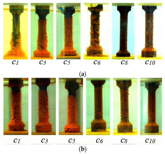
Figure 8.
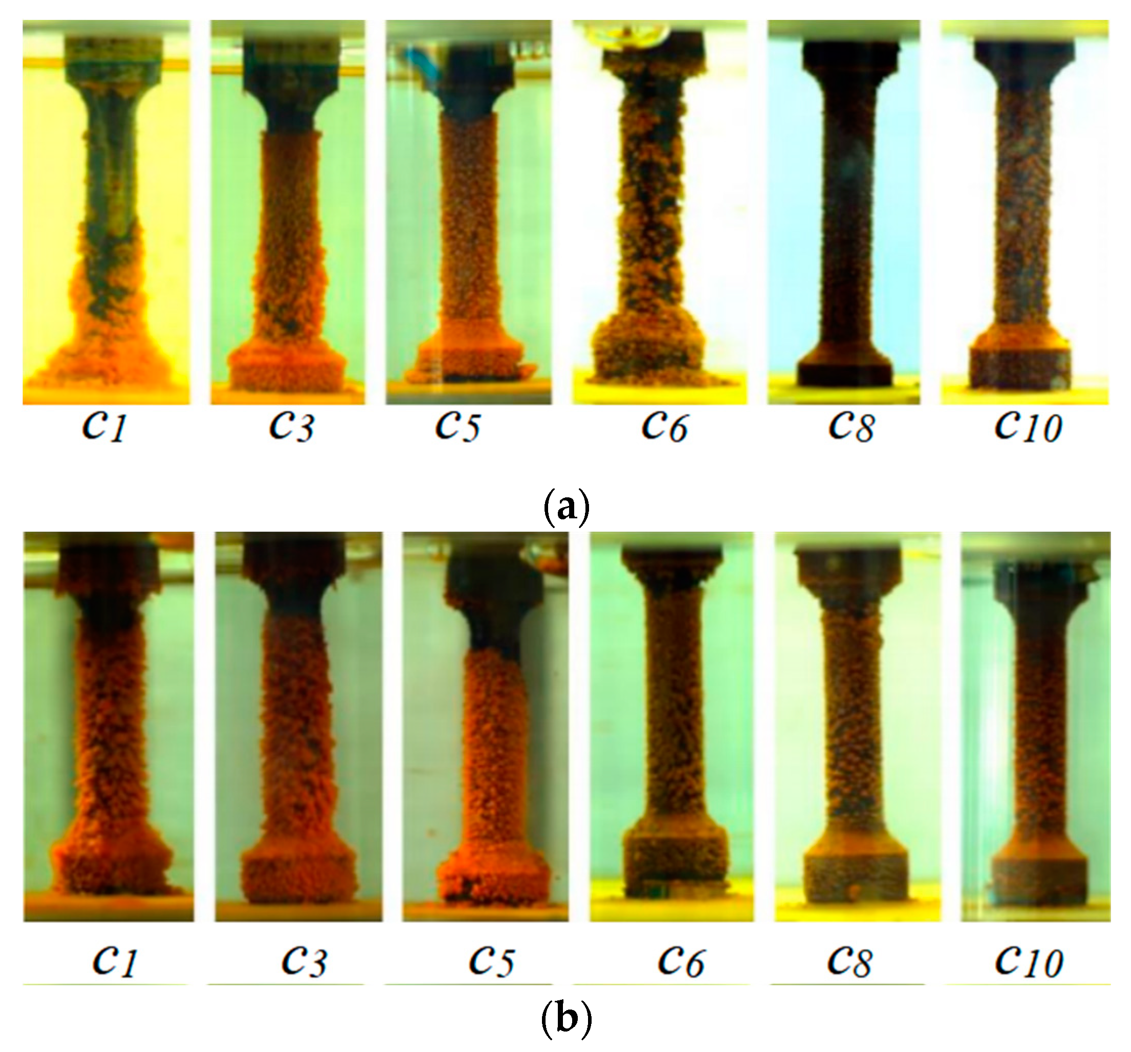
Photos of 4142 and 20CrMoA after 10 days of stress corrosion: (a) 4142; (b) 20CrMoA. (The labels in the figure designate solutions with different media concentrations: c1: ρ(Cl−) = 5000 mg/L, ρ(HCO3−) = 0 mg/L; c3: ρ(Cl−) = 15,000 mg/L, ρ(HCO3−) = 0 mg/L; c5: ρ(Cl−) = 25,000 mg/L, ρ(HCO3−) = 0 mg/L; c6: ρ(Cl−) = 15,000 mg/L, ρ(HCO3−) = 200 mg/L; c8: ρ(Cl−) = 15,000 mg/L, ρ(HCO3−) = 600 mg/L; c10: ρ(Cl−) = 15,000 mg/L, ρ(HCO3−) = 1000 mg/L).
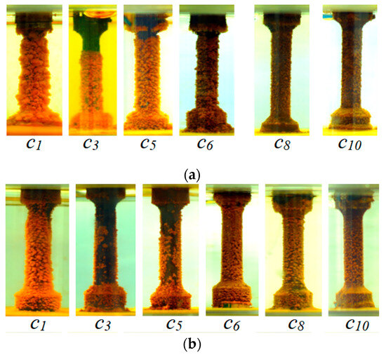
Figure 9.
Photos of 4142 and 20CrMoA after 30 days of stress corrosion: (a) 4142; (b) 20CrMoA. (The labels in the figure designate solutions with different media concentrations: c1: ρ(Cl−) = 5000 mg/L, ρ(HCO3−) = 0 mg/L; c3: ρ(Cl−) = 15,000 mg/L, ρ(HCO3−) = 0 mg/L; c5: ρ(Cl−) = 25,000 mg/L, ρ(HCO3−) = 0 mg/L; c6: ρ(Cl−) = 15,000 mg/L, ρ(HCO3−) = 200 mg/L; c8: ρ(Cl−) = 15,000 mg/L, ρ(HCO3−) = 600 mg/L; c10: ρ(Cl−) = 15,000 mg/L, ρ(HCO3−) = 1000 mg/L).
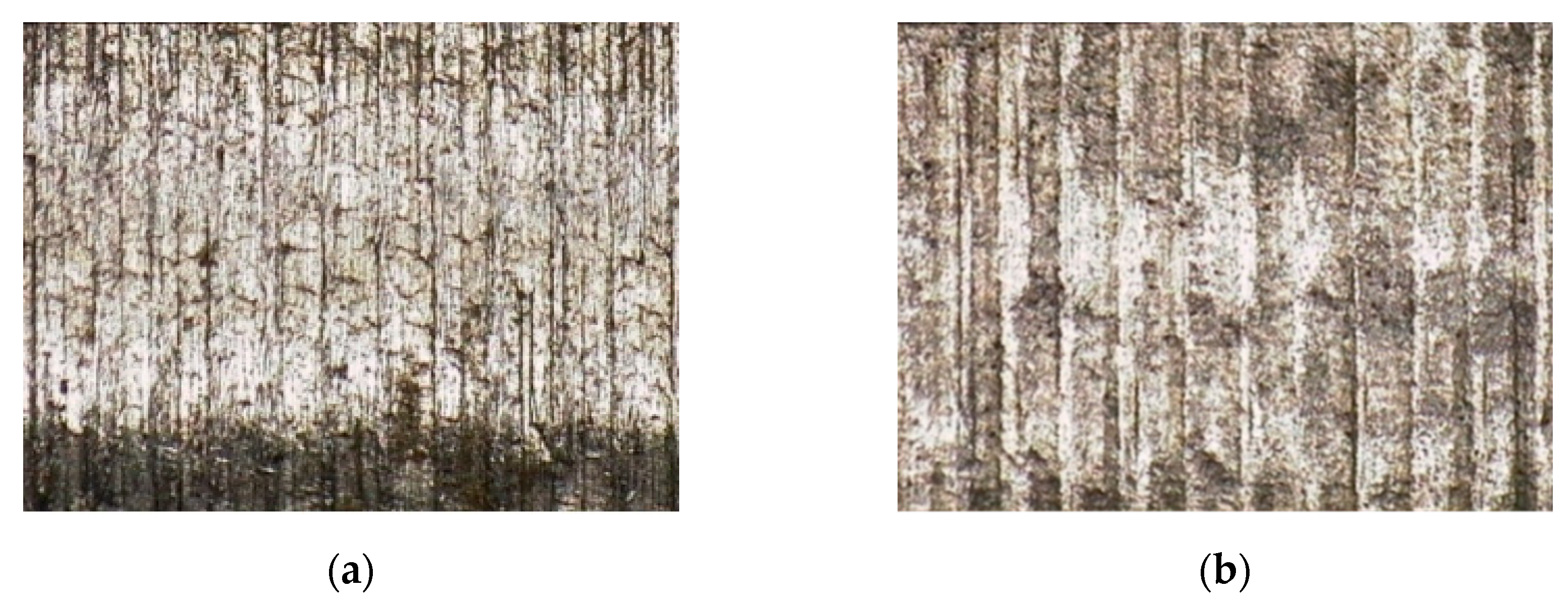
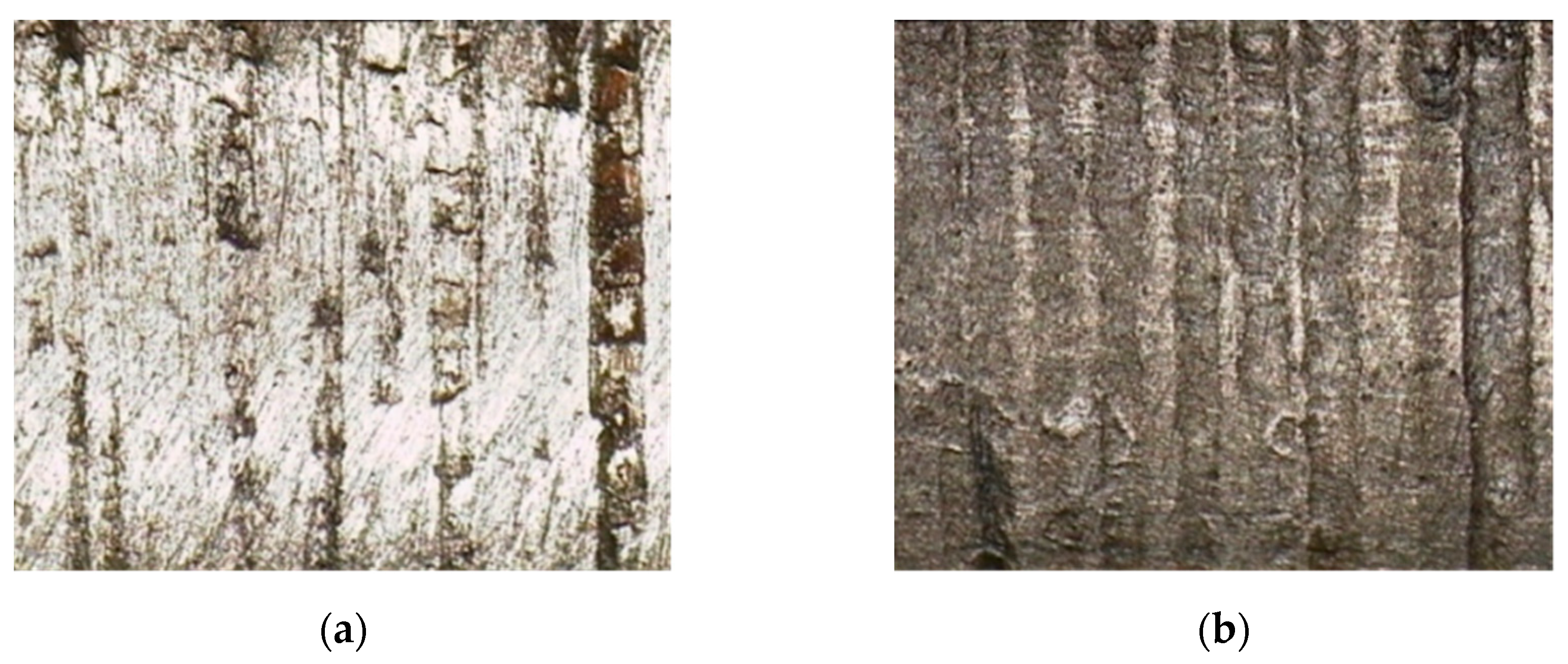
According to the comparison between groups (a) and (b) in Figure 8 and Figure 9, it can be seen that the corrosion conditions of the grade D high-strength 4142 and 20CrMoA sucker rods in the Cl−-containing solution are similar to those of the 4330 and 30CrMoA sucker rods. However, the corrosion rate is higher. After 10 days of corrosion, the corrosion products on their surfaces are much greater than those of the 4330 and 30CrMoA specimens. With the increase in bicarbonate concentration, the fewer the corrosion products and the more obvious the inhibition of Cl− corrosion. The products on the surface of samples 6–10 are significantly fewer than those of sample 3 in the 1500 mg/L Cl− solution. Comparing the 20CrMoA specimen with the 4142 specimen, the stress corrosion resistance of the 20CrMoA specimen is better in the solution containing only Cl−, but that is not obvious. On the contrary, the corrosion inhibition of the 4142 specimen in the Cl− solution by HCO3− is more obvious. After the specimen was disassembled and cleaned after 30 days of corrosion, as shown in Figure 10 and Figure 11, the surfaces of both the 20CrMoA and 4142 specimens were found to have no obvious pitting under 180× magnification, and the main traces were the processing traces on the surfaces of the specimens, indicating that the surfaces were, in general, uniformly corroded.
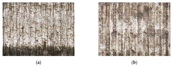
Figure 10.
Surface optical micrograph of 20CrMoA specimen before and after corrosion (magnification: 180×): (a) surface before corrosion; (b) surface after corrosion.
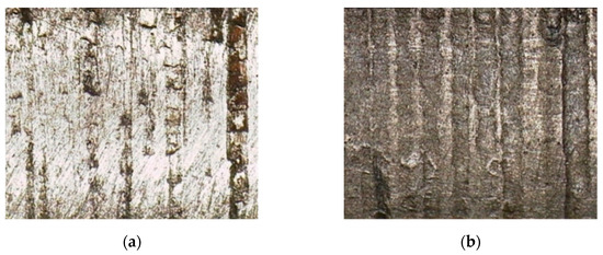
Figure 11.
Surface optical micrograph of 4142 specimen before and after corrosion (magnification: 180×): (a) surface before corrosion; (b) surface after corrosion.
3.2. Tensile Test Results
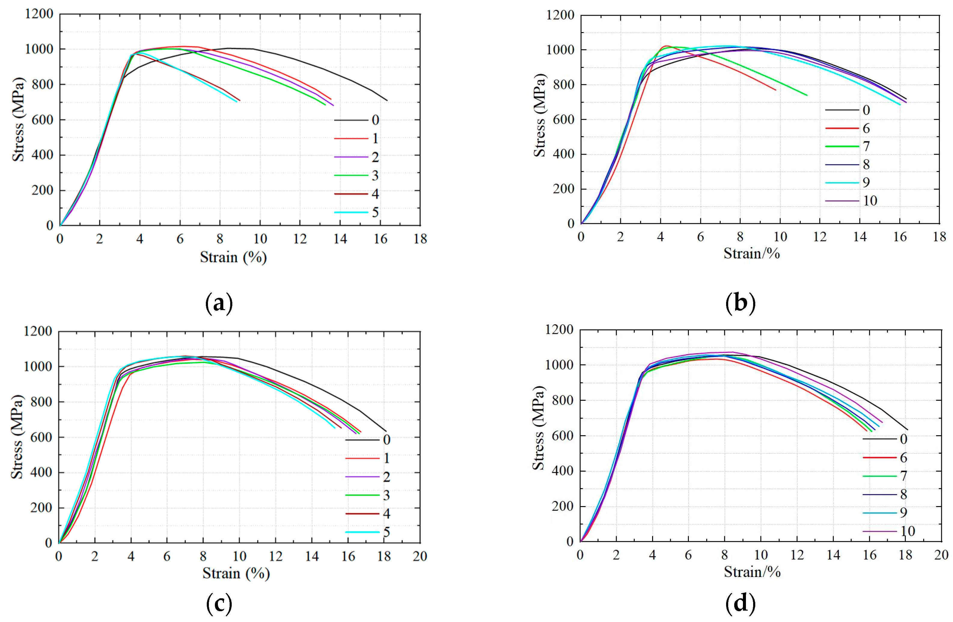
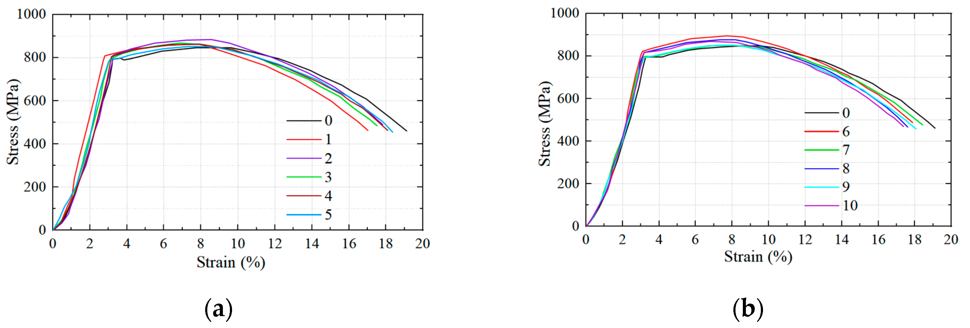
After 30 days of stress corrosion, we removed the sample from the stress ring and cleaned it, and then we removed it from the WDML-10 slow-rate tensile testing machine to obtain the stress–strain curve, as shown in Figure 12.
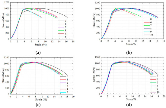
Figure 12.
Stress–strain curves of the 4330 and 30CrMoA sucker rod samples after stress corrosion: (a) Nos. 1–5: 4330 strain curve; (b) Nos. 6–10: 4330 strain curve; (c) Nos. 1–5: 30CrMoA strain curve; (d) Nos. 6–10: 30CrMoA strain curve.
Curve No. 0 in Figure 12 is the stress–strain curve of the sample without stress corrosion in air at a normal temperature. It can be seen from Figure 12a that, after the stress corrosion of the 4330 sample by the Cl− corrosive medium, its elastic deformation zone increases, the plastic deformation zone decreases, the fracture time of the material is significantly shortened, and the plastic loss of the material is obvious. Figure 12b shows that, for the 4330 sample, when Cl− and HCO3− coexist, the concentration of Cl− is fixed. With an increase in HCO3− concentration, the plastic deformation zone of the material increases. When the HCO3− concentration is lower than 600 mg/L, the plastic deformation zone of the material is smaller because, when the HCO3− concentration is lower, the inhibition effect on Cl− corrosion is smaller. When the HCO3− concentration increases to 800 mg/L or greater, the plastic deformation zone of the material is similar to that of the stress-free corrosion specimen, and the inhibitory effect of HCO3− on Cl− corrosion is obvious.
In Figure 12c,d, the elastic deformation zone of the 30CrMoA sample is unchanged, both under the Cl− stress corrosion environment and under the combined action of HCO3− and Cl−, and only the plastic deformation zone is changed; along with the increase in ρ(Cl−), the plastic deformation zone of the 30CrMoA sample becomes smaller and the plastic loss increases.
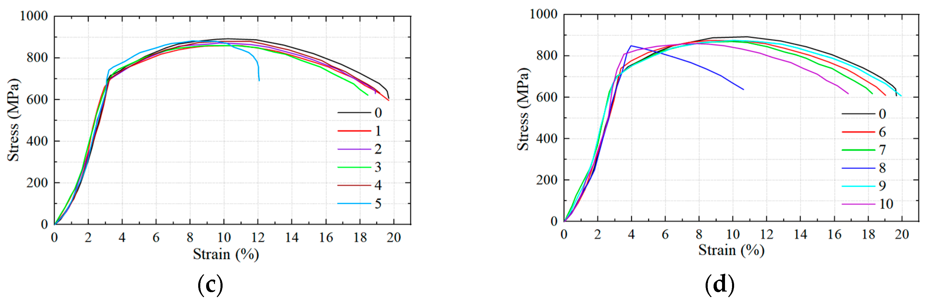
The tensile curves of the 20CrMoA and 4142 samples are shown in Figure 13.
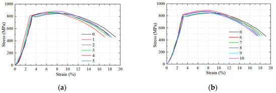
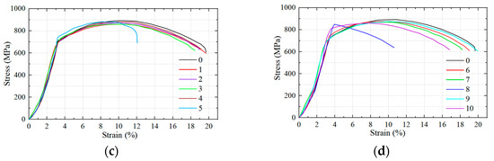
Figure 13.
Stress–strain curves of the 20CrMoA and 4142 sucker rod samples after stress corrosion: (a) Nos. 1–5: 20CrMoA strain curve; (b) Nos. 6–10: 20CrMoA strain curve; (c) Nos. 1–5: 4142 strain curve; (d) Nos. 6–10: 4142 strain curve.
A comparison of Figure 12 and Figure 13 shows that the tensile strengths of the 20CrMoA and 4142 samples were significantly lower than those of the 4330 and 30CrMoA samples, which belonged to grade D high-strength pumping rods. The tensile curves of these two materials after corrosion in different environments were also relatively consistent, and the elastic zone did not change significantly after stress corrosion. However, Figure 13d shows that HCO3− has a greater effect on the stress corrosion of the 4142 sample.
3.3. Stress Corrosion Sensitivity Analysis
Obtained via the collection and processing of the test data, the elongation loss and absorbed work loss statistics of the four materials, 4330, 30CrMoA, 4142, and 20CrMoA, after using a 70% σb strength stress corrosion test are shown in Table 3 below.
Table 3.
Elongation and absorbed work loss statistics of four materials after stress corrosion.
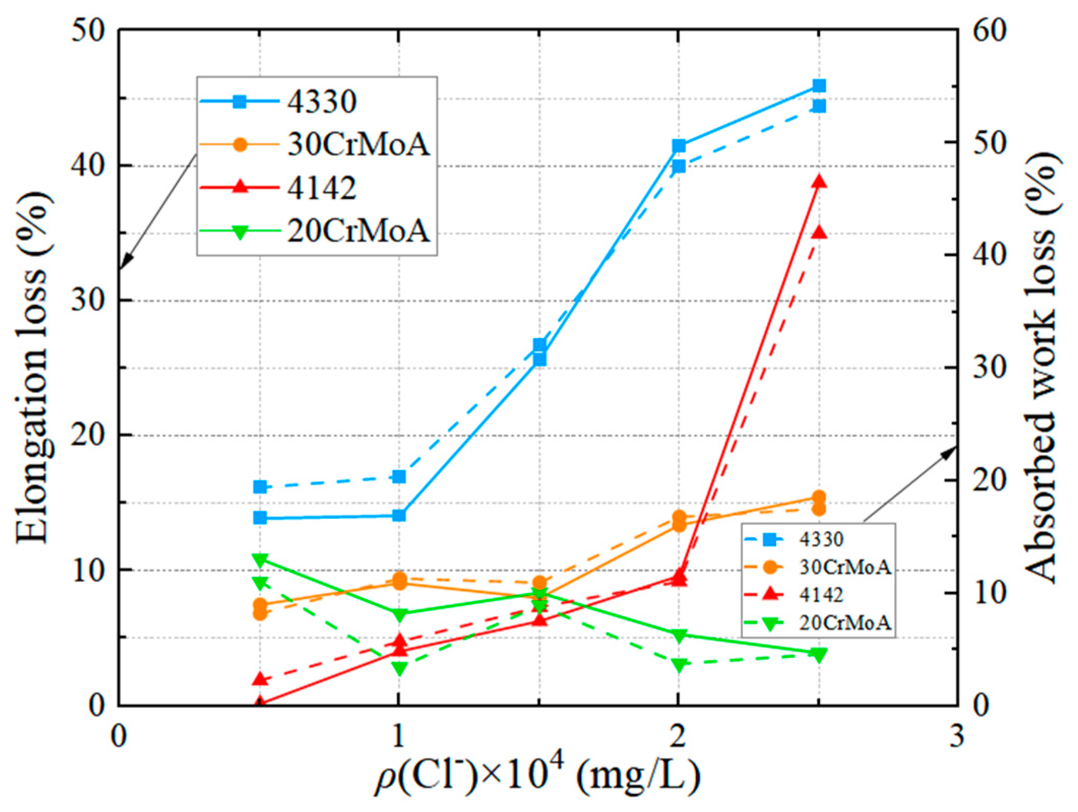
The test results for the four materials of stress corrosion sensitivity measured through elongation and fracture absorption work are shown in Figure 14 and Figure 15. In the corrosive well fluid containing Cl−, the plasticity loss of the 4330, 30CrMoA, and 4142 materials enlarged continuously with the increase in ρ(Cl−), which indicates that the higher the concentration of Cl−, the more sensitive the stress corrosion of high-strength pumping rods. However, the plastic loss in the 20CrMoA material pumping rod demonstrates a decreasing trend, and the 20CrMoA material shows a more stable level of stress corrosion in a medium with a high Cl− concentration. Therefore, the stress corrosion resistance of the 4330 and 30CrMoA ultra-high-strength rods in a medium with a high Cl− concentration is not necessarily greater than that of the D-grade rods, and the sensitivity of the H-grade pumping rods to Cl− stress corrosion is more obvious than that of the D-grade rods. Considering the high mineralization and high water content of well fluids entering mid-to-late-stage extraction wells, Cl− is the most important corrosive medium, and the stress corrosion resistance of different materials to specific well fluids must be considered when selecting high-strength rods.

Figure 14.
Stress corrosion sensitivity of four materials at different (Cl−)s.
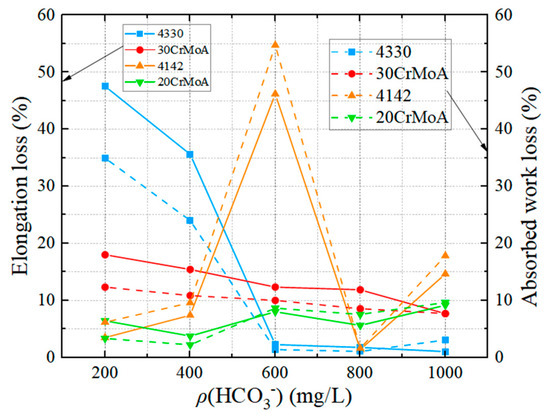
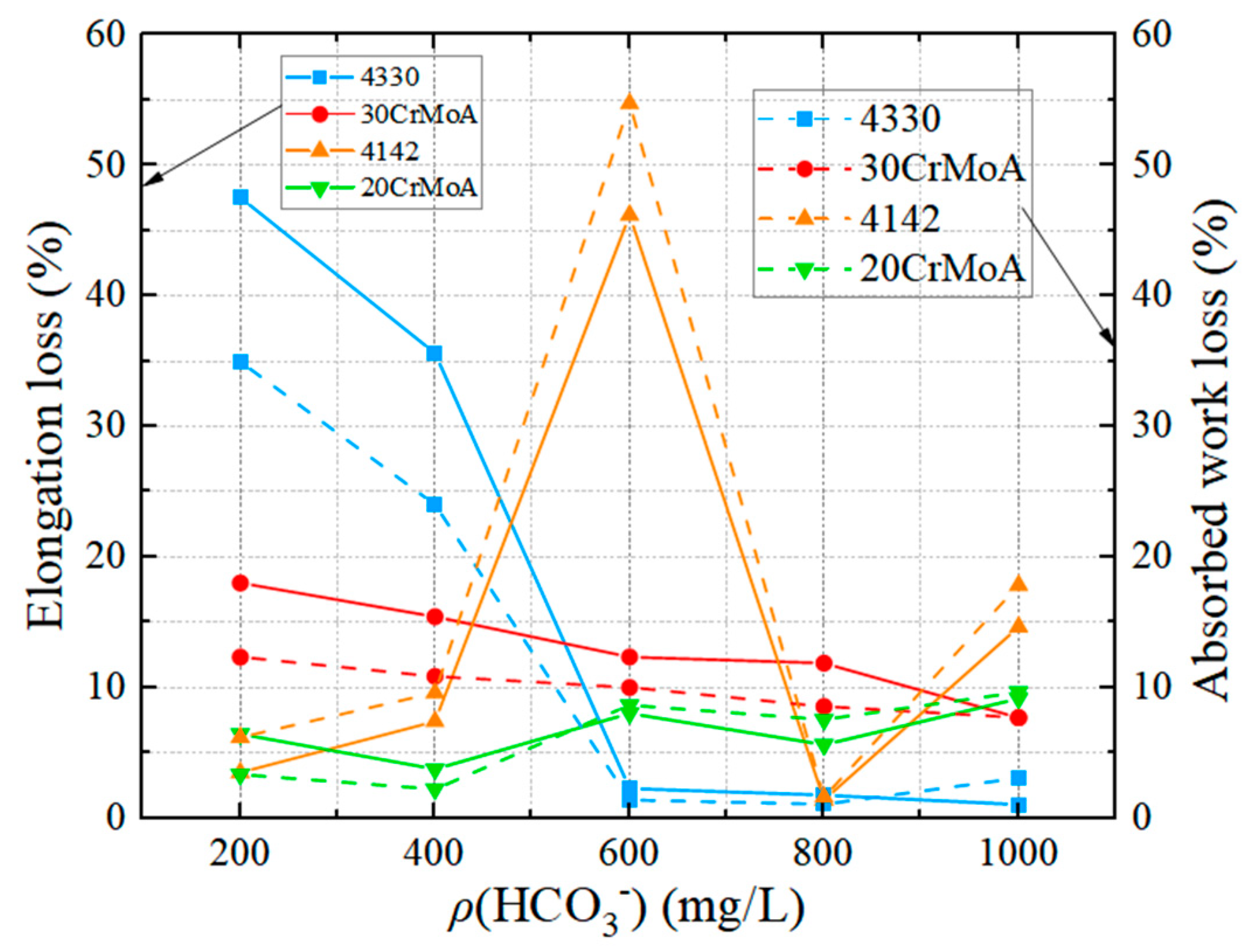
Figure 15.
Stress corrosion sensitivity of four materials at different (HCO3−)s.
The relationships between the elongation loss and the concentration of HCO3− for the four materials are shown in Figure 15. The higher the concentration of HCO3−, the smaller the elongation loss for the 4330 and 4142 pumping rods, and the inhibition of the stress corrosion of the 4330 and 4142 rods by HCO3− is obvious. Meanwhile, under the same test conditions, the analysis of the elongation loss test results showed that the 30CrMoA and 20CrMoA rods were more stable than the 4330 and 4142 rods of the same strength level.
Based on the above analysis of the corrosion of sucker rods, obtained through the photo comparison of the corrosion process and the weighing of the sucker rod samples after 30 days of corrosion, we found that the corrosion products on the surface of the 30CrMoA sample piece were greater in number than those on the 4330 sample piece, and the corrosion products on the surface of the 20CrMoA sample piece were greater in number than those on the 4142 sample piece with the same amount of corrosion time. If the corrosion resistance of the sucker rod is described according to the weight loss method in the static coupon corrosion test, it can be concluded that the 30CrMoA sample is more susceptible to corrosion than the 4330 sample, and the 20CrMoA sample is more susceptible to corrosion than the 4142 sample. However, through the stress corrosion sensitivity analysis, we found that the results of elongation loss and absorption work loss of the two materials were opposite to the surface phenomenon of the corrosion process under different Cl− concentrations. Usually, the degree of corrosion is measured by the number of corrosion products or the weight loss of a sample piece in the corrosion solution, but for the components bearing a large working load, the measurement index of a static corrosion test under no-load conditions is not necessarily able to accurately measure the stress corrosion characteristics. It can be concluded that the test results described by the corrosion rate and plastic loss based on the weight loss may be contradictory to the determination of the corrosion sensitivity of the material under working conditions.
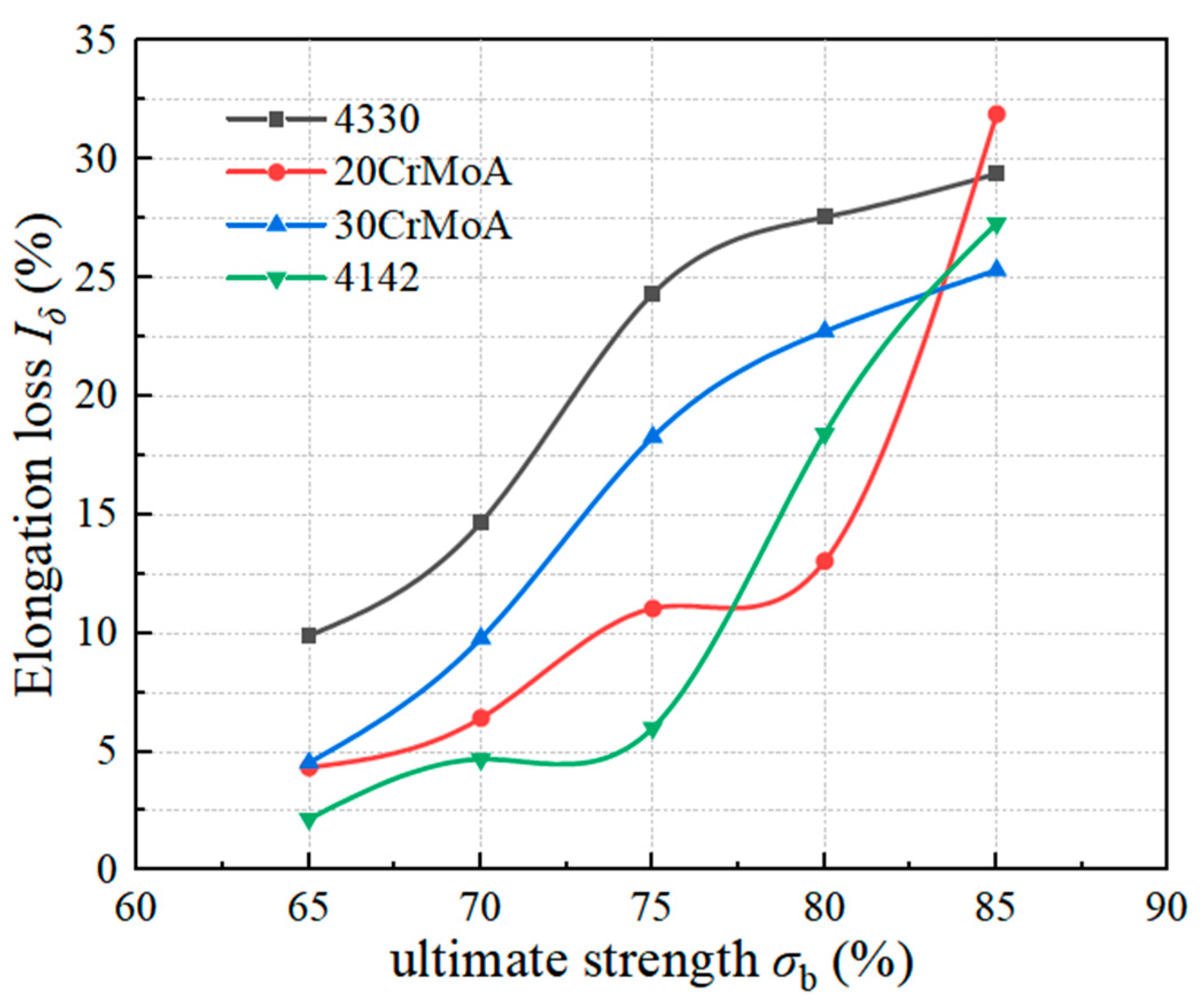
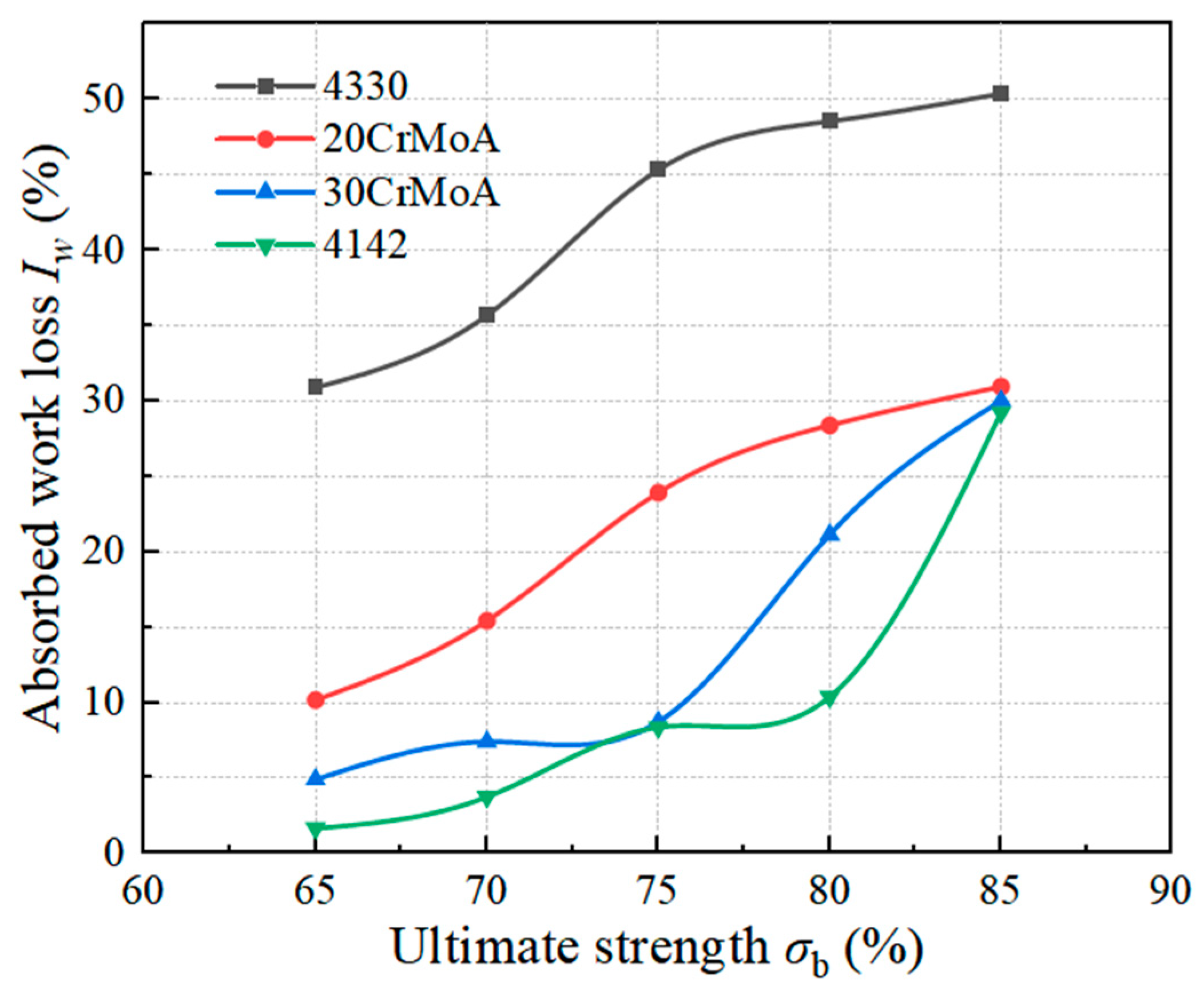
A stress corrosion test of four kinds of high-strength sucker rods under different use strengths was further designed. The changes in the elongation loss of the four materials under different use strengths, when the concentration of Cl− was 10,000 mg/L and the concentration of HCO3− was 0, are shown in Figure 16, and the changes in the absorbed work loss of the four materials under different use strengths, when the concentration of Cl− was 15,000 mg/L and the concentration of HCO3− was 400 mg/L, are shown in Figure 17. It can be seen from Figure 16 and Figure 17 that the elongation loss and absorbed work loss of the four kinds of high-strength pumping rods increased gradually with the increase in use strength, which indicates that the higher the use strength, the more sensitive the stress corrosion is, and an increase in stress can promote corrosion. It can be seen from Figure 16 that the changing trend of the H-grade 4330 and 30CrMoA sucker rods is consistent, and the increasing trend of elongation loss slows down when the use intensity is greater than 75% σb; the changing trend of the D-grade 20CrMoA and 4142 sucker rods is consistent, and the increasing trend of elongation loss steepens when the use intensity is greater than 75% σb, which suggests that the higher the use intensity, the more sensitive the stress corrosion of the D-grade pumping rods is.
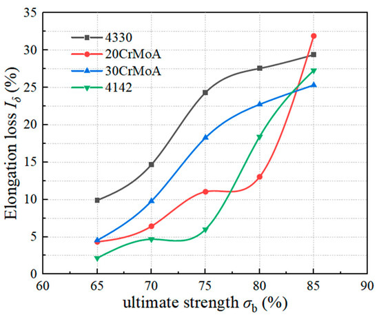
Figure 16.
Elongation loss of four materials at different use intensities.

Figure 17.
Absorption work loss of four materials at different use intensities.
4. Conclusions
- (1)
- The stress corrosion resistance of a sucker rod is not necessarily related to the tensile strength of the sucker rod. The elongation loss and absorbed work loss of the grade H ultra-high-strength 4330 sucker rod after stress corrosion in the Cl− and HCO3− solution are greater than those of the grade D high-strength 4142 and 20CrMoA sucker rods, so the stress corrosion resistance of the grade H ultra-high-strength sucker rod is not necessarily superior to that of the grade D high-strength sucker rod.
- (2)
- The class H ultra-high-strength 4330 sucker rod is not suitable for high-Cl−-concentration well conditions, but it is suitable for operation under alkaline conditions with the coexistence of corrosive media such as HCO3− and Cl−. Under the condition of high salinity with strong corrosivity, the stress corrosion cracking susceptibility of the 30CrMoA rod is lower, so it is more stable. For the grade D high-strength sucker rods, the 20CrMoA rod is less susceptible to stress corrosion than the 4142 rod, and the 20CrMoA rod is more stable.
- (3)
- In high-salinity well fluid, with an increase in use strength, the stress corrosion cracking susceptibility of high-strength sucker rods increases. Among them, the grade D high-strength 4142 and 20CrMoA sucker rods are more affected by stress corrosion when the service strength is greater than 75% σb.
- (4)
- The test results described by the weight-loss-based corrosion rate and plastic loss may be contradictory to the determination of the corrosion susceptibility of the material under working conditions.
Author Contributions
Conceptualization, F.Z. and J.L.; methodology, F.Z. and J.L.; software, J.L.; validation, H.Z. and C.J.; formal analysis, F.Z. and J.L.; investigation, F.Z. and J.L.; resources, F.Z. and J.L.; data curation, H.Z. and B.W.; writing—original draft preparation, J.L.; writing—review and editing, F.Z. and J.L.; visualization, J.L.; supervision, B.W. and C.J.; project administration, F.Z. and Y.Q.; funding acquisition, F.Z. and Y.Q. All authors have read and agreed to the published version of the manuscript.
Funding
This research was funded by the National Science and Technology Major Project of China (Grant Nos. 2016ZX05066004-002 and 2017ZX05064004-007) and the Shandong Provincial Natural Science Foundation of China (Grant No. ZR2020MD038).
Data Availability Statement
The data that support the findings in this study are available from the author, J.L., upon reasonable request.
Acknowledgments
Sincere thanks to Yongjie He for his guidance on the experimental research and manuscript preparation and for his contributions.
Conflicts of Interest
The authors declare no conflict of interest.
References
- Zhang, J.J. Analysis and Research on the Factors Influencing the Breaking of Sucker Rods in Ultra-Deep Wells in Tahe Oilfield. Master’s Thesis, Southwest Petroleum University, Chengdu, China, 2016. [Google Scholar]
- Wang, S.L.; Zheng, Z.Y. Domestic and Foreign Application of the Super-Strength Sucker Rod. Oil Field Equip. 2008, 4, 24–27. [Google Scholar]
- Wang, Y.H. Application of HY grade ultra high strength sucker rod in Wennan Oilfield. Energy Conserv. Pet. Petrochem. Ind. 2019, 9, 63–65. [Google Scholar]
- Liang, H.; Li, X.M. Analysis on failure mechanism of sucker rod pumping system. Mater. Res. Appl. 2014, 1219, 1–3. [Google Scholar] [CrossRef]
- Wang, L.; Tian, Y.; Yu, X.Y.; Wang, C.; Yao, B.W.; Wang, S.H.; Philip, H.W.; Wang, X.; Yang, Z.Z.; Wang, Y.H.; et al. Advances in improved/enhanced oil recovery technologies for tight and shale reservoirs. Fuel 2017, 210, 425–435. [Google Scholar] [CrossRef]
- Fan, S.; Liang, Y.; Wang, L.Y.; Lei, Y.; Shi, H.X. Allowable Stress Calculation and Fatigue Life Prediction for H-Class Sucker Rods. Pet. Drill. Tech. 2017, 45, 88–92. [Google Scholar]
- He, Y.J. Corrosion Fatigue Behavior of High Strength Sucker Rod in High Water Conditions. Master’s Thesis, China University of Petroleum (East China), Qingdao, China, 2017. [Google Scholar]
- Li, Y. The Research with Corrosion Resistance to Stress of Sucker Rod in High Water Conditions. Master’s Thesis, China University of Petroleum (East China), Qingdao, China, 2014. [Google Scholar]
- Wang, Z.Q.; Huang, X.G.; Guo, Y.S.; Pei, Z.H. Corrosion Behavior of Super High Strength Steel FG20 in High-Sulfur Oilfield Water with Different pH Values. Mater. Mech. Eng. 2020, 44, 42–46. [Google Scholar]
- Yao, X.F.; Tian, W.; Xie, F.Q. Corrosion Behavior of Super 13Cr Tubing Steel in Cl− Solution and Electrochemical Characteristics of Corrosion Film on Its Surface. Mater. Mech. Eng. 2019, 43, 12–16. [Google Scholar]
- SY/T 5029-2006; Sucker Rods. Industry Standard-Petroleum. Yumen Oilfield Branch Machinery Factory: Jiuquan, China, 2007.
- Dong, Z.D.; Tong, Z.; Zhou, H.Y.; Wang, H.M.; Zheng, W.Y.; Sun, X.R.; Ding, H. Service Failure of Sucker Rods and Development of Sucker Rod Steels: A Review. Mater. Rev. 2021, 35, 19161–19169. [Google Scholar]
- Li, D.J.; Wang, W.; Pang, B.; Lin, W.; Li, W.Z.; Ji, L.; Feng, Y.R. Influence factors on corrosion fatigue life of sucker rods used in coalbed methane well. Trans. Mater. Heat Treat. 2017, 38, 121–127. [Google Scholar]
- Yang, H.; Zhong, W.H.; Liu, Q.; Ma, T.W.; Shang, Z.X. Cause analysis and integrated prevention for breakage & drop out of the sucker rod string. Petrochem. Ind. Technol. 2015, 22, 155. [Google Scholar]
- Li, D.G.; Fen, Y.R.; Bai, Z.Q.; Zhu, J.W.; Zheng, M.S. Influence of temperature, chloride ions, and chromium element on the electronic property of passive film formed on carbon steel in bicarbonate/carbonate buffer solution. Electrochim. Acta 2007, 52, 7877–7884. [Google Scholar] [CrossRef]
- Han, Z.Y.; Huang, X.G. Investigations on corrosion behaviors of super-strength sucker rod FG20 steel in high SO42− environment. J. Mater. Res. Technol. 2019, 8, 788–794. [Google Scholar]
- Hao, L.L. Analysis of the Failure of Sucker Rods and Research on Its Residual Life. Master’s Thesis, Daqing Petroleum Institute, Daqing, China, 2008. [Google Scholar]
- Lin, H.; Xu, J.; Fan, B.T.; Zhang, Y.C.; Wang, G.P.; Huo, H.B.; Yin, Q.S. Mechanical Properties of L80 Steel in CO2/H2S Environment. Surf. Technol. 2016, 45, 91–96. [Google Scholar]
- Tian, G.; Yi, Y.G.; Han, X.; Cai, L.L.; Yu, H.Y.; Zeng, D.Z. Corrosion Law and Corrosion Prediction of Sucker Rod in CO2 Composite Steam Flooding Production Well. Corros. Prot. 2021, 42, 21–26. [Google Scholar]
- Yuan, W.; Huang, F.; Zhao, X.Y.; Fan, L.X.; Liu, J. Sulfide Stress Corrosion Susceptibility and Hydrogen Trapping Efficiency of the Welded Joint of X70 MS Pipeline Steel. Surf. Technol. 2020, 49, 34–44. [Google Scholar]
- Zhang, J.; Li, L.T.; Huang, Z.J. Strain Corrosion Sensibility of Duplex Stainless Steel in Environment with Low H2S and High CO2 Pressure. Surf. Technol. 2016, 45, 96–101. [Google Scholar]
- Zhao, J.; Xie, F.; Gong, K.; Wang, D.; Wang, X.F.; Zhang, M.L.; Wang, Y. Stress Corrosion Cracking Behavior of X70 Pipeline Steel Under the Action of Sulfate Reducing Bacteria. Surf. Technol. 2017, 46, 108–114. [Google Scholar]
- Song, D.D.; Jia, Y.J.; Tu, X.H.; Li, W. Effect of Cl− on Stress Corrosion of Cold Deformed 316L Austenitic Stainless Steel in H2S Environment. Surf. Technol. 2020, 49, 23–27. [Google Scholar]
- Song, C.L.; Li, Y.P.; Wu, F.; Luo, J.H.; Li, L.F.; Li, G.S. Failure Analysis of the Crack and Leakage of a Crude Oil Pipeline under CO2-Steam Flooding. Processes 2023, 11, 1567. [Google Scholar] [CrossRef]
- Chang, Z.L.; Yue, X.Q.; Li, Y.; Zhang, L.; Geng, H.L.; Lu, M.X. Stress Corrosion Cracking Sensitivity of Super 13Cr Tubing in Different Completion Fluid Environments. Corros. Prot. 2018, 39, 549–554. [Google Scholar]
- Landim, R.V.; Castro, J.T.P.D.; Altoé, G.; Meggiolaro, M.A.; Velasco, J.A.C. Notch sensitivity and short crack tolerance in a super 13Cr stainless steel under sulfide stress corrosion cracking conditions. Corros. Rev. 2022, 41, 0010. [Google Scholar] [CrossRef]
- Santos, E.A.; Giorgetti, V.; Souza Junior, C.A.; Marcomini, J.B.; Sordi, V.L.; Rovere, C.A. Stress corrosion cracking and corrosion fatigue analysis of API X70 steel exposed to a circulating ethanol environment. Int. J. Press. Vessel. Pip. 2022, 200, 104846. [Google Scholar] [CrossRef]
- Zhong, Y.P.; Zhou, C.; Chen, S.Y.; Wang, R.Y. Effects of temperature and pressure on stress corrosion cracking behavior of 310S stainless steel in chloride solution. Chin. J. Mech. Eng. 2017, 30, 200–206. [Google Scholar] [CrossRef]
- Ghosh, R.; Venugopal, A.; Narayanan, P.R.; Sharma, S.C.; Venkitakrishnan, P.V. Environmentally assisted cracking resistance of Al–Cu–Li alloy AA2195 using slow strain rate test in 3.5% NaCl solution. Trans. Nonferrous Met. Soc. China 2017, 27, 241–249. [Google Scholar] [CrossRef]
- Gumerov, A.K.; Gumerov, A.K.; Khasanova, A.R. Stress corrosion cracking in pipelines. Conf. Ser. Mater. Sci. Eng. 2020, 952, 012046. [Google Scholar] [CrossRef]
- Fu, A.Q.; Long, Y.; Liu, H.T.; Zhao, M.F.; Xie, J.F.; Su, H.; Li, X.P.; Yuan, J.T.; Lei, X.W.; Yin, C.X.; et al. Stress corrosion cracking behavior of super 13Cr tubing in phosphate packer fluid of high-pressure high-temperature gas well. Eng. Fail. Anal. 2022, 139, 106478. [Google Scholar] [CrossRef]
- Park, S.; Kim, J.G.; Seol, J.B.; Sung, H. Ultrastrong and stress corrosion cracking-resistant martensitic steels. Acta Mater. 2022, 239, 118291. [Google Scholar] [CrossRef]
- Jaewoong, P.; Sung, K.J. Real-time monitoring of stress corrosion cracking in 304 L stainless steel pipe using acoustic emission. J. Nucl. Mater. 2022, 571, 154009. [Google Scholar]
- Van der Merwe, J.W.; du Toit, M.; Klenam, D.E.; Bodunrin, M.O. Prediction of stress-corrosion cracking using electrochemical noise measurements: A case study of carbon steels exposed to H2O-CO-CO2 environment. Eng. Fail. Anal. 2023, 144, 106948. [Google Scholar] [CrossRef]
- Stechyshyn, M.S.; Skyba, M.Y.; Stechyshyna, N.M.; Martynyuk, A.V. Stress–Corrosion Wear of Nitrided Steels in Acid Media. Mater. Sci. 2022, 58, 274–280. [Google Scholar] [CrossRef]
- Merson, E.D.; Poluyanov, V.A.; Myagkikh, P.N.; Merson, D.L.; Vinogradov, A. Kinetics, stages and fracture modes of stress-corrosion cracking in ZK60 and AZ31 alloys. Mater. Lett. 2023, 334, 133702. [Google Scholar] [CrossRef]
- Fujii, T.; Sawada, T.; Shimamura, Y. Nucleation of stress corrosion cracking in aluminum alloy 6061 in sodium chloride solution: Mechanical and microstructural aspects. J. Alloys Compd. 2023, 938, 168583. [Google Scholar] [CrossRef]
- Ren, S.; Wang, X.; Young, D.; Mohamed-Said, M.; Santos, B.; He, Y.; Singer, M. Impact of residual cementite on inhibition of CO2 corrosion of mild steel. Corros. Sci. 2023, 222, 111382. [Google Scholar] [CrossRef]
- Zhao, X.H.; Liu, J.L.; Yao, B.S.; Li, C.; Xia, X.; Fu, A.Q. Corrosion Behavior of Tubing in High-Salinity Formation Water Environment Containing H2S/CO2 in Yingzhong Block. Coatings 2023, 13, 1342. [Google Scholar] [CrossRef]
- Ahuir-Torres, J.I.; Kotadia, H.R.; Öpoz, T.T.; Sharp, M.C. A Study on the Corrosion Behaviour of Laser Textured Pure Aluminium in Saltwater. Processes 2023, 11, 721. [Google Scholar] [CrossRef]
- Ma, F.P.; Zeng, Q.; Lu, X.Y.; Wu, T.; Lu, X.; Zhang, T.Y.; Feng, X.G. Electrochemical Study of Stainless Steel Anchor Bolt Corrosion Initiation in Corrosive Underground Water. Processes 2021, 9, 1553. [Google Scholar] [CrossRef]
- Sun, D.X.; Li, L.; Wang, D.N.; Ren, S.; Xie, F.; Wu, M. Numerical study on stress corrosion of X70 pipeline with the combined action of pits by sulfate-reducing bacteria and constant load. Mater. Des. 2023, 228, 111832. [Google Scholar] [CrossRef]
- NACE TM0177-2016; Standard Test Method: Laboratory Testing of Metals for Resistance to Sulfide Stress Cracking and Stress Corrosion Cracking in H2S Environments. NACE International: Houston, TX, USA, 2005.
- ISO 6892-1:2019; Metallic Materials—Tensile Testing—Part 1: Method of Test at Room Temperature. General Administration of Quality Supervision, Inspection and Quarantine of the People’s Republic of China, Standardization Administration of the People’s Republic of China: Beijing, China, 2011.


Disclaimer/Publisher’s Note: The statements, opinions and data contained in all publications are solely those of the individual author(s) and contributor(s) and not of MDPI and/or the editor(s). MDPI and/or the editor(s) disclaim responsibility for any injury to people or property resulting from any ideas, methods, instructions or products referred to in the content. |
© 2023 by the authors. Licensee MDPI, Basel, Switzerland. This article is an open access article distributed under the terms and conditions of the Creative Commons Attribution (CC BY) license (https://creativecommons.org/licenses/by/4.0/).