Article

A Numerical Simulation of the Coal Dust Migration Law in Directional Air Drilling in a Broken Soft Coal Seam

1
Faculty of Engineering, China University of Geosciences, Wuhan 430074, China
2
China Coal Technology &Engineering Group Xi’an, Research Institute, Xi’an 710077, China
*
Authors to whom correspondence should be addressed.
Processes 2024, 12(2), 309; https://doi.org/10.3390/pr12020309
Submission received: 5 December 2023 / Revised: 25 January 2024 / Accepted: 30 January 2024 / Published: 1 February 2024
(This article belongs to the Special Issue Shale Gas and Coalbed Methane Exploration and Practice)

Abstract

:
Abundant industrial experiences have shown that directional air drilling technology is effective for gas drainage when drilling broken and soft coal seams. In this paper, the Eulerian–Eulerian model was used to simulate the gas–solid two-phase flow behavior of compressed air transporting coal dust in broken soft coal seams. The relationship between the degree of coal dust deposition, annular air pressure law, transportation of coal dust, aforementioned factors of rotational speed, particle size, and air volume could be determined. The results indicate that the particle size plays a significant role in the transport capacity of coal dust. Smaller particle sizes and a higher airflow result in a lower deposition degree of coal dust. When the particle size of coal dust is 1.69 mm and the airflow is 300 m3/h, in the case of coal dust generation at a rate of 0.24 m3/h, the deflection angle of the coal dust collection zone is increased by 130% as the rotational speed of the drill rod is increased from 0 to 120 rpm. Similarly, the deflection angle of the coal dust collection zone is increased by 12.8% in a 500 m3/h airflow under the same condition. Additionally, fine particle-sized coal dust is transported in a spiral line. The coal dust with larger particle sizes tends to be in the middle and lower parts of the hole and move along a specific trajectory. Industrial experiences of medium-air-pressure drilling confirm that a rotary drilling speed between 80 and 120 rpm, with a minimum air volume of 400 m3/h and preferably 500 m3/h, can promote a smooth hole drilling effect and enhance the construction safety in the gas drainage process.

1. Introduction

In China, cracks in coal seams are widely developed and constitute over half of the nation’s total coal mines [1,2,3,4,5,6]. The overwhelming presence of soft coal seams causes substantial damage to the coal body’s structure and integrity. The coal body disintegrates into fragments, shards, and broken grains, along with powders and scales, while the original natural fracture network system is disrupted or eradicated [7,8,9,10,11,12]. The drilling of broken soft coal seams is underbalanced. This procedure is marked by the absence of hydrostatic column pressure, making it challenging to counterbalance the formation pressure and sustain wellbore stability. Consequently, the drilling process is often marred by splashing, borehole collapses, and other wellbore instability issues. These factors contribute to operational difficulties, frequent accidents, shallow borehole depths, obstructions, and a host of other complications [12,13,14,15,16,17,18,19,20]. However, using air as the circulating medium has obvious advantages. As pressurized air enters the bottom of the borehole through the drill pipe column and the nozzle of the drill bit, it forms a high-speed wind flow in the annular space that is formed by the borehole wall and the drill pipe column. This potent air stream effectively expedites the removal effect of rock fragments that are produced during the drilling process, ensuring their efficient expulsion from the borehole. Furthermore, when this high-pressure air travels through the nozzle of the drill bit, it experiences a pressure drop. Consequently, the air volume undergoes rapid expansion, resulting in significant heat absorption. This process serves as an effective cooling mechanism, significantly reducing the temperature of both the drill bit and the surrounding environment at the borehole bottom [21,22,23,24,25,26]. In the realm of directional air drilling technology, the efficacious removal of coal dust presents a formidable challenge. This obstacle directly impacts the efficiency of the borehole formation in broken soft coal seams. Thus, it becomes indispensable to explore the distribution and transport patterns of coal dust within the annular gap [27].
Essentially, air drilling with powder belongs to the pneumatic conveying problem of a gas–solid two-phase flow. Extensive research has been carried out on this topic both in China and abroad. Zhao et al. conducted a study on the effects of a powder’s physical properties on the pressure drop per unit length, conveying flow pattern, and vertical pipe stability [28]. Dai et al. utilized the Savage model to investigate the flow characteristics of highly concentrated coal dust during pneumatic conveying within a curved pipe [29]. Adewumi and Tian determined the optimal airflow rate in an air-drilled borehole through the development of a model that predicts the pressure drop profile in the annulus gap of the air-drilled borehole and the lifting speed that is required for optimization [30]. Wang et al. examined the features of a gas–solid phase flow through a curved conduit using capacitive chromatography imaging [31]. Although the transportation of circular pipes has been extensively researched [32], little attention has been given to the transportation and dispersal of coal dust within horizontally drilled annuli. This can be attributed to the constraints that are imposed by the on-site construction conditions and the limitation in underground drilling technology within coal mines. Numerical simulations offer a valuable means to obtain detailed flow field data within the annular space gap of a borehole. This information is of great significance in investigating the transporting behavior of coal dust within the annular space gap. Therefore, a simulation of a gas–solid two-phase flow resulting from the conveyance of coal dust by compressed air in directional air drilling technology was performed by employing the Eulerian–Eulerian model. The objective is to examine the influence of the rotational speed, air volume, and coal dust size on the deposition and distribution of coal dust within the annular space gap, as well as the pressure of the surrounding air. This investigation ultimately establishes a reliable theoretical basis for practical implementations.

2. Models and Problem Formulation

2.1. Model Setup

Computational fluid dynamics (CFDs) is a discipline that harnesses the power of computer technology to examine problems related to fluid flow, molecular transport, heat exchange, and other phenomena. With the ever-increasing advancement of technology, CFDs has emerged as an indispensable tool in numerous industries for analyzing intricate fluid dynamics. The software employs a numerical solution methodology, tailored to the specific characteristics of each physical flow, thereby optimizing calculation speed, stability, and accuracy. The software is developed based on the fundamental principles of the “CFD computer software group” concept, emphasizing efficient and comprehensive computational fluid dynamics capabilities. It provides a wide range of sophisticated physical models, encompassing both steady and unsteady flow, laminar flow including various non-Newtonian flow models, as well as turbulent flow incorporating state-of-the-art turbulent flow models. Additionally, it offers capabilities for both incompressible and compressible flow simulations. Numerical solutions that are tailored to the specific characteristics of each physical model are readily accessible, ensuring accurate and reliable analyses.

2.2. Grid Delineation and Boundary Conditions

The mesh serves as the geometric representation of a CFD model, playing a crucial role in facilitating simulation and analysis. The quality of the mesh directly impacts the accuracy and efficiency of CFD calculations. Mesh generation is often a laborious and error-prone process, especially for complex CFD problems. Generating a mesh can sometimes take more time than the actual CFD computations themselves.
Grids, whether structured or unstructured, are generated through a specific process. Firstly, a geometric model is created and simplified based on the computational requirements. Secondly, a specific type of mesh is applied to the model, with the determination of mesh cells and density for both surface and solid divisions. Finally, each region of the model is designated with a name and type to prepare for subsequent specification of physical properties, boundary conditions, and initial conditions.
In this research, a three-dimensional geometric approach is utilized to model the research subject by using the borehole model. The research object is modeled in three-dimensional geometry based on the borehole model. The main flow and reaction areas are encrypted in the simulation calculation. The model is shown in Figure 1.

2.3. Mathematical Model

During numerical simulation tests, the choice of mathematical models greatly impacts the calculation results. With numerous factors at play, accurately describing the motion of coal dust is challenging. Considering the characteristics of engineering applications, the overall numerical simulation of the kinematic flow field is carried out from a practical point of view. The model comprises gas-phase turbulent flow and particle motion.
(1)
Fundamental equation
Continuity equation:
ρ t + x j ( ρ u j ) = 0
Momentum equation:
t ( ρ u i ) + x j ( ρ u i u j ) = σ i j x j + S i
σ i j = p δ i j τ i j , τ i j is the viscous stress, δ i j is the Kronecker function δ i j = 0 i j 1 i = j , δ i j is the stress tensor, and S i includes the components of various volumetric forces and resistances in the i direction.
(2)
Turbulence model
Turbulence is frequently encountered in practical engineering. The Reynolds-averaged Navier–Stokes equations serve as the turbulence control equations in this research. In a closed manner, the most employed k-e-based dual equation model is utilized to solve these control equations.
There are presently two k-e equations founded on the turbulence kinetic energy k and its dissipation rate e. These consist of the standard k-e model, the reformed group k-e model (RNG k-e model), and the realizable k-e model (Realizable k-e model, also known as the realizable k-e model). Of these, the k-e model with cyclotron adjustment permits more precise simulation for both flat plate and cylindrical disturbed flow. It is particularly appropriate for flow problems involving cyclotron, boundary layer with a strong backpressure gradient, and secondary flow. In this report, the k-e model with cyclonic adjustment is applied to simulate the fluidized bed boiler using the following formulae:
k-equation:
t ( ρ k ) + x j ( ρ k u j ) = x j μ + μ t δ k k x j + G k + G b ρ ε Y M + S k
ε-equation:
( ρ ε ) t + ( ρ ε u j ) x j = x j μ + μ t σ ε ε x j + ρ C 1 S ε ρ C 2 ε 2 k + v ε + C 1 ε ε k C 3 ε G b + S ε
In the equation above, Gk represents the generation of turbulent kinetic energy due to the mean velocity gradient, while Gb represents the generation of turbulent kinetic energy due to buoyancy. YM indicates the effect of turbulent pulsation expansion on the total dissipation rate, with Sk and Se being the customized source phases. σk and σe denote the turbulent Prandtl numbers for turbulent kinetic energy and its dissipation rate, respectively.
C 1 = max ( 0.43 ,   η η + 5 )
η = ( 2 E i j E i j ) 1 / 2 k ε
E i j = 1 2 ( u i x j + u j x i )
C2 = 1.9, σk = 1.0, σε = 1.2, C1ε = 1.44, and C3ε = 0.8.
Unlike the standard k-e model and other k-e models, the equation above is calculated in the following way:
μ t = C μ ρ k 2 ε
C μ = i A o + A S U k / ε
wherein U = E i j E i j + Ω ˜ i j Ω ˜ i j , Ω ˜ i j = Ω i j 2 ε i j k ω k , Ω i j = Ω ¯ i j 2 ε i j k ω k
AO = 4.0, A s = 6 cos Φ , Φ = 1 3 arc cos ( 6 W ) , W = E i j E j k E k i ( E i j E i j ) 3 / 2
Ω ¯ i j in the above equation represents the time-averaged rotation rate tensor observed from a reference coordinate system with an angular velocity of ω k . In the case of a non-rotating flow field, the second term in the square root of the equation is zero, specifically reflecting the effects of rotating flow, one of this model’s features.
(3)
Selection of multiphase flow models
The Euler–Lagrange and Eulerian–Eulerian methods are commonly employed for describing multiphase flows. Therefore, the corresponding models for these two methods are prevalent and widely used.
  • (1)
    Eulerian–Lagrangian
The software’s discrete phase model follows the Eulerian–Lagrangian methodology. This model assumes a low volume fraction of the discrete phase, as it overlooks the interaction forces between particles in the discrete phase and the impact of such particles on the continuous phase.
  • (2)
    Eulerian–Eulerian
Using the Eulerian method, the software employs multiphase flow models including the VOF (volume of fluent) model, the mixture model, and the Eulerian model.
Flow stratification necessitates the use of the VOF model. The Eulerian model should be chosen if the dispersed phase is more centralized; otherwise, the mixture model is recommended. The Eulerian model is preferable when the trailing force of the phase is more regular; otherwise, the mixture model should be used. Generally, calculations with the mixture model are more stable, whereas the Eulerian model provides greater accuracy.
In summary, the model chosen in this paper to simulate the Eulerian multiphase flow in the settling pond is deemed the most accurate and reliable due to the substantial diameter of coal dust particles in the coal dust multiphase flow examined, and since the velocities of air and coal dust are far apart and the separation is significant.
The field experiment was carried out from the aspects of screw motor performance inspection and process methods. Eight holes were drilled successively, the test penetration was 1572 m, the depth and construction accuracy of four holes met the target requirements, and the upper and lower holes were controlled in the coal seam, that is, the deviation was controlled at 1%.

3. Methodology

3.1. Particle Distribution and Cases of Numerical Simulation

During the coal dust sampling and cutting, broken coal dust particle size analysis was conducted at the underground drilling construction site in the Huainan coal mine, Anhui Province of East China. The weighted average of the coal dust particle size screening test results, along with the weighted value of the particle size distribution, are presented in Table 1. In addition, Table 2 shows the numerical simulation cases in consideration of revolutions per minute, air volume, and the volume fraction of coal dust.

3.2. The Effect of Rotary Speed and Air Volume on the Deposition Degree of Coal Dust

Based on practical experience in underground coalmines, the degree of particle deposition provides an effective measure for evaluating the effect of coal dust discharge. It is noteworthy that suspended coal dust is more easily discharged from the borehole than the coal dust that settles at the bottom. To measure coal dust deposition, as illustrated in Figure 2, the center of the coal dust collection zone in relation to a particular particle size is linked with the center of the borehole. The angle that is created by the line and the vertical midline of the borehole (in a downward direction) constitutes the angle of deflection of the coal dust collection zone, labeled as Ω. The larger deflection angle of the collection zone indicates that the coal dust is less deposited and more suspended, which makes it easier to be discharged out of the borehole.

3.3. Variation in Bottom-Hole Pressure with Borehole Length

Figure 3 illustrates the pressure distribution pattern for various cases of different borehole lengths. There is an increase in the pressure at the bottom of the borehole when its depth rises from 0 to 150 m. The magnitude of this increase ranges from 30 kPa to 96 kPa, depending on the cases. When the rotational speed remains constant, increasing the air volume results in a higher volume fraction of coal dust and subsequently an increase in the bottom wind pressure. The impact of the air volume on the bottom-hole pressure is particularly significant.

3.4. Analysis of Different Particle Deposits

After the particle deposition under different cases was analyzed, it was found that the trend of volume distribution of different particles was similar, with 0.1 mm particles mainly distributed in the middle and upper sides, 0.3 mm and 0.75 mm particles distributed in the middle and lower sides, and 1.69 mm particles distributed more at the bottom.
While small particles tend to disperse throughout different regions, this section primarily focuses on the deposition behavior of large particles. By analyzing the volume fraction of large particles with a diameter of 1.69 mm under various operating conditions, it can be observed that when the airflow is set at 500 m3/h, the rotational speed requires 80 rpm or above to prevent particle deposition. Similarly, for an airflow of 400 m3/h, a rotational speed of 120 rpm or higher is required to avoid particle deposition. As for an airflow of 300 m3/h, even when the rotational speed reaches 120 rpm, there is still a small amount of deposition presenting at the bottom.
This research highlights the critical role of rotational speed in mitigating particle deposition, particularly for larger particles. The results indicate specific combinations of airflow and rotational speed that effectively minimize particle deposition, enabling a better understanding of the deposition behavior in different cases.
Taking case 24 (speed: 120 rpm, airflow: 500 m3/h, volume fraction: 0.10%) as an example, in the Figure 4, Figure 5 and Figure 6, it can be seen that the coal dust particles (especially the large particles) can easily reach the other side from the bottom by following the threads, duo to the rotational speed being much lower than the wind speed. So, there will be a situation where the left side of the downstream will have a higher content of coal dust.

4. Results and Discussion

This study investigates the amount and distribution of coal dust during directional air drilling simulations, obtains the coal dust deposition pattern with varying particle sizes, and investigates the pressure distribution at the base of the pore. Specifically, it analyzes coal dust generation when the drilling tool rotates under certain airflow conditions, as well as when the tool does not rotate under specified airflow and coal dust levels or a particular air supply pressure and coal dust amount.

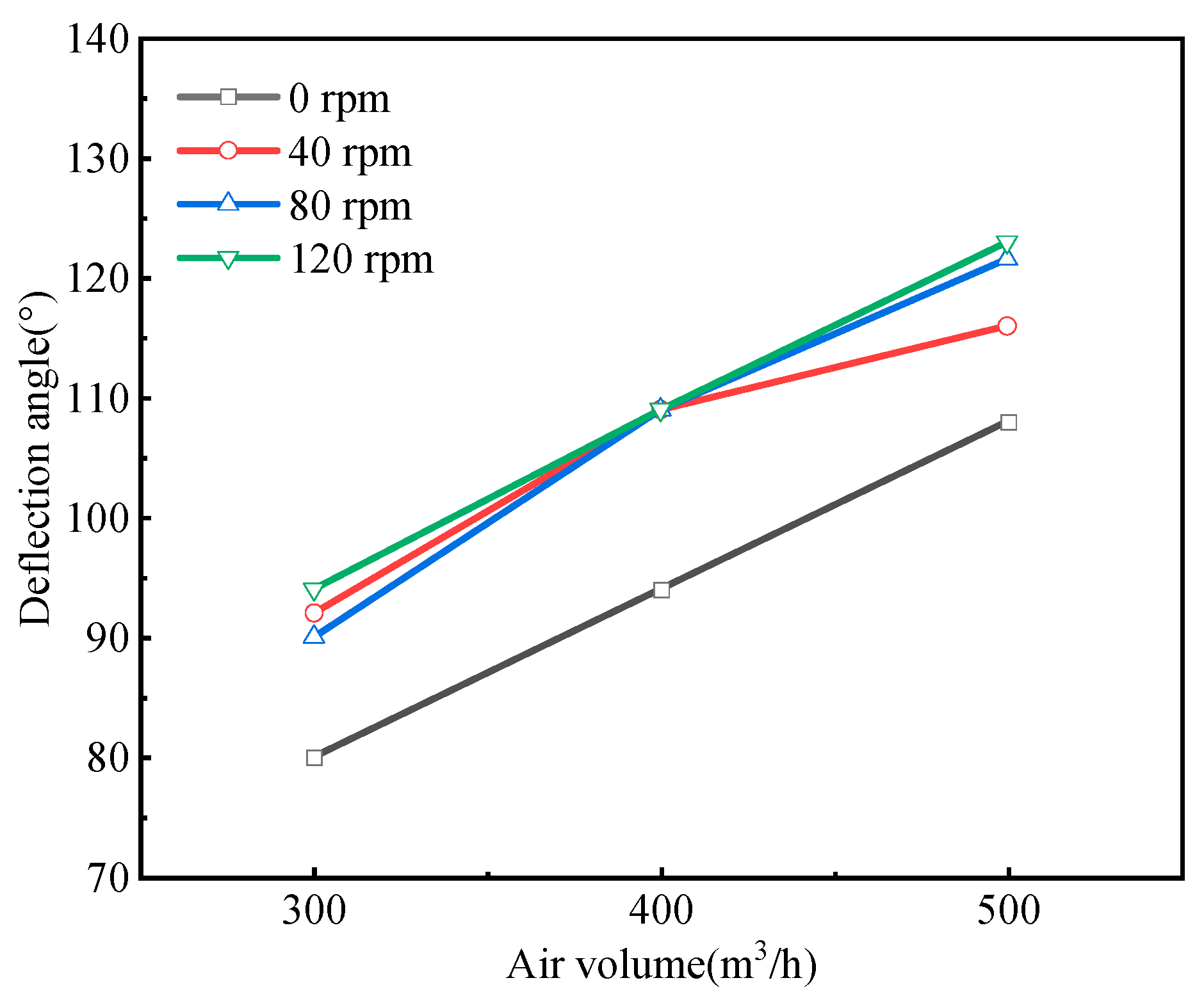
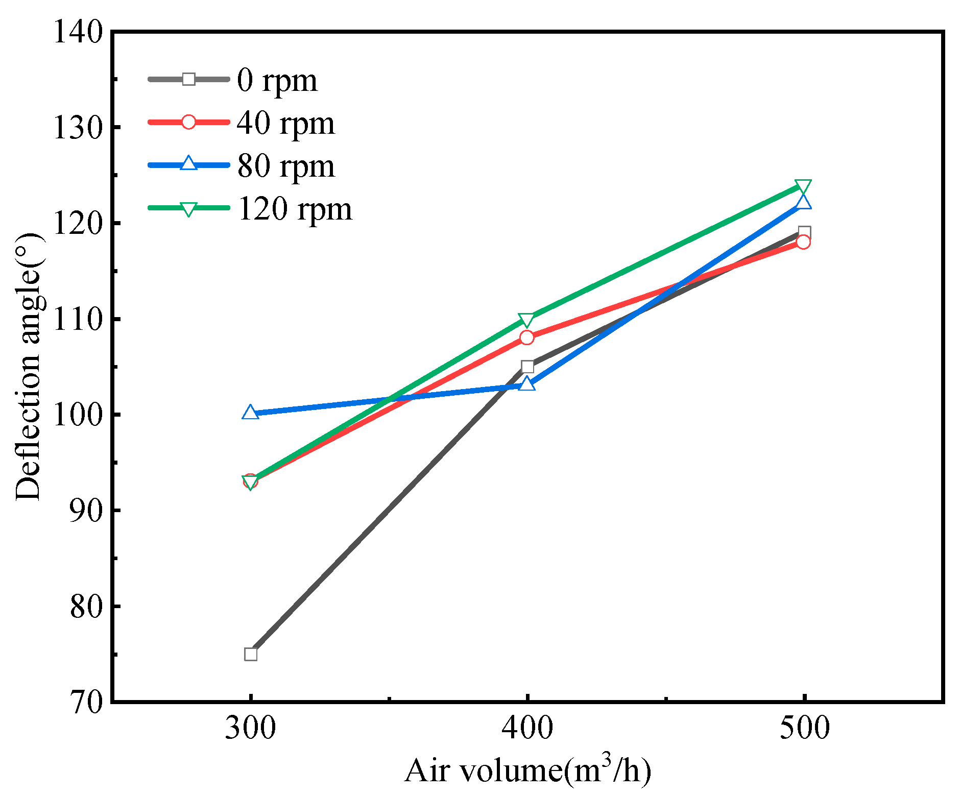
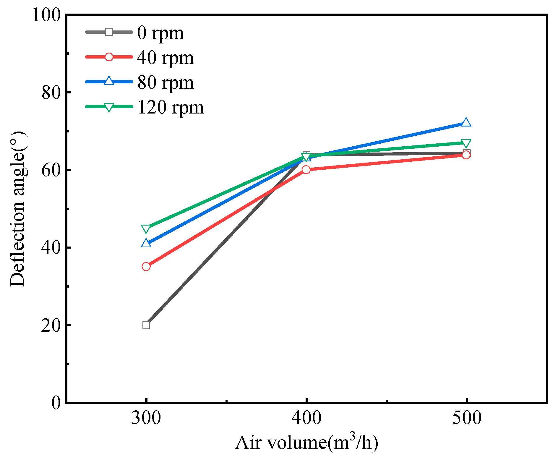
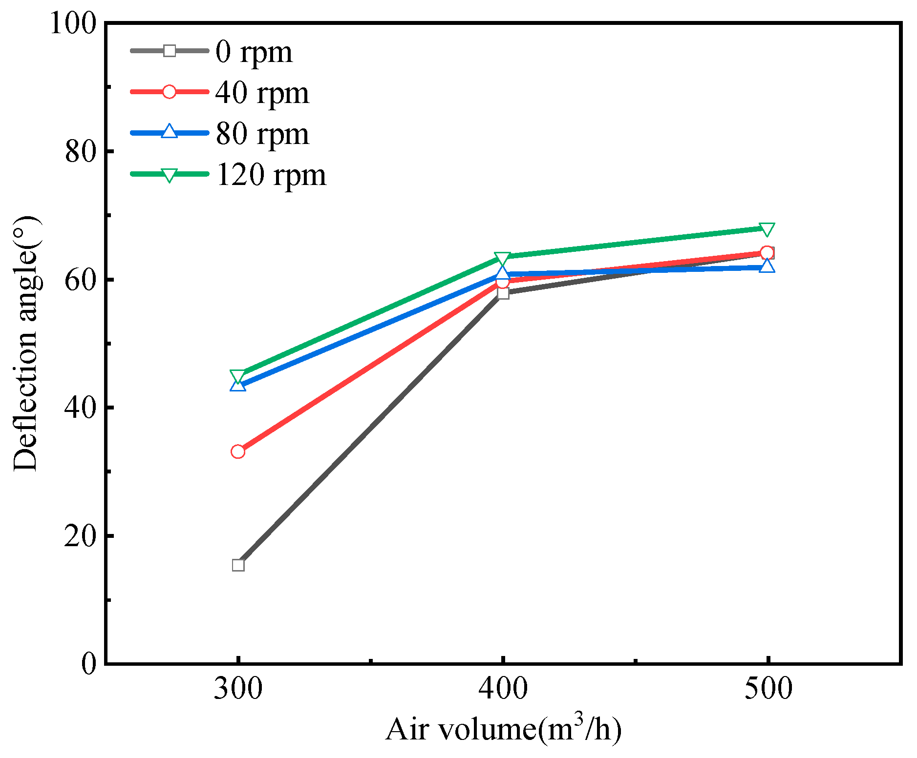
4.1. The Influence of Rotational Speed and Air Volume on Coal Dust Deposition Degree

As depicted in Figure 7 and Figure 8, the deflection angle within the zone of coal dust collection shows an increasing trend as the airflow rises for coal dust with a diameter of 0.1 mm. Moreover, in the absence of drill rod rotation, the deflection angle in the coal dust collection zone is notably lower compared to the situation when the drill rod is in motion. The deflection angle in the coal dust collection zone remains relatively consistent across different rotational speeds, as the speed gradually increases from 40 rpm to 120 rpm when the coal dust generation is 0.24 m3/h. This suggests that the suspension level of 0.1 mm coal dust becomes independent of the rotational speed once it reaches 40 rpm. However, at a coal dust generation of 0.48 m3/h with an airflow setting of 300 m3/h, the rotational speed has a more pronounced impact on the degree of deposition.
As illustrated in Figure 9 and Figure 10, for coal dust with a diameter of 1.69 mm, the deflection angle within the coal dust collection zone amplifies with an increase in airflow. With an air volume of 300 m3/h, elevating the rotational speed results in a substantial enhancement of the deflection angle. Specifically, the deflection angle rises from 20° during stationary drill rod to 46° at 120 rpm, exhibiting a 130% augmentation. However, the influence of raising the rotational speed on the deflection angle becomes obscure when the airflow setting is at 400 m3/h. Under an airflow of 500 m3/h, the deflection angle of the coal dust collection zone rises from 61° during non-rotation of the drill rod to 70° at 120 rpm, representing a 12.8% surge.
From cases 1–24, the volume distributions of various particles exhibit comparable trends. Specifically, particles measuring 0.1 mm are predominantly located in the upper middle, while particles measuring 0.3 mm and 0.75 mm dominate the lower middle region. In addition, particles with an average dimension of 1.69 mm are primarily present at the bottom. The large particle size coal dust particles are more intuitively affected by wind volume and rotational speed. The subsequent section concentrates on the deposition of large particles, given that small particles are amply dispersed throughout all regions.
Upon thorough analysis of the simulation results, it becomes evident that the rotational speed and airflow are the primary factors influencing particle deposition, particularly when the rotational speed exceeds 40 rpm. Meanwhile, coal dust content variations have a minimal impact on deposition within the range considered. At a rotational speed of 80 rpm, deposition occurs when the airflow ranges from 300 to 400 m3/h. However, no deposition is observed at an airflow of 500 m3/h. When the maximum rotational speed of 120 rpm is reached, a small but detectable level of deposition remains at the lowest airflow of 300 m3/h. However, with larger air volumes ranging from 400 to 500 m3/h, no deposition is observed. To effectively prevent deposition, the rotational speed must be 80 rpm or higher when the airflow is 500 m3/h, while a speed of 120 rpm or above is required when the airflow is 400 m3/h. Even at a rotational speed of 120 rpm, there is still a small amount of deposition at the bottom when the airflow is at 300 m3/h. To consider how to control the speed at the lowest airflow, case 25 is added, and it is found that when the speed is up to 200 rpm, there is no deposition of coal dust at the bottom at the lowest airflow.

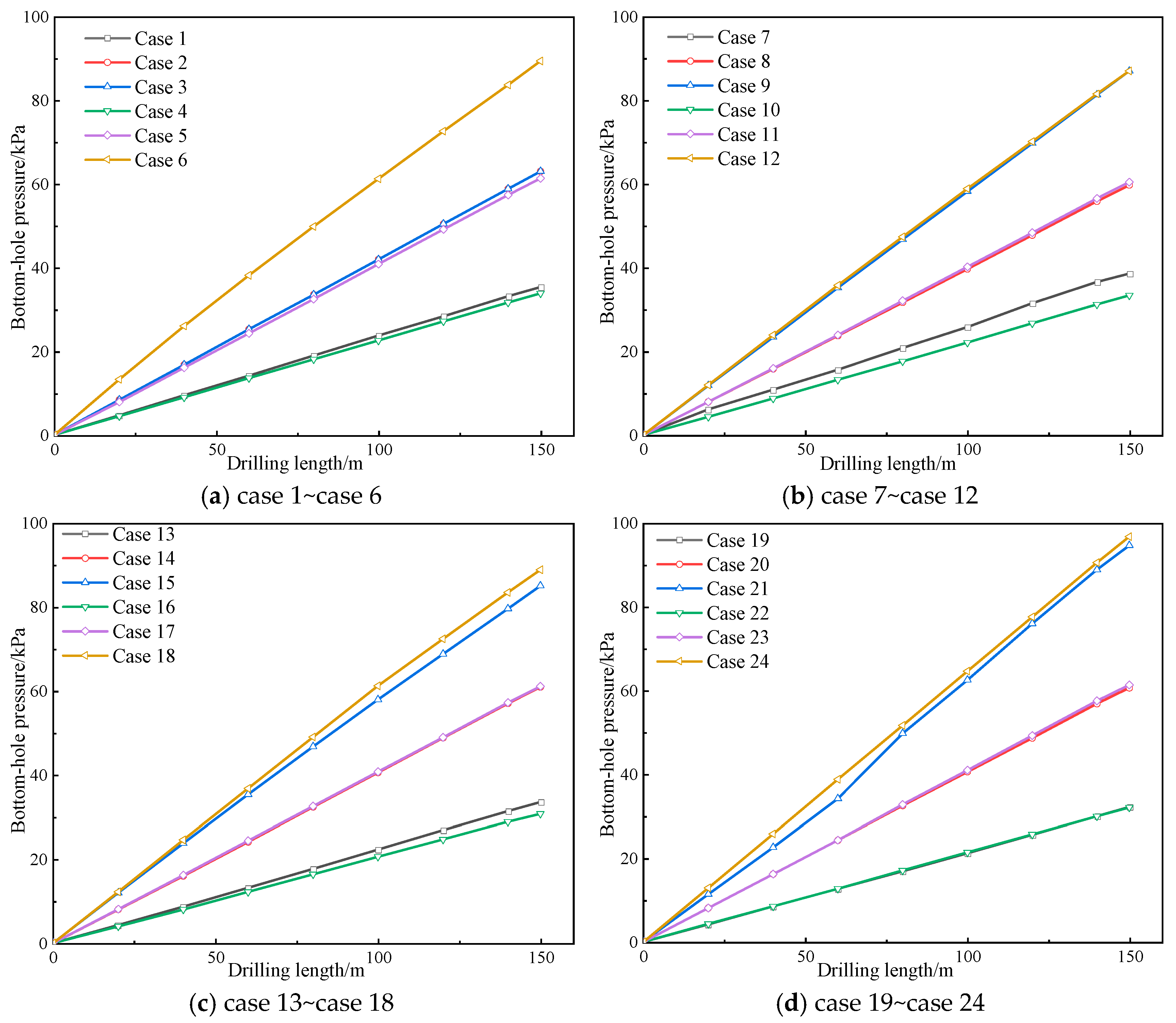
4.2. The Influence of Rotational Speed and Air Volume on the Bottom-Hole Pressure

The relationship between the pressure and the air volume at the bottom of the borehole at different speeds of rotation is shown in Figure 11 and Figure 12.
From the figure presented, it is evident that the pressure at the bottom of the borehole increases as the air volume escalates. However, when the air volume reaches 300 m3/h and 400 m3/h, changes in the rotational speed do not exhibit a significant impact on the bottom-hole pressure. In the case of an air volume of 500 m3/h, there is no apparent difference in the pressure between rotational speeds of 0, 40, and 80 rpm. However, with a rotational speed of 120 rpm, there is a notable increase in the bottom-hole pressure by 10 kPa.
Furthermore, the amount of coal dust generated, whether it be 0.24 m3/h or 0.48 m3/h, does not appear to affect the pressure. Similarly, variations in the coal dust generation, ranging from 0.24 m3/h to 0.48 m3/h, demonstrate a minimal influence on the bottom-hole pressure.

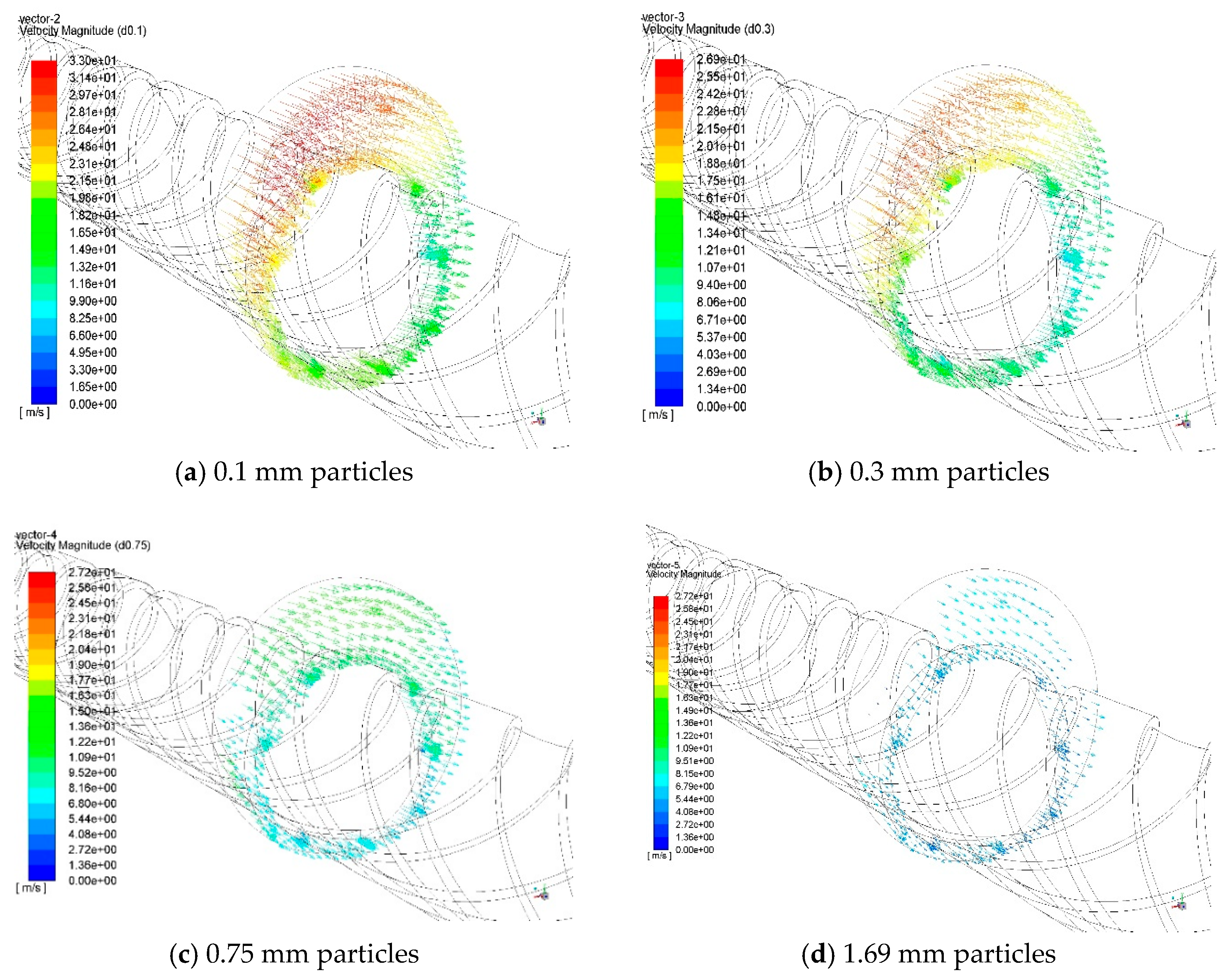
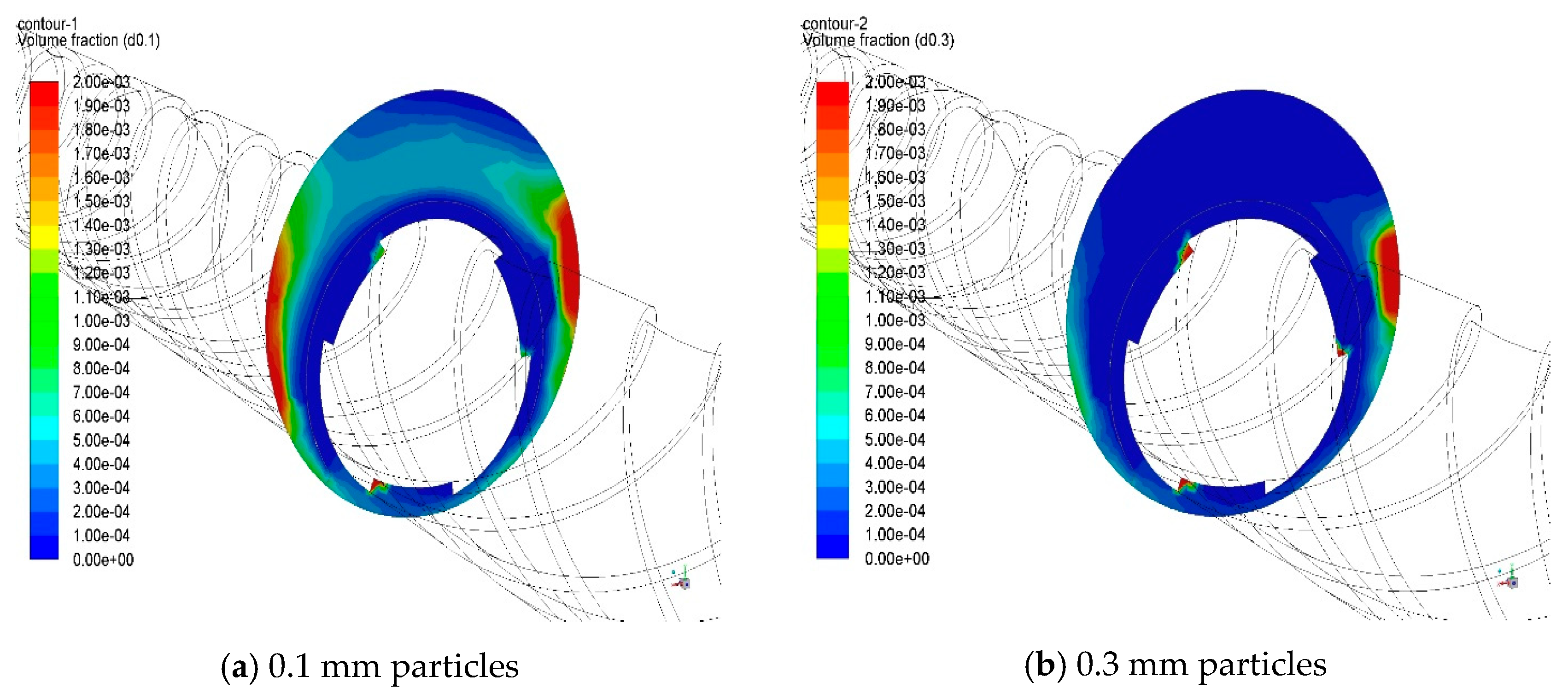
4.3. The Influence of Air Volume and Rotational Speed on the Transportation of Coal Dust

In Figure 13, the trajectory of 0.1 mm coal dust is depicted with an air volume of 300 m3/h and a rotational speed of 0. The various colors of lines in the figure signify the trajectory of coal dust with different particle sizes. As the figure illustrates, in the absence of drill rod rotation, coal dust is suspended in a stabilized state and transported along a particular trajectory line to the porthole. This stable suspension of coal dust is maintained by the aerodynamic forces that are presented in the airflow rate, which carries the mixture of coal and air to the porthole.
The left side of the figure is the borehole bottom, where coal dust is generated alongside the air with some turbulence and disorderly transportation. After undergoing a certain deposition and subsequent resuspension, it eventually reaches a stable state for transport through the orifice.
In Figure 14 and Figure 15, the trajectory and cross-sectional distribution of 0.1 mm coal dust are presented under conditions of an air volume of 400 m3/h and a rotational speed of 80 rpm. As depicted in the figures, when the drill rod rotates at a certain speed, some small coal dust enters a suspended state and follows a specific trajectory line toward the porthole. Meanwhile, other small particles are propelled towards the porthole through a spiraling motion. It is worth noting that larger particles do not exhibit this spiraling transport mode.
The rotational action of the drill rod results in the lifting of small coal dust, with the likelihood of lifting decreasing as the particle size increases. The rotation of the drill rod alters the distribution of the flow field, leading to turbulence. This increased turbulence enhances the suspension of larger particles and facilitates their discharge from the system.

5. Conclusions

A gas–solid two-phase model based on the Eulerian–Eulerian method was used to simulate the transport of coal dust during directional drilling using a screw motor. The statistical data of coal dust particles with different particle sizes, inlet and outlet conditions, specific annular air cross-sections, and different rotational speeds and airflow rates were analyzed. The effects of particle size and airflow on transport characteristics and distribution patterns were elucidated. The complex dynamics of coal dust migration during directional drilling were revealed in depth.
a.
In the case of small coal dust particles, the deposition degree is primarily influenced by the air volume, with the rotation of the drill rod exhibiting some influence. The deposition degree is influenced by both the air volume and the rotational speed for large coal dust particles. For example, in the case of coal dust generation at a rate of 0.24 m3/h, when the drill pipe’s rotational speed increases from 0 to 120 rpm, the deflection angle of the 1.69 mm pulverized coal collection zone increases by 130% under an airflow of 300 m3/h. The degree of coal dust deposition is found to be more influenced by the amount of coal dust generation than by other factors. However, it is worth noting that the impact of coal dust generation on the deposition degree decreases as the particle size increases.
b.
The bottom-hole pressure scales up with the increase in air volume. When the air volume increases from 300 to 500 m3/h, the bottom-hole pressure increases by about 200%, and the change in rotational speed and the rate of coal dust generation does not significantly affect the pressure at the bottom of the borehole. The amount of coal dust production does not affect the pressure.
c.
Coal dust is generated alongside air, and there is turbulence and coal dust mess transport hole section. After a period of deposition and re-suspension, the coal dust reaches a stable state of transport within the borehole. When the drill pipe rotates at a specific speed, small particles of coal dust exhibit a suspended state along a particular trajectory toward the borehole. Some of these particles tumble along the helix path towards the borehole, while larger particles are not observed in this helical mode of transport. Instead, they tend to be primarily located in the middle and lower sections of the borehole, following a certain trajectory towards the outlet for transport.
d.
It is recommended to control the rotational speed of the rotary drilling within the range of 80 to 120 rpm based on the simulation analysis and practical experience of medium-air-pressure drilling. Additionally, the air volume should be set at a minimum of 400 m3/h, preferably up to 500 m3/h. In the case of sliding directional drilling mode, due to the rotational speed being 0, it is crucial to ensure a large airflow volume to reduce sedimentation and maintain a certain amount of debris removal capacity, and the airflow volume should reach 500 m3/h. It is essential to perform full rotary borehole sweeping of dregs to ensure a smooth borehole and construction safety when the airflow volume is less than 400 m3/h.

Author Contributions

Methodology, T.C.; Investigation, T.C.; Resources, J.Z.; Data curation, N.Y.; Writing—original draft, J.Z. and Z.H.; Writing—review and editing, X.Y. and J.C.; Supervision, X.Y. and C.C.; Project administration, J.C.; Funding acquisition, J.C. All authors have read and agreed to the published version of the manuscript.

Funding

This research was funded by the National Natural Science Foundation of China (No. 42002311).

Data Availability Statement

Data are contained within the article.

Conflicts of Interest

The authors declare no conflicts of interest.

References

  1. Hu, S.; Cheng, Y. Discussions on key development fields of China’s coal science and technology at an early stage of the 21st century. J. China Coal Soc. 2005, 30, 1–7. [Google Scholar]
  2. Liu, C. Failure Characteristics and Control Technology Basis of Collapsed Hole Failure in Soft Coal Seam Gas Extraction Drilling. Ph.D. Thesis, China University of Mining and Technology, Xuzhou, China, 2014. [Google Scholar]
  3. Li, K.; Ting, R.; Yao, Y. Key technology of automatic loading and unloading system for dual-pipe directional drilling rig and its application in soft-fragmentized coal seam. Coal Geol. Explor. 2023, 51, 179–186. [Google Scholar]
  4. Zhang, H.; Zhang, J.; Yang, S.; Wang, C.; Zhang, Y.; Wang, J.; Yang, Z. Experimental study on directional drilling technology of high spiral composite slag discharge in broken soft coal seam. Coal Eng. 2022, 54, 62–67. [Google Scholar]
  5. Sun, L. Minimum wind flow of air directional drilling technology in soft-fragmentized coal seam. Saf. Coal Mines 2021, 52, 175–180. [Google Scholar]
  6. Nie, C.; Wang, Y.; Yao, Y.; Hong, J. Powder discharge characteristics of pneumatic double pipe directional drilling in broken soft coal seams and its application. Coal Geol. Explor. 2022, 50, 159–166. [Google Scholar]
  7. Xin, D.; Tang, M.; Liu, X. Development and application of automatic drilling rig for bedding in broken soft coal seam. Min. Saf. Environ. Prot. 2022, 49, 24–28. [Google Scholar]
  8. Wang, L. Techniques of double-pipe and double-acting directional drilling with air in broken and soft coal seams in underground coal mines. Coal Geol. Explor. 2022, 50, 166–172. [Google Scholar]
  9. Long, W.; Sun, S.; Chen, J. Study on long-distance fixed-point sealed coring technology in broken-soft coal seam. Coal Geol. Explor. 2022, 50, 93–98. [Google Scholar]
  10. Sun, Y.; Zhang, J.; Ma, Q.; Huang, H.; Zhang, Y.; Wang, J. Experimental study on directional drilling with high pressure nitrogen in soft-fragmentized coal seam of Wangpo Coal Mine. Saf. Coal Mines 2022, 53, 64–69. [Google Scholar]
  11. Wen, Z. Directional drilling technology for high spiral composite slag discharge in broken soft coal seams. Shandong Coal Sci. Technol. 2023, 41, 78–80. [Google Scholar]
  12. Xu, Y.; Zhu, Y.; Zhang, P. Application of CBM horizontal well development technology in the roof strata close to broken-soft coal seams. Nat. Gas Ind. 2018, 38, 168–174. [Google Scholar] [CrossRef]
  13. Long, W. Trace and determination of the gas compositional difference in the coal seam gas content testing. J. Saf. Environ. 2020, 20, 925–929. [Google Scholar]
  14. Yuan, L. Theory and Practice of Integrated Pillarless Coal Production and Methane Extraction in Multiseams of Low Permeability; China Coal Industry Publishing House: Beijing, China, 2008; pp. 10–18. [Google Scholar]
  15. Kremieniewski, M.; Rzepka, M. Przyczyny i skutki przepływu gazu w zacementowanej przestrzeni pierścieniowej otworu wiertniczego oraz metody zapobiegania temu zjawisku. Nafta-Gaz 2016, 72, 722–728. [Google Scholar] [CrossRef]
  16. Cheng, Y.; Wang, L.; Zhang, X. Environmental impact of coal mine methane emissions and responding strategies in China. Int. J. Greenh. Gas Control 2011, 5, 157–166. [Google Scholar] [CrossRef]
  17. Wang, L.; Yao, N.; Yao, Y.; Wang, Y.; Zhang, J.; Fang, J.; Wei, H. Research progress of drilling and borehole completion technologies in broken soft coal seam in underground coal mines. Coal Geol. Explor. 2021, 49, 285–296. [Google Scholar]
  18. Ji, Q.; Dong, M.; Liu, J.; Shi, L. Foam drilling technology and application for broken soft coal seam in underground coal mine. Coal Geol. Explor. 2020, 48, 25–29. [Google Scholar]
  19. Ma, D.; Wang, Y. Study and application on influencing factors of pneumatic directional drilling in broken soft coal seam. Coal Technol. 2023, 42, 79–84. [Google Scholar]
  20. Cao, X. Research on application of in-seam air directional drilling under complex working conditions. Drill. Eng. 2023, 50, 150–154. [Google Scholar]
  21. Liu, X.; Wang, L.; Wang, J.; Huang, H.; Song, C.; Wang, J. Research and practices on drilling in soft coal seams in Hancheng Sangshuping coal mine. Coal Geol. Explor. 2017, 45, 165–169. [Google Scholar]
  22. Zhang, Z.; Sun, Y.; Fu, Y.; Wang, T. Study and application of pre-reinforcement of soft and breaking coal mass in gas drainage drilling field. Coal Eng. 2019, 51, 44–47. [Google Scholar]
  23. Behera, N.; Agarwal, V.K.; Jones, M.G.; Williams, K.C. CFD modeling and analysis of dense phase pneumatic conveying of fine particles including particle size distribution. Powder Technol. 2013, 244, 30–37. [Google Scholar] [CrossRef]
  24. Pu, W.; Zhao, C.; Xiong, Y.; Liang, C. Numerical simulation on dense phase pneumatic conveying of coal dust in horizontal pipe at high pressure. Chem. Eng. Sci. 2010, 65, 2500–2512. [Google Scholar] [CrossRef]
  25. Khormali, A. Effect of water cut on the performance of an asphaltene inhibitor package: Experimental and modeling analysis. Pet. Sci. Technol. 2022, 40, 2890–2906. [Google Scholar] [CrossRef]
  26. Ji, Q.; Ying, X.; Wang, Y. Experiment on technical parameters of air drilling in floppy coal seam. Coal Geol. Explor. 2009, 37, 78–80. [Google Scholar]
  27. Nie, C.; Wang, Y.; Yao, Y. Numerical simulation of coal dust migration law in air directional drilling in broken soft coal seam. Saf. Coal Mines 2022, 53, 175–180. [Google Scholar]
  28. Zhao, K.; Lu, H.; Guo, X.; Gong, X. Vertical pneumatic conveying of two industrial coal dusts with different particle sizes. J. Chem. Eng. Chin. Univ. 2018, 32, 994–1003. [Google Scholar]
  29. Dai, J.; Ding, X.; Xu, H.; Liu, C.; Ju, T. Numerical simulation of conveying characteristics of dense phase coal dust in bend pipe. J. Iron Steel Res. 2020, 32, 377–385. [Google Scholar]
  30. Adewumi, M.A.; Tian, S. Determination of optimal air flow rate in air drilling. Pet. Sci. Eng. 1992, 8, 1–11. [Google Scholar] [CrossRef]
  31. Wang, C.; Lu, H.; Guo, X.; Liu, H.; Gong, X. Flow characteristics of dense phase pneumatic conveying of coal dust through the bend. J. East China Univ. Sci. Technol. 2021, 47, 676–683. [Google Scholar]
  32. Khan, T.S.; Dai, Y.; Alshehhi, M.S.; Khezzar, L. Experimental flow characterization of sand particles for pneumatic transport in horizontal circular pipes. Powder Technol. 2016, 292, 158–168. [Google Scholar] [CrossRef]
Figure 1. System-wide network diagram.
Processes 12 00309 g001
Figure 2. Schematic diagram of deflection angle in coal dust collection zone.
Processes 12 00309 g002
Figure 3. Variation in borehole bottom pressure distribution pattern with borehole length.
Processes 12 00309 g003
Figure 4. Velocity distribution of cross-section of case 24.
Processes 12 00309 g004
Figure 5. Particle volume fraction distribution of case 24.
Processes 12 00309 g005aProcesses 12 00309 g005b
Figure 6. Particle trajectory distribution of case 24.
Processes 12 00309 g006
Figure 7. A 0.1 mm particulate collection zone deflection angle (coal dust generation at a rate of 0.24 m3/h).
Processes 12 00309 g007
Figure 8. A 0.1 mm particulate collection zone deflection angle (coal dust generation at a rate of 0.48 m3/h).
Processes 12 00309 g008
Figure 9. A 1.69 mm particulate collection zone deflection angle (coal dust generation at a rate of 0.24 m3/h).
Processes 12 00309 g009
Figure 10. A 1.69 mm particulate collection zone deflection angle (coal dust generation at a rate of 0.48 m3/h).
Processes 12 00309 g010
Figure 11. The plot of pressure at the borehole bottom versus air volume (coal dust generation at a rate of 0.24 m3/h).
Processes 12 00309 g011
Figure 12. The plot of pressure at the borehole bottom versus air volume (coal dust generation at a rate of 0.48 m3/h).
Processes 12 00309 g012
Figure 13. The trajectory of 0.1 mm coal dust at an air volume of 300 m3/h and a rotational speed of 0.
Processes 12 00309 g013
Figure 14. The trajectory of 0.1 mm coal dust at an air volume of 400 m3/h and a rotational speed of 80 rpm.
Processes 12 00309 g014
Figure 15. Cross-sectional distribution of 0.1 mm coal dust at an air volume of 400 m3/h and a rotational speed of 80 rpm.
Processes 12 00309 g015
Table 1. Particle distribution.
Particle Size/mm0.10.30.751.69
Percentage/%46221616
Table 2. Numerical simulation cases in consideration of revolutions per minute, air volume, and the volume fraction of coal dust.
CasesABCCasesABC
Case 103000.08Case 14804000.06
Case 204000.06Case 15805000.05
Case 305000.05Case 16803000.16
Case 403000.16Case 17804000.12
Case 504000.12Case 18805000.1
Case 605000.1Case 191203000.08
Case 7403000.08Case 201204000.06
Case 8404000.06Case 211205000.05
Case 9405000.05Case 221203000.16
Case 10403000.16Case 231204000.12
Case 11404000.12Case 241205000.1
Case 12405000.1Case 252003000.16
Case 13803000.08
A: revolutions per minute B: air volume (m3/h) C: the volume fraction of coal dust (%).
Disclaimer/Publisher’s Note: The statements, opinions and data contained in all publications are solely those of the individual author(s) and contributor(s) and not of MDPI and/or the editor(s). MDPI and/or the editor(s) disclaim responsibility for any injury to people or property resulting from any ideas, methods, instructions or products referred to in the content.

