
Development of a Molecular Dynamics Model to Assess the Possibility of Type II/III Porous Liquid Formation


Abstract
1. Introduction
2. Modeling
Measuring Open Porosity
3. Results and Discussion
3.1. Model Validation
3.2. MD Model
4. Conclusions
Author Contributions
Funding
Data Availability Statement
Conflicts of Interest
References
- Seader, J.D.; Henley, E.J.; Roper, D.K. Separation Process Principles; Wiley: New York, NY, USA, 1998; Volume 25. [Google Scholar]
- Yaumi, A.L.; Bakar, M.Z.A.; Hameed, B.H. Recent advances in functionalized composite solid materials for carbon dioxide capture. Energy 2017, 124, 461–480. [Google Scholar] [CrossRef]
- Giri, N.; Del Pópolo, M.G.; Melaugh, G.; Greenaway, R.L.; Rätzke, K.; Koschine, T.; Pison, L.; Gomes, M.F.C.; Cooper, A.I.; James, S.L. Liquids with permanent porosity. Nature 2015, 527, 216–220. [Google Scholar] [CrossRef]
- Zhang, J.; Chai, S.H.; Qiao, Z.A.; Mahurin, S.M.; Chen, J.; Fang, Y.; Wan, S.; Nelson, K.; Zhang, P.; Dai, S. Porous liquids: A promising class of media for gas separation. Angew. Chem. 2015, 127, 946–950. [Google Scholar] [CrossRef]
- Bates, E.D.; Mayton, R.D.; Ntai, I.; Davis, J.H. CO2 Capture by a Task-Specific Ionic Liquid. J. Am. Chem. Soc. 2002, 124, 926–927. [Google Scholar] [CrossRef]
- Abánades Lázaro, I.; Haddad, S.; Sacca, S.; Orellana-Tavra, C.; Fairen-Jimenez, D.; Forgan, R.S. Selective Surface PEGylation of UiO-66 Nanoparticles for Enhanced Stability, Cell Uptake, and pH-Responsive Drug Delivery. Chem 2017, 2, 561–578. [Google Scholar] [CrossRef]
- Siegel, R.W.; Hu, E.; Cox, D.M.; Goronkin, H.; Jelinski, L.; Koch, C.C.; Mendel, J.; Roco, M.C.; Shaw, D.T. (Eds.) Nanostructure Science and Technology: R&D Status and Trends in Nanoparticles, Nanostructured Materials, and Nanodevices; Springer: Dordrecht, The Netherlands, 1999; pp. 49–66. [Google Scholar]
- Armand, M.; Endres, F.; MacFarlane, D.R.; Ohno, H.; Scrosati, B. Ionic-liquid materials for the electrochemical challenges of the future. Nat. Mater. 2009, 8, 621–629. [Google Scholar] [CrossRef]
- Zhang, F. Thermodynamics and kinetics of gas storage in porous liquids. Phys. Chem. B 2016, 120, 7195–7200. [Google Scholar] [CrossRef]
- Greenaway, R.L.; Holden, D.; Eden, E.G.; Stephenson, A.; Yong, C.W.; Bennison, M.J.; Hasell, T.; Briggs, M.E.; James, S.L.; Cooper, A.I. Understanding gas capacity, guest selectivity, and diffusion in porous liquids. Chem. Sci. 2017, 8, 2640–2651. [Google Scholar] [CrossRef]
- Fulvio, P.F.; Dai, S. Porous liquids: The next frontier. Chem 2020, 6, 3263–3287. [Google Scholar] [CrossRef]
- O’Reilly, N.; Giri, N.; James, S.L. Porous liquids. Chem. Eur. J. 2007, 13, 3020–3025. [Google Scholar] [CrossRef]
- Alexander, F.M.; Fonrouge, S.F.; Borioni, J.L.; Del Pópolo, M.G.; Horton, P.N.; Coles, S.J.; Hutchings, B.P.; Crawford, D.E.; James, S.L. Noria and its derivatives as hosts for chemically and thermally robust Type II porous liquids. Chem. Sci. 2021, 12, 14230–14240. [Google Scholar] [CrossRef]
- Wang, D.; Xin, Y.; Yao, D.; Li, X.; Ning, H.; Zhang, H.; Wang, Y.; Ju, X.; He, Z.; Yang, Z. Shining light on porous liquids: From fundamentals to syntheses, applications and future challenges. Adv. Funct. Mater. 2022, 32, 2104162. [Google Scholar] [CrossRef]
- Dinker, M.K.; Zhao, K.; Liu, S.; Qi, S.-C.; Li, Y.-X.; Liu, G.-P.; Ding, L.; Liu, X.-Q.; Sun, L.-B. Permanent cavities in ionic liquids created by metal–organic polyhedra. J. Mater. Chem. A 2022, 10, 16204–16211. [Google Scholar] [CrossRef]
- Hasell, T.; Cooper, A.I. Porous organic cages: Soluble, modular and molecular pores. Nat. Rev. Mater. 2016, 1, 16053. [Google Scholar] [CrossRef]
- Ma, L.; Haynes, C.J.; Grommet, A.B.; Walczak, A.; Parkins, C.C.; Doherty, C.M.; Longley, L.; Tron, A.; Stefankiewicz, A.R.; Bennett, T.D. Coordination cages as permanently porous ionic liquids. Nat. Chem. 2020, 12, 270–275. [Google Scholar] [CrossRef]
- Jie, K.; Onishi, N.; Schott, J.A.; Popovs, I.; Jiang, D.E.; Mahurin, S.; Dai, S. Transforming porous organic cages into porous ionic liquids via a supramolecular complexation strategy. Angew. Chem. 2020, 132, 2288–2292. [Google Scholar] [CrossRef]
- Li, H.; Liu, B.; Yang, M.; Zhu, D.; Huang, Z.; Chen, W.; Yang, L.; Chen, G. CO2 separation performance of zeolitic imidazolate framework-8 porous slurry in a pilot-scale packed tower. Ind. Eng. Chem. Res. 2020, 59, 6154–6163. [Google Scholar] [CrossRef]
- Boventi, M.; Mauri, M.; Alexander, F.; James, S.L.; Simonutti, R.; Castiglione, F. Exploring cavities in Type II porous liquids with xenon. J. Mol. Liq. 2023, 370, 121038. [Google Scholar] [CrossRef]
- Smith, S.J.; Wood, C.D.; Feron, P.H.; Mahdavi, H.; Mulder, R.J.; Doherty, C.M.; Hill, M.R.; Mulet, X. Porous solid inspired hyper-crosslinked polymer liquids with highly efficient regeneration for gas purification. Sci. China Mater. 2022, 65, 1937–1942. [Google Scholar] [CrossRef]
- Hosseini Monjezi, B.; Kutonova, K.; Tsotsalas, M.; Henke, S.; Knebel, A. Current trends in metal–organic and covalent organic framework membrane materials. Angew. Chem. Int. Ed. 2021, 60, 15153–15164. [Google Scholar] [CrossRef]
- Mahdavi, H.; Eden, N.T.; Doherty, C.M.; Acharya, D.; Smith, S.J.; Mulet, X.; Hill, M.R. Underlying Polar and Nonpolar Modification MOF-Based Factors that Influence Permanent Porosity in Porous Liquids. ACS Appl. Mater. Interfaces 2022, 14, 23392–23399. [Google Scholar] [CrossRef]
- Shan, W.; Fulvio, P.F.; Kong, L.; Schott, J.A.; Do-Thanh, C.-L.; Tian, T.; Hu, X.; Mahurin, S.M.; Xing, H.; Dai, S. New class of type III porous liquids: A promising platform for rational adjustment of gas sorption behavior. ACS Appl. Mater. Interfaces 2018, 10, 32–36. [Google Scholar] [CrossRef]
- Cahir, J.; Tsang, M.Y.; Lai, B.; Hughes, D.; Alam, M.A.; Jacquemin, J.; Rooney, D.; James, S.L. Type 3 porous liquids based on non-ionic liquid phases–a broad and tailorable platform of selective, fluid gas sorbents. Chem. Sci. 2020, 11, 2077–2084. [Google Scholar] [CrossRef]
- Bavykina, A.; Cadiau, A.; Gascon, J. Porous liquids based on porous cages, metal organic frameworks and metal organic polyhedra. Coord. Chem. Rev. 2019, 386, 85–95. [Google Scholar] [CrossRef]
- Nakanishi, T. Functional Organic Liquids; John Wiley & Sons: Hoboken, NJ, USA, 2019. [Google Scholar]
- Mahdavi, H.; Smith, S.J.; Mulet, X.; Hill, M.R. Practical considerations in the design and use of porous liquids. Mater. Horiz. 2022, 9, 1577–1601. [Google Scholar] [CrossRef]
- Mahdavi, H.; Sadiq, M.M.; Smith, S.J.D.; Mulet, X.; Hill, M.R. Underlying potential evaluation of the real-process applications of magnetic porous liquids. J. Mater. Chem. A 2023, 11, 16846–16853. [Google Scholar] [CrossRef]
- Mukesh, C.; Sarmad, S.; Samikannu, A.; Nikjoo, D.; Siljebo, W.; Mikkola, J.-P. Pore size-excluded low viscous porous liquids for CO2 sorption at room temperature and thermodynamic modeling study. J. Mol. Liq. 2022, 356, 119046. [Google Scholar] [CrossRef]
- Mahdavi, H.; Zhang, H.; Macreadie, L.K.; Doherty, C.; Acharya, D.; Smith, S.J.; Mulet, X.; Hill, M.R. Underlying solvent-based factors that influence permanent porosity in porous liquids. Nano Res. 2022, 15, 3533–3538. [Google Scholar] [CrossRef]
- Kunde, T.; Pausch, T.; Schmidt, B.M. Porous Organic Compounds—Small Pores on the Rise. Eur. J. Org. Chem. 2021, 2021, 5844–5856. [Google Scholar] [CrossRef]
- Kearsey, R.J.; Alston, B.M.; Briggs, M.E.; Greenaway, R.L.; Cooper, A.I. Accelerated robotic discovery of type II porous liquids. Chem. Sci. 2019, 10, 9454–9465. [Google Scholar] [CrossRef]
- Liu, H.; Liu, B.; Lin, L.-C.; Chen, G.; Wu, Y.; Wang, J.; Gao, X.; Lv, Y.; Pan, Y.; Zhang, X. A hybrid absorption–adsorption method to efficiently capture carbon. Nat. Commun. 2014, 5, 5147. [Google Scholar] [CrossRef]
- Atilhan, M.; Cincotti, A.; Aparicio, S. Nanoscopic characterization of type II porous liquid and its use for CO2 absorption from molecular simulation. J. Mol. Liq. 2021, 330, 115660. [Google Scholar] [CrossRef]
- Horstmann, R.; Hecht, L.; Kloth, S.; Vogel, M. Structural and Dynamical Properties of Liquids in Confinements: A Review of Molecular Dynamics Simulation Studies. Langmuir 2022, 38, 6506–6522. [Google Scholar] [CrossRef]
- Melaugh, G.; Giri, N.; Davidson, C.E.; James, S.L.; Del Pópolo, M.G. Designing and understanding permanent microporosity in liquids. Phys. Chem. Chem. Phys. 2014, 16, 9422–9431. [Google Scholar] [CrossRef]
- Costa Gomes, M.; Pison, L.; Červinka, C.; Padua, A. Porous ionic liquids or liquid metal–organic frameworks? Angew. Chem. 2018, 130, 12085–12088. [Google Scholar] [CrossRef]
- Sheng, L.; Chen, Z.; Wang, Y. Molecular dynamics simulations of stability and fluidity of porous liquids. Appl. Surf. Sci. 2021, 536, 147951. [Google Scholar] [CrossRef]
- Sheng, L.; Chen, Z.; Xu, B.; Shi, J. Molecular dynamics study of the dispersion stability and fluidity of porous liquids with different canopy structures. J. Phys. Chem. B. 2021, 125, 5387–5396. [Google Scholar] [CrossRef]
- Avila, J.; Červinka, C.; Dugas, P.Y.; Pádua, A.A. Costa Gomes, M. Porous ionic liquids: Structure, stability, and gas absorption mechanisms. Adv. Mater. Interfaces 2021, 8, 2001982. [Google Scholar] [CrossRef]
- Zhao, X.; Ding, Y.; Ma, L.; Zhu, X.; Wang, H.; Cheng, M.; Liao, Q. A molecular dynamic insight into CO2 diffusion of type III porous liquids. J. Mol. Liq. 2023, 389, 122731. [Google Scholar] [CrossRef]
- Mahdavi, H.; Burdloff, J.; Robin, A.; Smith, S.J.D.; Mulet, X.; Hill, M.R. Accelerated Systematic Investigation of Solvents Suitability for Type II/III Porous Liquids. ACS Mater. Lett. 2023, 5, 549–557. [Google Scholar] [CrossRef]
- Vendite, A.C.; Soares, T.A.; Coutinho, K. The Effect of Surface Composition on the Selective Capture of Atmospheric CO2 by ZIF Nanoparticles: The Case of ZIF-8. J. Chem. Inf. Model. 2022, 62, 6530–6543. [Google Scholar] [CrossRef]
- Mohan, V.; Smith, P.E.; Pettitt, B.M. Molecular dynamics simulation of ions and water around triplex DNA. J. Phys. Chem. 1993, 97, 12984–12990. [Google Scholar] [CrossRef]
- Zhang, X.; Yi, H.; Zhao, Y.; Min, F.; Song, S. Study on the differences of Na-and Ca-montmorillonites in crystalline swelling regime through molecular dynamics simulation. J. Phys. Chem. 2016, 27, 779–785. [Google Scholar] [CrossRef]
- Addicoat, M.A.; Vankova, N.; Akter, I.F.; Heine, T. Extension of the Universal Force Field to Metal–Organic Frameworks. J. Chem. Theory Comput. 2014, 10, 880–891. [Google Scholar] [CrossRef]
- Zhao, X.; Ding, Y.; Ma, L.; Zhu, X.; Wang, H.; Liao, Q. An enhancement of CO2 capture in a type-III porous liquid by 2-Methylimidazole zinc salt (ZIF-8). J. Mol. Liq. 2022, 367, 120523. [Google Scholar] [CrossRef]
- Parkes, M.V.; Demir, H.; Teich-McGoldrick, S.L.; Sholl, D.S.; Greathouse, J.A.; Allendorf, M.D. Molecular dynamics simulation of framework flexibility effects on noble gas diffusion in HKUST-1 and ZIF-8. Microporous Mesoporous Mater. 2014, 194, 190–199. [Google Scholar] [CrossRef]
- Paudel, H.P.; Shi, W.; Hopkinson, D.; Steckel, J.A.; Duan, Y. Engineering. Computational modelling of adsorption and diffusion properties of CO2 and CH4 in ZIF-8 for gas separation applications: A density functional theory approach. React. Chem. Eng. 2021, 6, 990–1001. [Google Scholar] [CrossRef]
- Zhao, L.; Yang, Q.; Ma, Q.; Zhong, C.; Mi, J.; Liu, D. A force field for dynamic Cu-BTC metal-organic framework. J. Mol. Model. 2011, 17, 227–234. [Google Scholar] [CrossRef]
- Rappé, A.K.; Casewit, C.J.; Colwell, K.; Goddard III, W.A.; Skiff, W.M. UFF, a full periodic table force field for molecular mechanics and molecular dynamics simulations. J. Am. Chem. Soc. 1992, 114, 10024–10035. [Google Scholar] [CrossRef]
- Sheng, L.; Chen, Z. Molecular dynamics study of dispersion and fluidity of porous liquids with different pore sizes. J. Mol. Liq. 2021, 333, 115890. [Google Scholar] [CrossRef]
- Zhang, X.; Huang, T.; Shan, T.; Yuan, Q.; Yin, S.; Li, J.; Wu, Q.; Zhang, P. Molecular dynamics study of the influence of water molecular phase state on the replacement of CO2–CH4 hydrate in porous media. J. Mol. Liq. 2023, 391, 123401. [Google Scholar] [CrossRef]
- Islam, M.A.; Rony, M.D.; Hasan, M.N. Thin film liquid-vapor phase change phenomena over nano-porous substrates: A molecular dynamics perspective. Heliyon 2023, 9, e15714. [Google Scholar] [CrossRef]
- Ferreira, P.H.L.; Sampaio, A.M.; Siqueira, L.J.A. Energy and power performances of binary mixtures of ionic liquids in planar and porous electrodes by molecular dynamics simulations. Electrochim. Acta 2022, 410, 139982. [Google Scholar] [CrossRef]
- Liu, X.; Li, Y.; Ban, Y.; Peng, Y.; Jin, H.; Bux, H.; Xu, L.; Caro, J.; Yang, W. Improvement of hydrothermal stability of zeolitic imidazolate frameworks. Chem. Commun. 2013, 49, 9140–9142. [Google Scholar] [CrossRef]
- Zhang, H.; Zhao, M.; Lin, Y.S. Stability of ZIF-8 in water under ambient conditions. Microporous Mesoporous Mater. 2019, 279, 201–210. [Google Scholar] [CrossRef]
- Morris, W.; Stevens, C.J.; Taylor, R.E.; Dybowski, C.; Yaghi, O.M.; Garcia-Garibay, M.A. NMR and X-ray Study Revealing the Rigidity of Zeolitic Imidazolate Frameworks. J. Phys. Chem. C 2012, 116, 13307–13312. [Google Scholar] [CrossRef]
- Moghadam, P.Z.; Li, A.; Wiggin, S.B.; Tao, A.; Maloney, A.G.P.; Wood, P.A.; Ward, S.C.; Fairen-Jimenez, D. Development of a Cambridge Structural Database Subset: A Collection of Metal–Organic Frameworks for Past, Present, and Future. Chem. Mater. 2017, 29, 2618–2625. [Google Scholar] [CrossRef]
- Xiang, S.; Zhou, W.; Gallegos, J.M.; Liu, Y.; Chen, B. Exceptionally High Acetylene Uptake in a Microporous Metal–Organic Framework with Open Metal Sites. J. Am. Chem. Soc. 2009, 131, 12415–12419. [Google Scholar] [CrossRef]
- Lyons, M.A.; Reisfeld, B.; Yang, R.S.; Lenaerts, A.J. A physiologically based pharmacokinetic model of rifampin in mice. Antimicrob. Agents Chemother. 2013, 57, 1763–1771. [Google Scholar] [CrossRef]
- Budavari, S.; O’Neil, M.; Smith, A.; Heckelman, P.; Kinneary, J. The Merk Index. An Encyclopedia of Chemicals, Drugs and Biologicals, 13th ed.; Merck and Co., Inc.: Whitehouse Station, NJ, USA, 2001; Volume 1097, p. 1946. [Google Scholar]
- Haynes, W. CRC Handbook of Chemistry and Physics, 94th ed.; Internet Version; Taylor & Francis: Boca Raton, FL, USA, 2014. [Google Scholar]
- Guard, U.C. Chemical Hazard Response Information System (CHRIS)-Hazardous Chemical Data; Technical Report Commandant Instruction 16465.12C; Department of Transportation: Washington, DC, USA, 1999. [Google Scholar]
- Bruno, T.J.; Fortin, T.J.; Lovestead, T.M.; Widegren, J.A. Chemical and thermophysical characterization of 1,3,5-triisopropylcyclohexane. J. Chem. Eng. Data 2012, 57, 2343–2349. [Google Scholar] [CrossRef]
- Rajabpour, A.; Akizi, F.Y.; Heyhat, M.M.; Gordiz, K. Molecular dynamics simulation of the specific heat capacity of water-Cu nanofluids. Int. Nano Lett. 2013, 3, 58. [Google Scholar] [CrossRef]
- Sann, E.E.; Pan, Y.; Gao, Z.; Zhan, S.; Xia, F.J. Highly hydrophobic ZIF-8 particles and application for oil-water separation. Sep. Purif. Technol. 2018, 206, 186–191. [Google Scholar] [CrossRef]
- Yuan, J.; Li, Q.; Shen, J.; Huang, K.; Liu, G.; Zhao, J.; Duan, J.; Jin, W. Hydrophobic-functionalized ZIF-8 nanoparticles incorporated PDMS membranes for high-selective separation of propane/nitrogen. Asia-Pac. J. Chem. Eng. 2017, 12, 110–120. [Google Scholar] [CrossRef]
- Zhang, K.; Lively, R.P.; Zhang, C.; Chance, R.R.; Koros, W.J.; Sholl, D.S.; Nair, S. Exploring the framework hydrophobicity and flexibility of ZIF-8: From biofuel recovery to hydrocarbon separations. J. Phys. Chem. Lett. 2013, 4, 3618–3622. [Google Scholar] [CrossRef]
- Grosu, Y.; Renaudin, G.; Eroshenko, V.; Nedelec, J.-M.; Grolier, J.-P. Synergetic effect of temperature and pressure on energetic and structural characteristics of {ZIF-8+ water} molecular spring. Nanoscale 2015, 7, 8803–8810. [Google Scholar] [CrossRef]
- Cheng, X.; Jiang, Z.; Cheng, X.; Yang, H.; Tang, L.; Liu, G.; Wang, M.; Wu, H.; Pan, F.; Cao, X. Water-selective permeation in hybrid membrane incorporating multi-functional hollow ZIF-8 nanospheres. J. Membr. Sci. 2018, 555, 146–156. [Google Scholar] [CrossRef]
- Deng, Y.; Dai, M.; Wu, Y.; Ali, I.; Zhao, J.; Li, S.; Peng, C. High-efficient novel super-wetting HKUST-1 membrane for oil-water separation: Development, characterization and performance. J. Clean. Prod. 2022, 333, 130109. [Google Scholar] [CrossRef]
- Bradshaw, D.; Garai, A.; Huo, J. Metal–organic framework growth at functional interfaces: Thin films and composites for diverse applications. Chem. Soc. Rev. 2012, 41, 2344–2381. [Google Scholar] [CrossRef]
- Morris, R.E. Grown into shape. Nat. Chem. 2011, 3, 347–348. [Google Scholar] [CrossRef]
- Devaux, A.; Popović, Z.; Bossart, O.; De Cola, L.; Kunzmann, A.; Calzaferri, G. Solubilisation of dye-loaded zeolite L nanocrystals. Microporous Mesoporous Mater. 2006, 90, 69–72. [Google Scholar] [CrossRef]
- Zhao, X.; Yuan, Y.; Li, P.; Song, Z.; Ma, C.; Pan, D.; Wu, S.; Ding, T.; Guo, Z.; Wang, N. A polyether amine modified metal organic framework enhanced the CO2 adsorption capacity of room temperature porous liquids. Chem. Commun. 2019, 55, 13179–13182. [Google Scholar] [CrossRef]
- Park, K.S.; Ni, Z.; Côté, A.P.; Choi, J.Y.; Huang, R.; Uribe-Romo, F.J.; Chae, H.K.; O’Keeffe, M.; Yaghi, O.M. Exceptional chemical and thermal stability of zeolitic imidazolate frameworks. Proc. Natl. Acad. Sci. USA 2006, 103, 10186–10191. [Google Scholar] [CrossRef]
- Giri, N.; Davidson, C.E.; Melaugh, G.; Del Pópolo, M.G.; Jones, J.T.; Hasell, T.; Cooper, A.I.; Horton, P.N.; Hursthouse, M.B.; James, S.L. Alkylated organic cages: From porous crystals to neat liquids. Chem. Sci. 2012, 3, 2153–2157. [Google Scholar] [CrossRef]
- Chen, W.; Guo, X.; Zou, E.; Luo, M.; Chen, M.; Yang, M.; Li, H.; Jia, C.; Deng, C.; Sun, C. A continuous and high-efficiency process to separate coal bed methane with porous ZIF-8 slurry: Experimental study and mathematical modelling. Green Energy Environ. 2020, 5, 347–363. [Google Scholar] [CrossRef]
- Yang, M.; Wang, H.; Zuo, J.Y.; Deng, C.; Liu, B.; Chai, L.; Li, K.; Xiao, H.; Xiao, P.; Wang, X. Efficient separation of butane isomers via ZIF-8 slurry on laboratory-and pilot-scale. Nat. Commun. 2022, 13, 4792. [Google Scholar] [CrossRef]
- Mehio, N.; Dai, S.; Jiang, D.-E. Quantum Mechanical Basis for Kinetic Diameters of Small Gaseous Molecules. J. Phys. Chem. A. 2014, 118, 1150–1154. [Google Scholar] [CrossRef]
- Vagt, U.; Emmanuel, C. Acid scavenger prevents sticky problem. Chem. Process 2006, 69, 45. [Google Scholar]
- Agarwal, R.; Jurney, P.; Raythatha, M.; Singh, V.; Sreenivasan, S.V.; Shi, L.; Roy, K. Effect of shape, size, and aspect ratio on nanoparticle penetration and distribution inside solid tissues using 3D spheroid models. Adv. Healthc. Mater. 2015, 4, 2269–2280. [Google Scholar] [CrossRef]
- Tsalaporta, E.; MacElroy, J.D. A comparative study of the physical and chemical properties of pelletized HKUST-1, ZIF-8, ZIF-67 and UiO-66 powders. Heliyon 2020, 6, e04883. [Google Scholar] [CrossRef]


| MOF | MOF Unit-Cell Replication | MOF Slab Dimensions (Å) |
|---|---|---|
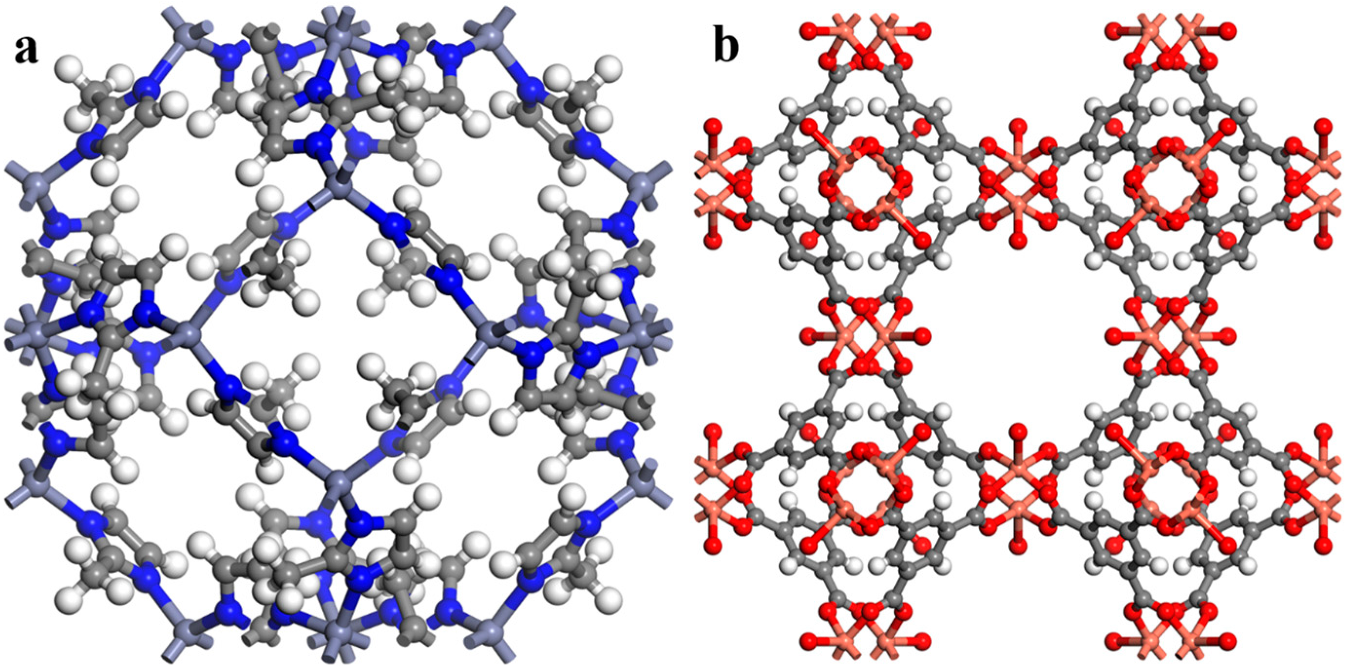
| ZIF-8 | 3 3 1 | 50.8 × 50.8 × 16.9 |
| HKUST-1 | 3 3 1 | 78.9 × 78.9 × 26.3 |
| Porous Solid | Atom | ε (kcal·mol−1) | σ (Å) |
|---|---|---|---|
| ZIF-8 | Zn | 0.124 | 2.462 |
| N | 0.069 | 3.261 | |
| C1 (CNN) | 0.105 | 3.431 | |
| C2 (CNH) | 0.105 | 3.431 | |
| C3 (CHHH) | 0.105 | 3.431 | |
| H2 (-C2) | 0.044 | 2.571 | |
| H3 (-C3) | 0.044 | 2.571 | |
| HKUST-1 | Cu | 0.005 | 3.114 |
| O | 0.060 | 3.118 | |
| C1 (COO) | 0.105 | 3.431 | |
| C2 (CCC) | 0.105 | 3.431 | |
| C3 (CCH) | 0.105 | 3.431 | |
| H | 0.044 | 2.571 |
| Porogen | CSD CODE | Density (g cm−3) | Pore Limiting Diameter (Å) | Largest Cavity Diameter (Å) | Void Fraction | Refs. |
|---|---|---|---|---|---|---|
| ZIF-8 | OFERUN07 | 0.933 | 3.330 | 11.392 | 0.63 | [59,60] |
| HKUST-1 | ADABAK | 1.640 | 3.392 | 3.922 | 0.392 | [60,61] |
| Solvent | Chemical Formula | Shape | Viscosity (mPa s) | Kinetic Diameter (Å) | Quantum Mechanical | Material Studio Size after MD (Å) | ||
|---|---|---|---|---|---|---|---|---|
| QM Diameter (Å) | Length | Height | Depth | |||||
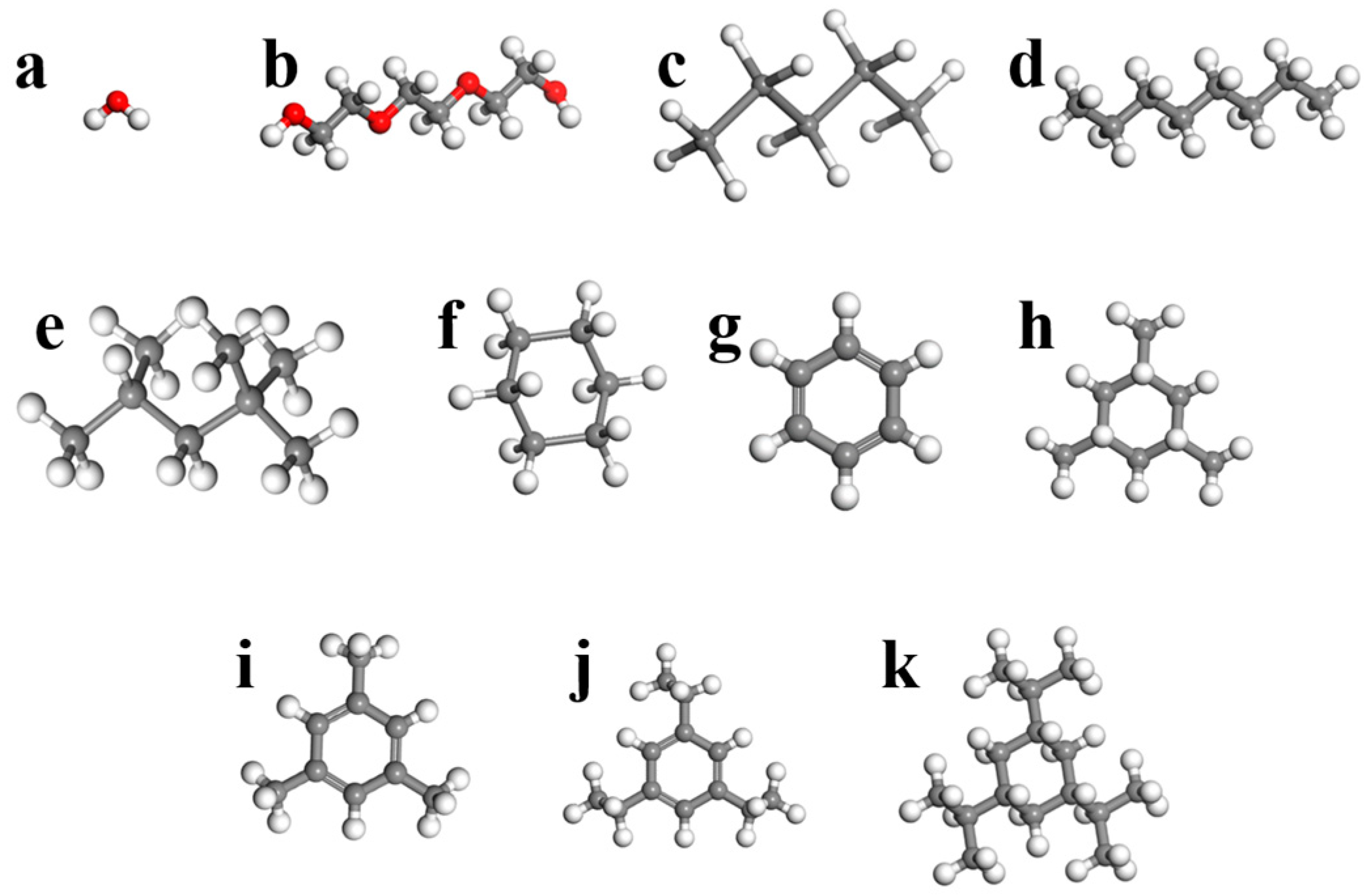
| Water | H2O | Ellipsoidal | - | 2.65 | 3.20 | 3.93 | 3.32 | 3.04 |
| Triethylene glycol | C6H14O4 | Prolate rod cylinder | 47.8 | - | 7.89 | 14.00 | 4.77 | 4.25 |
| n-pentane | C5H12 | Prolate rod cylinder | 0.224 | 4.522 | 6.46 | 9.19 | 4.57 | 4.17 |
| n-octane | C8H18 | Prolate rod cylinder | 0.5624 | 4.537 | 7.76 | 13.09 | 4.80 | 4.17 |
| iso-octane | C8H18 | Rectangular | 0.51 | 6.2 | 7.31 | 8.97 | 6.51 | 6.35 |
| Cyclohexane | C6H12 | Spherical | 0.89 | 6.7 | 6.27 | 6.61 | 6.71 | 5.32 |
| Benzene | C6H6 | Oblate disk cylinder | 0.5279 | 5.85 | 5.99 | 6.75 | 6.72 | 3.40 |
| 1,3,5-trimethylcyclohexane | C9H18 | Triangular | - | - | 7.55 | 6.61 | 6.71 | 5.32 |
| 1,3,5-trimethylbenzene | C9H12 | Triangular | 0.727 | - | 7.61 | 8.38 | 8.33 | 4.07 |
| 1,3,5-triisopropylecyclohexane | C15H30 | Triangular | - | - | 9.41 | 9.12 | 7.81 | 4.58 |
| 1,3,5-triisopropylebenzene | C15H24 | Triangular | - | - | 9.50 | 10.60 | 9.72 | 6.72 |
| Solvent | Simulation Density (g cm−1) | References Density (g cm−3) | Error (%) | Ref. |
|---|---|---|---|---|
| Water | 0.9972 | 0.9982 | 0.1001 | - |
| Triethylene glycol | 1.1267 | 1.1274 | 0.06204 | [63] |
| n-pentane | 0.6238 | 0.626 | 0.3514 | [64] |
| n-octane | 0.698 | 0.703 | 0.7112 | [65] |
| iso-octane | 0.6944 | 0.6919 | 0.3613 | [65] |
| Cyclohexane | 0.7735 | 0.7781 | 0.5911 | [63] |
| Benzene | 0.8732 | 0.8790 | 0.6598 | [65] |
| 1,3,5-trimethylcyclohexane | 0.7172 | 0.7180 | 0.1114 | [63] |
| 1,3,5-trimethylbenzene | 0.8593 | 0.8637 | 0.5094 | [63] |
| 1,3,5-triisopropylcyclohexane | 0.7951 | 0.8000 | 0.6125 | [66] |
| 1,3,5-triisopropylbenzene | 0.8415 | 0.8447 | 0.3788 | [31] |
Disclaimer/Publisher’s Note: The statements, opinions and data contained in all publications are solely those of the individual author(s) and contributor(s) and not of MDPI and/or the editor(s). MDPI and/or the editor(s) disclaim responsibility for any injury to people or property resulting from any ideas, methods, instructions or products referred to in the content. |
© 2024 by the authors. Licensee MDPI, Basel, Switzerland. This article is an open access article distributed under the terms and conditions of the Creative Commons Attribution (CC BY) license (https://creativecommons.org/licenses/by/4.0/).
Share and Cite
Faramarzi, H.; Rahimi, M.; Mahdavi, H.; Niazi, S. Development of a Molecular Dynamics Model to Assess the Possibility of Type II/III Porous Liquid Formation. Processes 2024, 12, 762. https://doi.org/10.3390/pr12040762
Faramarzi H, Rahimi M, Mahdavi H, Niazi S. Development of a Molecular Dynamics Model to Assess the Possibility of Type II/III Porous Liquid Formation. Processes. 2024; 12(4):762. https://doi.org/10.3390/pr12040762
Chicago/Turabian StyleFaramarzi, Hamed, Masoud Rahimi, Hamidreza Mahdavi, and Saber Niazi. 2024. "Development of a Molecular Dynamics Model to Assess the Possibility of Type II/III Porous Liquid Formation" Processes 12, no. 4: 762. https://doi.org/10.3390/pr12040762
APA StyleFaramarzi, H., Rahimi, M., Mahdavi, H., & Niazi, S. (2024). Development of a Molecular Dynamics Model to Assess the Possibility of Type II/III Porous Liquid Formation. Processes, 12(4), 762. https://doi.org/10.3390/pr12040762