
Study on Characteristics of Front Abutment Pressure and Rational Stop-Mining Coal Pillar Width in Large Height Working Face
 ,
,
Abstract
:1. Introduction
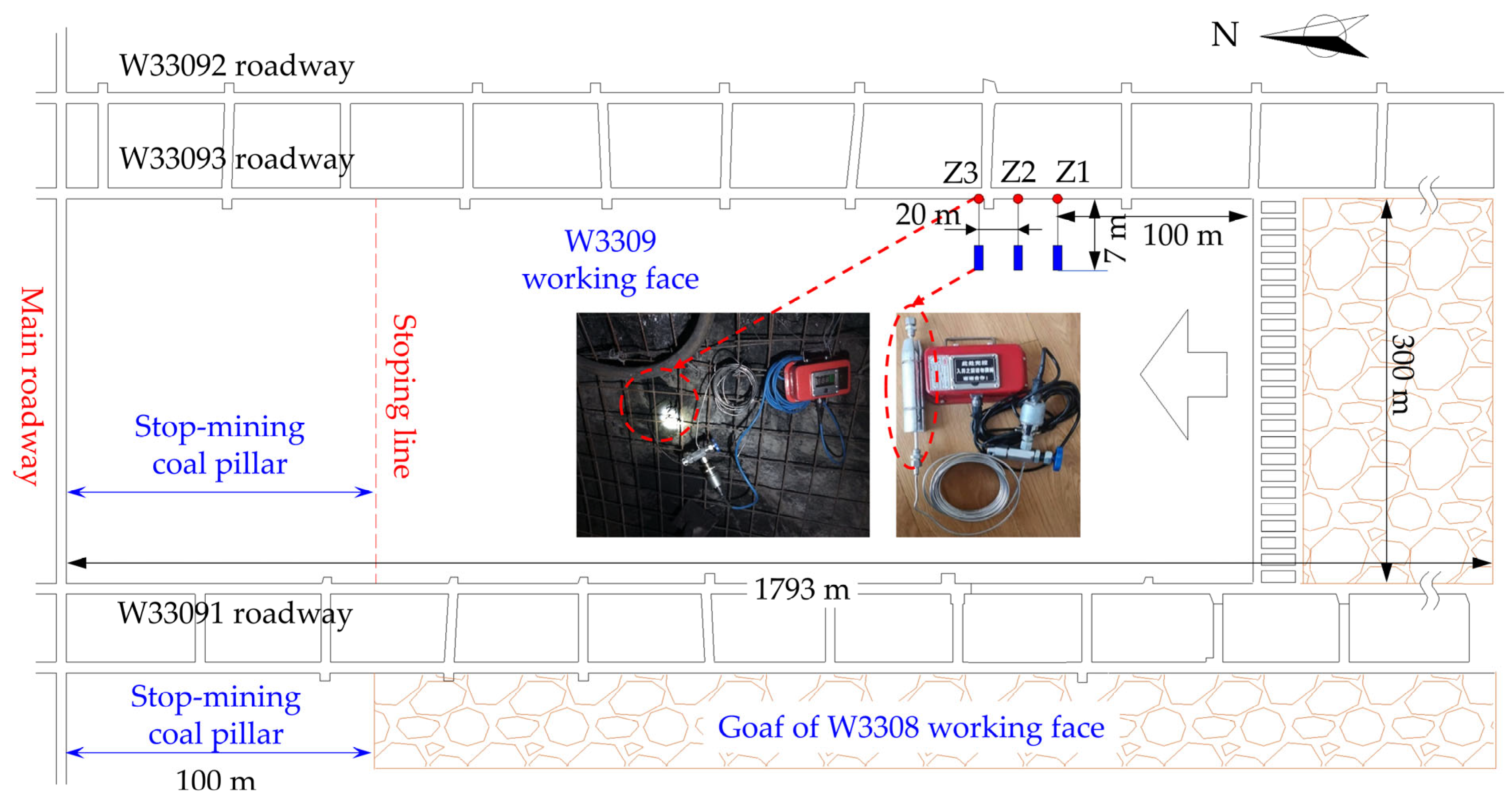
2. Study Area
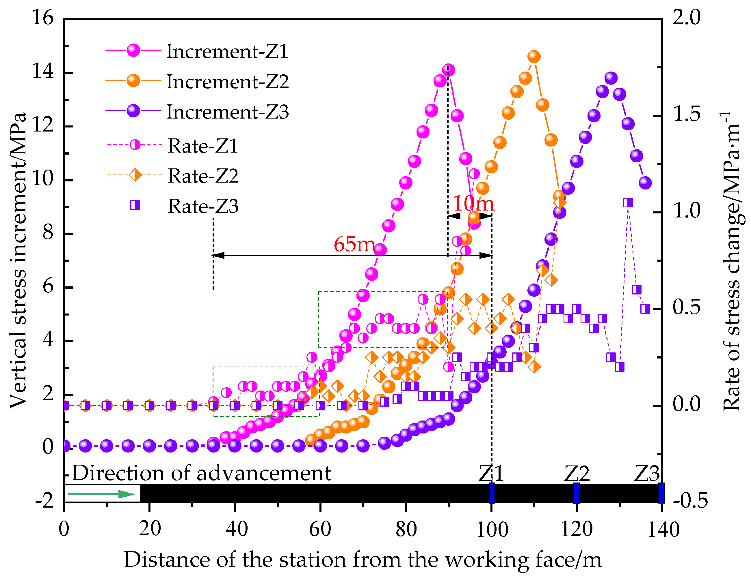
3. Characteristics of FAP in Large Height Working Face
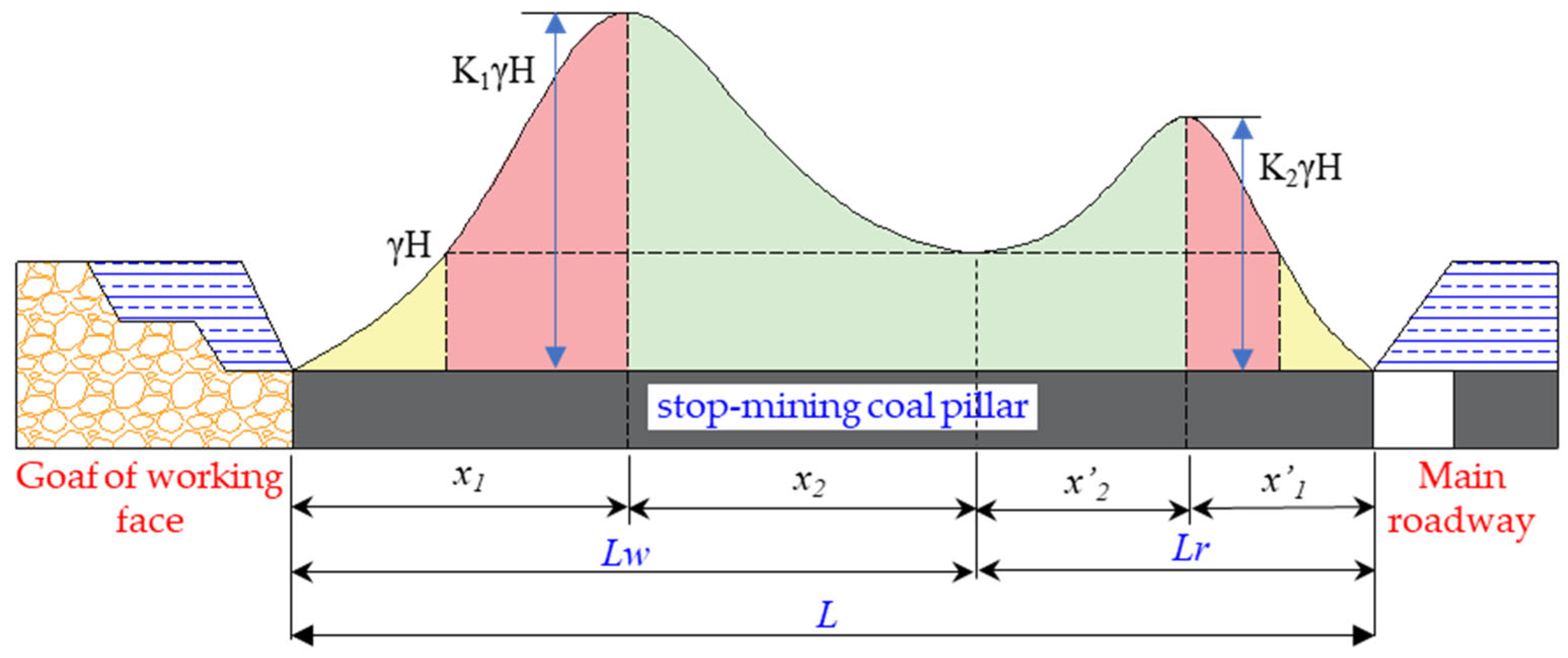
4. Determination of Rational Width of SMCP
4.1. Theoretical Calculation
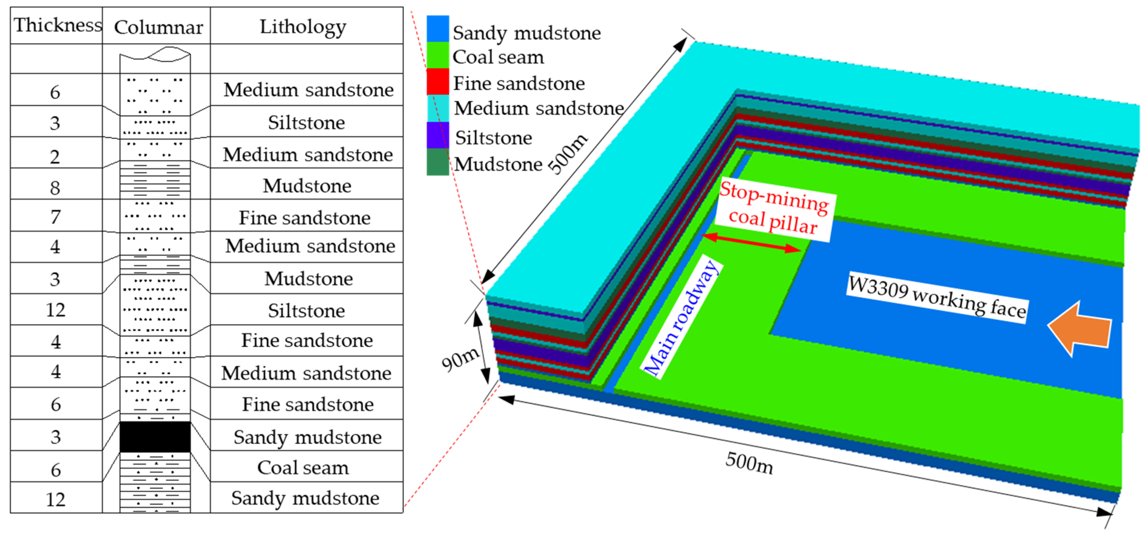
4.2. Numerical Analysis
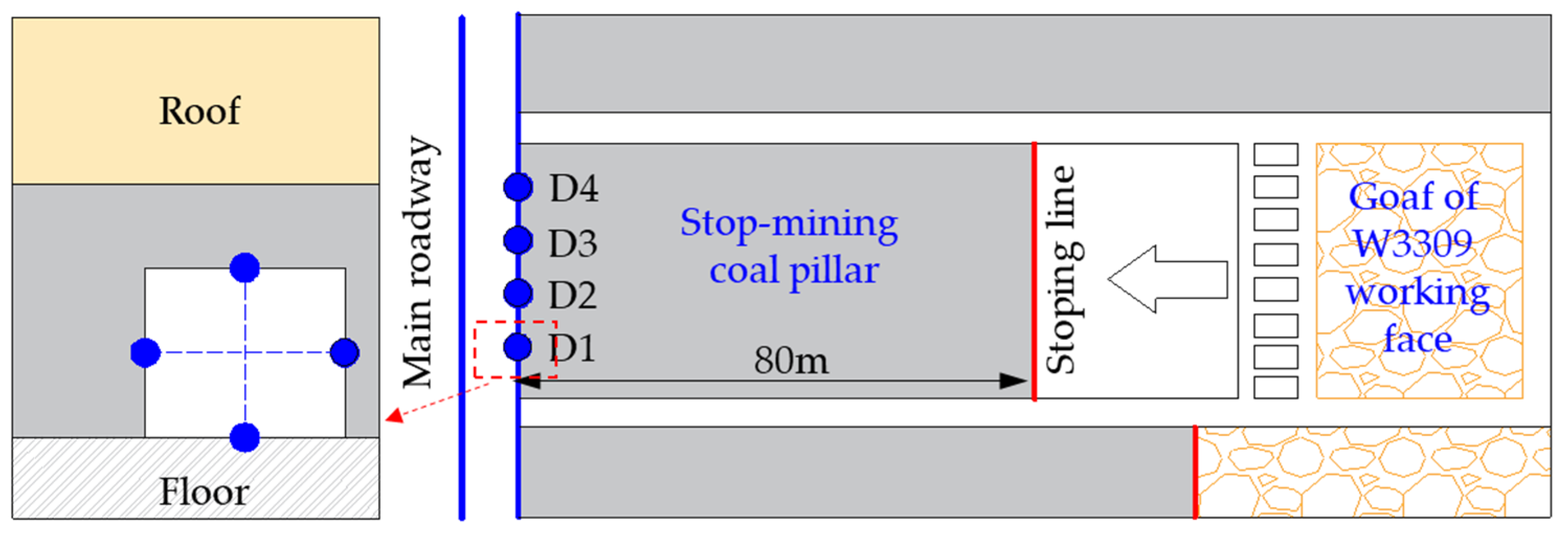
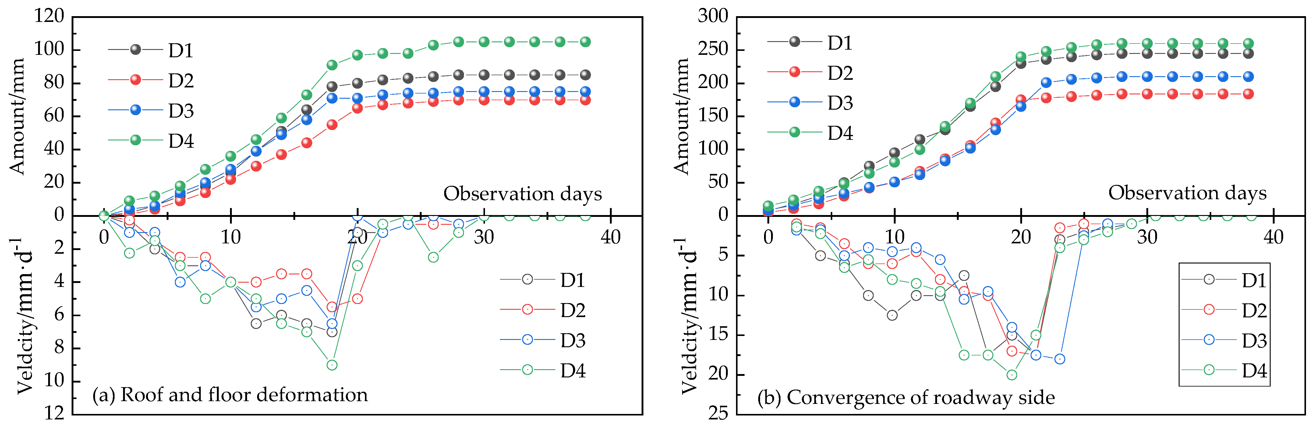
5. Field Application
6. Discussion
7. Conclusions
- (1)
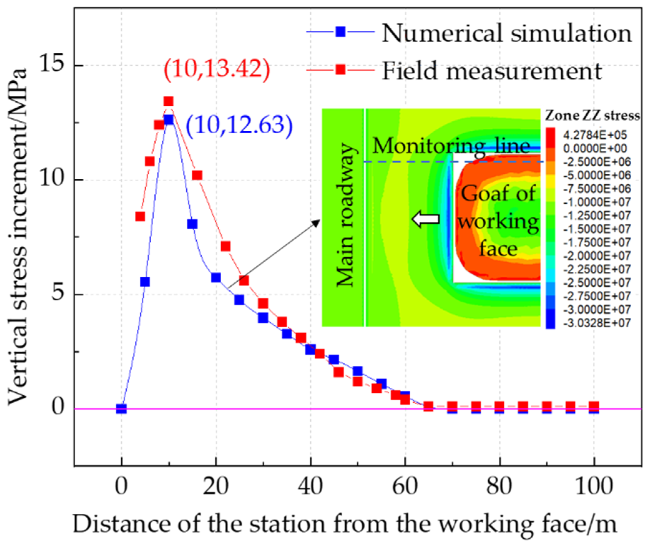
- The characteristics of FAP in a large height working face and its influence factors’ sensitivity are analyzed. The results show that the influence of FAP ranges from 0 to 65 m. Mining height has a significant effect on the FAP, and the significance ranking of the factors’ influence is mining height > working face length > advancing speed.
- (2)
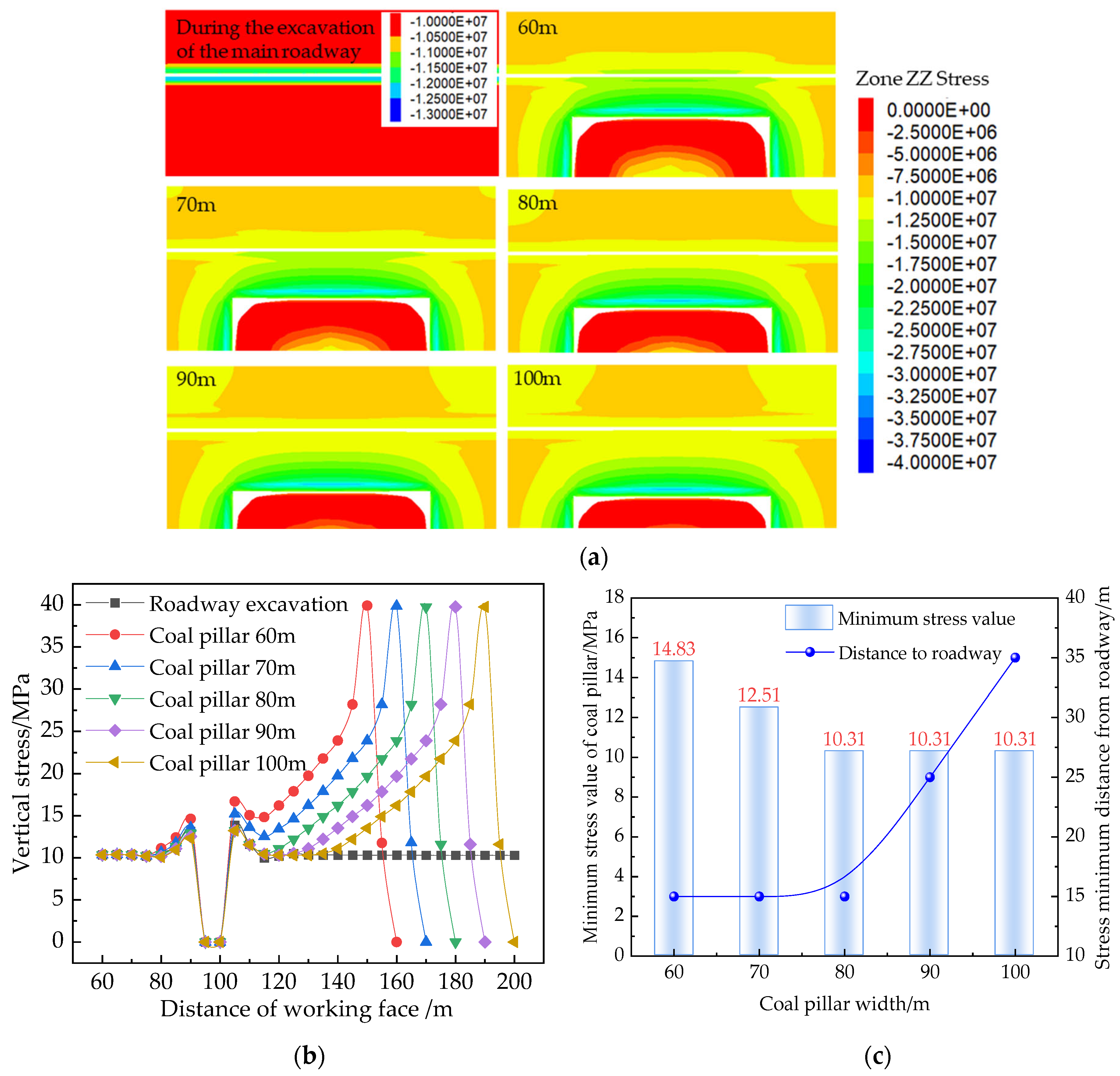
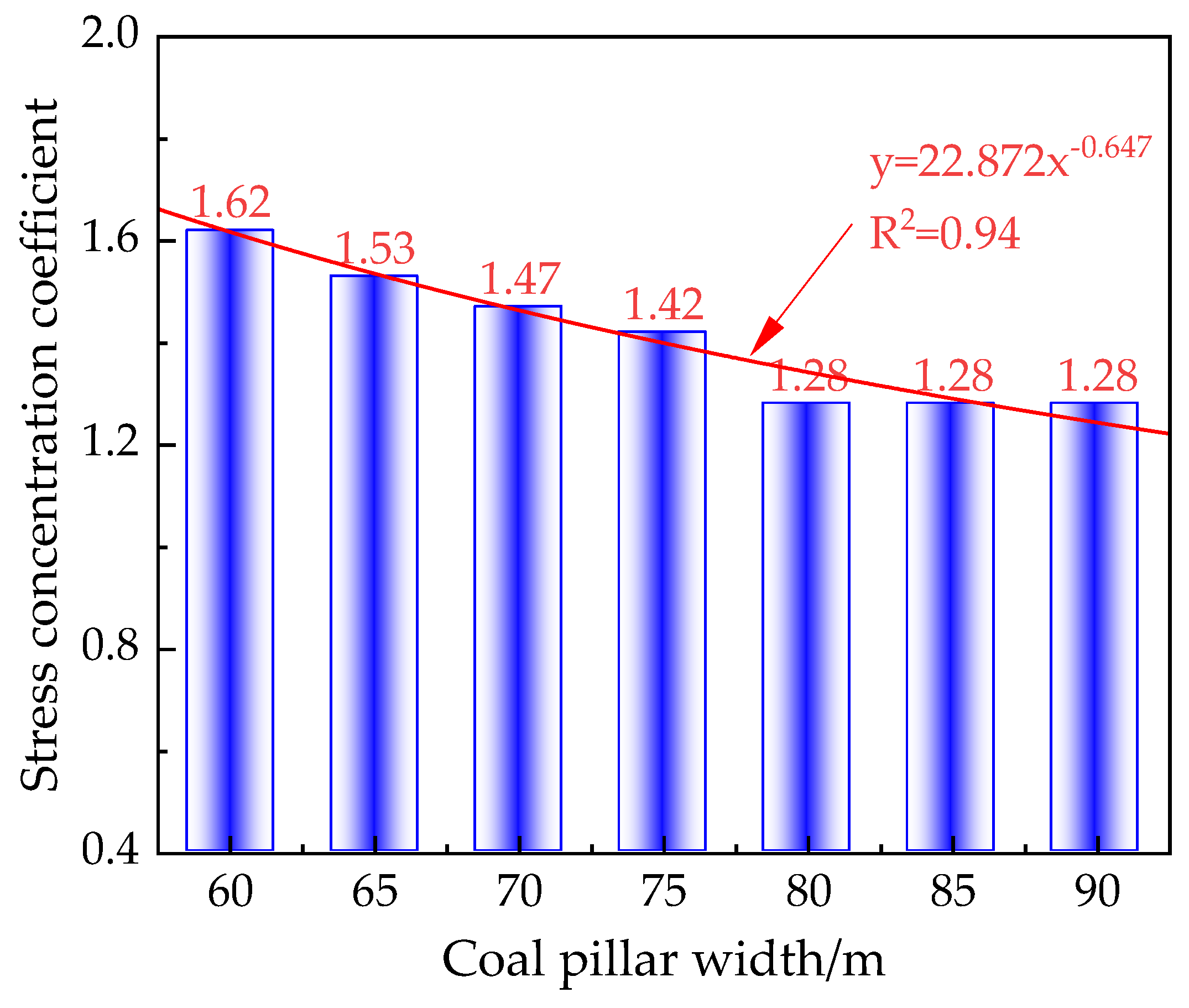
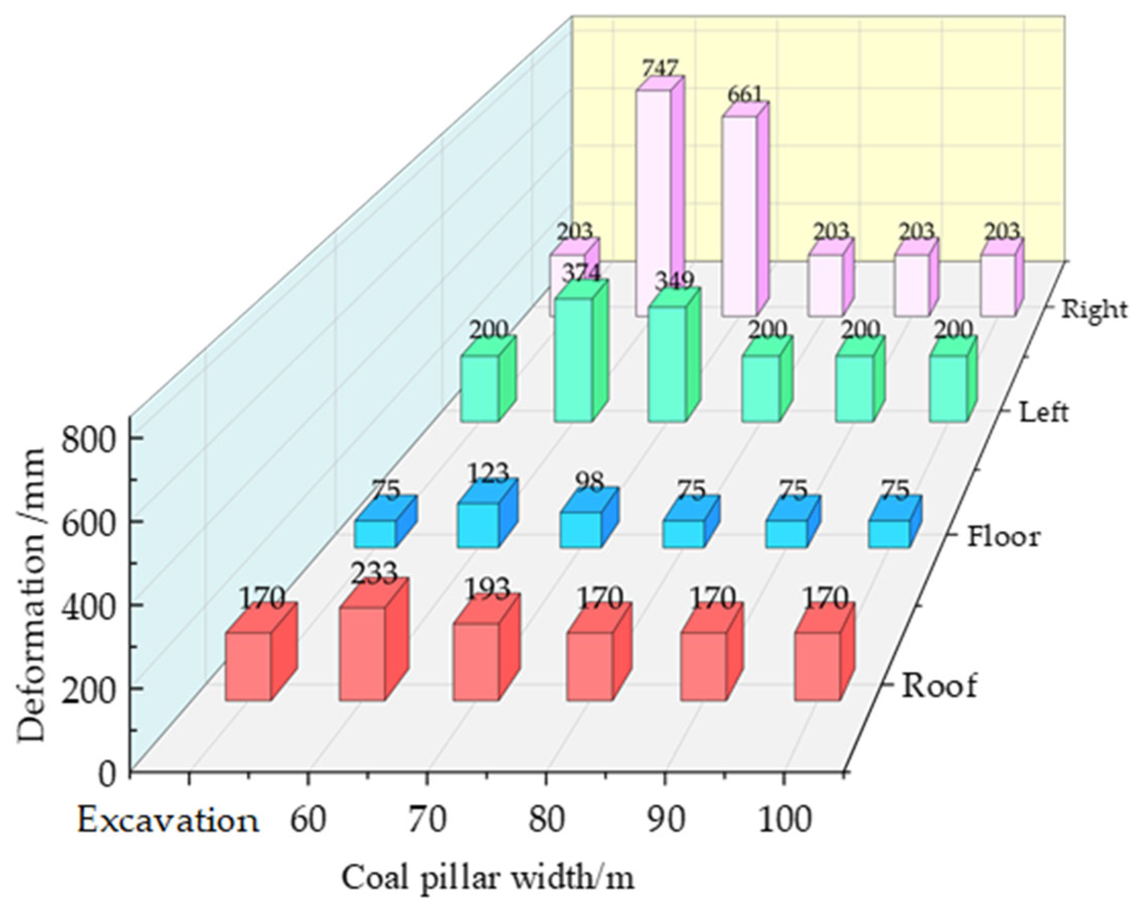
- The method of determining the width of SMCPs by taking the internal stress of the coal pillar, the vertical stress, and the deformation characteristics of the MRSR as the indexes is proposed. The results show that when the SMCP width is 80 m, the main roadway is in a critical state of mining disturbance.
- (3)
- The SMCP width was determined to be 80 m, and its reasonableness was evaluated by industrial tests. On-site application indicates that the maximum value of roof-to-floor convergence of the main roadway is 105 mm, and the maximum value of side-to-side convergence is 260 mm. The overall deformation of the MRSR is small, which means it can effectively maintain the stability of the roadway and meet the needs of safety operation.
Author Contributions
Funding
Data Availability Statement
Conflicts of Interest
References
- Bu, Q.; Tu, M.; Fu, B. Research on the Redistribution Law of Lateral Mining Stress and the Bearing Characteristics of Section Coal Pillar in Extra-Thick Fully Mechanized Top-Coal Caving Mining. Shock Vib. 2021, 2021, 4355977. [Google Scholar] [CrossRef]
- He, X.; He, S.; Cai, Y.; Xu, R.Y.; Yang, K. Investigation on rational width of coal pillar and roadway support in isolated panel of extra-thick coal seam. Front. Earth Sci. 2023, 11, 1125678. [Google Scholar] [CrossRef]
- Zhao, S.; Zuo, J.; Liu, L.; Wu, K. Study on the Retention of Large Mining Height and Small Coal Pillar under Thick and Hard Roof of Bayangaole Coal. Adv. Civ. Eng. 2021, 2021, 8837189. [Google Scholar] [CrossRef]
- He, W.; He, F.; Zhao, Y. Field and simulation study of the rational coal pillar width in extra-thick coal seams. Energy Sci Eng. 2020, 8, 627–646. [Google Scholar] [CrossRef]
- Zhang, C.; Zhao, Y.; Han, P.; Bai, Q. Coal pillar failure analysis and instability evaluation methods: A short review and prospect. Eng. Fail. Anal. 2022, 138, 106344. [Google Scholar] [CrossRef]
- Zhang, J.; Sun, S.; Wang, Z.; Li, J. Research and Application of Prefilled Concrete Wall to Reduce the Size of Stopping Mining Coal Pillar. Geofluids 2022, 2022, 8526755. [Google Scholar] [CrossRef]
- Frith, R.; Reed, G. Limitations and potential design risks when applying empirically derived coal pillar strength equations to real-life mine stability problems. Int. J. Min. Sci. Technol. 2019, 29, 17–25. [Google Scholar] [CrossRef]
- Das, A.J.; Mandal, P.K.; Paul, P.S.; Sinha, R.K. Generalised Analytical Models for the Strength of the Inclined as well as the Flat Coal Pillars using Rock Mass Failure Criterion. Rock Mech. Rock Eng. 2019, 52, 3921–3946. [Google Scholar] [CrossRef]
- Kumar, R.; Mandal, P.K.; Ghosh, N.; Das, A.J.; Banerjee, G. Design of Stable Parallelepiped Coal Pillars Considering Geotechnical Uncertainties. Rock Mech. Rock Eng. 2023, 56, 6581–6602. [Google Scholar] [CrossRef]
- Liu, Y.; Lu, C.; Wang, H.; Guo, Y.; Xiao, Z.; Xia, L.; Wang, C. Moment tensor inversion study on deformation andfailure mechanism of the irregular coal pillar. J. Min. Saf. Eng. 2023, 40, 1201–1209. [Google Scholar] [CrossRef]
- Song, C.; Lu, C.; Zhang, X.; Wang, C.; Xie, H.; Yan, X.; Yang, H. Moment Tensor Inversion and Stress Evolution of Coal Pillar Failure Mechanism. Rock Mech. Rock Eng. 2022, 55, 2371–2383. [Google Scholar] [CrossRef]
- Nie, B.; Zhang, H.; Liu, X.; Li, Y.; Deng, B.; He, H.; Liu, P. Experimental Study on the Mechanical Stability and Mesoscopic Damage Characteristics of Coal Under Different Mining Disturbance Rates. Rock Mech. Rock Eng. 2024, 57, 3841–3861. [Google Scholar] [CrossRef]
- Liu, W.; Cheng, W.; Liu, X.; Zhang, Z.; Yue, Z.; Yang, L.; Shen, A. Effects of Loading Rate and Notch Geometry on Dynamic Fracture Behavior of Rocks Containing Blunt V-Notched Defects. Rock Mech. Rock Eng. 2024, 57, 2501–2521. [Google Scholar] [CrossRef]
- Sinha, S.; Walton, G. Investigation of longwall headgate stress distribution with an emphasis on pillar behavior. Int. J. Rock Mech. Min. Sci. 2019, 121, 104049. [Google Scholar] [CrossRef]
- Klemetti, T.M.; Van Dyke, M.A.; Tulu, I.B.; Tuncay, D. A case study of the stability of a non-typical bleeder entry system at a U.S. longwall mine. Int. J. Min. Sci. Technol. 2020, 30, 25–31. [Google Scholar] [CrossRef] [PubMed]
- Zhang, S.; Wang, X.; Fan, G.; Zhang, D.; Cui, J. Pillar size optimization design of isolated island panel gob-side entry driving in deep inclined coal seam-case study of Pingmei No. 6 coal seam. J. Geophys. Eng. 2018, 15, 816–828. [Google Scholar] [CrossRef]
- Xiang, X.; Yang, X.; Ma, C.; Ren, Q.; Zhang, C.; Fang, P.; Luo, B.; Sun, Y. Determination of Reasonable Stopping Line Position in Weakly Cemented Soft Rock Face under Influence of Fault. Coal Technol. 2022, 41, 29–33. [Google Scholar] [CrossRef]
- Zhai, W.; He, F.; Li, L.; Song, J.; Xu, X.; Lv, K.; Wang, D.; Ma, Q. Study on deflection of principal stress and deformation characteristics of roadway surrounding rock under mining action in close-distance coal seams. Geomat. Nat. Hazards Risk 2023, 14, 2227327. [Google Scholar] [CrossRef]
- Wang, D.; He, F.; Wu, Y.; Xu, X.; Zhang, J.; Lv, K.; Li, L.; Zhai, W.; Song, J. Study on surrounding rock failure mechanism and rational coal pillar width of the gob-side coal roadway under influence of intense dynamic pressure. Energy Sci. Eng. 2023, 11, 1716–1733. [Google Scholar] [CrossRef]
- He, F.; Li, L.; Lv, K.; Qin, B.; Xu, X.; Ma, Q.; Chen, Y. Study on Evolution of Front Abutment Pressure at Working Face in Repeated Mining of Close-Distance Coal Seams. Sustainability 2022, 14, 12399. [Google Scholar] [CrossRef]
- Feng, G.; Wang, G.; Wang, P.; Guo, J.; Yan, Y.; Ren, Y. Study on rational width of the end-mining coal pillar of extra-thickmining panel in permo-carboniferous igneous rock intrusion area. J. Min. Saf. Eng. 2019, 36, 87–94. [Google Scholar] [CrossRef]
- Guo, J.; Feng, G.; Wang, P.; Qi, T.; Zhang, X.; Yan, Y. Roof Strata Behavior and Support Resistance Determination for Ultra-Thick Longwall Top Coal Caving Panel: A Case Study of the Tashan Coal Mine. Energies 2018, 11, 1041. [Google Scholar] [CrossRef]
- Yu, Y.; Bai, J.; Zhang, S.; Guo, Y.; Zhang, L. Disaster mechanism of surrounding rock withdouble wing mining roadway group and its repairand reinforcement system. J. Min. Saf. Eng. 2020, 37, 1133–1141. [Google Scholar] [CrossRef]
- Sun, Y.; Bi, R.; Chang, Q.; Taherdangkoo, R.; Zhang, J.; Sun, J.; Huang, J.; Li, G. Stability Analysis of Roadway Groups under Multi-Mining Disturbances. Appl. Sci. 2021, 11, 7953. [Google Scholar] [CrossRef]
- Yang, S.; Li, G.; Bi, R.; Yao, B.; Feng, R.; Sun, Y. The Stability of Roadway Groups under Rheology Coupling Mining Disturbance. Sustainability 2021, 13, 2300. [Google Scholar] [CrossRef]
- Vu, T.T. Solutions to prevent face spall and roof falling in fully mechanized longwall at underground mines, Vietnam. Min. Miner. Depos. 2022, 16, 127–134. [Google Scholar] [CrossRef]
- Shavarskyi, I.; Falshtynskyi, V.; Dychkovskyi, R.; Akimov, O.; Sala, D.; Buketov, V. Management of the longwall face advance on the stress-strain state of rock mass. Min. Miner. Depos. 2022, 16, 78–85. [Google Scholar] [CrossRef]
- Song, B.; Zhang, S.; Zhang, D.; Fan, G.; Yu, W.; Zhao, Q.; Liang, S. Inorganic Cement Grouting for Reinforcing Triangular Zone of Highly Gassy Coal Face with Large Mining Height. Energies 2018, 11, 2549. [Google Scholar] [CrossRef]
- Zhou, H.; Qu, C.; Huang, J.; Zhang, C.; Hu, M.; Tang, J. Analysis of rational shape of stop line in deep coal seam based on model test. Chin. J. Rock Mech. Eng. 2017, 36, 2373–2382. [Google Scholar] [CrossRef]
- Gong, P.; Chen, Y.; Ma, Z.; Cheng, S. Study on Stress Relief of Hard Roof Based on Presplitting and Deep Hole Blasting. Adv. Civ. Eng. 2020, 2020, 8842818. [Google Scholar] [CrossRef]
- Liu, C.; Wang, F.; Zhang, Z.; Zhu, D.; Hao, W.; Tang, T.; Zhang, X.; Zhu, C. Surrounding Rock Deformation Mechanism and Control Technology for the Roadway in the Fault-Disturbed Zone under Special-Shaped Coal Pillars. Processes 2023, 11, 3264. [Google Scholar] [CrossRef]
- Ma, Q.; Zhang, Y.; Li, Z.; Zheng, Y.; Song, G.; Hu, L. The Optimized Roadway Layouts and Surrounding Rock Control Technology of the Fully Mechanized Mining Surface with Large Mining Heights in High-Gas Mines. Processes 2022, 10, 2657. [Google Scholar] [CrossRef]
- Ren, W.T.; Chen, J.T.; Liu, W.Z. Study on Mine Zoning Based on lmpact Index of Advanced Abutment Pressure. Min. Res. Dev. 2019, 39, 71–75. [Google Scholar] [CrossRef]
- Jin, Z.P.; Qin, T.; Zhang, J.W. Analysis of abutment pressure distribution characteristics and influencing factors of deep mining height face. Coal Sci. Technol. 2018, 46, 97–99+134. [Google Scholar] [CrossRef]
- Xie, S.; Wu, Y.; Ma, X.; Chen, D.; Guo, F.; Jiang, Z.; Li, H.; Zou, H.; Liu, R.; Zhang, X. Reasonable stopping method and retracement channel support at fully mechanized top coal caving working face of 15 m extra-thick coal seam: A case study. Energy Sci. Eng. 2022, 10, 4336–4357. [Google Scholar] [CrossRef]
- Zhang, X.; Li, X.; Tong, Z.; Gao, Y.; Zhao, X. Enhancing recovery efficiency during the final mining phase offully mechanized caving mining under thick-coal hard-roofconditions: Countermeasures and strategies. J. Min. Saf. Eng. 2024, 41, 295–304. [Google Scholar] [CrossRef]
- Ren, X.; Hao, B.; Wang, H.; Zhao, J.; Zhang, J.; Zhang, C. Roadway Protection by Roof-Cutting in the Support Removing Channel of the Long-Wall Mining Face. Shock Vib. 2022, 2022, 8116399. [Google Scholar] [CrossRef]
- Malashkevych, D.; Petlovanyi, M.; Sai, K.; Zubko, S. Research into the coal quality with a new selective mining technology of the waste rock accumulation in the mined-out area. Min. Miner. Depos. 2022, 16, 103–114. [Google Scholar] [CrossRef]
- Smoli’nski, A.; Malashkevych, D.; Petlovanyi, M.; Rysbekov, K.; Lozynskyi, V.; Sai, K. Research into Impact of Leaving Waste Rocks in the Mined-Out Space on the Geomechanical State of the Rock Mass Surrounding the Longwall Face. Energies 2022, 15, 9522. [Google Scholar] [CrossRef]

| Lithology | Friction (°) | Cohesion (MPa) | Bulk (GPa) | Shear (GPa) | Tensile (MPa) | Density (kg/m3) |
|---|---|---|---|---|---|---|
| Sandy mudstone | 42.00 | 5.75 | 2.56 | 2.43 | 0.86 | 2777 |
| Coal seam | 30.00 | 2.68 | 6.27 | 2.41 | 3.54 | 1418 |
| Fine sandstone | 40.00 | 4.93 | 2.57 | 1.54 | 1.12 | 2510 |
| Medium sandstone | 28.53 | 6.42 | 8.13 | 4.64 | 3.21 | 2673 |
| Siltstone | 28.10 | 2.10 | 2.57 | 1.54 | 1.01 | 2510 |
| Mudstone | 26.00 | 13.35 | 8.77 | 5.77 | 8.24 | 2635 |
| No. | Factor | Results | ||||
|---|---|---|---|---|---|---|
| M/m | L/m | V/m·d−1 | Empty Column | σzz/MPa | X/m | |
| 1 | 2 | 200 | 4 | 1 | 32.40 | 50 |
| 2 | 2 | 250 | 7 | 4 | 32.50 | 51 |
| 3 | 2 | 300 | 10 | 2 | 32.24 | 53 |
| 4 | 2 | 350 | 13 | 3 | 32.45 | 55 |
| 5 | 4 | 200 | 7 | 3 | 36.37 | 55 |
| 6 | 4 | 250 | 4 | 2 | 36.64 | 56 |
| 7 | 4 | 300 | 13 | 4 | 36.18 | 57 |
| 8 | 4 | 350 | 10 | 1 | 36.94 | 60 |
| 9 | 6 | 200 | 10 | 4 | 39.45 | 62 |
| 10 | 6 | 250 | 13 | 1 | 39.40 | 61 |
| 11 | 6 | 300 | 4 | 3 | 40.35 | 65 |
| 12 | 6 | 350 | 7 | 2 | 40.53 | 67 |
| 13 | 8 | 200 | 13 | 2 | 41.62 | 72 |
| 14 | 8 | 250 | 10 | 3 | 41.59 | 71 |
| 15 | 8 | 300 | 7 | 1 | 41.57 | 70 |
| 16 | 8 | 350 | 4 | 4 | 41.48 | 68 |
| σzz/MPa | X/m | |||||
|---|---|---|---|---|---|---|
| M/m | L/m | V/m·d−1 | M/m | L/m | V/m·d−1 | |
| k1 | 32.40 | 37.46 | 37.72 | 52.25 | 59.75 | 59.75 |
| k2 | 36.53 | 37.53 | 37.74 | 57.00 | 59.75 | 60.75 |
| k3 | 39.93 | 37.59 | 37.76 | 63.75 | 61.25 | 61.50 |
| k4 | 41.57 | 37.85 | 37.41 | 70.25 | 62.50 | 61.25 |
| Rj | 9.17 | 0.39 | 0.33 | 18.00 | 2.75 | 1.75 |
| Source of Variance | Squared Sum of Variance | DoF | Squared Sum of Average Variance | F | Significance | |
|---|---|---|---|---|---|---|
| σzz /MPa | M | 197.469 | 3 | 65.823 | 497.567 | ** |
| L | 0.347 | 3 | 0.116 | 0.874 | ||
| v | 0.284 | 3 | 0.095 | 0.717 | ||
| error | 0.794 | 6 | 0.132 | |||
| X/m | M | 742.188 | 3 | 247.396 | 46.569 | ** |
| L | 21.188 | 3 | 7.063 | 1.329 | ||
| v | 7.187 | 3 | 2.396 | 0.451 | ||
| error | 31.875 | 6 | 5.313 |
Disclaimer/Publisher’s Note: The statements, opinions and data contained in all publications are solely those of the individual author(s) and contributor(s) and not of MDPI and/or the editor(s). MDPI and/or the editor(s) disclaim responsibility for any injury to people or property resulting from any ideas, methods, instructions or products referred to in the content. |
© 2024 by the authors. Licensee MDPI, Basel, Switzerland. This article is an open access article distributed under the terms and conditions of the Creative Commons Attribution (CC BY) license (https://creativecommons.org/licenses/by/4.0/).
Share and Cite
Yu, W.; Fan, G.; Zhang, D.; Guo, W.; Zhang, W.; Zhang, S.; Fan, Z. Study on Characteristics of Front Abutment Pressure and Rational Stop-Mining Coal Pillar Width in Large Height Working Face. Processes 2024, 12, 1170. https://doi.org/10.3390/pr12061170
Yu W, Fan G, Zhang D, Guo W, Zhang W, Zhang S, Fan Z. Study on Characteristics of Front Abutment Pressure and Rational Stop-Mining Coal Pillar Width in Large Height Working Face. Processes. 2024; 12(6):1170. https://doi.org/10.3390/pr12061170
Chicago/Turabian StyleYu, Wei, Gangwei Fan, Dongsheng Zhang, Wenhao Guo, Wenhui Zhang, Shizhong Zhang, and Zhanglei Fan. 2024. "Study on Characteristics of Front Abutment Pressure and Rational Stop-Mining Coal Pillar Width in Large Height Working Face" Processes 12, no. 6: 1170. https://doi.org/10.3390/pr12061170