Article

Study of Retention of Drilling Fluid Layer on Annulus Wall during Cementing

1
State Key Laboratory of Offshore Natural Gas Hydrates, Beijing 100028, China
2
CNOOC Research Institute Co., Ltd., Beijing 100028, China
3
Key Laboratory of Unconventional Oil & Gas Development, Ministry of Education, Colloge of Petroleum Engineering, China University of Petroleum (East China), Qingdao 266580, China
*
Authors to whom correspondence should be addressed.
Processes 2024, 12(6), 1176; https://doi.org/10.3390/pr12061176
Submission received: 16 April 2024 / Revised: 28 May 2024 / Accepted: 4 June 2024 / Published: 7 June 2024
(This article belongs to the Section Energy Systems)

Abstract

:
To guarantee that the cement sheath has a sealing effect, it is best to replace the drilling fluid entirely and fill the annulus with cement slurry throughout the cementing process. A significant driving power and high stability at the interface between the cement slurry and drilling fluid are often necessary for achieving a high displacement efficiency. It is important that a comprehensive theoretical characterization is established on the thickness and location of drilling fluid retention and the conditions to prevent the formation of drilling fluid retention. In this study, firstly, the characteristics of annulus fluid shear stress distribution are analyzed by establishing the differential equation of shear stress distribution. Subsequently, the calculation model of the drilling fluid retention layer’s thickness is constructed. Subsequently, the impact of cement slurry and drilling fluid properties, eccentricity of the casing, and additional variables on the annular wall’s drilling fluid retention thickness are scrutinized. The quantitative conditions for preventing drilling fluid retention are also analyzed (i.e., Equation (23)). Based on the newly developed model, a case study is conducted to show the significance of the new model. This offers a theoretical foundation for enhancing cement injection displacement efficiency and cementing performance optimization.

1. Introduction

Cementing of oil and gas wells is the last working procedure in the drilling process, while it is the key process to connect drilling and oil production [1,2]. In order to support the casing and seal the permeable formation layer outside the casing, cement slurry is injected into the annulus between the formation and the casing during the cementing process [3]. The quality of cementing is not only closely related to drilling quality before cementing, but also has a great impact on subsequent well testing and oil production [4], which will exert a significant effect on the service life of the oil well. When the drilling fluid is replaced by cement slurry in an oil well, it is ideal that the drilling fluid is completely replaced and the annulus is filled with cement slurry, which is the basic premise to ensure the sealing effect of cement sheath [5,6].
During cement displacement, the instability of the displacement interface can lead to the drilling fluid being trapped in the annulus [7]. In addition, due to the insufficient driving force for displacing drilling fluid, the cement slurry protrudes along the center of annular space, forming a drilling fluid retention layer on the well wall and casing wall [8]. The displacement process starts from the center of annulus gap and gradually extends to both sides [9]. When the displacement interface develops to the annular wall, the displacement efficiency reaches its maximum. However, drilling fluid is generally a fluid with yield characteristics [10]. Prior to reaching the wall, if a stable displacement interface is created through the interaction of cement slurry displacement force and resistance, the drilling fluid between this interface and the annulus wall will be trapped [11], resulting in the formation of a layer that retains drilling fluid. The retained drilling fluid affects the performance of cement slurry, and even leads to micro fractures at the two interfaces, providing a favorable channel for fluid channeling [12].
There are established guidelines for use in fluid displacement processes, but there is room for improvement as there are still issues causing ineffective displacement and cement contamination. It is important to pinpoint the technology gaps that need to be addressed in order to enhance cement placement procedures [13]. Various studies have examined how the rheological properties of the fluids being displaced and the displacing fluids impact each other [14,15]. The studies suggest that a high viscosity ratio between the displacing fluid and the displaced fluid improves the displacement process. Additionally, it is important for the mud’s gel strength to be low so that the gelled mud can break down and be removed from the narrow side of the annulus. Furthermore, the yield stress of the mud and spacer should be kept low to avoid getting stuck in the narrow side. The industry recognizes that for effective displacement, the displacing fluid should be denser than the displaced fluid. It was noted that the buoyant force resulting from the density contrast between drilling fluid and cement has a lesser impact on mud displacement than anticipated. This finding was also observed by Haut et al. [16], who discovered that increasing the density difference did not enhance displacement efficiency due to the immobility of the drilling fluid. Conversely, some studies have suggested that using a displacing fluid with higher density than the displaced fluid can improve the cementing process and displacement efficiency. For instance, Kroken et al. [17] demonstrated that a greater density contrast between the displacing and displaced fluids in inclined wells and low flow rates can enhance the buoyancy of the displaced fluid, facilitating a vertical flow of the heavier fluid from the wider annular side at the top to the narrower side at the bottom, thereby increasing displacement efficiency. Theoretical research could be further enhanced to offer insights into potential challenges associated with optimizing the design of fluids prior to cementing operations [18,19]. An ideal model should be comprehensive, enabling consideration of all relevant factors, accurate prediction, and efficient computation. While analytical models, based on specific assumptions and simplifications, are computationally efficient, they may not capture the complexities of flow dynamics in intricate scenarios. Conversely, numerical models, while providing detailed solutions, often entail high computational expenses. For example, experimental setups may not replicate annular gap ratios observed in field conditions. Consequently, analytical and semi-analytical approaches are increasingly preferred due to the prolonged computational time required by three-dimensional numerical methods for calculating displacements at actual scales. Reducing and eliminating the retained layer of drilling fluid on the annulus wall can prevent the formation of micro fractures between the cement sheath and the primary and secondary interfaces of the annulus, and effectively improve the cementing quality [20]. At present, there is a lack of systematic and quantitative research on the thickness and location of drilling fluid retention and the conditions to prevent the formation of drilling fluid retention, though there are a number of papers on modeling the displacement efficiency of cementing [10,11,12].
In order to improve the cementing displacement efficiency and provide a theoretical basis for optimizing the cementing performance, the conditions for drilling fluid retention are studied based on laminar flow displacement in this study. The calculation model for the thickness of the drilling fluid retention layer is established, and the thickness of the drilling fluid retention layer is calculated and analyzed. Additionally, the thickness of the drilling fluid retention layer in eccentric annulus is analyzed. In addition, the quantitative conditions for preventing drilling fluid retention is analyzed.

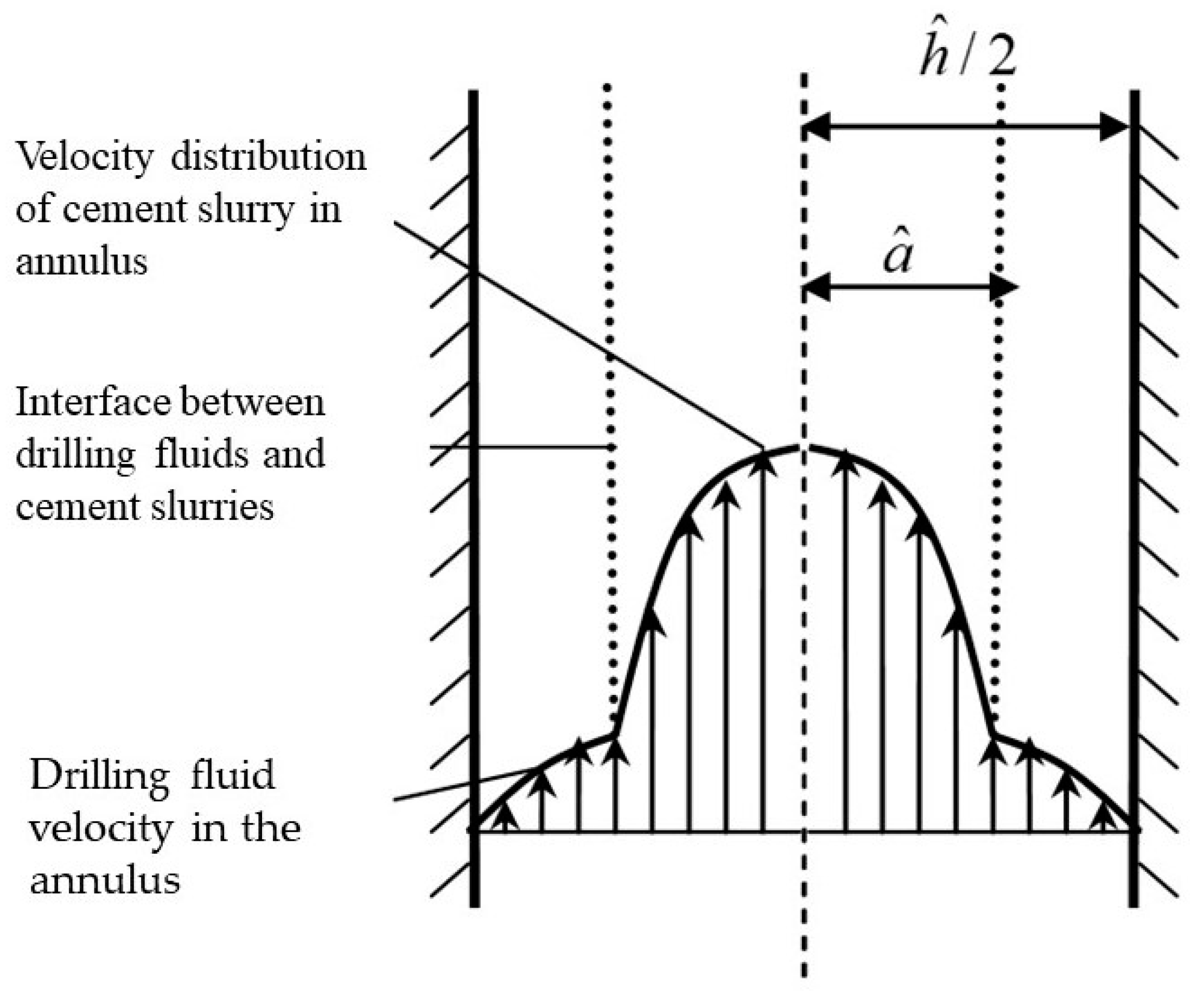
2. Assumption and Description of Calculation Model

The focus of this study is the retention layer of drilling fluid on the annulus wall. To facilitate the research, the following assumptions have been established:
(1)
Take the wellbore annulus, whose length is one casing column, as the object, and regard the entire annulus as consisting of (countless) two flat plates with variable width;
(2)
The flow pattern of cement displacement process is a laminar flow, and the flow rate of cement slurry displacement is constant;
(3)
Both cement slurry and drilling fluid satisfy the Hershel–Bulkley rheological model;
(4)
During cement replacement, the mixing of cement slurry and drilling fluid at the interface is neglected; also, the physical and chemical reactions between cement slurry and drilling fluid at the interface are not considered;
(5)
The shear stress acting on drilling fluid is mainly generated by the axial flow of cement slurry; thus, the circumferential velocity gradient is neglected;
(6)
The influence of mud cake is not considered.
The assumptions are mainly used to simplify the processing conditions and facilitate the establishment of the model. The fundamental assumptions are based on the properties of the drilling fluid retention layer present on the annulus wall.

3. Analysis of Shear Stress Distribution Characteristics of Annulus Fluid

3.1. Differential Equation of Shear Stress Distribution of Annulus Fluid

Based on the geometric characteristics of the wellbore annulus, the wellbore annulus is considered as a series of plates with different widths distributed along the circumference, and the annulus area within the circumference angle θ, θ + is taken as the research object, as shown in Figure 1.
The axial fluid motion equation is dimensionless and processed by considering the non-Newtonian fluid flow properties of drilling fluid and cement slurry within the wellbore annulus [6,21]:
p ξ + y τ ξ y , k ρ k cos β S t = 0
where S t satisfies
S t = τ ^ ρ ^ g ^ r ^ a δ
where k = 1 ,   o r   2 , 1 denotes cement slurry, and 2 represents drilling fluid.
Typically, the density of cement slurry exceeds that of drilling fluid; therefore,
ρ ^ = max k [ ρ ^ k ] = ρ ^ 1
As such, the dimensionless fluid density is provided as follows:
ρ 1 = ρ ^ 1 ρ ^ = 1 ,   ρ 2 = ρ ^ 2 ρ ^
When k = 1 , the cement slurry motion equation (i.e., Equation (1)) is simplified to be
y τ ξ y , 1 = f
By contrast, when k = 2 , the drilling fluid motion Equation (1) is simplified to be
y τ ξ y , 2 = b f
For Equations (5) and (6), f = 1 F p ξ , b = 1 ρ 2 F , F = S t cos β , where p ξ < 0 , and generally f b > 0 .

3.2. Definite Solution Conditions and Dimensionless Treatment of Rheological Model

The basic conditions that cement replacement needs to meet in the annulus consists of a no-slip condition on the wall, symmetry condition, and a stress coupling condition [22], as shown in Figure 2.
The no-slip condition on the wall is
w ( H , ξ ) = 0 ,   w ( H , ξ ) = 0
The symmetry condition is
τ ξ y ( 0 , ξ ) = 0
and the stress coupling condition is
τ ξ y , 1 ( Y i , ξ ) = τ ξ y , 2 ( Y i , ξ )
where w ( y ) refers to the dimensionless velocity of the fluid; H is half of the dimensionless annular-clearance width at a certain circumferential angle, where H = 1 + e cos ( π φ ) ; and Y i denotes the contact surface between cement slurry and drilling fluid, where 0 < Y i H .
Assume that the properties of cement slurry and drilling fluid satisfy the Hershel–Bulkley model, then the rheological model is dimensionless and processed as [6]:
γ & = 0   τ k τ k , Y τ k = τ k , Y + κ k · γ & n k τ k > τ k , Y
In Equation (10), the shear velocity gradient (i.e., γ · ) is expressed as the following equation:
γ & = d w d y                             ( d w d y > 0 ) d w d y                     ( d w d y < 0 )

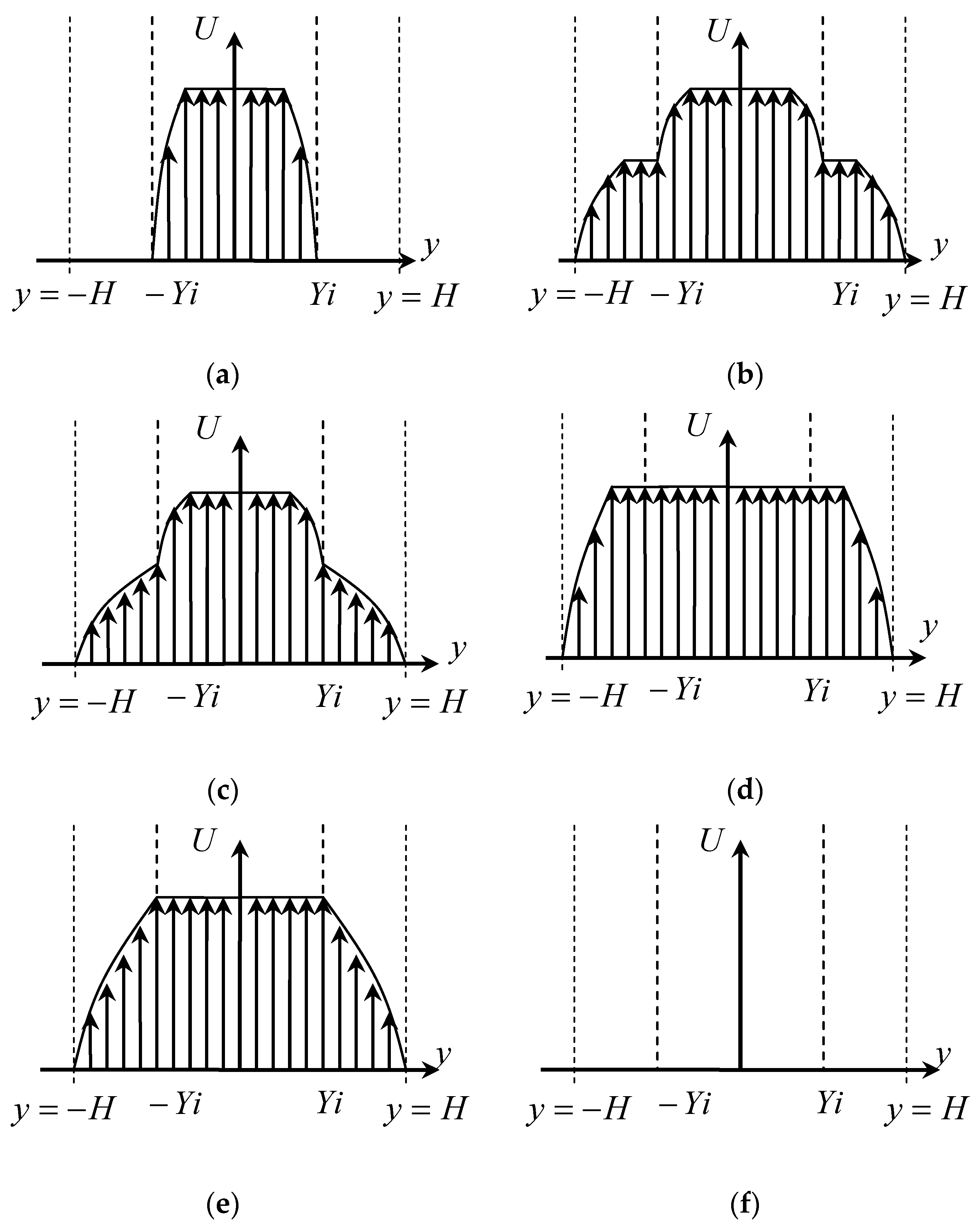
3.3. Analysis on the Distribution Characteristics of Annular Fluid Shear Stress

Combined with the definite solution conditions (i.e., Equations (7)–(9)), the distribution characteristics of shear stress are examined and it is expressed below:
τ 1 = f y   y [ 0 , Y i ]
τ 2 = b Y i + ( b f ) y   y ( H , Y i ]
where τ 1 is yield stress and τ 2 is shear stress of cementing slurry or drilling fluid. Subscript 1 refers to cement slurry and subscript 2 represents drilling fluid. The development of the cement displacement profile under different conditions is acquired, as shown in Figure 3a–f. τ B is the shear stress of the fluid at the wall of two flat plates, and τ Y i is the shear stress of the fluid at the contact surface Y i .
Based on the analysis of Figure 3, when the yield stress of drilling fluid is greater than the yield stress of cement slurry, and the shear stress at the wall is smaller than the yield stress of drilling fluid, that is, τ 1 , Y < τ 2 , Y and τ 2 , Y τ B are met, a certain thickness of drilling fluid retention layer will be formed on the annulus wall, as shown in Figure 3a. The thickness of the drilling fluid retention layer h s t a meets h s t a = H Y i .
( a )   τ 1 , Y < τ Y i     τ 2 , Y τ B   ( b )   τ 1 , Y < τ Y i     τ Y i < τ 2 , Y < τ B   ( c )   τ 1 , Y < τ Y i     τ 2 , Y < τ Y i ( d )   τ 1 , Y τ Y i     τ Y i < τ 2 , Y < τ B   ( e )   τ 1 , Y τ Y i     τ 2 , Y < τ Y i   ( f )   τ 1 , Y τ Y i     τ 2 , Y τ B

4. Calculation Model of Drilling-Fluid-Retention-Layer Thickness

When the cement slurry is injected with a constant rate of w ^ , the corresponding displacement is Q ^ = 2 H ^ B ^ w ^ ; meanwhile, displacement rate w ^ ( y ^ ) and Q ^ meet the following equation:
Q ^ = 2 B ^ H ^ 0 w ^ ( y ^ ) d y ^
In addition, w ^ ( y ^ ) and w ^ satisfy the equation w ^ ( y ^ ) = w ( y ) w ^ ; thus, Equation (14) is simplified as
H 0 w ( y ) d y = H
The region [ H , 0 ] is investigated to determine the fluid velocity distribution between the two plates. Combining the rheological equation (i.e., Equation (10)), fluid shear stress distribution equation (i.e., Equation (12)), and the condition Equations (7) and (8) for cement slurry, the expression of fluid velocity distribution can be derived as follows:
w ( y ) = { κ 1 ( m 1 + 1 ) f [ ( f κ 1 y τ 1 , Y κ 1 ) m 1 + 1 ( f κ 1 Y i τ 1 , Y κ 1 ) m 1 + 1 ]         y [ Y i , y D ] κ 1 ( m 1 + 1 ) f ( f κ 1 Y i τ 1 , Y κ 1 ) m 1 + 1                                                                                               y [ y D , 0 ]
where m 1 is the reciprocal of cement slurry liquidity index, m 1 = 1 / n 1 ; [ y D , 0 ] refers to the range of cement slurry flow core in the area between two flat plates in the annulus, where y D = τ 1 , Y / f . Therefore, the integral expression of Equation (15) can be composed of the following two parts:
Y i 0 w ( y ) d y = Y i Y D w ( y ) d y + Y D 0 w ( y ) d y
Based on the expression for cement slurry velocity distribution, i.e., Equation (16), Equation (17) can be deduced to be
Y i 0 w ( y ) d y = κ 1 ( m 1 + 1 ) f ( f κ 1 Y i τ 1 , Y κ 1 ) m 1 + 1 [ m 1 + 1 m 1 + 2 Y i + τ 1 , Y ( m 1 + 2 ) f ]
when the drilling fluid at the annulus wall cannot be replaced, τ 1 , Y < τ 2 , Y , τ 2 , Y τ B . Combining Equation (13) for fluid shear stress between the two plates yields f H + b H b Y i τ 2 , Y . Thus, the critical condition for drilling fluid retention on the wall is acquired to be
f H + b H b Y i = τ 2 , Y

5. Calculation and Analysis of Thickness of Drilling Fluid Retention Layer

Based on the actual situation of cement displacement (data reference: tail pipe cementing data from Tahe Oilfield in Xinjiang, China), its well depth is generally greater than 6000~6500 m. The drilling fluid is a poly-sulfonate drilling fluid, and its density is 1.20~1.30 g/cm3. The guide slurry of cement slurry is fly ash low-density cement slurry, and its density is 1.50~1.60 g/cm3. The tail slurry of cement slurry is conventional-density cement slurry, and its density is 1.88~1.90 g/cm3. The designed parameters are listed below: trip in a 6 5/8 inch casing in a 8 1/2 inch wellbore, and the displacement of cement slurry is 30 m3/h. The specified characteristics of cement slurry and drilling fluid properties are presented in Table 1.
After the dimensionless processing of the parameters of wellbore and fluid performance mentioned above, we yielded the following: τ 1 , Y = 0.15 , κ 1 = 0.85 , n 1 = 1 , τ 2 , Y = 0.23 , ρ 2 = 0.75 , S t = 0.15 .
Combining Equations (18) and (19), the “dichotomy” method is used to solve the nonlinear equation, and the effects of cement slurry and drilling property parameters, casing eccentricity, and other factors on the retention layer thickness of drilling fluid on the wall are examined.

5.1. Effect of Various Factors on the Thickness of Drilling Fluid Retention Layer

Based on the above data, the variable-controlling method is used to analyze the influence of various factors on the thickness of drilling fluid retention layer with unit width ( H = 1 ).

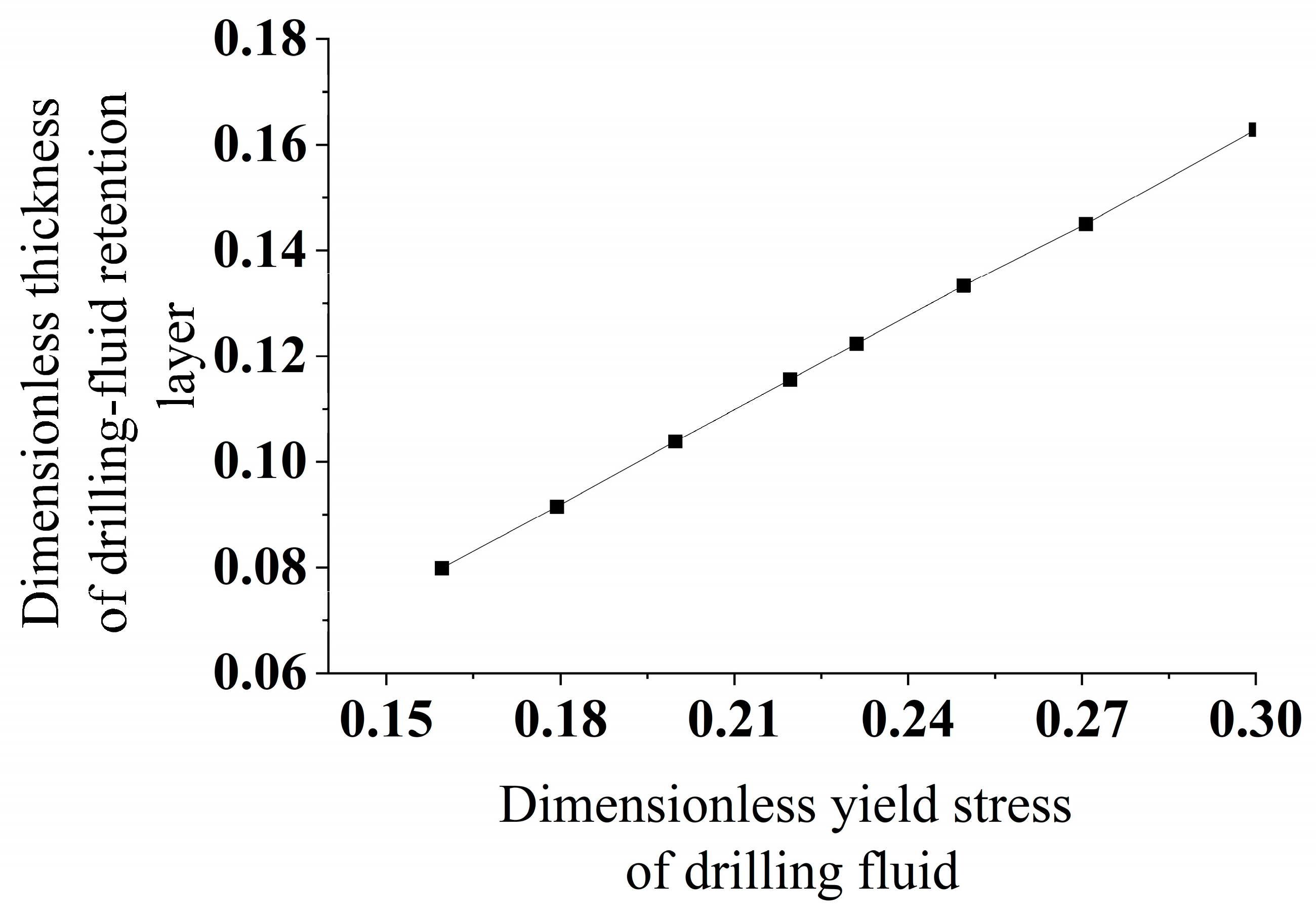
5.1.1. Effect of Drilling Fluid Yield Stress

To study the influence of drilling fluid yield stress, the basic data are taken for other parameters. The drilling fluid yield stress is taken as 0.16, 0.18, 0.2, 0.22, 0.25, 0.27 and 0.3, respectively. The thickness of drilling fluid retention layer under different yield stresses is calculated, as shown in Figure 4.
Based on the findings presented in Figure 4, it was observed that the thickness of the drilling fluid retention layer escalates in correlation with the rise in drilling fluid yield stress. This phenomenon can be attributed to the fact that the yield stress of drilling fluid represents the minimal shear stress required for the fluid to transition from a static state to a flowing state, thereby serving as a key indicator of the structural integrity of the drilling fluid in its static state. Thus, increasing the yield stress of drilling fluid is not conducive to the displacement of drilling fluid on the well wall and casing wall.
The above analysis indicates that a higher yield stress of drilling fluid is more beneficial for its carrying capacity, but it hinders displacement and can lead to drilling fluid retention between the wellbore and casing annulus. Therefore, it is necessary to evaluate and adjust the performance of drilling fluid before cementing on site, reduce the yield stress, and meet the requirements for cementing to prevent drilling fluid retention.

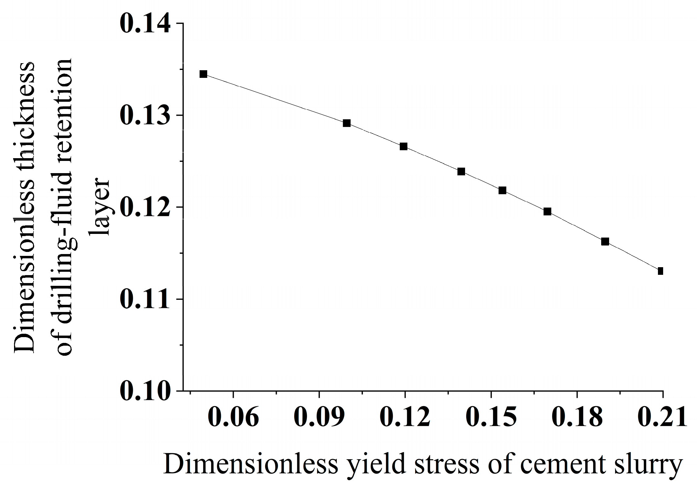
5.1.2. Effect of Yield Stress of Cement Slurry

The impact of the yield stress of cement slurry on the thickness of the drilling fluid retention layer is illustrated in Figure 5. The data indicate that elevating the yield stress of the cement slurry leads to a decrease in the thickness of the drilling fluid retention layer, thereby aiding in the prevention of cementing operation failure. By enhancing the yield stress of the cement slurry at the interface with the drilling fluid, the wall shear stress induced by the flow of cement slurry can be increased, promoting the expansion of the cement slurry flow profile from the annulus center towards the wall.
The above analysis indicates that increasing the yield stress and consistency coefficient of cement slurry is beneficial for reducing the thickness of the drilling fluid retention layer. However, it also increases the flow resistance of cement slurry, resulting in higher cement injection pressure, which may cause leakage in weak formations prone to low pressure and lead to the risk of cementing failure. Therefore, in on-site cementing and cementing operations, a comprehensive analysis is required to maintain the yield stress and consistency coefficient of cement slurry within a reasonable range.

5.1.3. Effect of Consistency Coefficient of Cement Slurry

The thickness of the drilling fluid retention layer is determined for various consistency coefficients of the cement slurry, as illustrated in Figure 6.
The data presented in Figure 6 illustrate that the impact of the consistency coefficient of cement slurry on the thickness of the drilling fluid retention layer is minimal. As the consistency coefficient of cement slurry rises, there is a decrease in the thickness of the drilling fluid retention layer to a certain degree.

5.1.4. Effect of Density Difference of Drilling Fluid

Alter the disparity in density between the cement slurry and drilling fluid, and proceed to determine the depth of the drilling fluid retention layer accordingly, as illustrated in Figure 7.
When the density of the cement slurry exceeds that of the drilling fluid, the buoyancy of the drilling fluid drives its flow. Enhancing the density contrast between the cement slurry and drilling fluid enhances the buoyancy effect, leading to a reduction in the thickness of the drilling fluid retention layer on the annulus wall as the density difference increases.

5.1.5. Effect of Well Inclination Angle

In the case of different well inclination angles, the thickness of the drilling fluid retention layer is calculated, and the results are shown in Figure 8. The results indicate that increasing the density difference between cement slurry and drilling fluid is more advantageous for improving displacement efficiency and reducing drilling fluid retention risk. Therefore, in the on-site cementing operation, considering formation pore pressure, fracture pressure, and other conditions, it is advisable to make the density difference between cement slurry and drilling fluid as large as possible, exceeding 0.2 g/cm3.
Under the same displacement conditions, the thickness of the drilling fluid retention layer on the annulus wall of the vertical well is smaller among different well types for the cement displacement. With the increase in well inclination angle, the component of buoyancy in the axial direction of the wellbore decreases. The reduction in buoyancy is not conducive to the displacement of drilling fluid on the annulus wall. The inclination angle significantly affects the retention of drilling fluid on the annular wall, but this factor cannot be changed. Therefore, it is necessary to conduct more in-depth research on the cementing of high-angle and horizontal wells.

5.2. Analysis on Thickness of Drilling Fluid Retention Layer in Eccentric Annulus

Casing eccentricity results in different velocities and flow patterns of cement slurry displacement at gaps with different sizes in the annulus. The thickness of the drilling fluid retention layer at various circumferential angles of the annulus is computed under varying casing eccentricity conditions, and the findings are presented in Figure 9.
The data presented in Figure 8 illustrate that the thickness of the drilling fluid retention layer within the annulus is consistent when the casing is centrally positioned within the wellbore. In contrast, when the casing is eccentric, the thickness of the drilling fluid retention layer is reduced at the wider annulus gap and is increased at the narrower annulus gap. Moreover, as the casing eccentricity intensifies, the disparity in thickness between the drilling fluid retention layers at the wider and narrower annulus gaps becomes more pronounced.

6. Quantitative Conditions for Absence of Drilling Fluid Retention on the Wall

Enhancing the efficiency of drilling fluid displacement is essential to mitigate issues such as fluid channeling and wall adherence during the drilling process. Based on the aforementioned model, the quantitative condition that there is no drilling fluid retention on the wall is analyzed, so as to provide a theoretical basis for reasonable adjustment of rheological parameters of cement slurry and drilling fluid and also for the cementing process.
Based on Equations (18) and (19), when Yi = H, the thickness of the layer of drilling fluid retained on the wall is 0. Substitute Yi = H into these two equations, we obtain
κ 1 H ( m 1 + 1 ) τ 2 , Y ( τ 2 , Y κ 1 τ 1 , Y κ 1 ) m 1 + 1 m 1 + 1 m 1 + 2 H + H · τ 1 , Y ( m 1 + 2 ) τ 1 , Y = H
The above equation is further simplified to
τ 2 , Y κ 1 τ 1 , Y κ 1 m 1 1 τ 1 , Y τ 2 , Y m 1 + 1 m 1 + 2 H + H m 1 + 2 · τ 1 , Y τ 2 , Y = m 1 + 1
Define parameters A and B to be
A = τ 1 , Y τ 2 , Y , B = τ 1 , Y κ 1
Parameter A represents the ratio of cement slurry yield stress to drilling fluid yield stress, and parameter B represents the ratio of cement slurry yield stress to cement slurry consistency coefficient. Substituting A and B into Equation (21), we obtain
B A B m 1 · 1 A m 1 + 1 m 1 + 2 H + H m 1 + 2 · A = m 1 + 1
Equation (23) indicates that a specific quantitative relationship must be satisfied between the rheological properties of cement slurry and drilling fluid in order to prevent any retention of drilling fluid on the wall. The relationship between parameters A and B is calculated by taking different liquidity indexes of cement slurry. When the liquidity index is given, B can be obtained if A is known; similarly, A can be obtained if B is known. Thus, the relationship between A and B can be a curve, as shown in Figure 10. For example, when the liquidity index of cement slurry is equal to 1 and parameter A is 0.7, it is required that parameter B needs to reach 17.3 for the drilling fluid to be removed completely. In Figure 10, the points that lie in the curve exactly and above the curve denote a situation where there is no retention of drilling fluid, i.e., the section below the curve represents a condition that there is a retention of drilling fluid. This can be analyzed based on the sensitivity analysis in Figure 4, Figure 5, Figure 6, Figure 7 and Figure 8. Take a point above the curve, for example, we can hold the opinion that when B is set to be constant (meanwhile, the yield stress of cement is set to be constant), A is larger than the value for no retention condition (i.e., the curve resulting from Equation (23)). In other words, the drilling fluid has a yield stress smaller than the value required to achieve no retention. Based on Figure 4, a smaller yield stress of drilling fluid leads to a smaller thickness of drilling fluid retention layer. Thus, there will be no retention of drilling fluid because the comparison object is the no-retention curve. Similarly, one can analyze the specific case using a given value of A, i.e., we can analyze the effects of B (or effect of consistency coefficient of cement slurry).

7. Case Analysis

Relevant slurry displaced by cement slurry consists of drilling fluid and pad fluid. Drilling fluid has yield characteristics; thus, when the drilling fluid is replaced by the pad fluid, it is easy to form a drilling fluid retention layer at the annulus wall, affecting the cementing performance. Equation (23) gives the quantitative relationship between the performance parameters of the displacing fluid and the displaced fluid when the drilling fluid retention layer is formed on the casing outer wall or well (formation) wall at different annular positions.
Here, we use the parameters of Well TH12366, which are listed below (the parameters of Well TH12366 is based on a real well in Tahe oilfield and is simplified slightly): the annular wellbore structure is Φ 215.9 mm × Φ 177.8 mm, casing eccentricity is set to be 0.3, and displacement is 0.6 m3/min (note: displacement of pad fluid in cementing design of Tahe Oilfield is 0.6~1.23/min). Levenberg–Marquardt method and general global optimization method were adopted to match the rheological parameters of pad fluids #1 and #2, which meet the Hershel–Bulkley model, and pad fluids #a and #b were regarded as the research control. The main rheological properties of relevant fluids are listed in Table 2.
As can be seen in Figure 11, Figure 12, Figure 13 and Figure 14, when the parameters (A, B) are located at the lower part of the curve, the drilling fluid is retained; when (A, B) is located at the upper part of the curve, there is no retention of drilling fluid. Increasing parameter A or dynamic plastic ratio B of pad fluid (preflush) is favorable for avoiding the formation of drilling fluid retention layer. In addition, the drilling fluid at the narrower gap of the eccentric annulus is easy to form a retention layer. If a drilling fluid retention layer does not develop within the confined space, there will be no such layer present at each gap within the annulus.
The displacement of drilling fluid with pad fluids #1, #2, #a, and #b in Table 2 is investigated. It can be seen from Figure 11, Figure 12, Figure 13 and Figure 14 that when the drilling fluid is displaced with pad fluids #1 and #2, there is no drilling fluid retention layer in the entire eccentric annulus; however, the drilling fluid will be retained on the annulus wall when the pad fluids #a and #b displace the drilling fluid.
The theoretical model presented can provide guidance for selecting various cementing parameters such as displacement capacity, drilling fluid density, cement slurry density, plastic viscosity, yield stress, liquidity index, and consistency coefficient. This model aims to minimize the thickness and determine the location of drilling fluid retention, as well as establish conditions to prevent the development of drilling fluid retention, based on specific well parameters including borehole size, casing size, well deviation angle, and casing eccentricity. Therefore, this study offers a theoretical framework for enhancing the displacement effectiveness of cement injection and maximizing the efficiency of cementing operations.

8. Conclusions

(1)
The characteristics of annulus fluid shear stress distribution are analyzed. Equations (7)–(9) suggest that if the yield stress of the drilling fluid exceeds that of the cement slurry, and the shear stress at the wall is lower than the yield stress of the drilling fluid, a specific thickness of drilling fluid retention layer will develop on the annulus wall.
(2)
The calculation model for the thickness of the drilling fluid retention layer is established, and the thickness of the drilling fluid retention layer is analyzed with parameters of wellbore and fluid performance: τ 1 , Y = 0.15 , κ 1 = 0.85 , n 1 = 1 , τ 2 , Y = 0.23 , ρ 2 = 0.75 , S t = 0.15 . The thickness of the drilling fluid retention layer is positively correlated with the drilling fluid yield stress and well inclination angle, while it is negatively correlated with the cement slurry yield stress, consistency coefficient of the cement slurry, and the density difference between the drilling fluid and cement slurry.
(3)
The thickness of drilling fluid retention layer in eccentric annulus is analyzed (i.e., eccentricity of 0, 0.1, 0.2, 0.3 are used). When the casing is not centered, the thickness of the layer of drilling fluid retained is smaller at the wider annulus gap and larger at the narrower annulus gap. As casing eccentricity increases, the disparity in the thickness of the drilling fluid retention layer between the wide and narrow gaps also increases.
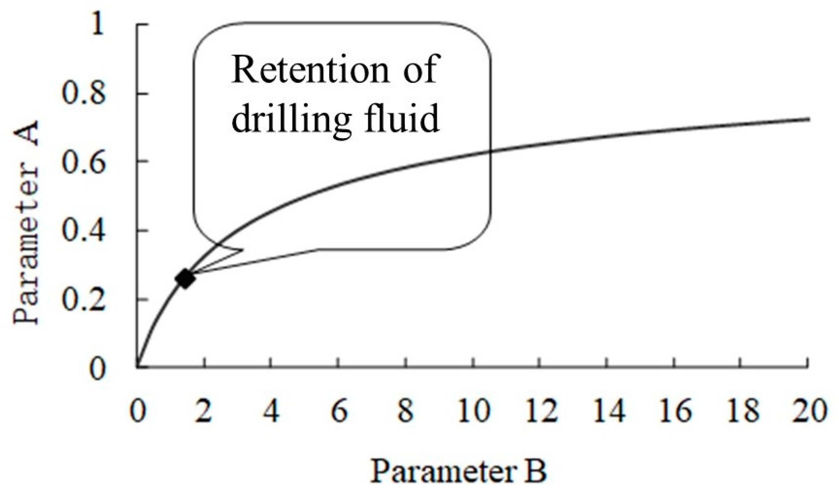
(4)
The quantitative conditions for preventing drilling fluid retention is established (i.e., Equation (23)). Based on Equation (23), a case study is conducted to show in which case the retention of drilling fluid can occur. When the parameters (A, B) are located at the lower part of the curve, the drilling fluid is retained; when (A, B) is located at the upper part of the curve, there is no retention of drilling fluid. The suggested theoretical framework can provide guidance for determining a set of cementing parameters, including displacement capacity, drilling fluid density, cement slurry density, plastic viscosity, yield stress, liquidity index, and consistency coefficient, based on a specific set of well parameters.

Author Contributions

Conceptualization, Z.W.; methodology, Z.W.; validation, C.W.; formal analysis, Z.C.; investigation, C.W.; data curation, Z.C. and Z.W.; writing—review and editing, Z.C.; supervision, C.W. All authors have read and agreed to the published version of the manuscript.

Funding

The authors greatly acknowledge the financial supports from the National Natural Science Foundation of China (No. 52288101; No. 51991361), an Independent Innovative Project (No. 20CX06015A) from China University of Petroleum (East China), State Key Laboratory of Offshore Natural Gas Hyrates project “Investigation of Response Pattern of Fiber Optic Monitoring for Integrity of Well Bore for Hydrate Formation Cementing” and the CNOOC Prophase Study project “Feasibility Study on Phase II Development of Wenchang 19-1 Oilfield” (No. 2022FS-04).

Data Availability Statement

The data presented in this study are available on request from the corresponding author. The data are not publicly available due to they relate to the team’s other research.

Conflicts of Interest

Author Zhiqiang Wu was employed by the CNOOC Research Institute Co., Ltd. The remaining authors declare that the research was conducted in the absence of any commercial or financial relationships that could be construed as a potential conflict of interest.

Nomenclature

Hhalf of the dimensionless annular-clearance width at a certain circumferential angle
Bthe length of the dimensionless ring gap at a circumferential angle
Yithe contact surface between cement slurry and drilling fluid, and 0 < YiH.
ξ ^ well depth
ξ dimensionless well depth
θcircumferential angle of annular space
βborehole well inclination, °
R ^ 1 ( ξ ^ ) the inner diameter of the borehole
R ^ 2 ( ξ ^ ) the outer diameter of the casing
W(y)the dimensionless velocity of the fluid
τ 1yield stress
τ 2shear stress of cementing slurry or drilling fluid
τ bshear stress of the fluid at the wall of two flat plates
τ Yishear stress of the fluid at the contact surface Yi
hstathe thickness of the drilling fluid retention layer
ŵ*cement slurry injection rate
ŵ(ŷ)cement slurry displacement rate
m1the reciprocal of cement slurry liquidity index
Parameter Athe ratio of cement slurry yield stress to drilling fluid yield stress
parameter Bthe ratio of cement slurry yield stress to cement slurry consistency coefficient

References

  1. Zheng, Y.; Fang, D.; Hao, J. A theoretical and experimental study of cementing for horizontal well. J. Hydrodyn. 1996, 11, 19–23. [Google Scholar]
  2. Cao, L.; Sun, J.; Zhang, B.; Lu, N.; Xu, Y. Sensitivity analysis of the temperature profile changing law in the production string of a high-pressure high-temperature gas well considering the coupling relation among the gas flow friction, gas properties, temperature, and pressure. Front. Phys. 2022, 10, 1050229. [Google Scholar] [CrossRef]
  3. Pelipenko, S.; Frigaard, I.A. On steady state displacement in primary cementing of an oil well. J. Eng. Math. 2004, 48, 1–32. [Google Scholar] [CrossRef]
  4. Bittleston, S.H.; Frigaard, I.A. Mud removal and cement placement during primary cementing of an oil well: Steady-state displacements. J. Eng. Math. 2004, 48, 1–26. [Google Scholar] [CrossRef]
  5. Frigaard, I.A.; Pelipenko, S. Effective and Ineffective Strategies for Mud Removal and Cement Slurry Design. In Proceedings of the SPE Latin American and Caribbean Petroleum Engineering Conference, Port-of-Spain, Trinidad and Tobago, 27–30 April 2003. SPE-80999-MS. [Google Scholar]
  6. Bittleston, S.H.; Ferguson, J.; Frigaard, I.A. Mud removal and cement placement during primary cementing of an oil well: Laminar non-Newtonian displacements in an eccentric annular Hele-Shaw cell. J. Eng. Math. 2002, 43, 229–253. [Google Scholar] [CrossRef]
  7. Beirute, R.M.; Flumerfelt, R.W. Mechanics of the Displacement Process of Drilling Muds by Cement Slurries Using an Accurate Rheological Model. In Proceedings of the SPE Annual Fall Technical Conference and Exhibition, Denver, CO, USA, 9–12 October 1977. SPE-6801-MS. [Google Scholar]
  8. Li, M.; Wang, C.; Guo, S.; Fang, Q. Numerical simulation of cement displacement in eccentric annulus at highly deviated wells. J. Pet. Drill. Tech. 2012, 40, 40–44. [Google Scholar]
  9. Yang, J.; Deng, J.; Feng, Y. Numerical simulation of effect of density difference on displacement efficiency at low cement slurry velocity. Pet. Drill. Tech. 2008, 36, 62–65. [Google Scholar]
  10. Couturier, M.; Guillot, D.; Hendriks, H.; Callet, F. Design rules and associated spacer properties for optimal mud removal in eccentric annuli. In Proceedings of the PETSOC Annual Technical Meeting, Calgary, AB, Canada, 9–12 June 1990. PETSOC-90-112. [Google Scholar]
  11. Lockyear, C.F.; Hibbert, A.P. Integrated primary cementing study defines key factors for field success. J. Pet. Technol. 1989, 41, 1320–1325. [Google Scholar] [CrossRef]
  12. Eslami, A.; Akbari, S.; Taghavi, S.M. An experimental study of displacement flows in stationary and moving annuli for reverse circulation cementing applications. J. Pet. Sci. Eng. 2022, 213, 110321. [Google Scholar] [CrossRef]
  13. Frigaard, I.A.; Renteria, A.; Sarmadi, P. Primary cementing of horizontal wells. Displacement flows in eccentric horizontal annuli. Part 2. Computations. J. Fluid Mech. 2021, 915, A83. [Google Scholar]
  14. Saasen, A.; Ytrehus, J.D. Rheological Properties of Drilling Fluids: Use of Dimensionless Shear Rates in Herschel-Bulkley and Power-law Models. Appl. Rheol. 2018, 28, 201854515. [Google Scholar]
  15. Saasen, A.; Ytrehus, J.D. Viscosity Models for Drilling Fluids—Herschel-Bulkley Parameters and Their Use. Energies 2020, 13, 5271. [Google Scholar] [CrossRef]
  16. Haut, R.C.; Crook, R.J. Primary Cementing: The Mud Displacement Process. In Proceedings of the SPE Annual Technical Conference and Exhibition, Las Vegas, NV, USA, 23–26 September 1979. [Google Scholar]
  17. Kroken, W.; Sjaholm, A.J.; Olsen, A.S. Tide Flow: A Low Rate Density Driven Cementing Technique for Highly Deviated Wells. In Proceedings of the IADC/SPE Drilling Conference, New Orleans, LA, USA, 12–15 March 1996. [Google Scholar]
  18. Tardy, P.M.; Flamant, N.C.; Lac, E.; Parry, A.; Sutama, C.S.; Almagro, S.P. New Generation 3D Simulator Predicts Realistic Mud Displacement in Highly Deviated and Horizontal Wells. In Proceedings of the SPE/IADC Drilling Conference and Exhibition, The Hague, The Netherlands, 14–16 March 2017. [Google Scholar]
  19. Tardy, P.M.J. A 3D model for annular displacements of wellbore completion fluids with casing movement. J. Pet. Sci. Eng. 2018, 162, 114–136. [Google Scholar] [CrossRef]
  20. Yang, M.; Yang, L.; Li, Y.; Zhang, L.; Wang, C.; Zhou, L.; Yang, M. Improving displacement efficiency by optimizing pad fluid injection sequence during primary cementing of eccentric annulus in shale gas horizontal wells. J. Pet. Sci. Eng. 2021, 204, 108691. [Google Scholar] [CrossRef]
  21. Carrasco-Teja, M.; Frigaard, I.A.; Seymour, B. Cementing Horizontal Wells: Complete Isolution without Casing Rotation. In Proceedings of the SPE Unconventional Resources Conference/Gas Technology Symposium, Calgary, AB, Canada, 16–19 June 2008. SPE-114955-MS. [Google Scholar]
  22. Liao, H.L.; Li, G.S.; Zhang, S.K. Theoretical analysis of cementing displacement mechanics of laminar flow for slim-hole. Pet. Drill. Tech. 2003, 31, 30–32. [Google Scholar]
Figure 1. Simplified model at a circumferential angle of annulus.
Processes 12 01176 g001
Figure 2. Schematic of buoyancy-driven flow regime.
Processes 12 01176 g002
Figure 3. Velocity profile shape during drilling fluid displacement by cement slurry (af).
Processes 12 01176 g003
Figure 4. Effect of drilling fluid yield stress on the thickness of drilling fluid retention layer.
Processes 12 01176 g004
Figure 5. The effect of cement slurry yield stress on the thickness of drilling fluid retention layer.
Processes 12 01176 g005
Figure 6. Influence of consistency coefficient of cement slurry on the thickness of drilling fluid retention layer.
Processes 12 01176 g006
Figure 7. Influence of variations in density on the thickness of the layer of drilling fluid retained.
Processes 12 01176 g007
Figure 8. Effect of well deviation angle on thickness of drilling fluid retention layer.
Processes 12 01176 g008
Figure 9. Analysis of thickness of drilling fluid retention layer in eccentric annulus.
Processes 12 01176 g009
Figure 10. The relationship between the rheological parameters of cement slurry and drilling fluid when the retention layer thickness of drilling fluid is zero.
Processes 12 01176 g010
Figure 11. Retention of drilling fluid displaced by pad fluid #1.
Processes 12 01176 g011
Figure 12. Retention of drilling fluid displaced by pad fluid #2.
Processes 12 01176 g012
Figure 13. Retention of drilling fluid displaced by pad fluid #a.
Processes 12 01176 g013
Figure 14. Retention of drilling fluid displaced by pad fluid #b.
Processes 12 01176 g014
Table 1. Properties of cement slurry and drilling fluid during cement displacement.
Density (kg/3)Liquidity IndexConsistency
Coefficient (Pa·sn)
Dynamic Shear (Pa)
Drilling fluid120010.36
Cement slurry150010.454
Table 2. Properties of drilling fluid for Well TH12366.
Fluid Property ParametersDensity
(kg/m3)
Liquidity IndexConsistency Coefficient
(Pa·sn)
Yield Stress
(Pa)
AB
Drilling fluid130010.0155------
Pad fluidPad fluid #114000.670.0821.7380.3481.047
Pad fluid #215000.86790.0442.5630.5131.183
Pad fluid #a15000.60.03520.43.864
Pad fluid #b15000.80.0251.50.31.653
Disclaimer/Publisher’s Note: The statements, opinions and data contained in all publications are solely those of the individual author(s) and contributor(s) and not of MDPI and/or the editor(s). MDPI and/or the editor(s) disclaim responsibility for any injury to people or property resulting from any ideas, methods, instructions or products referred to in the content.

