Article

Study on Activation and Restructuring of Key Strata in Shallowly Buried Coal Seam Bearing Structure and Load Characteristics

1
School of Energy, Xi’an University of Science and Technology, Xi’an 710054, China
2
Key Laboratory of Mine Mining and Disaster Prevention in West China, Ministry of Education, Xi’an University of Science and Technology, Xi’an 710054, China
*
Authors to whom correspondence should be addressed.
Processes 2024, 12(6), 1257; https://doi.org/10.3390/pr12061257
Submission received: 29 May 2024 / Revised: 14 June 2024 / Accepted: 17 June 2024 / Published: 18 June 2024
(This article belongs to the Section Energy Systems)

Abstract

:
The mining of shallow coal seam groups triggers the activation of overlying strata, leading to increased pressure and support difficulties, thereby posing a threat to the safe extraction of underlying coal seams. Against the backdrop of Longhua Coal Mine, this study utilized physical similarity simulation experiments to obtain the activated, restructured load-bearing structure and the migration characteristics of overlying strata. Theoretical calculations were employed to establish both a rolling friction mechanics model for the activated load-bearing structure and a mechanical model for the combined load-bearing structure of key strata. The research indicates that during the initial activation phase, the load-bearing structure exhibits a V-shaped hinged arch, with directly collapsed rock masses transitioning towards spherical shapes, resulting in the sub-key strata shifting from sliding friction to rolling friction. Based on the rolling friction mechanics model of the activated load-bearing structure, we derived the rolling friction coefficient of key blocks in the sub-key strata and the instability criterion of the load-bearing structure under rolling friction conditions. Considering the migration characteristics of the activated restructured load-bearing structure, four types of combined load-bearing structures were identified, and the load calculation formulas in the mechanical model were derived, with the rationality of these formulas verified through case analysis.

1. Introduction

Yushenfu Mining Area, positioned as the preferred energy base for the westward shift of China’s coal resource development strategy, boasts an accumulated proven coal reserve of 223.6 billion tons, approximately 25% of the nation’s total proven coal reserves, earning it recognition as one of the world’s eight major coalfields [1,2]. Characterized by shallow burial depth, near-horizontal seams, simple geological conditions, and high-quality coal, this mining area yields substantial extraction benefits [3,4]. However, with the extensive exploitation of coal resources, the initial mining seams have been nearly exhausted, prompting a transition to the mining of lower coal seams. This shift has revealed escalating high-intensity mining pressure, causing pronounced ground subsidence and posing significant challenges to the safety and efficiency of mine recovery [5,6,7]. The severe impact on mine safety and irreversible damage to the surface necessitate urgent research to elucidate the coupled evolution mechanism of strong mining pressure and surface subsidence.
A considerable amount of research has been conducted on the strong mining pressure and surface subsidence associated with the mining of shallow-buried coal seam groups, yielding valuable results [8]. Based on the key strata theory [9], various achievements have been proposed, including composite key strata [10,11], overlying rock fracture distance [12], shallow-buried coal seam definition [13], asymmetric three-hinged arch structure [14], surface step subsidence [15], and elliptical throw zones [16]. These contributions have laid the foundation for the study of shallow-buried coal seam group mining. Simultaneously, experts and scholars, in response to the multiple challenges encountered in mine operations, have put forward structural concepts such as cantilever beams and hinged rock beams and classification indicators for shallow-buried coal seam groups, as well as composite bearing structures for supporting rock layers [17,18,19]. Studies on surface subsidence have often focused on related research into filling mining, strip mining, and coordinated mining [20,21,22]. Due to the complexity of coal seam geological conditions and variations in coal seam exploitation, scholars worldwide have furthered research on the stress distribution characteristics during the mining process, the role of bearing structures, and the interactions between key strata fracture blocks [23,24]. Based on the geological characteristics of shallow-buried coal seams, it has been found that the bearing rock layers are prone to forming hinged rock beam structures and step rock beam structures after coal seam mining. Both types of rock beam structures exhibit stable bearing effects, but with differences in instability characteristics [25].
The secondary disturbance caused by the mining of lower coal seams and the increased free movement space led to the activation of overlying rocks in the upper coal seams. This results in the reformation of mechanically active structures in the critically stressed fracture blocks of the original mined-out area, providing support, inhibiting the movement of overlying rock layers, and reducing surface subsidence [26]. In the mining of shallow-buried coal seam groups, the working resistance of the support system in the lower coal seam mining is significantly greater than that in the upper coal seam mining. This is mainly attributed to the secondary activation of overlying rocks in the upper coal seams, leading to the transfer of the load of the overlying bearing structure to the support system in lower coal seams [27,28,29]. Simultaneously, the secondary activation of the bearing structure in upper coal seams causes the loosening of the ground layer, resulting in an increased subsidence space and subsequent surface settlement [30,31]. The stability of the key strata support structure in lower coal seam mining not only controls the interlayer rock movement characteristics but also has a significant impact on the activation degree of the upper coal seam and the secondary damage to the surface [32,33,34]. Furthermore, relevant scientific methods should be employed to address the movement of overlying strata in response to mining-generated waste [35,36]. Previous research has mostly focused on the key strata supporting the structure of individual upper and lower coal seams. While the research findings can guide on-site production, there are potential threats to on-site production due to deviations in the research results [37,38]. Therefore, the study of the mechanical mechanism of key strata support structures in shallow-buried coal seam group mining should focus on the joint mechanism between the key strata support structure in the lower coal seams and the activated support structure in the upper coal seams.
This paper, focusing on the context of shallow-buried coal seam group mining, conducts research on the key strata support structures of upper and lower coal seams through the methodology of similar simulation experiments. Building upon the foundation of similar simulation experiments, a rolling frictional mechanical model is established to determine the critical conditions for the instability of the support structures. By analyzing the migration characteristics of the key strata support structures during coal seam group mining, a mechanical calculation model for the activation and recombination of overlying rocks is developed. The study obtains the load calculation formula for the support system in lower coal seam mining, providing a theoretical basis for research on key strata support structures and support system loads in shallow-buried coal seam group mining.

2. Simulation Experiment Design for Activation and Recombination of Support Structures in Coal Seam Group Mining

2.1. Engineering Background

The Yushenfu Mining Area, as a representative region of shallow-buried coal seam occurrences in China, serves as the focus of this study. The geological and depositional conditions of the Longhua Coal Mine within this mining area provide the research background. The main coal seams being mined in the mine are 1-2, 2-2, and 3-2, with the present study focusing on the 1-2 and 2-2 coal seams. Currently, the 1-2 coal seam has undergone extensive extraction, while active extraction is underway for the 2-2 coal seam. The coal thicknesses for these seams are 2.95 m and 3.3 m, respectively, with model construction thicknesses of 3 m and 3.5 m. The dip angle ranges from 0 to 3 degrees, characterizing the coal seams as nearly horizontal. Comprehensive mechanized mining is employed, utilizing a fully caving method for roof management.
Three key strata layers coexist between the two coal seams. These layers are located at different distances above the coal seams, including a middle-grain sandstone layer (interlayer key strata) situated 14 m above the 2-2 coal seam, a coarse-grain sandstone layer (sub-key strata) positioned 12 m above the 1-2 coal seam, and a fine sandstone layer (main key strata) located 37 m above the same coal seam. The inter-seam rock layer has a thickness of 33.58 m, and an unconsolidated loess layer with a thickness of 18 m is present at the surface.

2.2. Similar Material Simulation Experiments

Based on the coal-rock mechanical characteristics and the geological and depositional conditions of the study area, a two-dimensional planar physical similarity simulation model was constructed. The experimental model has a length of 300 cm, a width of 20 cm, and a height of 155.5 cm, with a research height of 113 cm for this study. The geometric similarity constant for the model is 1/100, the time similarity constant is 1/10, and the velocity similarity constant is 1/10. Initially, the simulation models the extraction of the 1-2 coal seam, followed by the extraction of the 2-2 coal seam after the overlying rock stability is achieved. The mechanical parameters of the coal (rock) in the model are as shown in Table 1.
Displacement monitoring points were strategically placed on the surface of the model, and a total station was employed to record the displacement of measurement points during the coal seam extraction process. Seven displacement measurement lines were established within the research area. These lines were located at different levels above the 2-2 coal seam, specifically at 14 cm and 24 cm above the coal seam, and above the 1-2 coal seam at 12 cm, 23 cm, 37 cm, 53.5 cm, and 63.5 cm. The lines were sequentially labeled A to G from the bottom of the model for ease of reference. Subsequent descriptions will be based on the original prototype dimensions.

3. Analysis of Activation and Recombination of Key Strata Support Structures and Their Migration Characteristics

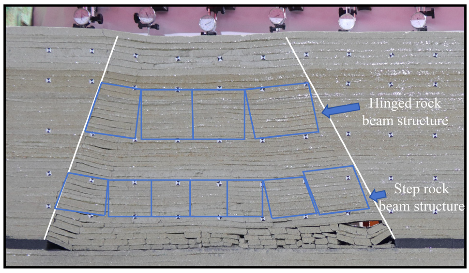
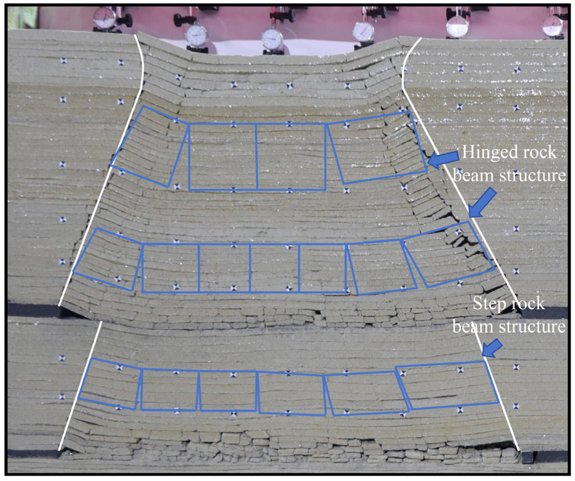
3.1. Fracture Characteristics of Key Strata during Shallow-Buried Coal Seam Mining

In order to investigate the fracture characteristics of key strata during the mining of shallow-buried coal seam groups, this study selected the Longhua Coal Mine with a layer spacing of 33.58 m and three coexisting key strata layers as the research background. The left side of the model was designated as the starting point for the advancing working face. After the stable extraction of the 1-2 coal seam, the extraction of the 2-2 coal seam was initiated, studying the fracture characteristics of key strata support structures in the overlying rocks during the extraction of each coal seam and the characteristics of the activation and recombination of support structures during the extraction of the 2-2 coal seam.
(1)
Fracture characteristics of key strata during the extraction of the 1-2 coal seam
Physical similarity simulations indicate that after the extraction of the 1-2 coal seam, a small separation layer forms directly at the roof, leading to its fracture and collapse, resulting in block-shaped fractures resembling spheres. Subsequently, the overlying rock layers sequentially undergo flexural deformation, and after reaching the limit deformation value of the rock layers, fractures and collapse occur. When the advancing working face reaches the initial fracture distance of the sub-key strata, fracture blocks form a three-hinge arch structure. The upper hinge point forms an articulated structure with the intact rock layers of the sub-key strata, while the lower hinge point falls on the directly collapsed roof block. After the rock layers fracture beneath the main key strata, there is no apparent bending deformation in the main key strata. As the excavation length of the working face increases, the sub-key strata fracture at a rock fracture angle of 73°, forming a stepped rock beam structure. The main key strata lag behind the fracture of the sub-key strata, with the lag distance being the tangent function of the height between the two key strata. Upon completion of the working face extraction, the sub-key strata form an articulated rock beam structure on the left side of the working face and a stepped rock beam structure on the right side. The main key strata form articulated rock beam structures on both ends of the working face. The sub-key strata and the main key strata jointly bear the overlying load, as shown in Figure 1.
(2)
Fracture characteristics of key strata during the extraction of the 2-2 coal seam
The 2-2 coal seam in the study area is located directly below the 1-2 coal seam, and both are excavated from the left end to the right end of the model in the same direction as the advancement of the 1-2 coal seam. In the early stages of model excavation, no bending deformation occurred in the immediate roof. As the excavation length increased, the amount of bending deformation increased, leading to the fracture and collapse of the rock layers, resulting in irregularly shaped collapsed rock blocks. When the excavation length of the model reached the critical fracture limit of the interlayer key strata for the 2-2 coal seam, the interlayer key strata experienced bending fracture and supported the overlying load in a three-hinge arch structure. Due to the influence of the rock fracture angle and the three-hinge arch structure, the length of the suspended rock layer at the top did not reach the limit fracture length of the rock layer. At this point, the fracture height of the rock layers was 26 m, and the length of the suspended rock layer above was the difference between the excavation length of the model and twice the tangent function of the fracture height of the rock layer. After the interlayer key strata experienced fracture again, the overlying rock layers above the 2-2 coal seam collapsed. The interlayer key strata underwent periodic cyclic fracture, forming a stepped rock beam structure. The overlying rock layers above the 1-2 coal seam underwent synchronized movement, with stabilized rock layers gradually activating in a manner similar to a cyclic process with a length equal to the original fractured rock block. The activated support structure of the sub-key strata transformed from a stepped rock beam structure to an articulated rock beam structure, while the main key strata maintained an articulated rock beam structure and controlled the sinking pattern of the loose loess layer below the ground surface, as shown in Figure 2.

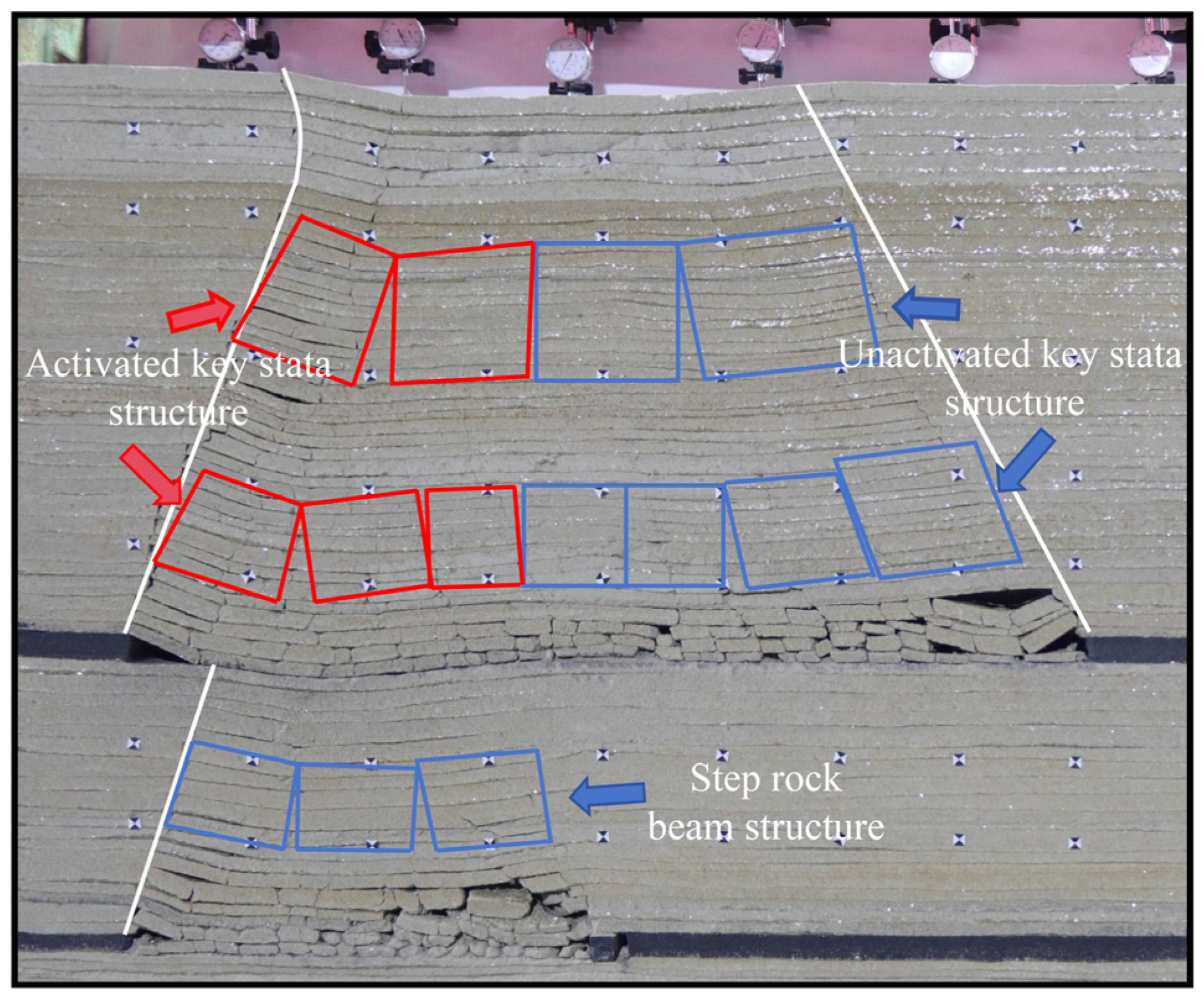
3.2. Activation Characteristics of Key Strata Support Structures

During the extraction of the lower coal seam, the instability and collapse of the inter-seam rock layers lead to the transformation of the key strata support structure in the overlying coal seam from a static state to a dynamic state, a process referred to as the activation of key strata support structures. The support structures that retain carrying capacity after activation are termed activated recombination support structures. Based on the experimental simulation observations, an analysis is conducted on the migration characteristics and activation process of the activated recombination support structures of key strata.
After the interlayer key strata fractures during the excavation of the 2-2 coal seam, the sub-key strata become activated, followed by the activation of the main key strata. At this point, the support structures of the three key strata in the study area, from bottom to top, are sequentially a stepped rock beam structure, an articulated rock beam structure, and another articulated rock beam structure. The rotation of the interlayer key strata fractures and the effect of the rock fracture angle during the extraction of the lower coal seam result in a funnel-shaped, V-shaped subsidence space in the activated rock layer zone of the overlying coal seam. The activation of the overlying rock layers from the 1-2 coal seam causes a reduction in the block size of the collapsed rock blocks in the immediate roof, further shaping them towards spherical forms. This transformation leads to the rock blocks below the sub-key strata transitioning from sliding to rolling in the V-shaped activated free movement space, forming a V-shaped articulated arch support structure. As the excavation position of the model gradually approaches the right end stopping point, the activated rock layers sequentially undergo movement with the fractured blocks of the key strata as units. The supporting rock blocks form supporting rock columns from bottom to top, controlling the movement of the overlying rock layers and the ground surface, as shown in Figure 3.

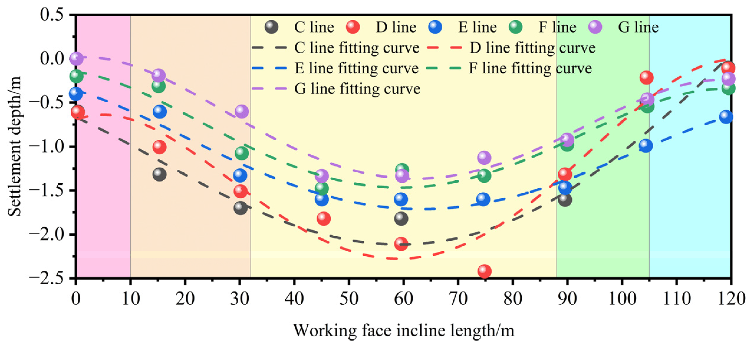
3.3. Movement Characteristics of Rock and Soil Layers in Shallow Coal Seam Group Mining

(1)
The characteristics of overburden movement due to coal seam mining
Through the analysis of five displacement measuring lines above the 1-2 coal seam and their fitting curves, the characteristics of the key strata bearing structure movement and surface subsidence are identified. As the excavation length of the model increases, the C measuring line located below the sub-key strata is the first to experience subsidence displacement, while the displacement sidelines above the sub-key strata do not move and remain stable. Following the fracture of the sub-key strata, the D and E measuring lines begin to move, with the displacement of the C line significantly exceeding that of the D and E lines, and the D line being the first to show a displacement inflection point. Due to the infilling effect between the sub-key and main-key strata, the subsidence of the E line is reduced compared to the D line. After the first cyclic fracture of the sub-key strata, the main key strata fractures and moves, leading to the synchronous subsidence of the F and G measuring lines, with their subsidence being less than that of the C to E lines. The subsidence fitting curves of the F and G lines are similar, with the G curve exhibiting stronger symmetry, indicating that the key strata exert significant control over the surface and that the surface has a mitigating effect on the subsidence shape of the key strata. Based on the characteristics and slopes of the subsidence fitting curves, the subsidence can be divided into three zones: a slow subsidence area ranging from 0 to 10 m and 105 to 120 m along the working face; a rapid subsidence area from 10 to 32 m and 88 to 105 m; and a stable subsidence area from 32 to 88 m. Due to the support of boundary coal pillars, the slow subsidence area experiences slower subsidence speed and a smaller subsidence slope. The rotational action of the key strata-bearing structure at both ends of the working face inclination leads to greater overburden and surface subsidence in the rapid subsidence area, with the highest subsidence slope. The stable subsidence area, located in the central part of the working face inclination, is where the key strata bearing structure has been compacted and stabilized, no longer forming a significant bearing structure. The D, E, F, and G fitting curves display distinct subsidence inflection points, with the specific subsidence shapes illustrated in Figure 4.
(2)
Characteristics of rock and soil layer movement in lower coal seam mining
The characteristics of overlying rock and soil layer movement during lower coal seam mining can be divided into two phases: the non-activated phase of the upper coal seam rock and soil layers and the activation phase. In the non-activated phase of overburden movement, due to the bearing action of the interlayer key strata, size effects, and the rock layer fracture angle, the A measuring line is the first to undergo vertical displacement, followed by horizontal displacement during the excavation of the lower coal seam. The displacement of the A measuring line is primarily determined by the mining height of the lower coal seam, the fill volume of the direct top rock layer, and the exposed length of the rock layer above the coal wall, with the greatest subsidence occurring in the middle part of the working face inclination. When the interlayer key strata do not fracture and collapse, the upper rock and soil layers do not activate and remain in their original static state. As the excavation length of the lower coal seam increases and the interlayer key strata fracture and collapse, the overlying rock and soil layers become activated, and their movement curve resembles a V-shape, with the rock layers sinking in a funnel-like manner. The rock and soil layers sink sequentially from the bottom up, exhibiting a certain lag. Due to the filling of rock blocks and the bearing action of the key strata, the subsidence of the overlying rock and soil layers decreases successively in the displacement monitoring areas of each coal seam.
The fitting curves of subsidence amounts from the displacement measuring lines indicate that the slope of the subsidence fitting curve on the left side of the model is greater than that on the right side, with the slope of the fitting curve in the middle region of the model approaching zero. Due to the bearing action of the key strata, the fitting curves of the measuring lines located within the control area of the key strata exhibit strong similarity, indicating the key strata’s role in controlling the movement of the overlying rock and soil layers. For the displacement fitting curves in the activated region, the overall shape of the curve is V-shaped, indicating that after activation, the rock layers move in an approximately symmetrical manner, with the activated rock layers sequentially activating upwards by layer. A comparison of the fitting curves in Figs 4 and 5 reveals that the mining of the lower coal seam leads to the activation of the upper coal seam rock and soil layers, increasing the slope of the subsidence fitting curves and enhancing the symmetry of the subsidence shape. The monitoring data show that only the F and G fitting curves have obvious inflection points on both sides of the model, indicating that the activation of the rock and soil layers increases the overall subsidence amount, causing secondary damage to the surface and overlying rocks, with an intensified degree of damage, as shown in Figure 5.

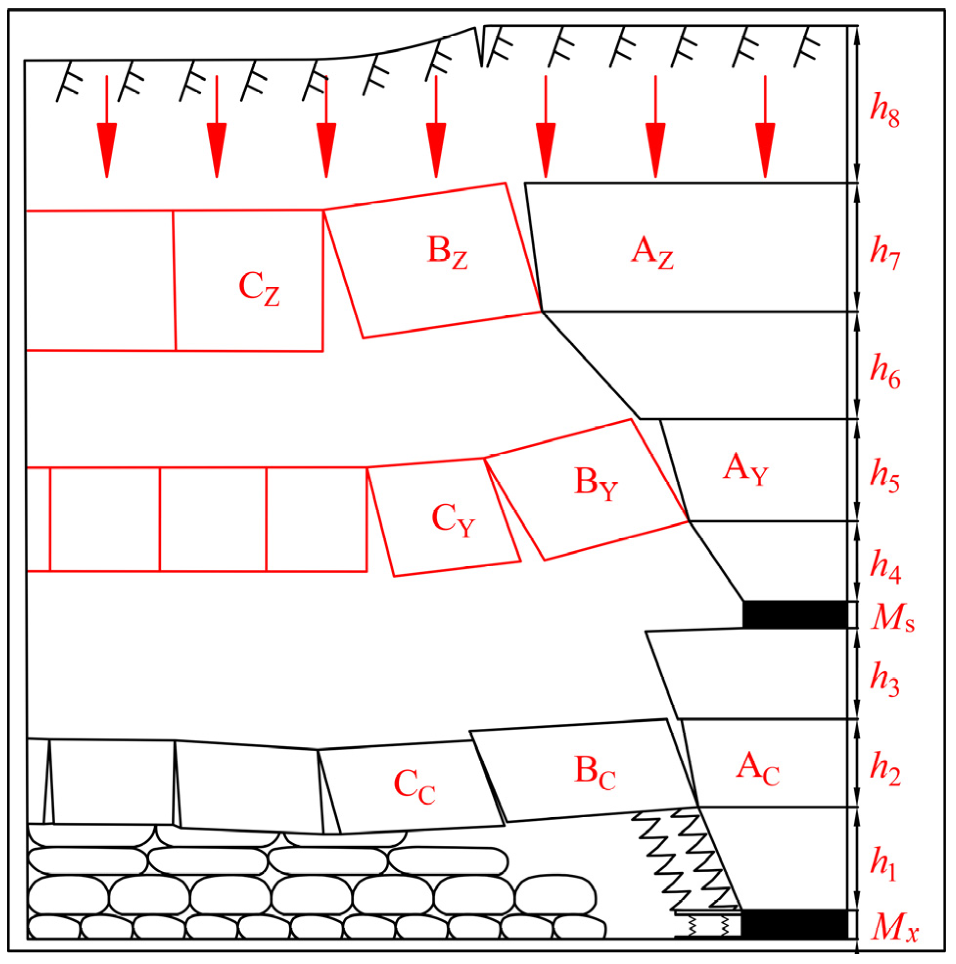
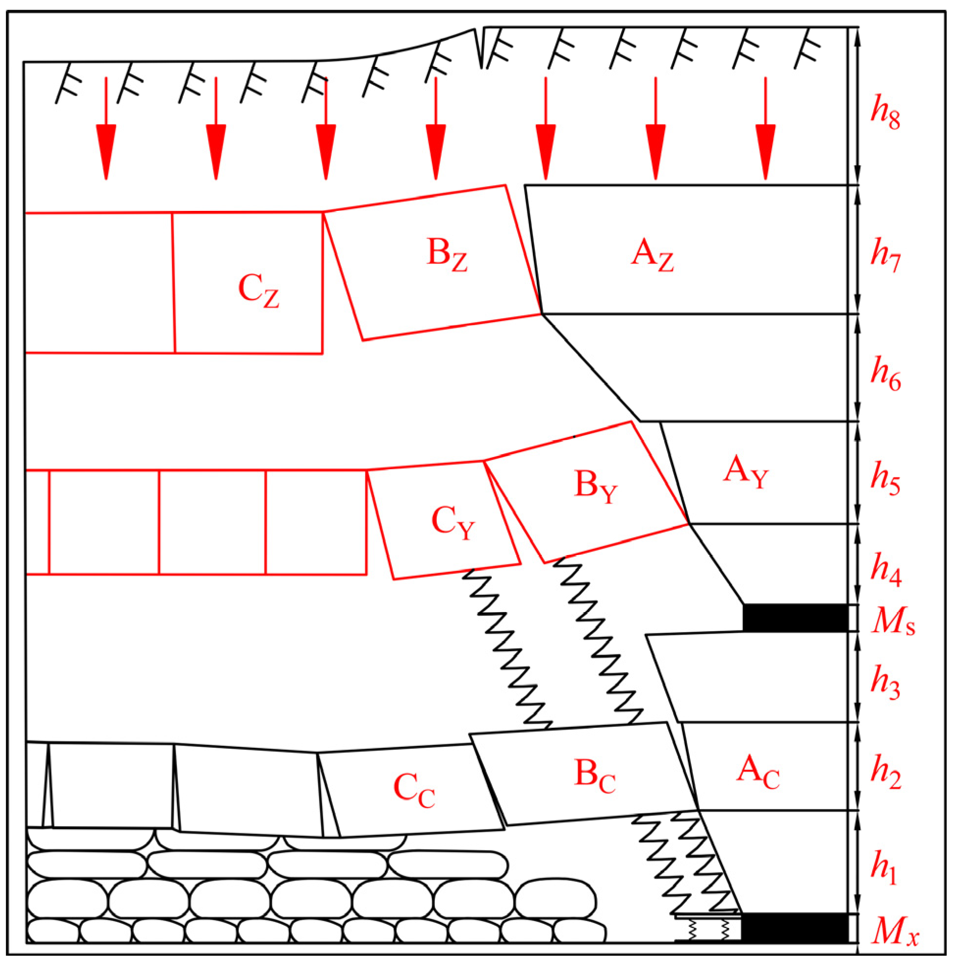
4. Mechanical Mechanisms of Rolling Friction in Activated Key Strata Bearing Structures and Stability Assessment

4.1. Construction of Mechanical Models

From the masonry beam theory, it is known that the fractured blocks of the key strata act as bearing bodies in the form of hinged rock beam structures and stepwise rock beam structures, whose stability directly determines the bearing capacity of the overlying rock layers. Based on the results of physical similarity simulation experiments, the repeated disturbance effect of mining the lower coal seam promotes the activation of overlying rock in the upper coal seam, reduces the size of the rock fracture blocks, and transforms the collapsed rock blocks in the goaf’s direct top into irregular spheroids. The directly collapsed rock blocks of the upper coal seam, along with the sub-key strata, show signs of rolling when moving towards the V-shaped subsidence space of the goaf. To simplify the study, the working-face inclination section is used as the research reference plane, and the directly collapsed rock blocks are regarded as regular spheroids. At this point, the sliding friction between the sub-key strata, the directly collapsed rock blocks of the 1-2 coal seam, and the interlayer rock layers is transformed into rolling friction, significantly reducing the frictional resistance and increasing the instability probability of the bearing structure. Therefore, it is urgent to study the mechanical mechanism of key strata bearing structures under rolling friction conditions.
Based on the aforementioned research needs, the mechanical relationship between the activated bearing structure of the sub-key strata during the mining of the lower coal seam and the directly collapsed rock layers in the goaf is simplified to a spherical rolling friction mechanical structure model, as shown in Figure 6.
In Figure 6, P represents the load from the overlying strata on the sub-key strata fracture block, kN; T denotes the horizontal thrust between critical blocks, kN; Ti is the horizontal thrust component from the rolling sphere, kN; Pi indicates the load from the overlying strata on the sphere, kN; F is the force of interaction between the sphere and the interlayer rock, kN; Fv is the component of the force F perpendicular to the interlayer rock, kN; Fh is the component of the force F parallel to the interlayer rock, kN; M stands for the moment of force due to the squeezing action between the sphere and the interlayer rock at point O1, kN·m; FN is the resultant force of Fv and the equivalent action force of M, kN; d is the distance from the moment M to point O1, m; θ T represents the angle of the activated V-shaped subsidence slope on the upper coal seam, °.

4.2. Analysis of the Rolling Friction Mechanics in the Activation of Key Strata Bearing Structures

Mining in the lower coal seam leads to the activation of overlying strata in the upper coal seam, thereby increasing the height of the free movement space of the overburden. At this point, the height of the free movement space hy is
h y = M x ( K P 1 ) H C
where Mx represents the mining height of the lower coal seam, m; KP denotes the swelling coefficient of the overburden backfill in the lower coal seam; and HC is the interlayer distance between the upper and lower coal seams, m.
Due to the mining of the lower coal seam, the fracture of the interlayer key stratum leads to the formation of a stepped rock beam structure, causing the critical blocks to undergo rotational subsidence. Concurrently, based on the control exerted by the key strata bearing structure on the overlying strata, a V-shaped subsidence slope is formed in the goaf of the upper coal seam, with the slope angle θ T being
θ T = arctan h 5 L y
where h5 represents the thickness of the sub-key strata, m, and Ly denotes the fracture length of the critical block in the sub-key strata, m.
According to the masonry beam theory, the criterion for the stability of the rock beam structure can be determined as
Q T tan φ
where Q represents the shear force between rock blocks in the key strata bearing structure, kN, and tan φ is the coefficient of friction for the rock mass, taken as 0.5.
When mining in the lower coal seam creates a migration space, at this time, the horizontal thrust T of the sub-key strata bearing structure is the rolling friction force of the rock strata, which can be expressed as
T = F g
Based on the force interaction at the contact point O1 of the sphere, the rolling resistance coefficient δ can be obtained as
δ = d = M / F N
Based on the principle of force system equilibrium M A ( F ) = 0 , substituting Equation (5) into the moment balance equation yields the rolling friction force Fg of the sphere as
F g = M R = δ F N R = δ P R
where R represents the radius of the rolling rock block, which can be taken as half the length of the working face advance.
At this point, the horizontal thrust T of the sub-key strata fracture bearing structure can be expressed as
T = F g = δ P R
Due to the presence of a certain number of directly collapsed rock blocks beneath the critical block of the sub-key strata, multiple spherical bodies form under secondary disturbances and exhibit a tendency to roll and transfer. To simplify the calculation, an analysis of the rolling friction force state on a single spherical body is conducted, as shown in Figure 6a.
Based on the force characteristics of the sub-key strata, solving for the mechanical components of the ith rolling sphere yields
{ P = P i sec θ T T i csc θ T T = P i csc θ T + T i sec θ T
By substituting Equation (6) into Equation (8), the calculation expressions for P and T can be obtained as
{ P = P i sec θ T δ O F i R csc θ T T = P i csc θ T + δ O F i R sec θ T
where δ O represents the rolling resistance coefficient of the sphere between simple interfaces, which can be obtained through experimental testing.
By substituting Equations (7) and (9) into Equation (4), the rolling resistance coefficient δ i of the sphere can be obtained as
δ i = R 2 P i csc θ T + R δ O F i sec θ T R P i sec θ T δ O F i csc θ T
The immediate roof rock layer typically exhibits characteristics of caving as mining progresses, meaning that after multiple collapses of the immediate roof, the sub-key strata undergoes a periodic fracture. Assuming that the immediate roof collapses n times before a single fracture occurs in the sub-key strata, the rolling friction coefficient δ i y of the critical block in the sub-key strata can be determined as
δ i y = i n R 2 P i csc θ T + R δ O F i sec θ T R P i sec θ T δ O F i csc θ T

4.3. Stability Assessment of Activated Bearing Structures

When the lower coal seam is mined without disturbing the upper coal seam (Figure 7a), the sub-key strata are not activated. As the mining of the lower coal seam activates the sub-key strata (Figure 7b), a V-shaped subsidence space forms, the originally stable structure of the sub-key strata is activated, rotating towards the goaf, and a hinged structure forms between the critical blocks. Due to the multiple disturbances from coal seam mining and the characteristics of object migration, the hinge points between critical blocks L2 and L3 in the sub-key strata are destroyed, leading to rotational migration and rolling movement of the critical blocks (Figure 7c). With the increase in the length of the activated sub-key strata, the not yet activated critical block L4 tends to rotate towards the goaf and gradually becomes activated, while the activated critical block L3 moves towards critical block L4. Critical block L4 rolls towards the goaf along the V-shaped slope angle θ T (Figure 7d). As the activated space continues to expand, critical block L5 undergoes periodic rolling movement along the slope angle θ T (Figure 7e), as shown in Figure 7, illustrating the migration characteristics of activated critical blocks in the sub-key strata bearing structure.
Based on the rotational characteristics of the critical blocks in the hinged structure and the rotational angle of the critical blocks (Figure 7), assuming that the fracture lengths of the critical blocks are equal to Ly, the condition for the critical blocks not undergoing rolling migration is
L y h y tan φ y b 1 cos θ T
where b represents the length of the hinge point damage between critical blocks L2 and L3, m, and φ y denotes the fracture angle of the rock layers in the sub-key strata, °.
Due to the activation of the overlying rock structure in the upper coal seam causing plastic damage to the critical blocks at the contact hinge, based on the condition for judging the rotational deformation instability of the bearing structure’s critical blocks, the condition a under which the activated bearing structure does not undergo deformation instability can be obtained as
a δ i y P η σ c R
where η σ c represents the compressive strength of the critical block at the contact hinge, m.
From the geometric relationship of the fractured critical blocks in the key strata, b can be determined as
b = δ i y P sec φ y η σ c R
By substituting Equation (14) into Equation (12), the condition for the critical blocks not undergoing rolling migration can be determined as
L y h y tan φ y δ i y P sec φ y η σ c R 1 cos θ T
From the calculation formula for the sliding instability of the hinged rock beam structure, along with Equations (3), (7), and (11), the discriminant for sliding instability of the sub-key strata bearing structure after activation can be derived as
δ i y Q R P tan φ y

5. Mechanical Characteristics of Activated and Restructured Key Strata Bearing Structures

Based on the migration characteristics of the main key strata, sub-key strata bearing structures, and interlayer key strata bearing structures during coal seam mining, the load mechanics models of key strata bearing structures can be categorized into four types: the key strata bearing structure without synchronous migration load mechanics model, the key strata bearing structure instability load mechanics model, the sub-key strata activated bearing structure with synchronous migration load mechanics model, and the key strata activated bearing structure with synchronous migration load mechanics model.

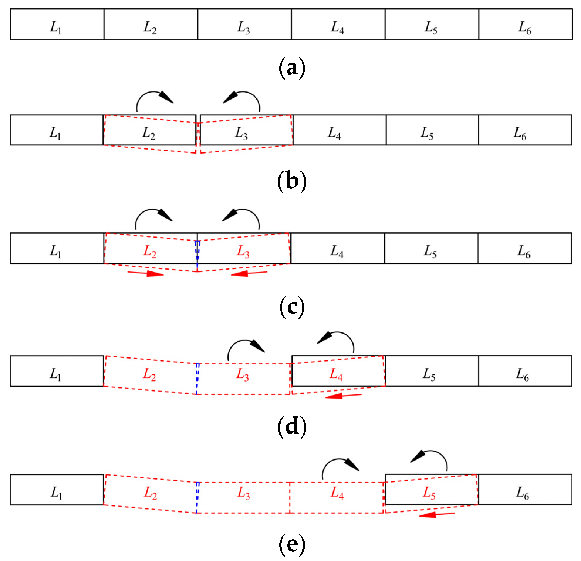
5.1. Analysis of Non-Synchronous Migration Load Characteristics of Key Strata Bearing Structures

(1)
Analysis of the key strata bearing structure without synchronous migration load mechanics model
During the mining of the lower coal seam, when the main key strata and sub-key strata bearing structures are activated and there is no synchronous migration with the interlayer key strata, the mechanical model of the bearing structure is as shown in Figure 8.
In Figure 8, Mx represents the mining height of the lower coal seam, m; Ms is the mining height of the upper coal seam, m; h1 denotes the thickness of the immediate roof of the lower coal seam, m; h2 is the thickness of the interlayer key strata, m; h3 stands for the thickness of the interlayer rock, m; h4 is the thickness of the immediate roof of the upper coal seam, m; h5 represents the thickness of the sub-key strata, m; h6 denotes the thickness of the intervening rock layer, m; h7 stands for the thickness of the main key strata, m; and h8 is the thickness of the loess loose layer, m.
This model investigates the load during the mining of the lower coal seam when three key strata migrate non-synchronously. The non-synchronous migration of key strata prevents the formation of a concentrated load in the overlying strata. The load transferred from the overburden to the hinged rock beam structure of the sub-key strata onto the step rock beam structure of the interlayer key strata is relatively small and can be neglected. At this time, the load on the interlayer key strata step rock beam structure primarily includes the load of the immediate roof of the upper coal seam, the load of the interlayer rock, and the self-weight of the interlayer key strata critical block BC. Therefore, the support resistance PZ of the face end support is
P Z = W XZ + R C
W XZ = γ 1 h 1 l k b k
where WXZ represents the load of the immediate roof of the lower coal seam, kN; RC is the load transferred by the step rock beam structure of the interlayer key strata, kN; γ 1 denotes the bulk density of the immediate roof of the lower coal seam, kN/m3; lk is the control length of the roof by the end support, m; and bk is the width of the end support, m.
From the calculation formula for the load transferred by the step rock beam structure, RC can be determined as
R C = ( i C sin θ Cmax + sin θ C 0.5 i C 2 sin θ Cmax + sin θ C ) b k P SC
where iC is the blockiness of the fracture block in the interlayer key strata; θ Cmax is the maximum rotation angle of the critical block BC, °; θ C is the rotation angle of the critical block BC, °; and PSC is the force exerted by the step rock beam structure of the interlayer key strata, kN.
The force exerted by the step rock beam structure of the interlayer key strata PSC can be expressed as
P SC = P CB + P CY
where PCB represents the self-weight of the critical block BC in the step rock beam structure of the interlayer key strata, kN, and PCY denotes the overburden load on the critical block BC from the interlayer key strata to the sub-key strata step rock beam structure, kN.
Based on the characteristics of load transfer, the calculation formulas for PCB and PCY can be obtained as
{ P CB = γ 2 h 2 L CB P CY = ( γ 3 h 3 + γ 4 h 4 ) L CB
where γ 2 represents the bulk density of the interlayer key strata, kN/m3  γ 3 is the bulk density of the interlayer rock, kN/m3; γ 4 denotes the bulk density of the immediate roof of the upper coal seam, kN/m3; and LCB is the fracture length of the critical block BC, m.
By substituting Equations (18)–(21) into Equation (17), the support resistance PZ of the face end support in the lower coal seam working face can be obtained as
P Z = γ 1 h 1 l k b k + ( i C sin θ Cmax + sin θ C 0.5 i C 2 sin θ Cmax + sin θ C ) ( γ 2 h 2 + γ 3 h 3 + γ 4 h 4 ) L CB b k
(2)
Analysis of the key strata bearing structure instability load mechanics model
During the mining of the lower coal seam, the activation of the main key strata and sub-key strata bearing structures exhibits various states of instability, applying load to the interlayer key strata bearing structure. The mechanical model is as shown in Figure 9.
This model investigates the load during the mining of the lower coal seam when the upper coal seam bearing structure becomes unstable. Under these model conditions, based on whether the main key strata and sub-key strata exhibit instability, they can be divided into three categories: sub-key strata stable, sub-key strata unstable, and both sub-key strata and main key strata simultaneously unstable.
(a)
Stability of the sub-key strata
When the sub-key strata are activated without instability, its bearing capacity is relatively high, and the load transferred to the lower coal seam is minimal and can be neglected. At this time, the support resistance of the face end support in the lower coal seam working face is the same as the support resistance of the key strata bearing structure without the synchronous migration load mechanics model shown in Figure 8, hence the load calculation formula remains the same and is not further analyzed.
(b)
Instability of the sub-key strata
When the sub-key strata become unstable upon activation, the main key strata plays a major role in bearing the overlying load, with the load transferred to the intervening rock layer being negligible. At this point, the overlying strata controlled by the sub-key strata can be considered to have a uniformly distributed load, with an effective load transfer coefficient denoted by KG.
The force exerted by the step rock beam structure of the interlayer key strata PSC is
P SC = ( P CB + P CY + P YB + P JG ) K G
where PJG represents the load on the intervening rock layer, kN; PYB denotes the load on the critical block BY of the sub-key strata, kN.
The calculation formulas for the load PYB on the critical block BY of the sub-key strata and the load PJG on the intervening rock layer are
{ P YB = γ 5 h 5 L YB P JG = γ 6 h 6 L YB
where γ 5 represents the bulk density of the sub-key strata, kN/m3; γ 6 denotes the bulk density of the intervening rock layer, kN/m3; and LYB is the fracture length of the critical block BY in the sub-key strata, m.
Based on the characteristics of load transfer, by substituting Equations (18), (19), (21), (23), and (24) into Equation (17), the support resistance PZ of the face end support in the lower coal seam working face can be obtained as
P Z = γ 1 h 1 l k b k + ( i C sin θ Cmax + sin θ C 0.5 i C 2 sin θ Cmax + sin θ C ) ( ( γ 2 h 2 + γ 3 h 3 + γ 4 h 4 ) L CB + ( γ 5 h 5 + γ 6 h 6 ) L YB ) K G b k
(c)
Simultaneous instability of sub-key strata and main key strata
Due to the destabilization of the sub-key strata leading to the instability of the main-key strata, at this point, the load on the overlying strata of the interlayer key strata can be considered uniformly distributed. The force exerted by the step rock beam structure of the interlayer key strata PSC is
P SC = ( P CB + P CY + P YB + P JG + P S + P ZB ) K G
The load PS on the loess loose layer and the load PZB on the critical block BZ of the main key strata are
{ P S = γ 8 h 8 L ZB P ZB = γ 7 h 7 L ZB
where γ 7 represents the bulk density of the main key strata, kN/m3; γ 8 denotes the bulk density of the loess loose layer, kN/m3; and LZB is the fracture length of the critical block BZ in the main key strata, m.
Based on the characteristics of load transfer, by substituting Equations (18), (19), (21), (24), (26), and (27) into Equation (17), the support resistance PZ of the face end support in the lower coal seam working face can be obtained as
P Z = γ 1 h 1 l k b k + ( i C sin θ Cmax + sin θ C 0.5 i C 2 sin θ Cmax + sin θ C ) ( ( γ 2 h 2 + γ 3 h 3 + γ 4 h 4 ) L CB + ( γ 5 h 5 + γ 6 h 6 ) L YB + ( γ 7 h 7 + γ 8 h 8 ) L ZB ) b k K G

5.2. Synchronous Migration Load Characteristics Analysis of Key Strata Bearing Structures

(1)
Analysis of the synchronous migration load mechanics model for sub-key strata activated bearing structures
During the mining of the lower coal seam, the activation of the main key strata and sub-key strata bearing structures does not result in synchronous migration. When the activated bearing structure of the sub-key strata synchronously migrates with the interlayer key strata, the mechanical model of the bearing structure is as shown in Figure 10.
This model studies the support load during the mining of the lower coal seam when there is synchronous migration between the sub-key strata and the interlayer key strata. Due to the asynchronous migration of the main key strata, the overlying strata cannot form a concentrated load. The load from the main key strata’s hinged rock beam structure transferred to the interlayer key strata’s step rock beam structure is negligible. At this time, the load on the interlayer key strata’s step rock beam structure mainly includes the load of the intervening rock layer, the force from the sub-key strata, the load of the immediate roof of the upper coal seam, the load of the interlayer rock, and the self-weight of the interlayer key strata critical block BC. Therefore, the force exerted by the interlayer key strata’s step rock beam structure PSC is
P SC = P YB + P CY + P YJ
where PYJ represents the force exerted by the hinged rock beam structure of the sub-key strata, kN.
Given that the bearing structure of the sub-key strata is a hinged rock beam structure, according to the masonry beam load calculation formula, PYJ can be obtained as
P YJ = 4 i Y ( 1 sin θ Y ) 3 sin θ Y cos θ Y 4 i Y + 2 i Y sin θ Y ( cos θ Y 2 ) ( P JG + P YB )
where iY represents the blockiness of the fracture block in the sub-key strata, and θ Y denotes the rotation angle of the critical block BY, °.
By substituting Equations (18), (19), (21), (24), (29), and (30) into Equation (17), the support resistance PZ of the face end support in the lower coal seam working face can be obtained as
P Z = γ 1 h 1 l k b k + ( i C sin θ Cmax + sin θ C 0.5 i C 2 sin θ Cmax + sin θ C ) ( ( γ 2 h 2 + γ 3 h 3 + γ 4 h 4 ) L CB + 4 i Y ( 1 sin θ Y ) 3 sin θ Y cos θ Y 4 i Y + 2 i Y sin θ Y ( cos θ Y 2 ) ( γ 6 h 6 + γ 5 h 5 ) L YB ) b k
(2)
Analysis of the synchronous migration load mechanics model for activated key strata bearing structures
During the mining of the lower coal seam, the activated bearing structures of the main key strata, sub-key strata, and interlayer key strata bearing structures form a synchronously migrating bearing rock column. The mechanical model is as shown in Figure 11.
This model investigates the load during the mining of the lower coal seam when the main key strata, sub-key strata, and interlayer key strata synchronously migrate. At this time, the load on the interlayer key strata’s step rock beam structure mainly includes the load of the loess loose layer, the force from the main key strata, the load of the intervening rock layer, the force from the sub-key strata, the load of the immediate roof of the upper coal seam, the load of the interlayer rock, and the self-weight of the interlayer key strata critical block BC. Therefore, the force exerted by the interlayer key strata’s step rock beam structure PSC is
P SC = P YB + P CY + P YJ + P ZJ
Given that the bearing structure of the main key strata is a hinged rock beam, according to the masonry beam load calculation formula, PZJ can be obtained as
P ZJ = 4 i Z ( 1 sin θ Z ) 3 sin θ Z cos θ Z 4 i Z + 2 i Z sin θ Z ( cos θ Z 2 ) ( P S + P ZB )
By substituting Equations (18), (19), (21), (24), (30), (32), and (33) into Equation (17), the support resistance PZ of the face end support in the lower coal seam working face can be obtained as
P Z = γ 1 h 1 l k b k + ( i C sin θ Cmax + sin θ C 0.5 i C 2 sin θ Cmax + sin θ C ) b k ×                   ( ( γ 2 h 2 + γ 3 h 3 + γ 4 h 4 ) L CB + 4 i Y ( 1 sin θ Y ) 3 sin θ Y cos θ Y 4 i Y + 2 i Y sin θ Y ( cos θ Y 2 ) ( ( γ 6 h 6 + γ 5 h 5 ) L YB + 4 i Z ( 1 sin θ Z ) 3 sin θ Z cos θ Z 4 i Z + 2 i Z sin θ Z ( cos θ Z 2 ) ( ( γ 7 h 7 + γ 8 h 8 ) L ZB ) ) )

5.3. Validation through Engineering Case Studies

In Longhua Coal Mine, the mining height for coal seam 1-2 is 2.95 m with a depth of 71.08 m, and for coal seam 2-2, the mining height is 3.3 m with a depth of 107.61 m. The thickness of the loess layer is 18.1 m, the main key strata is 16.63 m, the intervening rock layer is 14.27 m, the sub-key strata is 10.77 m, the immediate roof of coal seam 1-2 is 11.31 m, the interlayer rock is 11.92 m, the interlayer key strata is 8.02 m, and the immediate roof of coal seam 2-2 is 13.64 m. The average fracture length of the main key strata is 15.2 m, the sub-key strata is 14.5 m, and the interlayer key strata is 14.3 m. The bulk density of rock layers is taken as 26 kN/m3, and that of the loess loose layer as 23 kN/m3. The maximum roof control distance of the working face is 5.72 m, with a support width of 1.75 m. The maximum rotation angle of the critical block is 8°, with an average rotation angle of 5°.
This section does not determine stability due to bearing structure instability, as it has already been considered in the study of support load in the lower coal seam. Substituting the above parameters into Equations (22), (25), (28), (31), and (34), the working resistance of supports under different reorganized bearing structure cycles due to the activation of key strata can be obtained. Calculations show that the support resistance reaches its maximum when the key strata bearing structure is activated and synchronously migrates, with the maximum value of PZ being
P Z = 12732.35   kN
The mine selected hydraulic supports with a rated working resistance of 14,000 kN per support. According to on-site dynamic load measurements during mining pressure occurrences, the dynamic load factor was 1.43, with the actual maximum support resistance measured at 13,800 kN. The presence of dynamic loads was evident, and the theoretical calculations were essentially consistent with the data measured by on-site operators, meeting the requirements for safe production. This consistency validates the rationality of the calculation formula.

6. Conclusions

(1)
Through physical similarity simulation, it was found that mining in the lower coal seam prompts the activation of overlying strata in the upper coal seam, forming a reorganized bearing structure that exerts a bearing effect on the overlying strata. At the initial stage of bearing structure activation, it presents as a V-shaped hinged arch, the blockiness of the immediate roof decreases, and the rock blocks tend to become spherical, which facilitates the transition of the sub-key strata from sliding friction to rolling friction.
(2)
Based on the rolling friction characteristics of the load-bearing structure, a mathematical model for calculating the rolling friction of the activated load-bearing structure of the key stratum was constructed. The coefficient of rolling friction for the key blocks of the subkey strata and the stability criterion of the load-bearing structure under rolling friction conditions were obtained. This facilitates a more precise theoretical calculation method for the structural effects of the load-bearing strata.
(3)
Drawing from the migration characteristics of bearing structures in coal seam groups, four types of mechanical models for key strata bearing structures were established: a key strata bearing structure without synchronous migration load mechanics model, a key strata bearing structure instability load mechanics model, a sub-key strata activated bearing structure with synchronous migration load mechanics model, and a key strata activated bearing structure with synchronous migration load mechanics model. Furthermore, load calculation formulas for these mechanical models were derived.
(4)
Based on site monitoring and the calculation formulas, it was determined that the load is greatest when the key strata bearing structure of the working face is synchronously migrated during retreat mining. The existing support models meet the site requirements, but monitoring of mining pressure should be intensified.

Author Contributions

Conduct on-site research on Y.H., J.Z., H.L. and T.Y.; Manuscript writing Y.H.; Similar simulation experiments Y.H., H.L. and J.S.; Writing review and correction J.Z. All authors have read and agreed to the published version of the manuscript.

Funding

The article was funded by the National Natural Science Foundation of China (Nos. 51774229 and 52004200), the Shaanxi Postdoctoral Science Foundation (No. 2023BSHEDZZ298), and the Shaanxi Provincial Natural Science Foundation (No. 2024JC-YBON-0594). The authors are grateful for the support of the National Natural Science Foundation project.

Data Availability Statement

The relevant data of this manuscript are obtained from field measurement and test, which are real and effective.

Acknowledgments

The authors thank the reviewers for their patient work.

Conflicts of Interest

The authors declare no conflict of interest.

References

  1. He, F.L.; Liu, B.Q.; Lv, K.; Gao, A.; Song, J.Y. Classification and movement characteristics of overlying strata structure of coal seams group mining in Datong mining area. J. Min. Saf. Eng. 2023, 40, 972–982. [Google Scholar]
  2. Wang, B.F.; Jiang, J.Q.; Liu, X.S.; Liang, B.; Zhang, J. Analysis and application of sheared and fallen roof structure during shallowly buried fully mechanized mining under thick loose bed and thin base rock. Rock Soil Mech. 2023, 44, 3011–3021. [Google Scholar]
  3. Gu, D.Z.; Zhang, Y.; Cao, Z.G. Technical progress of water resource protection and utilization by coal mining in China. Coal Sci. Technol. 2016, 44, 1–7. [Google Scholar]
  4. Sun, Y.J.; Zhang, M.F.; Gao, S.; Xu, Z.M.; Shao, F.Y.; Jiang, S. Water preserved mining technology and practice in typical high intensity mining area of China. J. China Coal Soc. 2017, 42, 56–65. [Google Scholar]
  5. Islam, A.; Abdullah, R.A.; Ibrahim, I.S.; Lai, G.T.; Chaudry, M.H.; Junaid, M.; Iqbal, Z.; Jamal, N.; Aziz, A.F.A.; Salim, A. Effect of stress ratio K due to varying overburden topography on crack intensity of tunnel liner. J. Perform. Constr. Facil. 2023, 37, 04023026. [Google Scholar] [CrossRef]
  6. Malinowska, A.A.; Hejmanowski, R. The impact of deep underground coal mining on earth fissure occurrence. Acta Geodyn. Geomater. 2016, 13, 321–330. [Google Scholar] [CrossRef]
  7. Prakash, A.; Kumar, A.; Verma, A. Trait of subsidence under high rate of coal extraction by longwall mining: Some inferences. Sadhana-Acad. Proc. Eng. Sci. 2021, 46, 216. [Google Scholar] [CrossRef]
  8. Dyczko, A.; Malec, M.; Prostanski, D. The efficiency of longwall systems in the case of using different cutting technologies in the LW Bogdanka. Acta Montan. Slovaca 2020, 25, 504–516. [Google Scholar]
  9. Qian, M.G.; Miao, X.X.; Xu, J.L. Theoretical study of key stratum in ground control. J. China Coal Soc. 1996, 21, 225–230. [Google Scholar]
  10. Hou, Z.J. Study on application of combinatorial key stratum theory and parameters determining. J. China Coal Soc. 2001, 26, 611–615. [Google Scholar]
  11. Hou, Z.J. Study on key stratum in shallow seam. J. China Coal Soc. 1999, 24, 25–29. [Google Scholar]
  12. Huang, Q.X.; Qian, M.G.; Shi, P.W. Structural analysis of main roof stability during periodic weighting in longwall face. J. China Coal Soc. 1999, 24, 581–585. [Google Scholar]
  13. Huang, Q.X. Ground pressure behavior and definition of shallow seams. Chin. J. Rock Mech. Eng. 2002, 21, 1174–1177. [Google Scholar]
  14. Huang, Q.X.; Huang, K.J.; Zhao, M.Y. Research on roof structure and support resistance during first periodic weighting in shallow group coal seams. J. Min. Saf. Eng. 2018, 35, 940–944. [Google Scholar]
  15. Shi, J.X.; Hou, Z.J.; He, Z.F. The law of ground pressure manifestation in shallow buried working faces. Mine Press. Roof Manag. 1992, 2, 33–37+79–81. [Google Scholar]
  16. Li, S.G.; Shi, P.; Qian, M.G. Study on the dynamic distribution characteristics of overlying rock mining fracture elliptical throw zone. Mine Press. Roof Manag. 1999, Z1, 44–46. [Google Scholar]
  17. Huang, Q.X.; Cao, J.; He, Y.P.; Wang, B.Q.; Miao, Y.P.; Li, J. Classification of shallow buried close seams group and support resistance determination. J. Min. Saf. Eng. 2018, 35, 1177–1184. [Google Scholar]
  18. Ren, Y.F. Presentation and verification of “cantilever beam-articulated rock beam” composite structure in shallow buried working face. J. China Coal Soc. 2019, 44 (Suppl. S1), 1–8. [Google Scholar]
  19. Zhang, J.; He, Y.F. Research on the fracture evolution law and combined bearing structure load of shallow buried coal seam group. Coal Sci. Technol. 2023, 51, 65–76. [Google Scholar]
  20. Xu, J.L.; Xuan, D.Y.; Zhu, W.B.; Wang, X.Z. Partial backflling coal mining technology based on key strata control. J. Min. Strat. Control. Eng. 2019, 1, 69–76. [Google Scholar]
  21. Guo, G.L.; Li, H.Z.; Zha, J.F. Research status and countermeasures of coordinated development of coal mining and cultivated land protection in the plain coal-cropland overlapped areas. Coal Sci. Technol. 2023, 51, 416–426. [Google Scholar]
  22. Guo, W.B.; Bai, E.H.; Zhao, G.B. Current status and progress on overburden and surface damage and prevention technology of high-intensity mining. J. China Coal Soc. 2020, 45, 509–523. [Google Scholar]
  23. Zhang, J.; He, Y.F.; Yang, T.; Bai, W.Y.; Wu, J.J. Coevolution mechanism and branch of pillar-overburden fissures in shallow coal seam mining. Energy Sci. Eng. 2023, 11, 1630–1642. [Google Scholar] [CrossRef]
  24. Jiránková, E.; Waclawik, P.; Nemcik, J. Assessment of models to predict surface subsidence in the czech part of the upper silesian coal basin-case study. Acta Geodyn. Geomater. 2020, 17, 469–484. [Google Scholar] [CrossRef]
  25. Klishin, V.I.; Fryanov, V.N.; Pavlova, L.D.; Opruk, G.Y. Modeling top coal disintegration in thick seams in longwall top coal caving. J. Min. Sci. 2020, 15, 247–256. [Google Scholar] [CrossRef]
  26. Zhu, C.; Yuan, Y.; Chen, Z.; Liu, Z.; Yuan, C. Study of the stability control of the rock surrounding double-key strata recovery roadways in shallow seams. Adv. Civ. Eng. 2019, 2019, 9801637. [Google Scholar] [CrossRef]
  27. Szurgacz, D. Analysis of the pressure increase in the hydraulic cylinder of the longwall powered roof support during use. Appl. Sci. 2022, 12, 8806. [Google Scholar] [CrossRef]
  28. Su, W.; Zheng, B.; Jiang, P. Study on anchor cable instead of single hydraulic prop support in advance support of deep roadway. Adv. Civ. Eng. 2021, 2021, 6644832. [Google Scholar] [CrossRef]
  29. Ning, J.; Wang, J.; Tan, Y.; Xu, Q. Mechanical mechanism of overlying strata breaking and development of fractured zone during close-distance coal seam group mining. Int. J. Min. Sci. Technol. 2020, 30, 207–215. [Google Scholar] [CrossRef]
  30. Mehrabi, A.; Derakhshani, R.; Nilfouroushan, F.; Rahnamarad, J.; Azarafza, M. Spatiotemporal subsidence over Pabdana coal mine Kerman province, central Iran using time-series of Sentinel-1 remote sensing imagery. Episodes 2023, 46, 19–33. [Google Scholar] [CrossRef]
  31. Hossain, M.I.S.; Alam, M.S.; Biswas, P.K.; Rana, M.S.; Sultana, M.S. Integrated satellite imagery and electrical resistivity analysis of underground mine-induced subsidence and associated risk assessment of Barapukuria coal mine, Bangladesh. Environ. Earth Sci. 2023, 82, 537. [Google Scholar] [CrossRef]
  32. Yi, S.; Zhang, Y.; Yi, H.; Li, X.; Wang, X.; Wang, Y.; Chu, T. Study on the instability activation mechanism and deformation law of surrounding rock affected by water immersion in goafs. Water 2022, 14, 3250. [Google Scholar] [CrossRef]
  33. Frith, R.; Reed, G. Limitations and potential design risks when applying empirically derived coal pillar strength equations to real-life mine stability problems. Int. J. Min. Sci. Technol. 2019, 29, 17–25. [Google Scholar] [CrossRef]
  34. Jiang, J.Q.; Wu, Q.L.; Qu, H. Characteristic of mining stress evolution and activation of the reverse fault below the hard-thick strata. J. China Coal Soc. 2015, 40, 267–277. [Google Scholar]
  35. Smoliński, A.; Malashkevych, D.; Petlovanyi, M.; Rysbekov, K.; Lozynskyi, V.; Sai, K. Research into impact of leaving waste rocks in the mined-out space on the geomechanical state of the rock mass surrounding the longwall face. Energies 2023, 15, 9522. [Google Scholar] [CrossRef]
  36. Malashkevych, D.; Petlovanyi, M.; Sai, K.; Zubko, S. Research into the coal quality with a new selective mining technology of the waste rock accumulation in the mined-out area. Min. Miner. Depos. 2022, 16, 103–114. [Google Scholar] [CrossRef]
  37. Huang, Q.X.; Wang, X.J.; Hu, J.; Zhou, H.F.; Li, J.; He, Y.P. Activated roof structure and dynamic load of support under goaf oflow-buried close coal seams in loess hilly area. J. Min. Saf. Eng. 2023, 40, 983–990. [Google Scholar]
  38. Li, S.L. Study on misspacing of close distance cooperative mining of upper and lower coal seams based on stable pressure zone theory. Coal Sci. Technol. 2022, 50 (Suppl. S2), 44–49. [Google Scholar]
Figure 1. 1-2 coal seam mining overburden load-bearing structure.
Processes 12 01257 g001
Figure 2. 2-2 coal seam mining overburden load-bearing structure.
Processes 12 01257 g002
Figure 3. Reorganization and activation characteristics of the load-bearing structure during coal seam mining.
Processes 12 01257 g003
Figure 4. Upper coal seam mining subsidence curve diagram of overlying rock and soil layers.
Processes 12 01257 g004
Figure 5. Lower coal seam mining subsidence curve diagram of overlying rock and soil layers.
Processes 12 01257 g005
Figure 6. Mechanical calculation model for rolling frictional resistance in the key strata activation load-bearing structure. (a) Analysis of local rolling force activation in key strata; (b) Schematic diagram of rolling friction force for a spherical object.
Processes 12 01257 g006
Figure 7. Key strata activation key block migration characteristics. (a) Not activated; (b) Three-hinged arch structure without rolling displacement; (c) Three-hinged arch structure with rolling displacement; (d) Hinged rock beam structure with rolling displacement; (e) Hinged rock beam structure with periodic rolling displacement.
Processes 12 01257 g007
Figure 8. Mechanical calculation model for load without synchronized displacement in the key strata load-bearing structure.
Processes 12 01257 g008
Figure 9. Mechanical calculation model for the instability load of the key strata load-bearing structure.
Processes 12 01257 g009
Figure 10. Mechanical calculation model for synchronized displacement load in the sub-key strata activation load-bearing structure.
Processes 12 01257 g010
Figure 11. Synchronous migration load mechanics calculation model for activated key strata bearing structures.
Processes 12 01257 g011
Table 1. Main mechanical properties of model materials.
NumberLithologyThickness (m)Model
Thickness (cm)
Tensile Strength (MPa)Compressive Strength (MPa)Bulk
Modulus (MPa)
Volumetric Weight (kN·m−3)Rock Type
20Loess18.1180.0890.42113416.3Loose loess layer
19Siltstone16.6316.52.131.273823.4Main key strata
18Medium-grained
sandstone
5.0852.4228.4148723.8Interval rock strata
17Mudstone2.662.51.3313.273327.6
16Fine-grained
sandstone
1.61.51.9528.6153623.2
15Siltstone4.9352.332.175624.1
14Coarse-grained
sandstone
10.77112.5426.4143322.8Sub-key strata
13Mudstone1.21.51.2912.975228.1No. 1-2 coal immediate roof
12Fine-grained
sandstone
1.231.51.9427.9153123.0
11Medium-grained
sandstone
0.530.52.3327.3149423.4
10Fine-grained
sandstone
3.741.8728.3154823.5
9Siltstone4.654.52.229.874623.1
8No. 1-2 coal seam2.9530.3712.461413.2
7Siltstone3.9242.428.978224.3Interlayer rock
6Fine-grained
sandstone
881.9827.4162123.3
5Medium-grained
sandstone
8.0282.4528.4145324.6Interlayer key strata
4Siltstone6.236.52.329.874423.4No. 2-2 coal
immediate roof
3Siltstone7.417.52.228.775224.2
2No. 2-2 coal seam3.33.50.3412.662513.4
1Mudstone1.2111.3213.175828.4
Disclaimer/Publisher’s Note: The statements, opinions and data contained in all publications are solely those of the individual author(s) and contributor(s) and not of MDPI and/or the editor(s). MDPI and/or the editor(s) disclaim responsibility for any injury to people or property resulting from any ideas, methods, instructions or products referred to in the content.

