
Anti-Ice PMMA Surface Design and Processing
1
College of Mechanical and Electrical Engineering, Wenzhou University, Wenzhou 325035, China
2
Rui’an Graduate College, Wenzhou University, Wenzhou 325206, China
3
Zhejiang Provincial Key Laboratory of Laser Processing Robots, Machinery Industry Key Laboratory of Laser Processing and Testing, Wenzhou 325035, China
*
Author to whom correspondence should be addressed.
Processes 2024, 12(7), 1322; https://doi.org/10.3390/pr12071322
Submission received: 13 May 2024
/
Revised: 21 June 2024
/
Accepted: 22 June 2024
/
Published: 26 June 2024
(This article belongs to the Special Issue Interfacial Structure-Mediated Controllable Adhesion and Assembly)
Abstract
:At low temperatures, PMMA surfaces are prone to ice and frost formation, which presents a significant challenge for PMMA’s efficient application in cold environments due to the difficulty in physically removing the accumulated ice. Superhydrophobic surfaces exhibit promising potential in passive anti-icing strategies. To exploit this advantage, we employed femtosecond laser technology to create six distinct microstructured PMMA surfaces, followed by surface modification using 1H,1H,2H,2H-perfluorodecyltriethoxysilane, resulting in enhanced hydrophobic and anti-icing properties. Among the tested structures, a secondary circular dot pattern achieved a remarkable contact angle of 153.7°, prolonging the freezing duration by approximately 40% at −10 °C, and reducing frost accumulation by over 50%. The ice adhesion strength was significantly reduced to 34 kPa. These findings contribute to broadening the applicability of PMMA and advancing the use of superhydrophobic surfaces in anti-icing applications.
1. Introduction
Freezing, a natural phenomenon, occasionally leads to significant impacts on and hazards for human activities and infrastructure. In response, researchers have dedicated themselves to studying anti-icing and de-icing strategies to mitigate these adverse effects [1,2,3,4]. PMMA, a transparent polymer material, finds extensive applications in industries such as manufacturing, medical devices, optical components, photovoltaics, electronics, chemical engineering, and construction [5,6,7,8]. However, its tendency to form ice at low temperatures constrains its deeper penetration into applications. Traditional de-icing methods, including thermal energy transfer, physical scraping, and chemical spray, can cause surface damage and performance degradation [9,10]. Consequently, passive de-icing, particularly through superhydrophobic surface treatments, has garnered increased attention. Inspired by the lotus leaf effect in nature, researchers have developed superhydrophobic surfaces with micro- and nanoscale structures to achieve passive anti-icing [11,12,13].
In recent years, researchers have discovered that superhydrophobic surfaces exhibit remarkable anti-icing properties by significantly reducing ice crystal formation and the condensation time of frost droplets [14,15]. Their unique microstructure not only inhibits frost formation but also contributes to energy efficiency and pollution reduction [16,17,18,19]. By manipulating the microstructure and surface energy, superhydrophobic surfaces can control ice nucleation and growth rates, thereby preventing frost formation. Given that PMMA has a relatively high intrinsic surface energy, additional surface treatments with low energy are required in addition to microstructure engineering. Various methods for creating superhydrophobic surfaces, including coating, templating, etching, and ultrafast laser processing, have been employed. Ultrafast laser processing stands out due to its high precision, controllability, and rapid fabrication. As an emerging technique, it involves adjusting laser parameters to create nanoscale structures on the material’s surface [20], resulting in superior superhydrophobicity.
This study employed femtosecond laser technology to fabricate distinct primary and secondary microstructures on a material’s surface, with a focus on examining their hydrophobic and anti-icing properties. Comparative analysis revealed that the superhydrophobic PMMA surface, when compared to untreated PMMA, significantly demonstrated enhanced ice nucleation retardation and reduced surface adhesion, showcasing its superior performance in preventing frost formation.
2. Materials and Methods
2.1. Materials
We utilized 10 mm × 10 mm × 2 mm PMMA squares, sourced from the Wenzhou Dianjin Plastic Co., Ltd. (Wenzhou, China). The 1H,1H,2H,2H-perfluorodecyltriethoxysilane (PFDS) was procured from the Shanghai MCL Biochemical Technology Co., Ltd. (Shanghai, China).
2.2. Performance Testing and Characterization
The surface microstructures were fabricated using a femtosecond laser system (advanced optowave, GY-LC-03, New York, NY, USA). The superhydrophobic surface microstructure was examined with a 3D laser scanning confocal microscope (OLYMPUS, OLS4100, Tokyo, Japan). Elemental changes before and after processing were detected using an energy-dispersive X-ray spectroscopy (EDS) system (Oxford Instruments, Xplore, Oxford, UK). Contact angles were measured with a contact angle goniometer (dataphysics, OCA20, Filderstadt, Germany). Ice nucleation performance was tested on a Peltier cooling stage (Shirui Electronics, TEC1-12706, Guangzhou, China). The freezing process was documented using a digital camera. The adhesion force of the ice accumulation was measured with a pull–push gauge.
2.3. PMMA Hydrophobic Surface Preparation
Polish the PMMA surface to a high degree of smoothness, immerse it in ethanol for ultrasonic cleaning for 10 min, then dry it. Perform femtosecond laser ablation on the PMMA surface to create microstructures. The laser processing parameters are detailed in Table 1. After laser treatment, ultrasonically clean the sample in ethanol for 10 min, dry it, and prepare a solution by dissolving 0.5 g of 1H,1H,2H,2H-perfluorodecyltriethoxysilane, 60 mL of ethanol, and 22 mL of deionized water. Immerse the laser-etched PMMA in the solution for 2 h, remove it, and dry it in an oven at 60 °C.
2.4. Anti-Icing and Anti-Frost Performance Test
Quantitative assessment of anti-icing efficiency was conducted by comparing the freezing duration, frosting accumulation, and surface adhesion strength of various samples under identical testing conditions. The delay freezing test involved placing samples on a refrigeration platform and depositing 25 microliters of deionized water per sample. The platform was operated, and images were recorded using a digital camera throughout the process, maintaining a temperature of −10 °C and relative humidity of 80%. The frost formation test entailed positioning samples on the platform, activating the cooling, stopping it after 2 min, photographing the result, and subsequently measuring the frost layer thickness with a computer. The refrigeration surface temperature was −10 °C, while the ambient temperature was 20 °C and relative humidity was 80%. The ice adhesion strength test involved vertically positioning a 10 × 10 × 2 mm PMMA test block on a PMMA surface. The testing surface was prepared by roughening it with 800-grit sandpaper to ensure a microscale water reservoir, facilitating the adherence of ice with a significantly higher strength than the sample being tested. Prior to the test, 10 microliters of deionized water were applied between the sample and the block, and any excess was carefully wiped away to minimize interference from additional ice layers during the adhesion measurement. The refrigeration unit was set to −20 °C and allowed to run for 10 min to ensure complete freezing of the water droplet. The sample was then subjected to a constant 1mm/s linear motion using a pull–push mechanism, with the maximum force recorded by the displacement sensor serving as the ice adhesion force. Calculating the shear strength by dividing this force by the contact area, the ice adhesion strength was determined. The experimental setup is illustrated in Figure 1.
3. Results and Discussion
3.1. PMMA Processing Mechanism by Femtosecond Laser
Polymethyl methacrylate (PMMA), a transparent high molecular polymer (with a standard industrial grade ranging from 100,000 to 1,000,000 Daltons), exhibits distinct removal mechanisms when processed with femtosecond lasers compared to metals. Direct laser ablation of the PMMA’s surface is a more intricate process. As the temperature rises, PMMA undergoes transitions through the glassy, rubbery, viscous, gaseous, and thermal degradation states [21]. Given the ultrafast pulse duration of the femtosecond lasers, the primary mode of processing is thermal decomposition, with vaporization being less prevalent. The removal primarily occurs through thermal degradation, involving both depolymerization and a side chain break [22]. Depolymerization predominates, resulting in the formation of MMA monomers and smaller molecules, while the side-chain break generates compounds like polypropylene and methyl methacrylate ester. In Figure 2, it is evident that during the femtosecond laser processing of PMMA surfaces, several phenomena are observed, including the formation of debris, re-melting at the edge of trenches, and the resolidification of the splattered material post-ablation. These localized defects can sometimes have non-negative impacts on wettability, depending on the specific conditions.
The PMMA surface before and after processing was measured, and the surface energy spectrum is shown in Figure 3. By comparison, it can be seen that substances with high carbon content are generated after processing, resulting in the following reactions:
At room temperature, both methyl methacrylate (MMA) monomer and methyl formate are volatile, whereas MMA monomer and poly(methyl methacrylate) (PMMA) remain in the channel.
The study revealed that upon exposure to the femtosecond laser, PMMA undergoes photolysis, primarily manifesting as depolymerization to MMA monomers and side-chain cleavage. The resulting products include gaseous small molecules such as (C3H6)n (polypropylene), C2H4O2 (methyl formate), CO2, CH3OH (methanol), CH4, and CO [23].
3.2. PMMA Ablation Threshold
After laser irradiation onto a material’s surface, the onset of material degradation occurs at a specific intensity, referred to as the ablation threshold or the minimum laser power density required for material removal. Calculating this threshold is of significant relevance to the study of laser fabrication processes, as it provides crucial guidance for optimizing the technology.
The light beam generated by a femtosecond laser is characterized as a Gaussian beam, and the optical field profile along its propagation path can be mathematically described as per references [24,25,26]:
The equation in question is as follows: C is a constant factor, and k is a coefficient; specifically , where represents the laser wavelength in millimeters. The curvature radius of the phase front on the propagation axis at point z is given by , with being the Gaussian beam’s common focus parameter, which is expressed as . Here, denotes the laser beam’s waist radius, often referred to as the Gaussian beam spot size. However, due to the extremely small focal spot and immense intensity after focusing with an objective lens in femtosecond lasers, it is currently unfeasible to directly measure using conventional methods.
According to studies in [27,28,29], the size of a laser spot’s radius is influenced by factors such as the wavelength and optical lens specifications. Consequently, the focal spot diameter of femtosecond lasers can be mathematically represented as follows:
The equation at hand is defined as follows: s represents the focal length of the objective lens, and , the beam quality factor, quantifies the laser beam’s coherence. denotes the initial Gaussian beam radius of the incident laser. , on the other hand, refers to the beam radius at a point z along the laser’s propagation axis on the phase front (measured in millimeters).
According to the literature [27,28], an area estimation method is generally used to measure and estimate the ablation threshold.
The energy density distribution in the workpiece material, denoted by , is a critical factor, with its peak value at the center of the laser beam, . When the laser irradiates the material, a direct correlation exists between the diameter D2 of the ablative melting zone on the workpiece surface and the natural logarithm of the laser energy density. This relationship has been established in previous studies [27,28,29].
The threshold ablation rate, , of the workpiece material upon laser irradiation is a critical parameter. The relationship between the peak energy density at the laser beam’s central focus, , and the pulse energy , as well as the average power P of the laser source, can be expressed mathematically as per equations [27,28,29].
The erosion threshold of the material can be estimated through the following equation; as per the academic style, I have made the following changes:
Since the direct measurement of is not feasible, the equation is manipulated by introducing an equivalent change, which leads to the expression . This equation reveals that the slope of the line is . To determine this slope, experimental values for D0 and are employed to fit a linear regression of , and the slope is then calculated.
This study employs a theoretical computational approach to determine the value of ω0 by substituting the experimental data from the literature: s = 100 mm, λ = 1030 nm, = 0.9 mm, and M = 1.1 into Equation (3). Utilizing the established formula for calculating the laser spot radius theoretically, we obtain .
When operating a femtosecond laser with an average power of 4 watts and a pulse repetition frequency of 100 kHz, the single trench width in direct writing was measured to be 71.9 μm. By substituting these values into Equation (5), the following calculation can be performed:
3.3. Effect of Surface Microstructure on Hydrophobicity
3.3.1. Microstructure Preparation
The hydrophobicity of a material is determined by both its microstructure and surface energy, making the design and fabrication of the former a critical prerequisite. To investigate the impact of various microstructures on the hydrophobic performance, this study designed three primary microstructures (grating, square pillars, and parallelograms) and three secondary structures (cross, circular dots, and triangular patterns). A low surface energy modification was then applied using 1H,1H,2H,2H-perfluorodecyltriethoxysilane, with the material’s surface treated accordingly. The design is illustrated as in Figure 4. A, the structure spacing in the x-direction, is 300 μm; B, the spacing in the y-direction, is also 300 μm; C, the depth of the secondary grooves, is determined by the laser with an average power of 2 watts; D, the diameter of the circular dots, is approximately 100 μm; and θ, the angle of the parallelograms, is 45 degrees. Figure 5 displays a 10× magnified micrograph, while Figure 6 presents a three-dimensional representation of the microstructure.
3.3.2. Low Surface Energy Treatment
The surface energy of PMMA is relatively high; therefore, fluorination treatment is applied to the micro–nano structures on the surface to reduce the surface energy of the PMMA. The reagent used is 1H,1H,2H,2H-perfluorodecyltriethoxysilane (PFDS). The comparison of the micro–nano structures on the PMMA surface before and after the treatment is shown in Figure 7. It can be observed that after the fluorination treatment, micro-pits and wrinkle structures are formed, which result in increased surface roughness and further complexity of the structures. The fluorination treatment not only helps achieve a rougher surface, but also enables better hydrophobic effects due to interactions with low surface free energy.
3.3.3. Contact Angle Measurement
As depicted in Table 2, the cross-shaped motif in the primary structure exhibits superior hydrophobicity, with a contact angle of 142.5°, approaching the superhydrophobic regime (greater than 150°). The circular dot pattern in the secondary structure demonstrates even better hydrophobicity, with a contact angle of 153.6°. Figure 8 shows the One Set of Contact Angle Measurement. Superhydrophobic surfaces usually have a microscopic rough structure and low surface energy. The decrease in the surface energy is mainly attributed to the C–F group in the PFDS molecule [30]. In general, more intricate secondary surface microstructures significantly enhance the hydrophobic properties of the modified PMMA surface. The design of surface microstructures is a pivotal aspect in the fabrication of superhydrophobic surfaces using femtosecond laser technology. By judiciously controlling the shape, size, and complexity of these microstructures, one can effectively regulate and optimize the superhydrophobic performance and ice-repelling capabilities of the treated surface.
3.4. Anti-Icing Experiment Tests
The critical role of understanding the ice nucleation temperature and duration in the anti-icing performance is widely recognized. Researchers have proposed a thermodynamic framework to elucidate the mechanism behind the delayed nucleation on superhydrophobic surfaces. Compared with the droplets on the ordinary surface, the contact area between the droplets and the superhydrophobic surface is relatively small when the droplet volume is the same, which reduces the heat transfer rate of the latent heat of the liquid–solid phase transition [31]. On these rough surfaces, ice nucleation can be characterized as a non-uniform process, departing from homogeneous nucleation. The energy barrier to nucleation, derived from the change in Gibbs energy associated with forming an ice embryo, must be surpassed to create a spherical ice embryo within the liquid state [32]. By employing the classical nucleation theory, one can compute the nucleation free energy barrier, ΔG, as outlined in Equations (9) and (10).
Here, R represents the radius of the crystal nucleus, and Δg denotes the density difference of the Gibbs free energy barrier between ice and water. According to the equation, ΔG is proportional to f(θ), implying that an increase in the contact angle leads to a higher nucleation-free energy barrier and thus delays the crystallization of condensed water droplets. The delayed freezing of these droplets on surfaces with poor thermal conductivity can be attributed to the formation of a three-phase interface system, where heat transfer dynamics change depending on the interface’s state. Furthermore, the relationship between the temperature drop ΔT experienced by the water droplet, as per the heat transfer equation and Fourier’s law, follows a specific proportionality:
Here, ρw represents the density of water and Cp denotes its specific heat at standard pressure, T1 is the initial temperature, and T2 is the final temperature. It is evident that ΔT is inversely proportional to Q, implying that as Q increases, ΔT decreases. Consequently, according to Fourier’s law, smaller solid–liquid contact areas result in reduced heat radiation losses. Consequently, superhydrophobic surfaces with smaller solid–liquid interfaces can absorb more heat, leading to a smaller ΔT and thus less cooling, delaying the freezing of the droplets. This thermodynamic approach to understanding the crystallization delay is a crucial direction in current research on anti-icing mechanisms.
3.4.1. Test for Delayed Frosting Performance
In this experimental study, we systematically evaluated the freezing time of the six prepared hydrophobic surfaces alongside the untreated PMMA. The experiments were conducted under controlled conditions, with an ambient temperature of 20 °C, a surface temperature of −10 °C for the PMMA, and a relative humidity of 80%. The findings are compiled in Table 3, while the results for the secondary circular microstructure are illustrated in Figure 9.
The study revealed that hydrophobic surfaces significantly enhance the freezing duration of surface water droplets, with a secondary circular microstructure demonstrating a 40% increase in freezing time. By prolonging the freezing of water droplets and considering additional anti-icing conditions encountered in practical applications, such as light, heat, and mechanical effects, the growth of ice layers can be effectively mitigated and prolonged.
3.4.2. Antifrost Performance Test
The following describes the experimental procedure for assessing the antifrost performance of PMMA. The experiments were conducted at an ambient temperature of 20 °C, with the PMMA surface maintained at −10 °C and an environment humidity of 80%. Both untreated and superhydrophobically treated samples were placed on the experimental cold stage, and their frost layer growth was compared over a 2-min period. Table 4 presents the growth thickness of the frost layer within the 2-min timeframe. Figure 10 illustrates the experimental process for evaluating the antifrost properties of PMMA.
At the 2-min mark, the frost layer on the non-hydrophobic PMMA had a thickness of approximately 0.3 mm, while the superhydrophobic PMMA exhibited a significantly lower accumulation, around 0.11 mm. The frost growth rate was notably higher on the non-superhydrophobic surface compared to the superhydrophobic one, indicating a certain degree of frost layer suppression on the latter.
3.5. Icicle Experiment
The formation of dense and strongly adherent ice layers on low temperature surfaces is common, necessitating consideration of their adhesion strength. Ice layers with lower adhesion are more susceptible to removal by external forces and detachment under light and thermal influence. Quantifying the adhesion strength serves as a means to assess the bond between the ice layer and the freezing surface.
3.5.1. Adhesion Strength Test of Ice
The distinct characteristics of droplet freezing at various stages necessitate evaluating the surface anti/anti-icing performance through two key metrics: the ice nucleation delay time, T, and the surface ice adhesion strength, τice. Anti-icing refers to prolonging the freezing time of supercooled droplets, enabling them to detach from the surface promptly under external forces before complete freezing, thereby achieving the anti-icing effect. In contrast, anti-icing refers to a surface where the ice adhesion strength is below 100 kPa; at this threshold, ice can be passively removed from the surface due to external forces like vibrations and wind. The ice adhesion strength was calculated employing Equation (13):
The experimental results, as depicted in Table 5, indicate a clear correlation: in this study, an increase in the contact angle corresponded to a decrease in the ice adhesion strength. The ice adhesion strength of the spherical secondary structure was notably lower, demonstrating an impressive eight-fold improvement in the anti-icing performance compared to untreated PMMA.
3.5.2. Cyclic Frosting Test
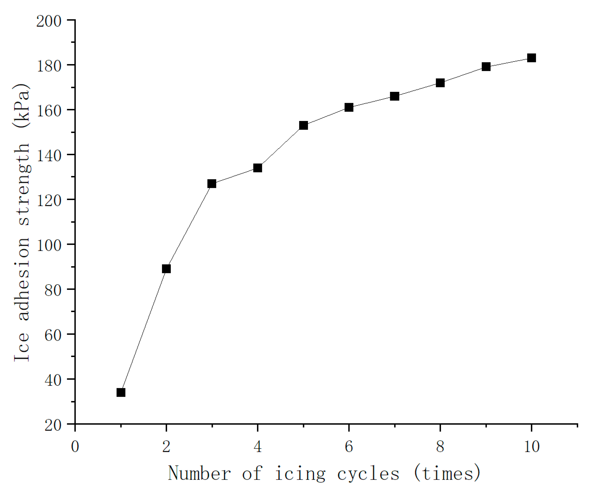
In practical applications, materials are subjected to repeated cycles of freezing and thawing, which can lead to microstructural damage from ice crystal growth. This damage impairs the material’s hydrophobic and anti-icing properties, potentially causing failure. Consequently, understanding the durability of samples during these cycles is of paramount importance. To assess the samples’ adhesive strength under these conditions, multiple tests were conducted following ice adhesion strength measurements. Based on the results presented in Table 5, the circular dot secondary structure with superior ice adhesion strength was selected for cyclic freezing tests. The test results are shown in Figure 11.
The experimental findings demonstrate that the superhydrophobic surface of PMMA effectively reduces the ice adhesion strength. However, a significant increase in ice adhesion was observed during the first four freezing cycles, followed by a gradual rise from the fifth cycle onwards. In comparison to untreated PMMA, the superhydrophobic PMMA surface exhibits a more substantial reduction in ice adhesion.
4. Conclusions
This study employed femtosecond laser ablation to fabricate micro- and nanoscale structures on PMMA, resulting in a surface with enhanced anti-icing properties. Under the action of a femtosecond laser, PMMA undergoes photochemical reactions, primarily involving depolymerization into methyl methacrylate monomers and side-chain cleavage, generating gaseous byproducts. Theoretical calculations determined the beam waist radius to be 46 μm, and the ablation threshold for PMMA was found to be 0.68 joules per square centimeter. A variety of primary (grating, cylindrical, and parallelogram) and secondary (cross, dot, and triangular) microstructures were designed and fabricated. Among these, square pillars and dot-shaped secondary structures exhibited superior hydrophobicity, with contact angles of 142.8° and 153.7°, respectively. Comparative anti-icing tests revealed that superhydrophobic surfaces, compared to untreated PMMA, extended freezing times by approximately 40%, significantly reducing the frost layer thickness, and exhibited an approximately eight-fold improvement in de-icing efficiency. This research contributes to the expansion of PMMA’s application potential in low temperature environments.
Author Contributions
Conceptualization, Y.C.; methodology, A.F. and Y.C.; investigation, A.F. and Y.C.; data curation, Y.C. and A.F.; writing—original draft preparation, A.F. and Y.C.; writing—review and editing, A.F. and Y.C. All authors have read and agreed to the published version of the manuscript.
Funding
This study was supported by the Major Special Project of Wenzhou Science and Technology Innovation and Tackling Industry (ZG2020029), and the Innovation Fund of Wenzhou University Rui’an Graduate College (YC202212001).
Data Availability Statement
Data are contained within the article.
Conflicts of Interest
We declare that we do not have any commercial or associative interest that represents a conflict of interest in connection with the work submitted.
References
- Wang, P.; Yao, T.; Li, Z.; Wei, W.; Xie, Q.; Duan, W.; Han, H. A Superhydrophobic/Electrothermal Synergistically Anti-Icing Strategy Based on Graphene Composite. Compos. Sci. Technol. 2020, 198, 108307. [Google Scholar] [CrossRef]
- Sarshar, M.A.; Song, D.; Swarctz, C.; Lee, J.; Choi, C.-H. Anti-Icing or Deicing: Icephobicities of Superhydrophobic Surfaces with Hierarchical Structures. Langmuir 2018, 34, 13821–13827. [Google Scholar] [CrossRef] [PubMed]
- Kravanja, G.; Godec, R.F.; Rozman, M.; Rudolf, R.; Ivanic, A. Biomimetic Superhydrophobic Concrete with Enhanced Anticorrosive, Freeze Thaw, and Deicing Resistance. Adv. Eng. Mater. 2022, 24, 2101445. [Google Scholar] [CrossRef]
- Boinovich, L.B.; Emelyanenko, A.M.; Ivanov, V.K.; Pashinin, A.S. Durable Icephobic Coating for Stainless Steel. ACS Appl. Mater. Interfaces 2013, 5, 2549–2554. [Google Scholar] [CrossRef]
- Dong, X.; Gao, S.; Huang, J.; Li, S.; Zhu, T.; Cheng, Y.; Zhao, Y.; Chen, Z.; Lai, Y. A Self-Roughened and Biodegradable Superhydrophobic Coating with UV Shielding, Solar-Induced Self-Healing and Versatile Oil–Water Separation Ability. J. Mater. Chem. A 2019, 7, 2122–2128. [Google Scholar] [CrossRef]
- Li, Z.; Wang, X.; Bai, H.; Cao, M. Advances in Bioinspired Superhydrophobic Surfaces Made from Silicones: Fabrication and Application. Polymers 2023, 15, 543. [Google Scholar] [CrossRef]
- Jalil, S.A.; Akram, M.; Bhat, J.A.; Hayes, J.J.; Singh, S.C.; ElKabbash, M.; Guo, C. Creating Superhydrophobic and Antibacterial Surfaces on Gold by Femtosecond Laser Pulses. Appl. Surf. Sci. 2020, 506, 144952. [Google Scholar] [CrossRef] [PubMed]
- Yan, Y.Y.; Gao, N.; Barthlott, W. Mimicking Natural Superhydrophobic Surfaces and Grasping the Wetting Process: A Review on Recent Progress in Preparing Superhydrophobic Surfaces. Adv. Colloid Interface Sci. 2011, 169, 80–105. [Google Scholar] [CrossRef]
- Shen, Y.; Wu, X.; Tao, J.; Zhu, C.; Lai, Y.; Chen, Z. Icephobic Materials: Fundamentals, Performance Evaluation, and Applications. Prog. Mater. Sci. 2019, 103, 509–557. [Google Scholar] [CrossRef]
- Zhang, W.; Liu, F.; Li, Y.; Chen, T.; Nwokolo, I.K.; Ahmed, S.; Han, E. Modified Graphene Micropillar Array Superhydrophobic Coating with Strong Anti-Icing Properties and Corrosion Resistance. Coatings 2024, 14, 247. [Google Scholar] [CrossRef]
- Neinhuis, C. Characterization and Distribution of Water-Repellent, Self-Cleaning Plant Surfaces. Ann. Bot. 1997, 79, 667–677. [Google Scholar] [CrossRef]
- Barthlott, W.; Neinhuis, C. Purity of the Sacred Lotus, or Escape from Contamination in Biological Surfaces. Planta 1997, 202, 1–8. [Google Scholar] [CrossRef]
- Kulinich, S.A.; Farhadi, S.; Nose, K.; Du, X.W. Superhydrophobic Surfaces: Are They Really Ice-Repellent? Langmuir 2011, 27, 25–29. [Google Scholar] [CrossRef] [PubMed]
- Zhou, J.; Zheng, H.; Sheng, W.; Hao, X.; Zhang, X. Preparation and Anti-Icing Properties of Zirconia Superhydrophobic Coating. Molecules 2024, 29, 1837. [Google Scholar] [CrossRef] [PubMed]
- Liu, X.; Zhou, Z.; Chen, M.; Liu, Z.; Jiang, S.; Wang, L. Preparation of Durable Superhydrophobic Coatings Based on Discrete Adhesives. Coatings 2024, 14, 463. [Google Scholar] [CrossRef]
- Huang, W.; Huang, J.; Guo, Z.; Liu, W. Icephobic/Anti-Icing Properties of Superhydrophobic Surfaces. Adv. Colloid Interface Sci. 2022, 304, 102658. [Google Scholar] [CrossRef] [PubMed]
- Song, J.; Li, Y.; Xu, W.; Liu, H.; Lu, Y. Inexpensive and Non-Fluorinated Superhydrophobic Concrete Coating for Anti-Icing and Anti-Corrosion. J. Colloid Interface Sci. 2019, 541, 86–92. [Google Scholar] [CrossRef] [PubMed]
- Cheng, T.; He, R.; Zhang, Q.; Zhan, X.; Chen, F. Magnetic Particle-Based Super-Hydrophobic Coatings with Excellent Anti-Icing and Thermoresponsive Deicing Performance. J. Mater. Chem. A 2015, 3, 21637–21646. [Google Scholar] [CrossRef]
- Xie, H.; Wei, J.; Duan, S.; Zhu, Q.; Yang, Y.; Chen, K.; Zhang, J.; Li, L.; Zhang, J. Non-Fluorinated and Durable Photothermal Superhydrophobic Coatings Based on Attapulgite Nanorods for Efficient Anti-Icing and Deicing. Chem. Eng. J. 2022, 428, 132585. [Google Scholar] [CrossRef]
- Weng, W.; Deng, Q.; Yang, P.; Yin, K. Femtosecond Laser-Chemical Hybrid Processing for Achieving Substrate-Independent Superhydrophobic Surfaces. J. Cent. South Univ. 2024, 31, 1–10. [Google Scholar] [CrossRef]
- Lee, S.-I.; Cheong, H.; Park, J.-W.; Kim, M.; Paik, H. Gloss Control of PMMA/ABS Co-Extrusion Sheet Using Cross-Linked PMMA Particles Br. Polym. Korea 2023, 47, 72–78. [Google Scholar] [CrossRef]
- Suriano, R.; Kuznetsov, A.; Eaton, S.M.; Kiyan, R.; Cerullo, G.; Osellame, R.; Chichkov, B.N.; Levi, M.; Turri, S. Femtosecond Laser Ablation of Polymeric Substrates for the Fabrication of Microfluidic Channels. Appl. Surf. Sci. 2011, 257, 6243–6250. [Google Scholar] [CrossRef]
- Luo, Y.; Jia, W.; Song, Y.; Liu, B.; Hu, M.; Chai, L.; Wang, C. High-Repetition-Rate Femtosecond Laser Micromachining of Poly(Methyl Methacrylate). Chin. Opt. Lett. 2015, 13, 070003. [Google Scholar]
- Will, M.; Nolte, S.; Chichkov, B.N.; Tünnermann, A. Optical Properties of Waveguides Fabricated in Fused Silica by Femtosecond Laser Pulses. Appl. Opt. 2002, 41, 4360. [Google Scholar] [CrossRef] [PubMed]
- Wang, W.; Mei, X.; Jiang, G.; Lei, S.; Yang, C. Effect of Two Typical Focus Positions on Microstructure Shape and Morphology in Femtosecond Laser Multi-Pulse Ablation of Metals. Appl. Surf. Sci. 2008, 255, 2303–2311. [Google Scholar] [CrossRef]
- Szameit, A.; Dreisow, F.; Pertsch, T.; Nolte, S.; Tünnermann, A. Control of Directional Evanescent Coupling in Fs Laser Written Waveguides. Opt. Express 2007, 15, 1579. [Google Scholar] [CrossRef] [PubMed]
- Stenzel, E.; Gogoll, S.; Sils, J.; Huisinga, M.; Johansen, H.; Kästner, G.; Reichling, M.; Matthias, E. Laser Damage of Alkaline-Earth Fluorides at 248 nm and the Influence of Polishing Grades. Appl. Surf. Sci. 1997, 109–110, 162–167. [Google Scholar] [CrossRef]
- Li, F.; Chen, X.; Lin, W.; Pan, H.; Jin, X.; Hua, X. Nanosecond Laser Ablation of Al-Si Coating on Boron Steel. Surf. Coat. Technol. 2017, 319, 129–135. [Google Scholar] [CrossRef]
- Bonse, J.; Wrobel, J.M.; Krüger, J.; Kautek, W. Ultrashort-Pulse Laser Ablation of Indium Phosphide in Air. Appl. Phys. A. 2001, 72, 89–94. [Google Scholar] [CrossRef]
- Lan, L.; Wang, H.; Zhu, L.; Di, Y.; Kang, J.; Qiu, J. Preparation and Wetting Mechanism of Laser-Etched Composite Self-Assembled 1H,1H,2H,2H-Perfluorodecyltriethoxysilane Superhydrophobic Surface Coating. Phys. Status Solidi A 2022, 219, 2100568. [Google Scholar] [CrossRef]
- Zhao, S.; Zhang, S.; Ge, Z.; Li, J.; Xie, J.; Xu, J.; Xie, Z.; Yu, K. Study on Delaying Frost Growth Performanceof Micro-Nanostructure SuperhydrophobicCopper Surfaces. Pol. J. Environ. Stud. 2023, 32, 943–951. [Google Scholar] [CrossRef] [PubMed]
- Ickes, L.; Welti, A.; Hoose, C.; Lohmann, U. Classical Nucleation Theory of Homogeneous Freezing of Water: Thermodynamic and Kinetic Parameters. Phys. Chem. Chem. Phys. 2015, 17, 5514–5537. [Google Scholar] [CrossRef] [PubMed]
Figure 1.
Experimental diagram of ice adhesion strength.
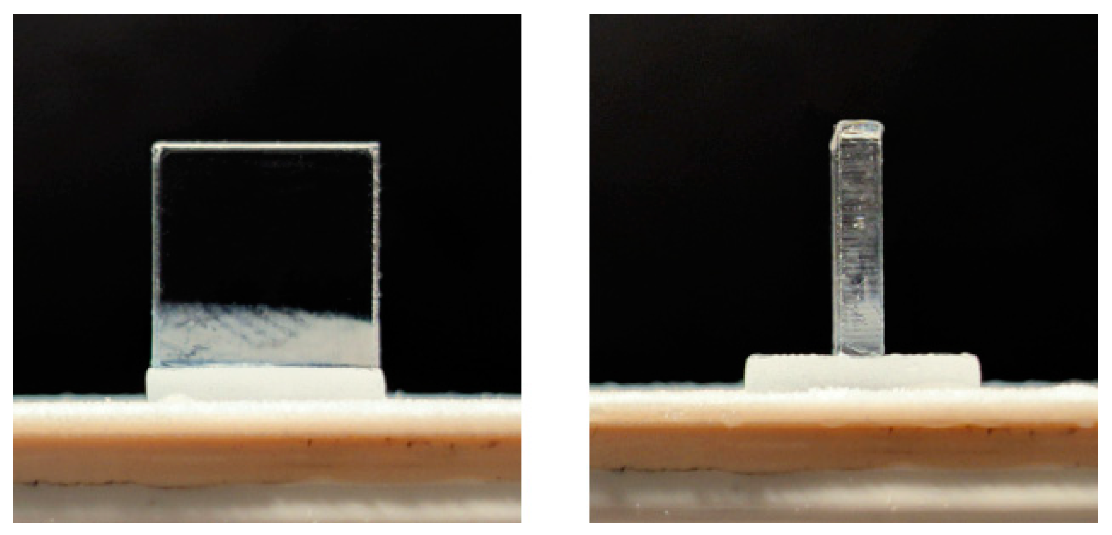
Figure 2.
Results of laser confocal microscopy with average power of 4 W and scanning speed of 1 mm/s.
Figure 2.
Results of laser confocal microscopy with average power of 4 W and scanning speed of 1 mm/s.
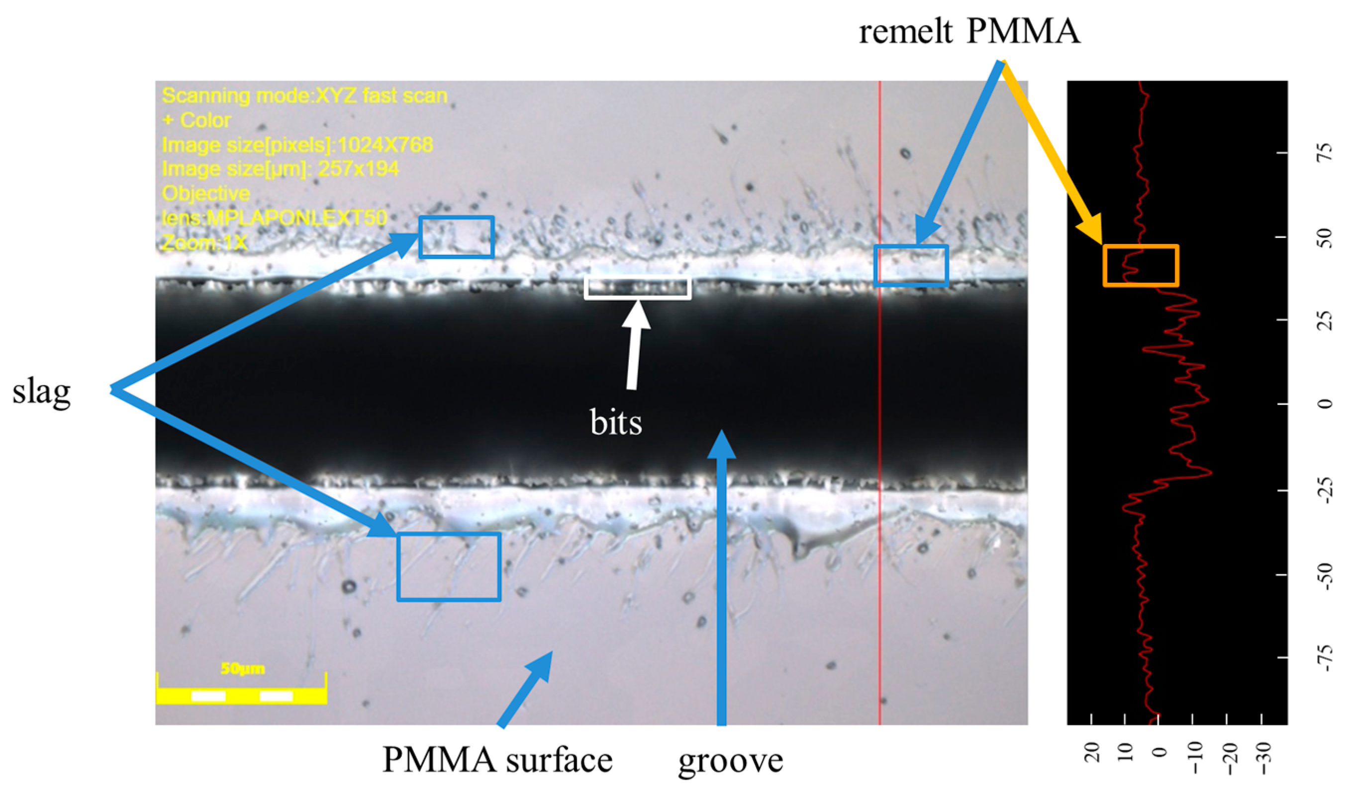
Figure 3.
EDS of PMMA: (a) Detection area; (b) oxygen distribution map; (c) carbon distribution map; (d) energy spectra of the processed area; (e) energy spectra of unprocessed areas.
Figure 3.
EDS of PMMA: (a) Detection area; (b) oxygen distribution map; (c) carbon distribution map; (d) energy spectra of the processed area; (e) energy spectra of unprocessed areas.

Figure 4.
Microstructure design diagrams: (a) Grating structure; (b) cylindrical structure; (c) parallelogram structure; (d) cross-shape secondary structure; (e) dot-shape secondary structure; (f) triangular secondary structure.
Figure 4.
Microstructure design diagrams: (a) Grating structure; (b) cylindrical structure; (c) parallelogram structure; (d) cross-shape secondary structure; (e) dot-shape secondary structure; (f) triangular secondary structure.

Figure 5.
Microscope image at 10× magnification: (a) Grating structure; (b) cylindrical structure; (c) parallelogram structure; (d) cross-shape secondary structure; (e) dot-shape secondary structure; (f) triangular secondary structure.
Figure 5.
Microscope image at 10× magnification: (a) Grating structure; (b) cylindrical structure; (c) parallelogram structure; (d) cross-shape secondary structure; (e) dot-shape secondary structure; (f) triangular secondary structure.

Figure 6.
Representative microstructural morphologies: (a) Grating structure; (b) cylindrical structure; (c) parallelogram structure; (d) cross-shape secondary structure; (e) dot-shape secondary structure; (f) triangular secondary structure.
Figure 6.
Representative microstructural morphologies: (a) Grating structure; (b) cylindrical structure; (c) parallelogram structure; (d) cross-shape secondary structure; (e) dot-shape secondary structure; (f) triangular secondary structure.
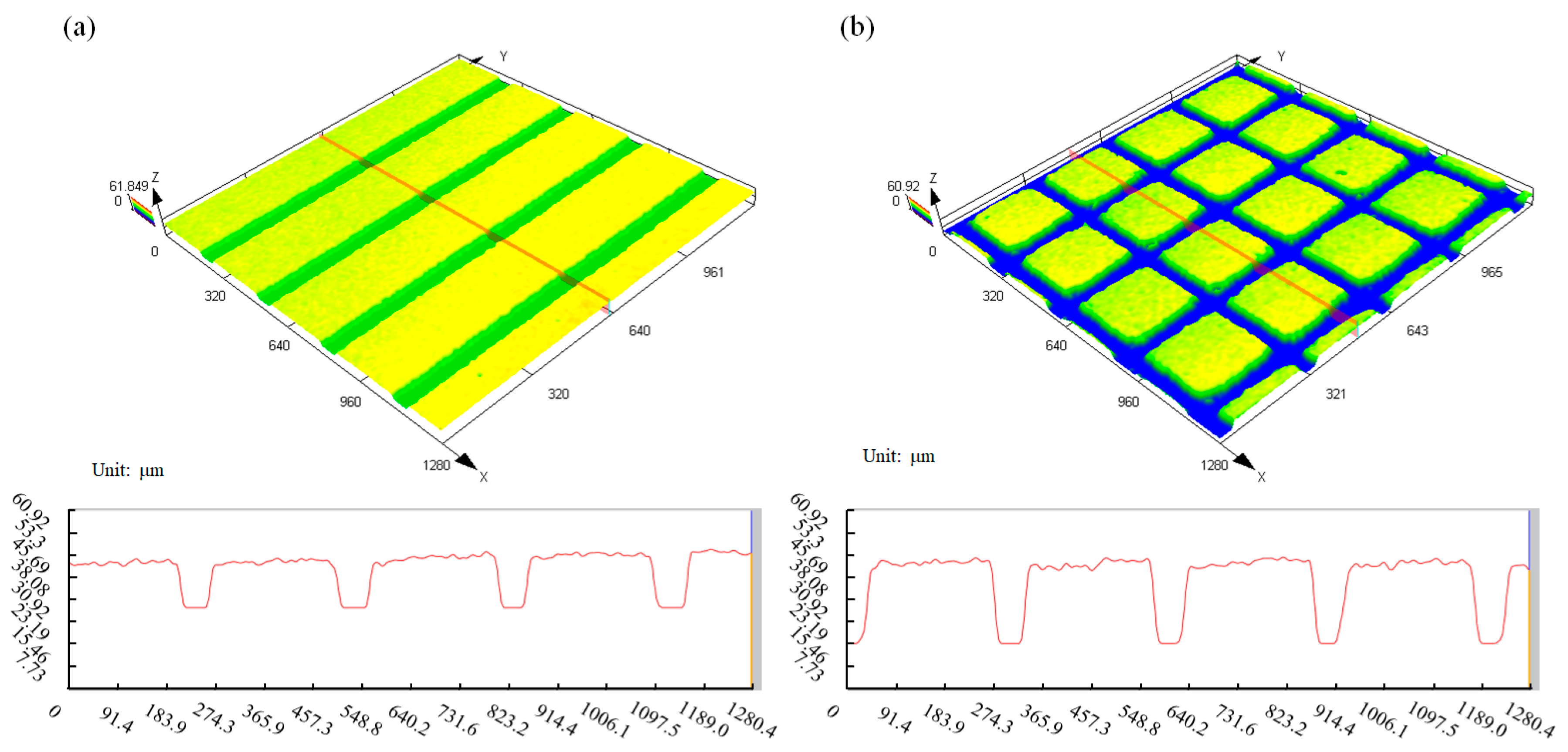
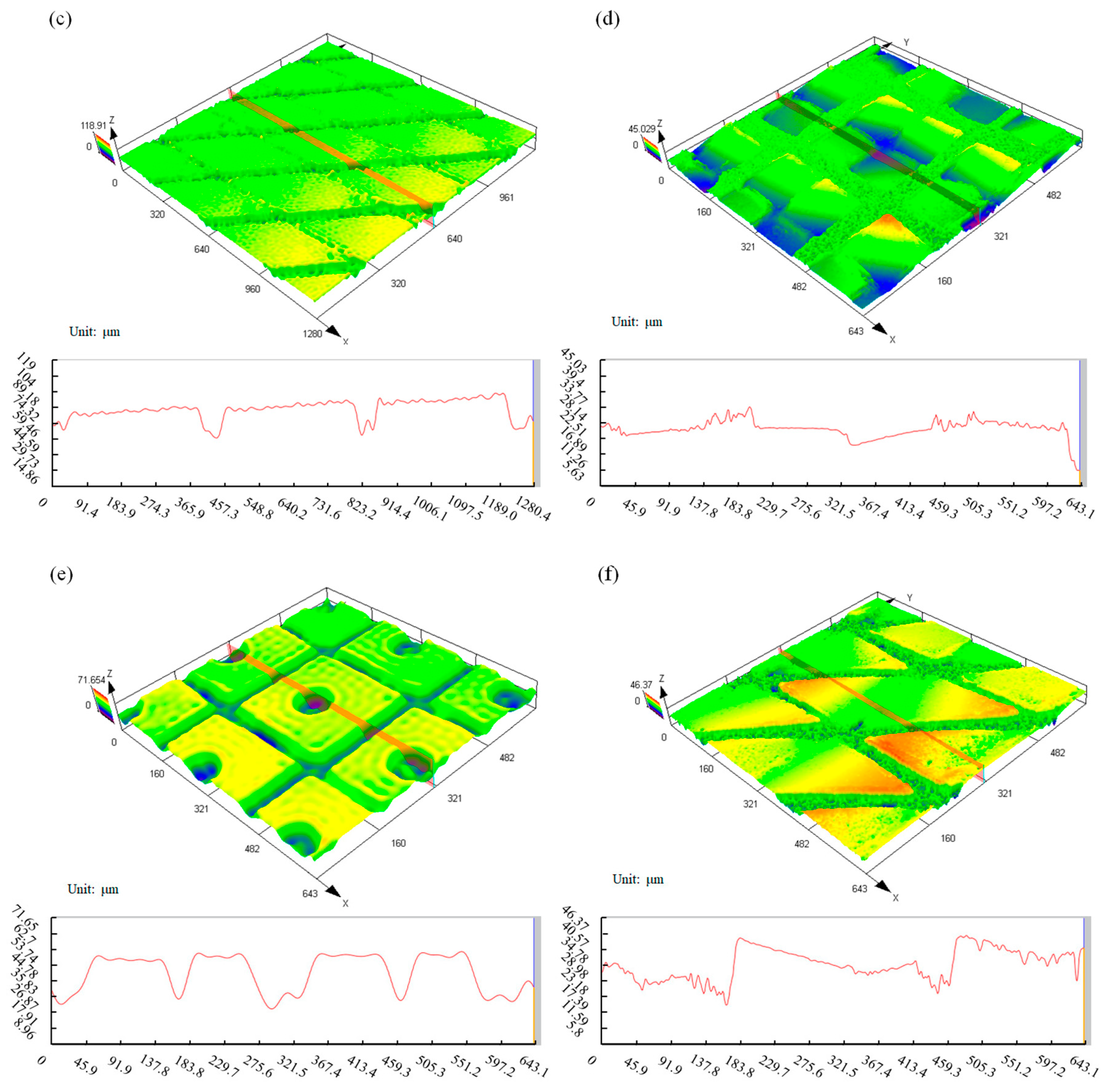
Figure 7.
PMMA surface SEM: (a) Polished surface; (b) fluorinated surfaces; (c) enlarged view of the fluorinated surface.
Figure 7.
PMMA surface SEM: (a) Polished surface; (b) fluorinated surfaces; (c) enlarged view of the fluorinated surface.
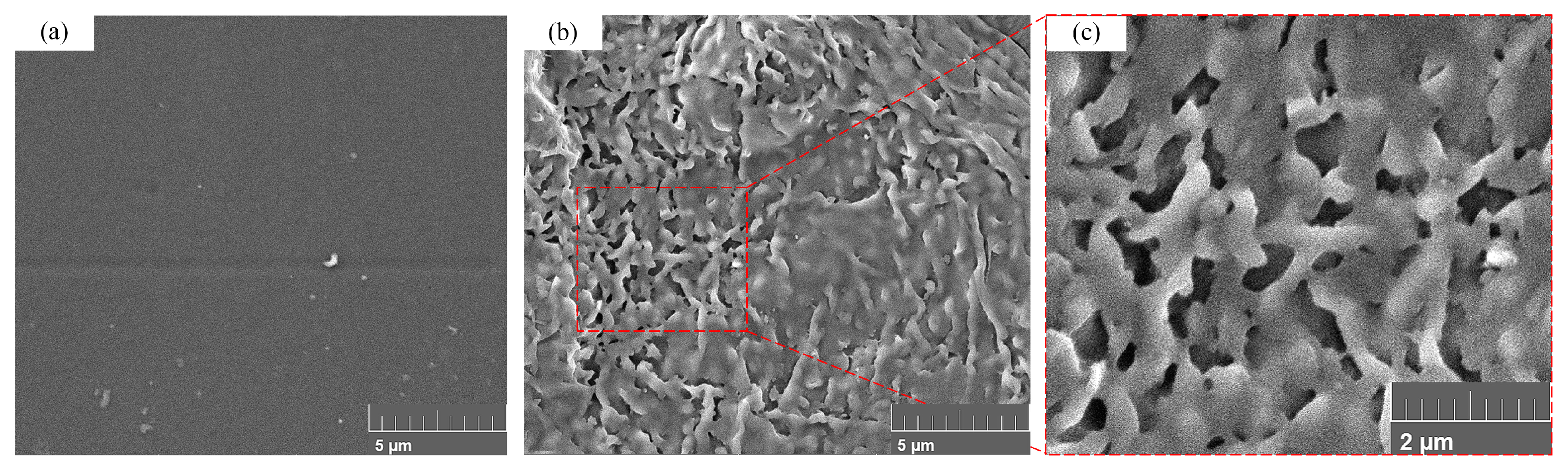
Figure 8.
A set of contact angle measurement: (a) Grating structure; (b) cylindrical structure; (c) parallelogram structure; (d) cross-shape secondary structure; (e) dot-shape secondary structure; (f) triangular secondary structure.
Figure 8.
A set of contact angle measurement: (a) Grating structure; (b) cylindrical structure; (c) parallelogram structure; (d) cross-shape secondary structure; (e) dot-shape secondary structure; (f) triangular secondary structure.

Figure 9.
Surface freezing experiment procedure: (Left) PMMA, (Right) dot-shape secondary structure.
Figure 9.
Surface freezing experiment procedure: (Left) PMMA, (Right) dot-shape secondary structure.

Figure 10.
(Left) Experimental process of PMMA frost protection, (Right) PMMA dot-shape secondary structure.
Figure 10.
(Left) Experimental process of PMMA frost protection, (Right) PMMA dot-shape secondary structure.
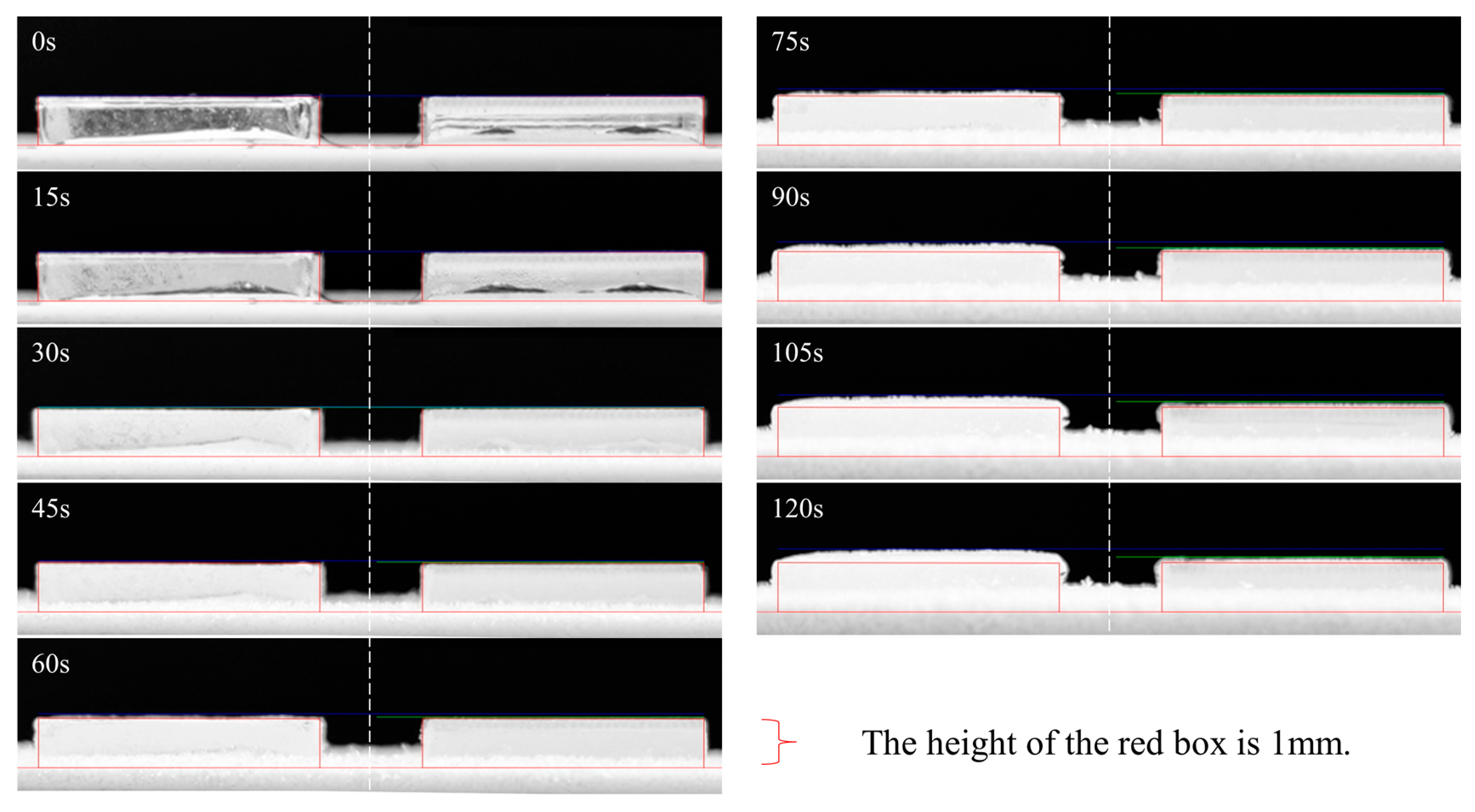
Figure 11.
Relationship between ice adhesion strength and number of freezing cycles.

Table 1.
Laser processing parameter.
| Parameter | Unit | Value |
|---|---|---|
| Impulse Frequency | kHz | 100 |
| Pulse Width | fs | 400 |
| Wave Length | nm | 1030 |
| Average Power | W | 4 |
| Scanning Speed | mm/s | 1 |
Table 2.
Contact Angle Measurement.
| Number | Microstructure | Average Contact Angle (°) |
|---|---|---|
| 1 | Grating Structure | 132.3 ± 2 |
| 2 | Cylindrical Structure | 142.5 ± 0.6 |
| 3 | Parallelogram Structure | 137.8 ± 0.6 |
| 4 | Cross-Shape Secondary Structure | 149.9 ± 1.1 |
| 5 | Dot-Shape Secondary Structure | 153.6 ± 0.6 |
| 6 | Triangular Secondary Structure | 151.9 ± 0.5 |
| 7 | PMMA | 132.3 ± 2 |
Table 3.
Experimental Results for Freezing Time of Hydrophobic Surfaces.
| Number | Microstructure | Freezing Time (s) |
|---|---|---|
| 1 | Grating Structure | 198 |
| 2 | Cylindrical Structure | 243 |
| 3 | Parallelogram Structure | 233 |
| 4 | Cross-Shape Secondary Structure | 265 |
| 5 | Dot-Shape Secondary Structure | 276 |
| 6 | Triangular Secondary Structure | 269 |
| 7 | PMMA | 193 |
Table 4.
Frost Layer Growth Thickness within 2 min.
| Number | Microstructure | Frost Layer Thickness (mm) |
|---|---|---|
| 1 | Grating Structure | 0.27 |
| 2 | Cylindrical Structure | 0.18 |
| 3 | Parallelogram Structure | 0.19 |
| 4 | Cross-Shape Secondary Structure | 0.12 |
| 5 | Dot-Shape Secondary Structure | 0.11 |
| 6 | Triangular Secondary Structure | 0.12 |
| 7 | PMMA | 0.30 |
Table 5.
Adhesion Strength Test for Ice.
| Number | Microstructure | Adhesion Strength of Ice (kPa) |
|---|---|---|
| 1 | Grating Structure | 232.2 ± 2.1 |
| 2 | Cylindrical Structure | 100.9 ± 0.3 |
| 3 | Parallelogram Structure | 155.6 ± 3.3 |
| 4 | Cross-Shape Secondary Structure | 66.4 ± 0.9 |
| 5 | Dot-Shape Secondary Structure | 33.7 ± 0.9 |
| 6 | Triangular Secondary Structure | 52.4 ± 0.4 |
| 7 | PMMA | 308.1 ± 3.5 |
Disclaimer/Publisher’s Note: The statements, opinions and data contained in all publications are solely those of the individual author(s) and contributor(s) and not of MDPI and/or the editor(s). MDPI and/or the editor(s) disclaim responsibility for any injury to people or property resulting from any ideas, methods, instructions or products referred to in the content. |
© 2024 by the authors. Licensee MDPI, Basel, Switzerland. This article is an open access article distributed under the terms and conditions of the Creative Commons Attribution (CC BY) license (https://creativecommons.org/licenses/by/4.0/).
Share and Cite
MDPI and ACS Style
Chen, Y.; Feng, A. Anti-Ice PMMA Surface Design and Processing. Processes 2024, 12, 1322. https://doi.org/10.3390/pr12071322
AMA Style
Chen Y, Feng A. Anti-Ice PMMA Surface Design and Processing. Processes. 2024; 12(7):1322. https://doi.org/10.3390/pr12071322
Chicago/Turabian StyleChen, Yanming, and Aixin Feng. 2024. "Anti-Ice PMMA Surface Design and Processing" Processes 12, no. 7: 1322. https://doi.org/10.3390/pr12071322
Note that from the first issue of 2016, this journal uses article numbers instead of page numbers. See further details here.