Article

Experimental Investigation on Active Heat Transfer Improvement in Double-Pipe Heat Exchangers

1
Department of Mechanical Engineering, Payame Noor University (PNU), Tehran 193953697, Iran
2
Department of Mechanical Engineering, Faculty of Engineering, University of Bojnord, Bojnord 9453155111, Iran
*
Authors to whom correspondence should be addressed.
Processes 2024, 12(7), 1333; https://doi.org/10.3390/pr12071333
Submission received: 28 May 2024 / Revised: 17 June 2024 / Accepted: 22 June 2024 / Published: 27 June 2024
(This article belongs to the Section Chemical Processes and Systems)

Abstract

:
In this research, the effect of ultrasonic waves (UWs) on the heat transfer rate of a water-to-water double-pipe heat exchanger (DPHX) was investigated. To conduct the experiments, four ultrasonic transducers with similar sound frequencies of 40 kHz and a maximum power of 60 W were utilized. All the transducers were placed on the outer shell of the DPHX. The effects of the hot water flow rate and the temperature level of the hot water inlet, ranging from 40 to 60 °C in the central pipe, both in the absence and presence of UWs, were measured under UWs at different powers from 0 to 240 W. The performed experiments show that UWs increase the heat transfer rate, while the highest heat transfer rate improvement of 104% occurs at an inlet temperature of 60 °C and ultrasonic power level of 240 W. Given the scarcity of information regarding heat transfer behavior in ultrasonic-assisted DPHXs, these findings could illuminate the path for designing such heat exchangers.

1. Introduction

Given the increasing energy consumption worldwide and the limited availability of fossil fuel resources, coupled with environmental concerns, the importance of implementing new methods to prevent energy losses is paramount for future generations. A significant portion of energy consumption results from inefficient equipment, making solutions for improving heat transfer and increasing efficiency in the industry highly important. To enhance heat transfer, solutions primarily focus on increasing the heat transfer coefficient and can be categorized as active and passive techniques [1]. Active techniques involve applying external forces to the heat exchanger (HX) or fluid, such as plate vibration, acoustic waves, or electrical fields, to increase the heat transfer coefficient. Passive techniques, on the other hand, utilize special geometries of the HX or additives, such as nano-fluids and fins, to enhance heat transfer. Numerous studies have been conducted on increasing fluid heat transfer in HXs using these techniques.
Ultrasonic-assisted heat transfer enhancement methods offer a compelling combination of high efficiency, versatility, and scalability, positioning them favorably compared with other active and passive techniques. While they involve higher costs and complexity, their effectiveness in enhancing heat transfer, particularly in challenging applications, often justifies the investment. In contrast, passive methods provide simpler, more cost-effective solutions but with moderate enhancement levels. Ultimately, the choice of method depends on the specific requirements and constraints of the application at hand. Ultrasonic technology’s application spans various domains, including but not limited to drying [2,3], cooling [4,5], welding [6,7], fouling and cleaning [8,9], and also chemical intensifying [10,11]. Despite its widespread use, detailed examinations of the influence of ultrasound on convective heat transfer phenomena remain scant, with diverse theories proposed in earlier studies. This study specifically investigates the active heat transfer improvement (HTI) method of using ultrasonic waves (UWs). One of the pioneering studies that investigated the influence of acoustic fields on enhancing heat transfer was conducted by Li and Parker [12]. They reported an increase in convective heat transfer by utilizing UW effects. In 1965, Bergles [13] conducted an experimental study to determine the effect of high-intensity UWs on heat transfer rates to water flowing through a central pipe. The study revealed that the fluid conditions and cavitation effects had a significant influence on the level of HTI. The maximum increase in the local heat transfer coefficient was found to be 40% under low flow rate conditions. Kim et al. [14] carried out an investigation, exploring how UWs influence the transfer of heat from a platinum wire to both water and ethanol. Based on their findings, the use of UWs generated by an ultrasonic transducer led to a notable improvement in the free convection heat transfer coefficient. They conducted experiments using various power levels and a frequency of 20.6 kHz, which resulted in an impressive eight-fold growth in the convective heat transfer coefficient. Loh et al. [15] conducted a study that combined numerical simulations and practical experiments to investigate the augmentation of heat transfer through UWs. Their analysis unveiled correlations among the speed of sound, the amplitude of vibration, and the wavelength of the excited surface. Moreover, Setareh et al. [16] explored the HTI in a double-pipe heat exchanger (DPHX) with the application of UWs. The effects of ultrasonic excitation, specifically with a 120 W ultrasonic power, on the flow of hot and cold fluids, as well as the associated pressure drop, were investigated. The numerical findings indicated that the crossflows induced by the propagation of UWs through the cold fluid amplify heat transfer. Komarov and Hirasawa [17] experimentally studied the increase in gas-phase heat transfer in the presence of a sound field using pt wires. The findings indicated that the effect of sound waves decreases with growth in gas flow velocity. Monnot et al. [18] conducted experimental tests to study the impacts of ultrasound vibrations on heat transfer in an ultrasonic reactor. The reactor was equipped with an ultrasonic transducer located at the bottom of the vessel. The study aimed to assess the impact of variable frequency capability on heat transfer within the system. The findings of the study revealed that the utilization of ultrasound waves resulted in a significant enhancement in the cooling rate of the reactor. This improvement was attributed to the increase in the overall heat transfer coefficient of its coil, which led to a remarkable increase of up to 100% in cooling efficiency. The investigation conducted by Gondrexon et al. [19] studied the thermal behavior of a shell-and-tube HX when subjected to low-frequency ultrasound. Their findings indicated a notable augmentation in the heat transfer efficiency of the system, with emphasis placed on enhancements predominantly observed within the shell component. Furthermore, Legay et al. [20] designed and tested a vibrating DPHX. They reported that ultrasound vibrations reduce the convective thermal resistance and enhance the thermal performance of the HX. In another investigation, Legay et al. [21] conducted a study where they compared the performance of a shell-and-tube HX with that of a vibrating DPHX under the influence of ultrasound waves. The findings indicated that the shell-and-tube HX exhibited better operational efficiency in comparison with the alternative system. Amiri Delouei et al. [22] conducted experiments to investigate the impact of UWs on HTI in louvered fin-and-tube HXs. This investigation considered the impacts of different parameters of fluid flow and UWs. The results revealed a positive effect of UWs on HTI in these types of HXs. Furthermore, Amiri Delouei et al. [23,24] investigated the impact of UWs on heat transfer in CPU water-cooling systems. They examined the influences of ultrasonic transducer locations on HTI in CPU water-cooling systems [24]. The results showed minor effects of transducer locations on the cooling system’s efficiency. Hedeshi et al. [25] studied the influence of UWs on nanofluid flow in DPHXs. Their study focused more on the influence of UWs on nanoparticle movement and resulting HTI. Although they reported higher heat transfer rates in the presence of UWs, they did not perform an energy balance to account for existing heat losses. Also, some works focused on the optimization of HXs with active HTI mechanisms [26,27]. Furthermore, an experimental investigation on a small pipe was conducted by Dhanalakshmi et al. [28], investigating the effect of ultrasound vibration on heat transfer rate. The findings indicated that the effect of ultrasound vibrations decreases with increasing flow velocity. In general, most studies on the impacts of ultrasound vibrations on heat transfer have been conducted at low frequencies and often report a positive effect on heat transfer. Also, it is noteworthy that results for heat transfer enhancement in the presence of ultrasonic vibration exhibit significant scatter, even for the same geometry of heat exchangers. This variability is highlighted in the review paper by Legay et al. [29], which demonstrates heat transfer enhancement ranging from insignificant values to increases of up to tenfold. This wide range underscores the challenges in establishing a consistent empirical framework for ultrasonic-assisted heat transfer enhancement.
In this study, an experimental analysis was conducted to investigate the effect of UWs on HTI in a water–water DPHX. The precision of the obtained data was examined through energy balance analysis and validation using existing empirical equations. Experimental tests were conducted under various fluid flow thermophysical conditions and UW specifications. The results demonstrated that the heat transfer rate doubled in certain situations.

2. Experimental Setup

In this experimental investigation, the DPHX and other pertinent apparatus are employed as follows: (1) Hot Water Unit: This unit comprises a cylindrical metal tank capable of holding 10 L of water. It includes a 1500 W electric heater integrated with a thermostat, which maintains the water at a specified temperature; (2) Thermostat: A device used to control and maintain the temperature within the hot water tank; (3) Centrifugal Hot Water Pump: a water pump (Lucky Pro-MKP60-1, Ningbo Time Machinery Industrial Co., Ningbo, China), with a peak flow rate of 40 LPM, facilitates the circulation of hot water within the system; (4) Cold Water Unit: It features an inlet with a consistent temperature for the water, serving as the cooling medium in the heat exchanger; (5) DPHX: The central pipe of this exchanger is fabricated from stainless steel with a thickness of 1 mm and an external diameter of 20 mm. The encompassing pipe is similarly constructed from stainless steel, with a 4 mm thickness, an internal diameter of 80 mm, and an effective length of 1200 mm. The outer pipe is completely insulated with an appropriate thickness of polyurethane; (6) Temperature Sensors: Type K thermocouples are positioned at four locations to measure the inlet and outlet temperatures of both the hot and cold water; (7) Data Logger: A data logger (TM947-SD. Lutron Electronic Enterprise Co., Taiwan) with four channels is used to monitor and display the temperatures at the aforementioned four points; (8) Flow Meter: To measure the flow rates of both hot and cold water, flow meter (NT3, Nixon Flowmeters LTD Co., Cheltenham, UK), with an accuracy of ±5%, is utilized; (9) Flow Control Valves: Four valves are employed to modulate the flow rates of the hot- and cold-water streams; (10) Piezoelectric Transducers: Four 40 kHz, 60 W transducers (Series I, Hesentec Ultrasonic Co., ShenZhen, China) are installed at 25 cm intervals on the outer pipe of the heat exchanger. The installation on the curved pipe surface required a specially designed steel interface piece, featuring a curved surface to match the pipe and a flat surface for the transducer, ensuring efficient ultrasonic vibration transmission to the heat exchanger; (11) Ultrasonic Generator: This device (Hesentec Ultrasonic Co., ShenZhen, China) is used to power the piezoelectric transducers, enabling them to function effectively within the system. Figure 1 depicts the experimental arrangement that was built and utilized in the course of this investigation. Also, Figure 2 displays the schematic of the investigational system.

3. Governing Equations

In this section, the important parameters of the experiments are discussed. The transfer of thermal energy from hot water to cold water is quantified as Qhot, and the amount of heat received by the cold water is denoted by Qcold. Moreover, m ˙ h and m ˙ c represent the volumetric flow rates related to the hot and cold fluids, respectively [30]:
Q hot = m ˙ h C p , h   ( T h , in T h , out )
Q cold = m ˙ c C p , c   ( T c , out T c , in )
T c , in , and T c , out refer to the inlet and outlet temperatures of the cold fluid, while T h , in , and T h , out denote temperature measurements at both the inlet and outlet of the hot fluid. The variables Cp,h, and Cp,c represent the hot and cold fluids’ specific heat capacities, respectively. To determine the specific heat of each fluid, the average temperature between the inlet and outlet situations is considered. It is important to note that in all experiments, after thorough examination and validation, it was established that Qcold ≈ Qhot. However, due to partial losses and heat dissipation, there exists a slight disparity between these two values. Hence, the average heat transfer was employed in calculations, resulting in an error percentage of less than 2% when compared with the values of Qcold and Qhot:
Q avg = Q hot +   Q cold 2
To reach the logarithmic mean temperature difference ( Δ T LMTD ) for counterflow, the following equation is used [31,32]:
Δ T LMTD = ( T h , in T c , out ) ( T h , out     T c , in   ) ln ( T h , in   T c , out T h , out T c , in )
Furthermore, the overall heat transfer coefficient ho for each test is obtained as follows [33,34]:
h o = Q avg A × Δ T LMTD
The inner pipe of the HX has a diameter of 18 mm and an effective length of 1200 mm. A represents the heat transfer area. To investigation the influence of UWs on the heat transfer coefficient, a parameter known as the HTI coefficient ( E v ) was introduced and computed. In Equation (6), ho,us represents the heat transfer coefficient obtained from the application of ultrasound waves through the use of piezoelectric elements, while ho,si is related to the condition where no vibration exists (silence situation):
E v = h o , us h o , si
Also, the two dimensionless numbers of the Reynolds number (Re) and Nusselt number (Nu) are considered based on the subsequent relations:
R e = ρ V D μ
N u = h D k
where ρ , V , D , μ , h , and k indicate the density, velocity, hydraulic diameter, viscosity, convective coefficient, and conductivity coefficient, respectively. These parameters are different for cold and hot fluid flows in the HX. To determine the physical properties of the cold and hot fluids, the bulk temperature criterion is used, which is the average temperature of the inlet and outlet of the HX. The hydraulic diameter is considered the characteristic length in Equations (9) and (10). Consequently, the obtained Reynolds number for the coolant flow ranges from 650 to 700, indicating laminar flow, while, for the hot water flow, it ranges from 3000 to 10,500, indicating turbulent flow. It is worth noting that the uncertainty analysis, based on the method introduced by Moffat [35], indicates that the uncertainty value is less than ±4.6 for all variables.

4. Ultrasonic Enhancement of Heat Transfer Mechanisms

The enhancement of heat transfer in a DPHX through the application of UWs involves multiple interrelated physical mechanisms that operate at both macroscopic and microscopic levels. Understanding these mechanisms is crucial for optimizing the design and operation of ultrasonic-assisted HXs. The key mechanisms are detailed below.

4.1. Macroscopic Effects

At the macroscopic level, UWs influence the overall fluid dynamics and heat transfer characteristics in the HX through several key mechanisms. Acoustic streaming [36,37], a steady, non-oscillatory flow generated by the absorption of high-frequency sound waves, creates pressure gradients and viscous stresses within the fluid, inducing secondary flow patterns. This streaming enhances convective heat transfer by continuously disrupting the thermal boundary layer, leading to an increased overall heat transfer coefficient. Cavitation [38] involves the formation, growth, and collapse of microscopic bubbles in a liquid subjected to UWs. The collapse of these bubbles near heat transfer surfaces produces localized high-velocity micro-jets and shock waves, which disrupt the boundary layer and create intense localized mixing. This action significantly enhances heat transfer rates and increases the surface area available for heat exchange by removing surface fouling. Micro-convection [39], characterized by small-scale fluid movements induced by the oscillatory motion of particles and bubbles within the fluid, also plays a role. UWs cause these particles and bubbles to oscillate, generating vortices and eddies at the microscopic level. These micro-convective currents enhance mixing within the fluid and disrupt the thermal boundary layer, resulting in improved heat transfer efficiency. Thermoacoustic effects [40], arising from interactions between temperature fields and sound waves, induce temperature gradients through compression and rarefaction cycles. These temperature fluctuations contribute to enhanced thermal diffusion, which improves the heat transfer characteristics within the HX.

4.2. Microscopic Effects

At the microscopic level, UWs affect the heat transfer process by altering the behavior of fluid molecules and particles near the heat transfer surfaces. UWs continuously disturb the thermal boundary layer [41], reducing its thickness and promoting higher heat flux. The oscillatory motion and acoustic streaming create a constantly renewing interface between the HX surface and the bulk fluid, minimizing thermal resistance. The agitation caused by UWs can enhance the effective thermal conductivity [42] of the fluid. Increased energy transfer between fluid molecules, due to oscillation and collision under ultrasonic influence, enhances thermal conductivity and heat transfer. Furthermore, cavitation and the resultant micro-jets play a crucial role in removing fouling and scaling from heat transfer surfaces [43]. The intense localized forces generated by bubble collapse clean the surfaces, lowering thermal resistance and increasing heat transfer coefficients.
So, in addition to enhancing heat transfer, ultrasonic vibration technology offers economic benefits such as anti-fouling and anti-agglomeration effects, which reduce maintenance and repair needs for industrial HXs, especially when using nanofluids. Although currently expensive, the cost of ultrasonic technology is expected to decrease with wider adoption.

5. Results and Discussion

This section focuses on a comprehensive investigation into the influence of UWs on a DPHX. To assess the impact of ultrasound waves on heat transfer, a series of experiments was conducted using UWs with a frequency of 40 kHz and with power levels ranging from 48 to 240 W. The effects of these waves are visually presented through graphs, which are illustrated in the subsequent figures. To begin with, the accuracy of the experimental equipment is examined by conducting energy balance analyses.

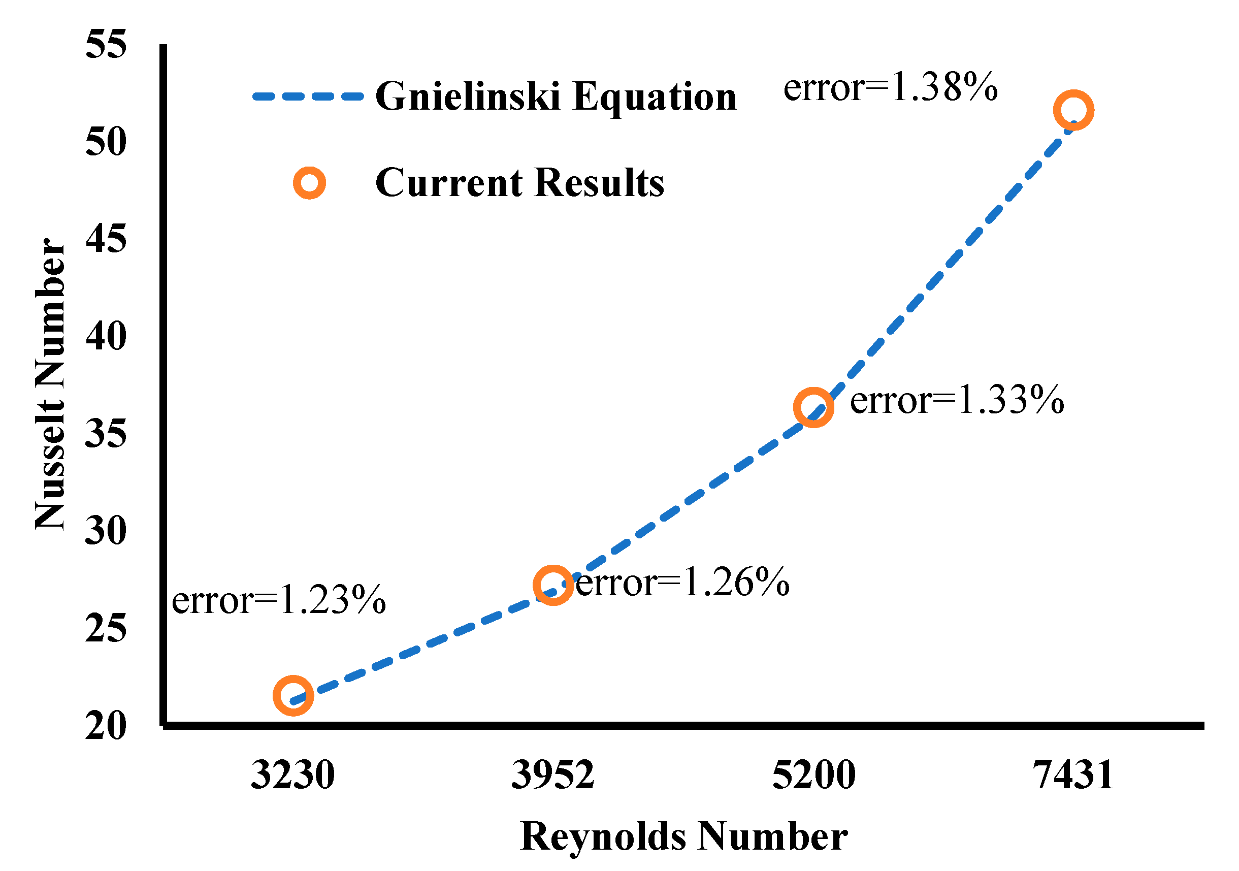
5.1. Validation Tests

The energy balance of the current thermal system is as follows:
Qloss − PUS = Qh − Qc
The parameter PUS represents the power of applied UWs, while Qloss denotes the heat losses to the environment.
Table 1 delineates the experimental data obtained under non-vibrating conditions and with the application of ultrasound waves (UWs). The experiments were performed with an initial cold flow temperature of 19.9 °C and a hot flow temperature of 50 °C. The volumetric flow rates for the cold and hot fluids were 0.04545 L/s and 0.07143 L/s, respectively. Under conditions devoid of ultrasound waves, the hot fluid’s exit temperature was recorded at 45.6 °C, while the cold fluid’s exit temperature equilibrated to 26.7 °C. The calculated thermal loss in this state was 10 W. Conversely, the application of 40 kHz ultrasound waves at a power of 240 W resulted in an increase in these losses to 19 W. Consequently, the exit temperature of the cold water increased to 28.7 °C, and the hot water’s exit temperature slightly decreased to 45.1 °C under the influence of ultrasound. Referencing Table 1, it is evident that the error associated with the use of Equation (9) is minimal, signifying that the experimental results are within an acceptable error margin. It should be noted that the precision of the findings is greatly influenced by properly accounting for energy balancing [44,45].
As another validation test, the results of the current experiment are compared with those of the empirical equation presented by Gnielinski [46] (Figure 3). Gnielinski’s empirical correlation [46] is a prominent equation in heat transfer engineering, utilized to predict the convective heat transfer coefficient for fluid flow within pipes. This correlation is especially effective for calculating the Nusselt number. Its precision and practical applicability have led to its extensive adoption in the field. The Gnielinski equation [46] could be written as follows:
N u = ( 0.125 f ) ( R e 1000 ) P r 1 + 12.7 ( 0.125 f ) 0.5 ( P r 0.66 1 )
In Equation (10), the friction coefficient, f, is achieved as follows [47]:
f = 1 / ( 0.79 ln R e 1.64 ) 2  
Referring to Figure 3, the experimental results demonstrate a strong concordance with Gnielinski’s empirical correlation [46]. The observed maximum deviation from Gnielinski’s empirical correlation [46] is 1.38%, which falls within an acceptable range for experimental research.

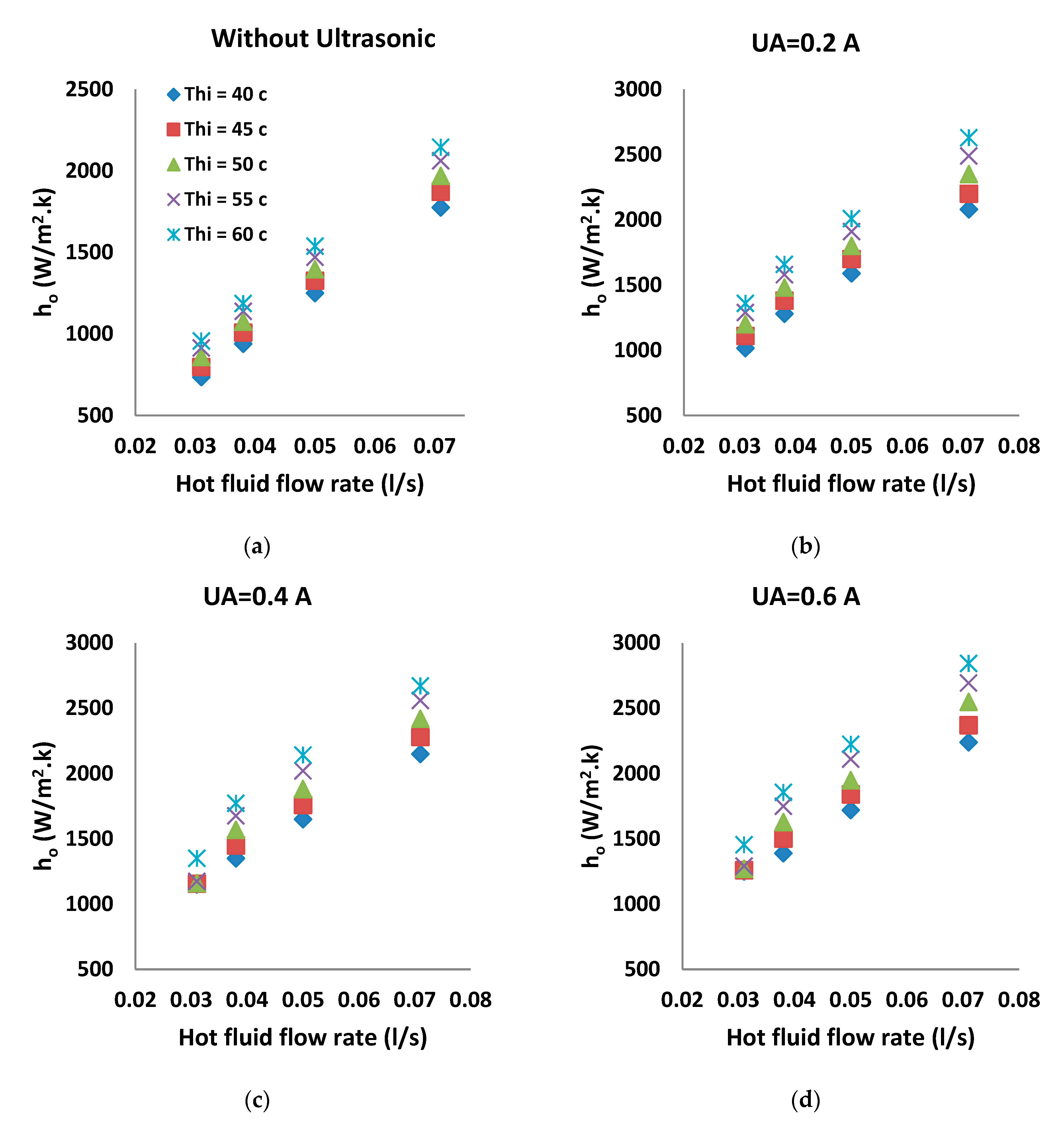
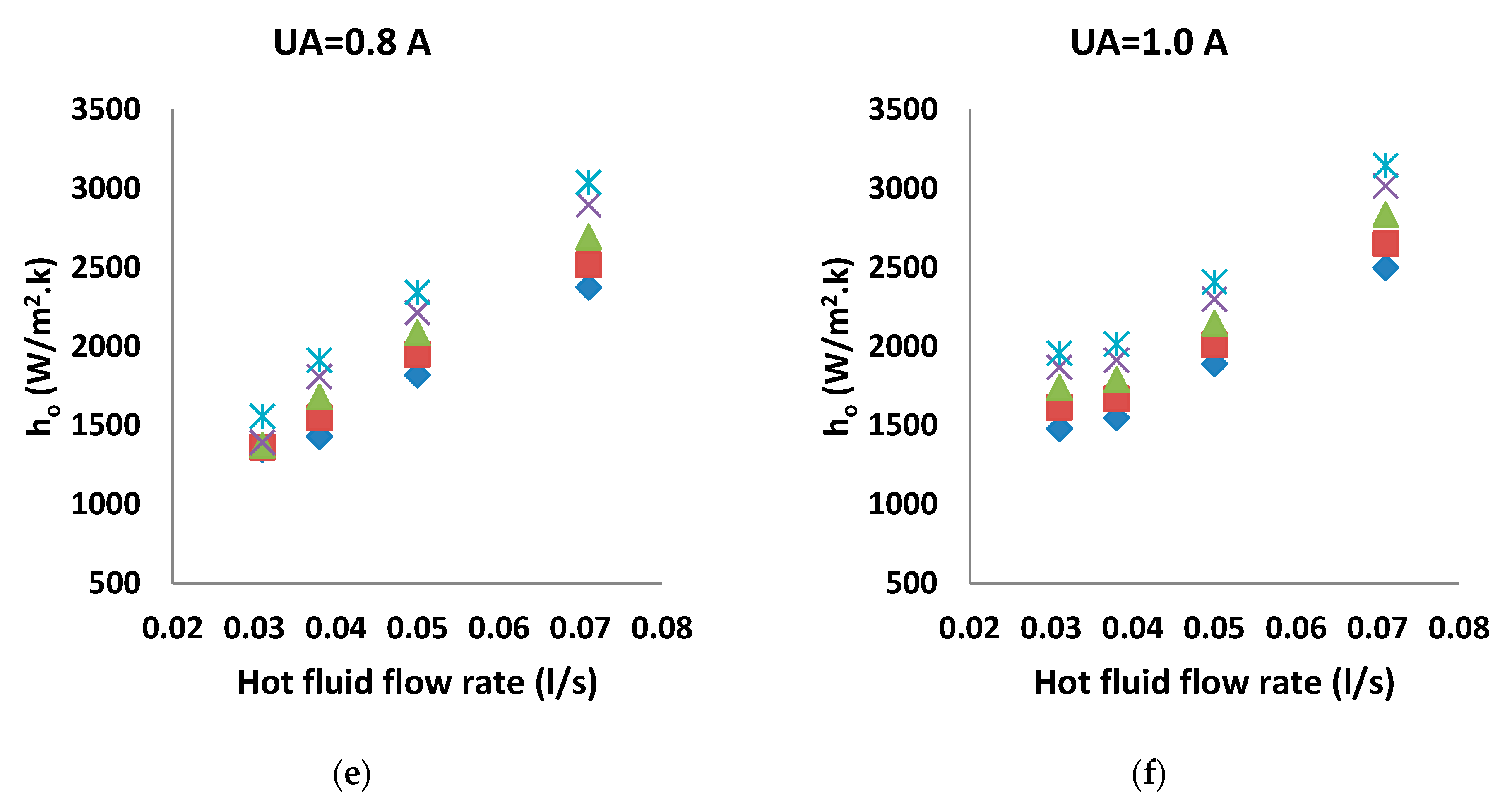
5.2. Variation of Convective Heat Transfer Coefficient

Figure 4a depicts the variations in the heat transfer coefficient as a function of different flow rates of the hot fluid in the absence of UWs. The graph reveals that, as the hot flow rate increases and the flow transitions into a more turbulent state, the heat transfer coefficient experiences an upward trend.
The influence of increasing the power of UWs, which corresponds to a change in ultrasonic amplitude (UA) from 0.2 A to 1 A, is examined in Figure 4b–f. It was determined that augmenting the power of ultrasound waves enhances the heat transfer coefficient, with a more pronounced effect observed at higher power levels. In addition to the role of increased flow rate in inducing turbulence, UWs also contribute to reducing the thermal boundary layer.
Figure 4b showcases the impact of applying UWs with a power level of 48 W. It demonstrates that these waves enhance the convection coefficient, reaching its maximum value at a flow rate of 0.071 L/s. For hot water at a temperature of 60 °C, the convection coefficient increases from 2145 W/m2K to 2630 W/m2K. In other words, there is an improvement of 22.6% in the convection coefficient of the hot water. Furthermore, at the lowest flow rate and the same temperature of 60 °C, the coefficient increases from 958 W/m2K without UWs to 1360 W/m2K when UWs are applied, indicating a significant improvement of 42% in the convection coefficient. As another example, at an ultrasonic amplitude of 0.6 A (Figure 4d), equivalent to a power level of 144 W, with a hot water temperature of 60 °C and a flow rate of 0.031 L/s, the convection coefficient increases from 958 W/m2K without UWs to 1445 W/m2K. This implies that the convection coefficient experiences a significant improvement of 50.8% with the application of UWs with a power level of 144 W. Similarly, under the same experimental conditions but with an applied power of 240 W (Figure 4f) and a flow rate of 0.031 L/s, the convection coefficient further increases to 1960 W/m2K. In other words, it more than doubles compared with the state without UWs. Within the medium where UWs propagate, various phenomena such as acoustic streaming and cavitation occur. These phenomena generate bubbles that disrupt the thermal boundary layer and increase the convection coefficient through their motion and collapse.

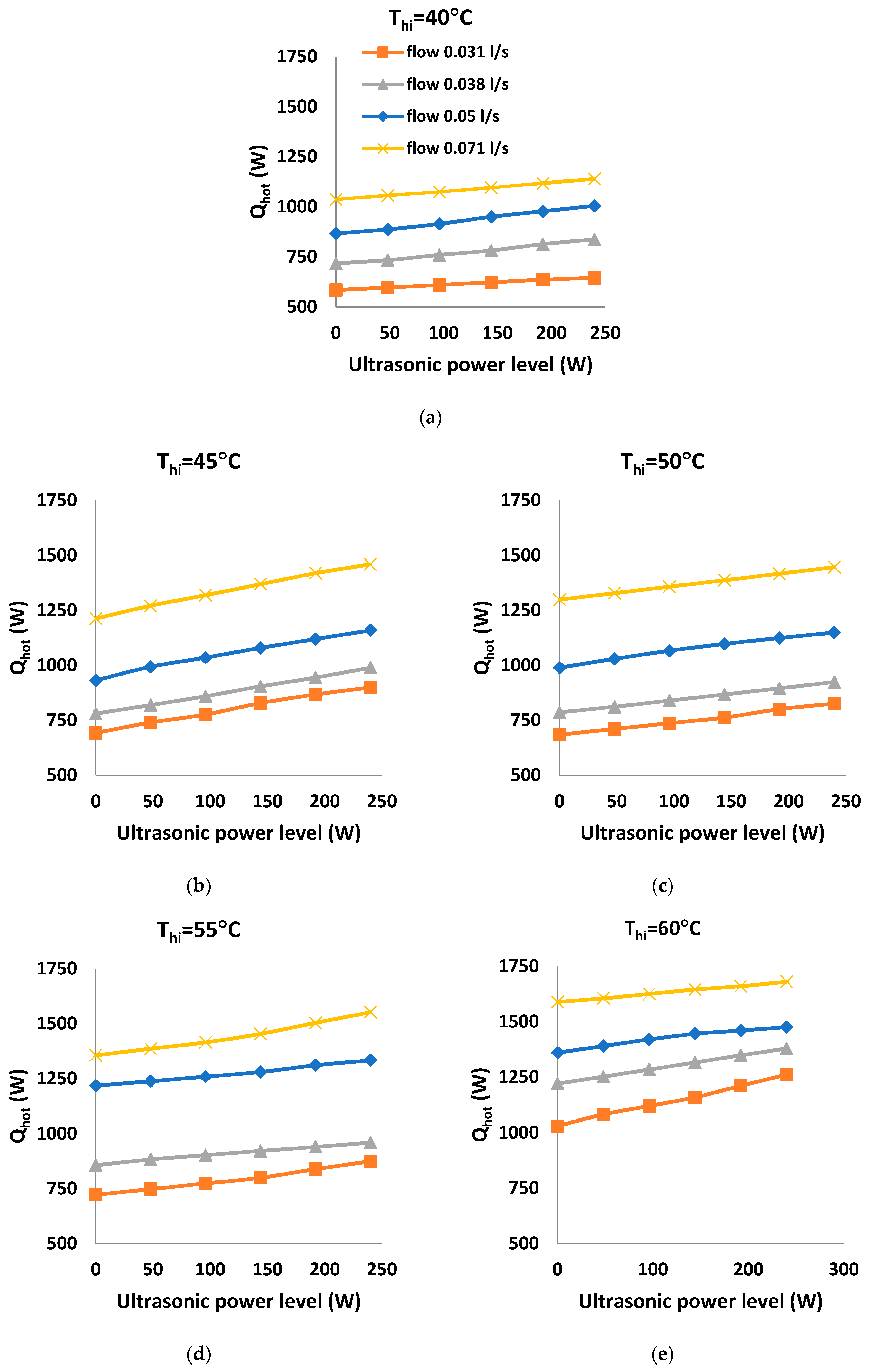
5.3. Variation of Ultrasonic Power Levels

Figure 5a,b present the percentage increase in the convection coefficient resulting from the presence of UWs at different flow rates and varying hot water temperatures (specifically, 40 °C and 60 °C). In Equation (6), the parameter Ev is introduced and calculated as the enhancement in the convection coefficient, representing the difference between the convection coefficient with and without UWs. The graphs illustrate that, as the power of the waves increases, Ev also increases for a given flow rate of the hot fluid. However, this increase is more significant at lower flow rates. For example, at a flow rate of 0.071 L/s of hot water at 40 °C within the central tube of the DPHX, with an ultrasonic amplitude of 0.8 A, Ev exhibits a 34% increase. Conversely, for the same power and hot water temperature, when the flow rate reduces to 0.031 L/s of hot water, Ev reaches 1.83, indicating an 83% increase in the convection coefficient.
In the experiment conducted with a hot fluid temperature of 60 °C and an ultrasonic amplitude of 0.8 A, there was an observed enhancement in the convection coefficient. Specifically, at a flow rate of 0.071 L/s, the convection coefficient of the hot water improved by approximately 42%. Similarly, at a flow rate of 0.031 L/s, the improvement reached a value of 85%. Furthermore, when the same temperature was maintained but with an ultrasonic amplitude of 0.2 A, the convection coefficient showed significant improvements, too. For flow rates of 0.071 L/s, 0.05 L/s, 0.038 L/s, and 0.031 L/s, the use of UWs resulted in approximate improvements of 23%, 31%, 40%, and 42%, respectively, compared with cases without UWs. At a power level of 144 W (equivalent to 0.6 A), notable improvements in the convection coefficient were observed for various flow rates. Specifically, enhancements of approximately 33%, 45%, 56%, and 72% were achieved for flow rates of 0.071 L/s, 0.05 L/s, 0.038 L/s, and 0.031 L/s, respectively.
Furthermore, the comparison of Figure 5a,b reveals that the variation in the inlet temperature of the hot fluid does not exert a substantial influence on the values of Ev. For instance, at a temperature of 40 °C, with hot water having a power of 240 W and a flow rate of 0.071 L/s, the increase in the convection coefficient was measured at 2.01. Similarly, at a temperature of 60 °C under the same power and flow rate, the increase reached 2.05. However, when comparing a temperature of 40 °C and 60 °C for hot water with a power of 96 W and a flow rate of 0.071 L/s, the increase in the convection coefficient was 21% and 25%, respectively, indicating a relatively insignificant difference.

5.4. Variation of Heat Transfer Rate

Figure 6a–e depict the convective heat transfer variations of a hot fluid over a temperature range of 40 to 60 °C, with a temperature interval of 5 °C. The plots compare scenarios without UWs (i.e., zero ultrasonic power level) against the presence of UWs at power levels ranging from 48 to 240 W. These experiments were conducted at different flow rates of the hot water to facilitate comparison, and the resulting curves for various flow rates are overlaid on the same graph.
As expected, the graphs clearly demonstrate that increasing the applied power corresponds to an increase in the convective heat transfer rate, denoted as Qh. In simpler terms, the heat transfer rate rises in tandem with the power of the UWs, regardless of the specific flow rate.
In the end, it should be noted that, although our initial study primarily focused on the individual impacts of ultrasonic power levels and hot water flow rates, we recognize the importance of understanding their combined effects for a comprehensive analysis. The interaction between ultrasonic power and hot water flow rate can be attributed to several mechanisms, including cavitation enhancement, turbulence augmentation, and boundary layer disruption. To provide a thorough understanding of these interactions, future studies may focus on utilizing statistical methods, such as factorial design and response surface methodology, to analyze the interaction effects and identify optimal parameter combinations. Additionally, developing computational models to simulate the coupled effects of ultrasonic power and flow rate on heat transfer can provide deeper insights into the underlying mechanisms.
Also, this paper focuses on the enhancement of heat transfer using UWs. While we did not directly test the long-term effects of UWs on HX materials, these effects have been examined in previous work on DPHXs [43]. The literature review shows that these effects include potential material degradation, changes in thermal and mechanical properties, and altered corrosion resistance. These insights underscore the importance of considering long-term implications to ensure the durability and sustainability of HX materials in industrial applications.

6. Conclusions

This investigation aimed to explore the impact of UWs on enhancing heat transfer within a water–water DPHX experimentally. The precision of the gathered data was assessed through energy balance evaluation. Additionally, a validation test employing established empirical relations was utilized. Various configurations of fluid flow, thermophysical conditions, and UW characteristics were examined during the experiment. The results indicate that increasing the power of the waves, for a given flow rate of the hot fluid, leads to a higher augmentation in the convection coefficient when ultrasound is present compared with when ultrasound waves are absent. However, this augmentation is more pronounced at lower flow rates. In these experiments, the maximum enhancement surpasses 100%, occurring at an inlet temperature of 60 °C with an ultrasonic power setting of 240 W. Additionally, the Nusselt number for the hot fluid rises with an increase in flow rate, with these changes being more marked when UWs are utilized. Given the scarcity of data on heat transfer characteristics in DPHXs assisted by UWs, the quantified information presented herein could offer valuable insights for optimizing such heat exchange systems. In future work, it would be beneficial to extend the experimental framework to include a broader range of ultrasonic power levels, inlet temperatures, and frequencies. Such expansions would facilitate a more comprehensive understanding of the phenomena under investigation and enhance the external validity of the results. Also, the current results provide a solid foundation for further investigation to optimize the heat transfer enhancement using UWs.

Author Contributions

A.J.: Conceptualization, Methodology, and Writing—Original Draft Preparation; A.A.D.: Formal Analysis, Investigation, and Validation; M.R.Z.: Methodology and Investigation; S.A.T.: Methodology and Investigation. All authors reviewed the manuscript. All authors have read and agreed to the published version of the manuscript.

Funding

This research received no external funding.

Data Availability Statement

Dataset available on request from the authors.

Conflicts of Interest

The authors declare no conflict of interest.

Declaration of AI and AI-Assisted Technologies in the Writing Process

During the preparation of this work, the authors used ChatGPT 3.5 to identify improvements in the writing style. After using this tool, the authors reviewed and edited the content as needed and took full responsibility for the content of the publication.

References

  1. Omidi, M.; Farhadi, M.; Jafari, M. A comprehensive review on double pipe heat exchangers. Appl. Therm. Eng. 2017, 110, 1075–1090. [Google Scholar] [CrossRef]
  2. Musielak, G. Modeling of heat and mass transfer during ultrasound-assisted drying of a packed bed consisting of highly shrinkable material. Chem. Eng. Res. Des. 2018, 129, 25–33. [Google Scholar] [CrossRef]
  3. Cao, X.; Zhang, M.; Mujumdar, A.S.; Zhong, Q.; Wang, Z. Effects of ultrasonic pretreatments on quality, energy consumption and sterilization of barley grass in freeze drying. Ultrason. Sonochem. 2018, 40, 333–340. [Google Scholar] [CrossRef] [PubMed]
  4. Gao, P.; Zhou, X.; Cheng, B.; Zhang, D.; Zhou, G. Study on heat and mass transfer of droplet cooling in ultrasound wave. Int. J. Heat Mass Transf. 2016, 107, 916–924. [Google Scholar] [CrossRef]
  5. Rostami, Z.; Rahimi, M.; Azimi, N. Using high-frequency ultrasound waves and nanofluid for increasing the efficiency and cooling performance of a PV module. Energy Convers. Manag. 2018, 160, 141–149. [Google Scholar] [CrossRef]
  6. Thomä, M.; Wagner, G.; Straß, B.; Wolter, B.; Benfer, S.; Fürbeth, W. Ultrasound enhanced friction stir welding of aluminum and steel: Process and properties of EN AW 6061/DC04-Joints. J. Mater. Sci. Technol. 2018, 34, 163–172. [Google Scholar] [CrossRef]
  7. Bouazaoui, O.; Chouaf, A. Characterization of Defects in Termite Welds Rails by Ultrasound Method. Procedia Eng. 2017, 181, 991–998. [Google Scholar] [CrossRef]
  8. Reuter, F.; Lauterborn, S.; Mettin, R.; Lauterborn, W. Membrane cleaning with ultrasonically driven bubbles. Ultrason. Sonochem. 2017, 37, 542–560. [Google Scholar] [CrossRef] [PubMed]
  9. Luján-Facundo, M.-J.; Mendoza-Roca, J.-A.; Cuartas-Uribe, B.; Álvarez-Blanco, S. Membrane fouling in whey processing and subsequent cleaning with ultrasounds for a more sustainable process. J. Clean. Prod. 2017, 143, 804–813. [Google Scholar] [CrossRef]
  10. Luo, X.; Cao, J.; Yan, H.; Gong, H.; Yin, H.; He, L. Study on separation characteristics of water in oil (W/O) emulsion under ultrasonic standing wave field. Chem. Eng. Process. Process Intensif. 2018, 123, 214–220. [Google Scholar] [CrossRef]
  11. Carletti, C.; De Blasio, C.; Miceli, M.; Pirone, R.; Westerlund, T. Ultrasonic enhanced limestone dissolution: Experimental and mathematical modeling. Chem. Eng. Process.—Process. Intensif. 2017, 118, 26–36. [Google Scholar] [CrossRef]
  12. Li, K.W.; Parker, J.D. Acoustical effects on free convective heat transfer from a horizontal wire. J. Heat Transf. 1967, 89, 277–278. [Google Scholar] [CrossRef]
  13. Bergles, A.; Newell, P. The influence of ultrasonic vibrations on heat transfer to water flowing in annuli. Int. J. Heat Mass Transf. 1965, 8, 1273–1280. [Google Scholar] [CrossRef]
  14. Kim, H.Y.; Kim, Y.G.; Kang, B.H. Enhancement of natural convection and pool boiling heat transfer via ultrasonic vibration. Int. J. Heat Mass Transf. 2004, 47, 2831–2840. [Google Scholar] [CrossRef]
  15. Loh, B.-G.; Hyun, S.; Ro, P.I.; Kleinstreuer, C. Acoustic streaming induced by ultrasonic flexural vibrations and associated enhancement of convective heat transfer. J. Acoust. Soc. Am. 2002, 111, 875–883. [Google Scholar] [CrossRef] [PubMed]
  16. Setareh, M.; Saffar-Avval, M.; Abdullah, A. Experimental and numerical study on heat transfer enhancement using ultrasonic vibration in a double-pipe heat exchanger. Appl. Therm. Eng. 2019, 159, 113867. [Google Scholar] [CrossRef]
  17. Komarov, S.; Hirasawa, M. Enhancement of gas phase heat transfer by acoustic field application. Ultrasonics 2003, 41, 289–293. [Google Scholar] [CrossRef] [PubMed]
  18. Monnot, A.; Boldo, P.; Gondrexon, N.; Bontemps, A. Enhancement of Cooling Rate by Means of High Frequency Ultrasound. Heat Transf. Eng. 2007, 28, 3–8. [Google Scholar] [CrossRef]
  19. Gondrexon, N.; Rousselet, Y.; Legay, M.; Boldo, P.; Le Person, S.; Bontemps, A. Intensification of heat transfer process: Improvement of shell-and-tube heat exchanger performances by means of ultrasound. Chem. Eng. Process.—Process. Intensif. 2010, 49, 936–942. [Google Scholar] [CrossRef]
  20. Legay, M.; Simony, B.; Boldo, P.; Gondrexon, N.; Le Person, S.; Bontemps, A. Improvement of heat transfer by means of ultrasound: Application to a double-tube heat exchanger. Ultrason. Sonochem. 2011, 19, 1194–1200. [Google Scholar] [CrossRef]
  21. Legay, M.; Le Person, S.; Gondrexon, N.; Boldo, P.; Bontemps, A. Performances of two heat exchangers assisted by ultrasound. Appl. Therm. Eng. 2012, 37, 60–66. [Google Scholar] [CrossRef]
  22. Delouei, A.A.; Sajjadi, H.; Atashafrooz, M.; Hesari, M.; Hamida, M.B.B.; Arabkoohsar, A. Louvered fin-and-flat tube compact heat exchanger under ultrasonic excitation. Fire 2023, 6, 13. [Google Scholar] [CrossRef]
  23. Delouei, A.A.; Sajjadi, H.; Ahmadi, G. Ultrasonic Vibration Technology to Improve the Thermal Performance of CPU Water-Cooling Systems: Experimental Investigation. Water 2022, 14, 4000. [Google Scholar] [CrossRef]
  24. Delouei, A.A.; Sajjadi, H.; Ahmadi, G. The Effect of Piezoelectric Transducer Location on Heat Transfer Enhancement of an Ultrasonic-Assisted Liquid-Cooled CPU Radiator. Iran. J. Sci. Technol. Trans. Mech. Eng. 2024, 48, 239–252. [Google Scholar] [CrossRef]
  25. Hedeshi, M.; Jalali, A.; Arabkoohsar, A.; Delouei, A.A. Nanofluid as the working fluid of an ultrasonic-assisted double-pipe counter-flow heat exchanger. J. Therm. Anal. Calorim. 2023, 148, 8579–8591. [Google Scholar] [CrossRef]
  26. Tafarroj, M.M.; Delouei, A.A.; Hajjar, A.; Ben Hamida, M.B.; Izadi, M. MLP and optimized FCM-ANFIS models proposed for inlet turbulent flow under ultrasonic vibration. J. Therm. Anal. Calorim. 2023, 148, 13995–14009. [Google Scholar] [CrossRef]
  27. Esfandyari, M.; Delouei, A.A.; Jalai, A. Optimization of ultrasonic-excited double-pipe heat exchanger with machine learning and PSO. Int. Commun. Heat Mass Transf. 2023, 147, 106985. [Google Scholar] [CrossRef]
  28. Dhanalakshmi, N.P.; Nagarajan, R.; Sivagaminathan, N.; Prasad, B.V.S.S.S. Acoustic enhancement of heat transfer in furnace tubes. Chem. Eng. Process. Process Intensif. 2012, 59, 36–42. [Google Scholar] [CrossRef]
  29. Legay, M.; Gondrexon, N.; Le Person, S.; Boldo, P.; Bontemps, A. Enhancement of Heat Transfer by Ultrasound: Review and Recent Advances. Int. J. Chem. Eng. 2011, 2011, 670108. [Google Scholar] [CrossRef]
  30. Hosseinian, A.; Isfahani, A.H.M.; Shirani, E. Experimental investigation of surface vibration effects on increasing the stability and heat transfer coefficient of MWCNTs-water nanofluid in a flexible double pipe heat exchanger. Exp. Therm. Fluid Sci. 2018, 90, 275–285. [Google Scholar] [CrossRef]
  31. Rafati, M.; Hamidi, A.; Niaser, M.S. Application of nanofluids in computer cooling systems (heat transfer performance of nanofluids). Appl. Therm. Eng. 2012, 45, 9–14. [Google Scholar] [CrossRef]
  32. Delouei, A.A.; Naeimi, H.; Sajjadi, H.; Atashafrooz, M.; Imanparast, M.; Chamkha, A.J. An active approach to heat transfer enhancement in indirect heaters of city gate stations: An experimental modeling. Appl. Therm. Eng. 2024, 237, 121795. [Google Scholar] [CrossRef]
  33. Nazari, M.; Ashouri, M.; Kayhani, M.H.; Tamayol, A. Experimental study of convective heat transfer of a nanofluid through a pipe filled with metal foam. Int. J. Therm. Sci. 2015, 88, 33–39. [Google Scholar] [CrossRef]
  34. Kayhani, M.H.; Soltanzadeh, H.; Heyhat, M.M.; Nazari, M.; Kowsary, F. Experimental study of convective heat transfer and pressure drop of TiO2/water nanofluid. Int. Commun. Heat Mass Transf. 2012, 39, 456–462. [Google Scholar] [CrossRef]
  35. Moffat, R.J. Describing the uncertainties in experimental results. Exp. Therm. Fluid Sci. 1988, 1, 3–17. [Google Scholar] [CrossRef]
  36. Zarembo, L.K. Acoustic streaming. In High-Intensity Ultrasonic Fields; Rozenberg, L.D., Ed.; Plenum Press: New York, NY, USA, 1971. [Google Scholar]
  37. Eckart, C. Vortices and Streams Caused by Sound Waves. Phys. Rev. B 1948, 73, 68–76. [Google Scholar] [CrossRef]
  38. Ashokkumar, M. The characterization of acoustic cavitation bubbles—An overview. Ultrason. Sonochem. 2011, 18, 864–872. [Google Scholar] [CrossRef]
  39. Yuan, M.; Li, C.; Ge, J.; Xu, Q.; Li, Z. Study on the Motion Characteristics of Solid Particles in Fine Flow Channels by Ultrasonic Cavitation. Micromachines 2022, 13, 1196. [Google Scholar] [CrossRef]
  40. Xiao, J. Thermoacoustic heat transportation and energy transformation Part 2: Isothermal wall thermoacoustic effects. Cryogenics 1995, 35, 21–26. [Google Scholar] [CrossRef]
  41. Cai, J.; Huai, X.; Liang, S.; Li, X. Augmentation of natural convective heat transfer by acoustic cavitation. Front. Energy Power Eng. China 2010, 4, 313–318. [Google Scholar] [CrossRef]
  42. Fairbanks, H.V. Influence of ultrasound upon heat transfer systems. In Proceedings of the Ultrasonics Symposium, New Orleans, LA, USA, 26–28 September 1979; pp. 384–387. [Google Scholar]
  43. Legay, M.; Allibert, Y.; Gondrexon, N.; Boldo, P.; Le Person, S. Experimental investigations of fouling reduction in an ultrasonically-assisted heat exchanger. Exp. Therm. Fluid Sci. 2013, 46, 111–119. [Google Scholar] [CrossRef]
  44. Fu, Y.; Bian, B.; Liu, Y.; Zhang, L.; Li, M.; Wen, J.; Xu, G. Airside heat transfer analysis using Wilson plot method of three analogous serpentine tube heat exchangers for aero-engine cooling. Appl. Therm. Eng. 2024, 248, 123238. [Google Scholar] [CrossRef]
  45. Sun, W.; Zhang, X.; Liu, B.; Zhao, L.; Cheng, Q.; Wang, Z. Analysis of the main influencing factors of waste heat utilization effectiveness in the tank storage receiving process of waxy crude oil under dynamic liquid level conditions. Renew. Energy 2024, 228, 120707. [Google Scholar] [CrossRef]
  46. Gnielinski, V. New equations for heat and mass transfer in turbulent pipe and channel flow. Int. Chem. Eng. 1976, 16, 359–368. [Google Scholar]
  47. Petukhov, B.S. Advances in Heat Transfer; Irvine, T.F., Hartnett, J.P., Eds.; Academic Press: New York, NY, USA, 1970. [Google Scholar]
Figure 1. Snapshot of experimental system.
Processes 12 01333 g001
Figure 2. Schematic of experimental system.
Processes 12 01333 g002
Figure 3. Nusselt number versus Reynolds number obtained by Gnielinski equation [46] and current experimental results.
Processes 12 01333 g003
Figure 4. Variation of convection coefficient against hot flow rate in (a) non-vibration conditions and in the presence of UWs with different amplitudes of (b) UA = 0.2 A, (c) UA = 0.4 A, (d) UA = 0.6 A, (e) UA = 0.8 A, and (f) UA = 1.0 A.
Processes 12 01333 g004aProcesses 12 01333 g004b
Figure 5. Variation of Ev values with respect to the ultrasonic amplitude at a temperature of (a) 40 °C and (b) 60 °C.
Processes 12 01333 g005
Figure 6. Variation of heat transfer from hot water at different ultrasonic power levels and flow rates with a hot water temperature of (a) 40 °C, (b) 45 °C, (c) 50 °C, (d) 55 °C, and (e) 60 °C.
Processes 12 01333 g006
Table 1. Energy balance under non-vibrating and ultrasonic vibrating conditions.
Tco
(°C)
Tho
(°C)
Qc
(W)
Qh
(W)
PUS
(W)
Qloss
(W)
Error
(%)
26.745.6128913000−100.01
28.745.116681447240−192.6
Disclaimer/Publisher’s Note: The statements, opinions and data contained in all publications are solely those of the individual author(s) and contributor(s) and not of MDPI and/or the editor(s). MDPI and/or the editor(s) disclaim responsibility for any injury to people or property resulting from any ideas, methods, instructions or products referred to in the content.

