Article

Influence of Laser Scanning Speed on Wear and Corrosion Resistance of Aluminum–Nickel Coating on Magnesium Alloy

1
Department of Mechanical Engineering, Northeast Electric Power University, No. 169 Changchun Road, Jilin 132012, China
2
School of Mechanical Electrical Engineering, Jilin Institute of Chemical Technology, Jilin 132022, China
*
Author to whom correspondence should be addressed.
Processes 2024, 12(8), 1689; https://doi.org/10.3390/pr12081689
Submission received: 5 July 2024 / Revised: 7 August 2024 / Accepted: 8 August 2024 / Published: 13 August 2024
(This article belongs to the Special Issue Microstructure, Processing and Numerical Simulation of Coatings)

Abstract

:
To improve the wear and corrosion resistance, Al-Ni coating was prepared on Mg alloy by laser cladding, and the influence of the laser scanning speed on the microstructure, wear and corrosion resistance of the coatings was systematically analyzed. The results showed that the coatings with different scanning speeds were composed of Al3Ni2, Mg17Al12 and Mg2Al3 phases. The coatings presented fine needle-like grains. Under different scanning speeds, the microhardness of the coatings was 3.3–4.8 times that of the substrate, and the wear volume of the coatings was decreased by 40.08–51.38%. The coating with a laser scanning speed of 600 mm/min had the highest hardness, the best wear and corrosion resistance.

1. Introduction

As Mg is one of the lightest metallic materials, Mg alloy has excellent properties including high specific stiffness and strength, and good shock absorption; thus, it is widely used in the aerospace, electronics and automotive industries [1,2,3,4]. However, the low hardness and wear resistance, poor corrosion resistance and plastic deformation limit the long-term use of these alloys in industry [5,6,7,8]. Therefore, many research works have focused on improving the performance of magnesium alloy by applying surface processing technology [9,10,11,12]. Mohammad Diab et al. [13]. prepared a pure aluminum coating on the AZ31B magnesium alloy by using cold spraying technology. In a salt fog environment, the Al coating kept a lower corrosion rate; the rate increased at cycle 40, but it was still significantly lower than that of the magnesium alloy substrate. Usman Ahmed et al. [14] designed an Al + Al2O3 + CNT coating on the LA43M magnesium alloy. The coating was composed of an FCC phase and had a hardness of 91.11 ± 1.71 HV, self-corrosion potential of −0.93 ± 0.04 V, self-corrosion current density of 0.87 ± 0.45 μA/cm2 and wear rate of 4.43 × 10⁻⁴ ± 3.41 × 10⁻⁵ mm2/m. Laser cladding technology has also been widely used in the surface treatment of Mg alloys due to its high energy density and rapid prototyping of complex structural parts, which significantly improve the surface hardness and abrasion resistance of Mg alloys, and it has received close attention from scholars at home and abroad [15,16,17].
Al alloys have similar melting points to Mg alloys, and they have good corrosion resistance and metallurgical bonding performance. According to the Al-Mg phase diagram, Al and Mg form hard phases such as Mg17Al12, and a limited solid solution can be formed at a eutectic temperature (437 °C), which effectively improves the hardness and strength of the alloy [18,19]. Therefore, there are many research reports on laser cladding of Al-based alloys on the surface of magnesium alloys to improve wear resistance and corrosion resistance. The binary alloy coatings mainly consist of two types: Al-Si and Al-Cu. Zhang [20] applied laser cladding Al-Si powders on Mg-6Zn-1Ca magnesium alloy. The microhardness of the clad layer (HV0.025 310) was about five times higher than that of the substrate (HV0.025 54). The corrosion potential was increased to −129 mV, compared to −1575 mV for the untreated sample. Lei [21] used Al-Si eutectic alloy powders to fabricate Al-Si coatings on the AZ91D magnesium alloy by using laser cladding. The Al-Si coating has good metallurgical bonds and a dense, crack- and pore-free structure. The coating consisted of a bright needle-like Al3Mg2 phase, Mg17Al12 matrix and Mg2Si dendrites. The bottom part of the coating was formed of dendritic α-Mg solid solution, an irregular block Mg2Si phase and rosette eutectics (α-Mg + Mg17Al12).
Wan [22] prepared Cu3-Al, Cu6-Al and Cu9-Al coatings on Mg-Li alloy using laser cladding. The hardness, wear and corrosion properties of Cu6-Al coating were the best. When compared with the Mg-Li alloy substrate, the average hardness of Cu6-Al coating increases by 6.75 times. The wear volume of Cu6-Al coating is 11.68% that of the substrate, and the corrosion current density decreases by two orders of magnitude compared to the substrate. Gao [23] used laser cladding to prepare Al-Cu coating on the AZ91HP magnesium alloy. The Al-Cu coating was characterized by AlCu4 and Mg17Al12 grains embedded in an AlMg matrix. The bonding zone exhibited a white-light planar crystal band with a thickness of 10–13 mm. Due to the hard phases of AlCu4 and Mg17Al12 in the coating, the microhardness and wear resistance of the coating were improved. Owing to the formation of a dense Al2O3 oxide film during the electrochemical corrosion experiment under the simulated environment of 3.5 wt. % NaCl solution, the coating exhibited better corrosion resistance.
Al-Ni alloy and Mg alloy have good physicochemical compatibility, and they form Al-Mg hard phases to improve the wear and corrosion resistance. Therefore, we carried out laser cladding to apply an Al-Ni alloy coating on Mg alloy, and herein we systematically discuss the influence of laser scanning on the microstructure and properties of coatings.

2. Materials and Methods

2.1. Sample Preparation

AZ91HP Mg alloy with the size of 50 mm × 30 mm × 10 mm was selected as the substrate in this study. The chemical composition is shown in Table 1. The microstructure of AZ91HP Mg alloy is illustrated in Figure 1, composed of primary α-Mg with 150–200 μm (Figure 1a), eutectic α-Mg and divorced eutectic β-Mg17Al12 at grain boundaries (Figure 1b).
To reduce the physical and chemical differences between the coating and the substrate, for the materials of the coatings, we selected pure Al and Ni powders with a molar ratio of 4:1. The powders were procured from Xingtai Xinnai Metal Materials Co., Ltd., Xingtai, China. The particle size and purity of the powders were 50~80 μm and 99.0~99.5%, respectively. The powders were weighed according to the mass percentages shown in Table 2, and fully mixed with a KE-0.4L planetary ball mill. The parameters were set as follows: the speed was 240 r/min, the ball–powder ratio (mass ratio) was 2:1 and the time was 2 h.
Before conducting the laser cladding experiment, using 600-mesh sandpaper, we polished the surface of the AZ91HP substrate to remove any stains and oxide layers. After polishing, the surface of the sample was cleaned and dried.

2.2. Laser Cladding

On the surface of the AZ91HP substrate, the laser cladding experiments were carried out using a DL-HL-T200 cross-flow CO2 laser (Shenyang Continental Laser Complete Equipment Co., Ltd., Shenyang, China). The experimental parameters are shown in Table 3.
After the laser cladding experiments, when the samples were cooled, they were cut into small samples by the wire cutting method. The cross-section of the samples was roughly ground, fine ground and polished, and then it was cleaned and dried to make the metallographic samples.

2.3. Microstructural Characterization and Property Measurement

The phases of Al-Ni coatings were detected and analyzed by a TD-3500X ray diffractometer (Cu target) (Dandong Tongda Technology Co., Ltd., Dandong, China). The parameters were as follows: the diffraction angle range was 2θ = 20°~80°, the scanning speed was 4.080°/min and the sampling time was 2 s.
We used a ZEISS Gemini SEM (Zeiss, Oberkochen, Germany) to observe the microstructure of Al-Ni coatings, and the elements’ distribution and contents of the coatings were detected by an Energy Dispersive Spectrometer.
The microhardness of Al-Ni coatings was measured by an HXD-1000TMC/LCD microhardness tester (Wuxi Metes Precision Technology Co., Ltd., Wuxi, China). The measurement method was as follows: From the top of the coating to the substrate, a point was made every 0.1 mm, the load was 25 g, the loading time was 10 s and the operation was repeated three times at different positions of the same layer depth. The average value was taken as the final result.
In order to study the wear resistance of Al-Ni coatings and substrate, friction and wear experiments were conducted by an MGW-02 reciprocating friction and wear tester. The experimental parameters were as follows: the load was 10 N, the frequency was 5 HZ and the experimental time was 20 min. After the experiment, the wear scar was observed by an SEM.
The electrochemical corrosion experiment of the coatings and substrate was carried out by using a CHI600E electrochemical workstation (Shanghai Chenhua Instrument Co., Ltd., Shanghai, China), which was used to study the corrosion resistance of Al-Ni coatings and substrate. The experimental method was as follows: In the experiment, a standard three-electrode cell was used for testing, with a saturated calomel electrode as the reference electrode and a platinum sheet electrode as the auxiliary electrode. The coatings and substrate test surfaces were used as working electrodes, and the remaining surfaces were sealed with epoxy resin. The samples were placed in 3.5% NaCl solution at room temperature to simulate the corrosion environment, the scanning rate of the workstation was 0.01 V/s~1 V/s, the test voltage range was −1.6 V~0.8 V and then we carried out electrochemical corrosion experiments.

3. Results and Discussion

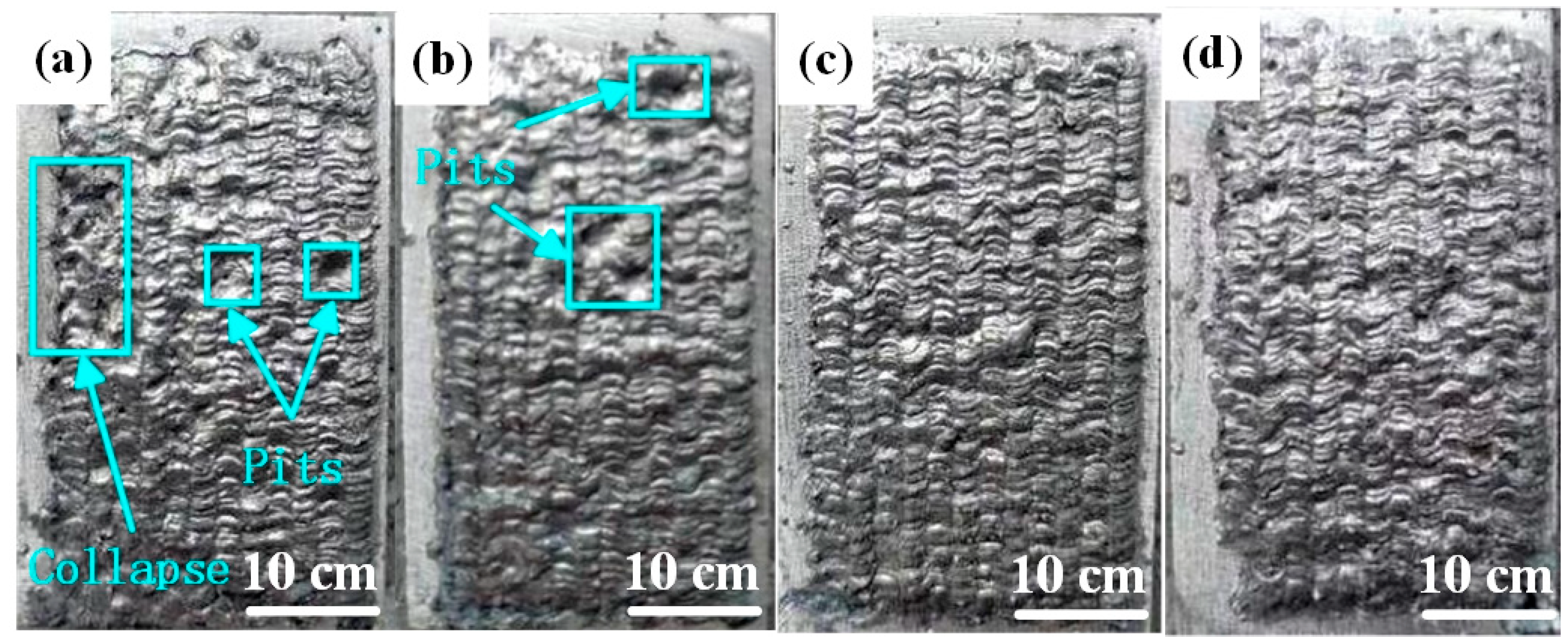
3.1. Effect of Laser Scanning Speed on Macroscopic Morphology of Al-Ni Coatings

Figure 2 illustrates the macroscopic morphology of Al-Ni coatings under different scanning speeds. When the laser scanning speed is 600 mm/min, the coating surface is smooth, has an obvious fish scale trajectory and has no blowholes or cracks, as shown in Figure 2c. However, there are molten pits on the surfaces of coatings under the speeds of 360 mm/min and 480 mm/min, as shown in Figure 2a,b. According to the analysis, when the laser scanning speed is less than 600 mm/min, some elements in the coatings are burned out due to the increase in laser specific energy, which causes the appearance of molten pits. In addition, it is easy to accumulate heat and collapse (Figure 2a) for the Al-Ni coatings at the later stage of laser cladding, which is caused by the decrease in laser scanning speed and the increase in laser specific energy.

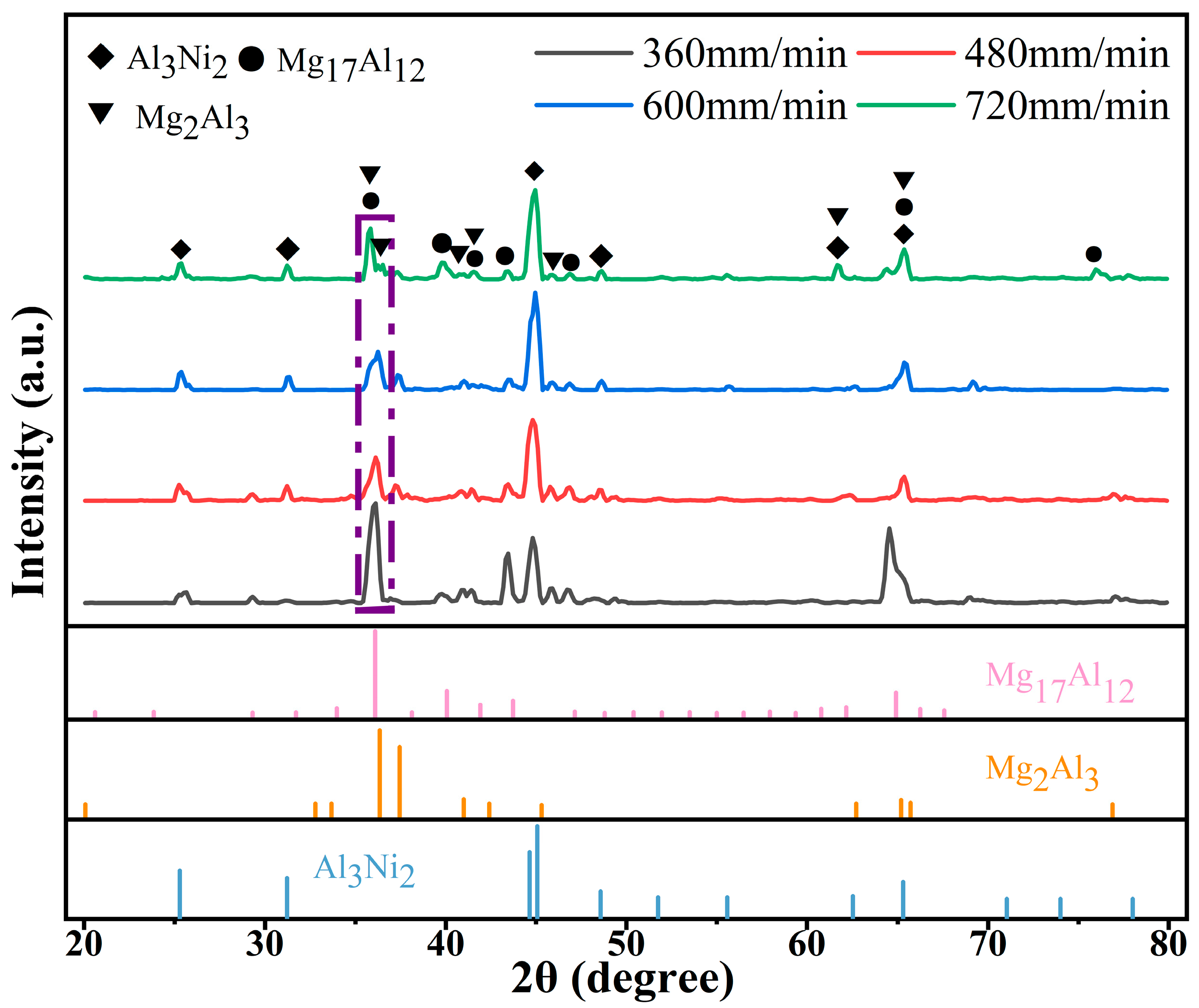
3.2. Effect of Laser Scanning Speed on Phase Composition of Al-Ni Coatings

Figure 3 shows the XRD spectrum of Al-Ni coatings under different scanning speeds. From Figure 3, it can be seen that the coatings are composed of Al3Ni2 (PDF#00-014-0648), Mg17Al12 (PDF#97-015-8247) and Mg2Al3 (PDF#00-040-0903) at all scanning speeds. Mg element diffuses into the coatings to form Mg17Al12 and Mg2Al3 phases with Al element due to the low melting point of Mg element, which ensures the metallurgical bonding between Al-Ni coatings and Mg alloy substrate.
With the increase in laser scanning speed, the diffraction peak of each coating first decreases and then increases at the diffraction angle of 35°~36°. The average grain size of the corresponding diffraction peaks can be calculated by Equation (1) [24], and the results are presented in Table 4. It can be seen that the diffraction intensity is the lowest and that the peak width at half height is the largest at a laser scanning speed of 600 mm/min. Therefore, the grain size is smallest at this time. With the decrease in laser scanning speed, the grain size becomes coarse. This is because the laser specific energy increases and the degree of undercooling decreases with the reduction in laser scanning speed. Then, the grains grow fully and the grain size becomes larger.
D = K γ β cos θ
where D is the average grain size; β is the peak width at half height; θ is the diffraction angle; K is the Scherrer constant, and K = 0.89 when β is the peak width at half height; γ is the X-ray wavelength; and γ = 1.54056 Å.

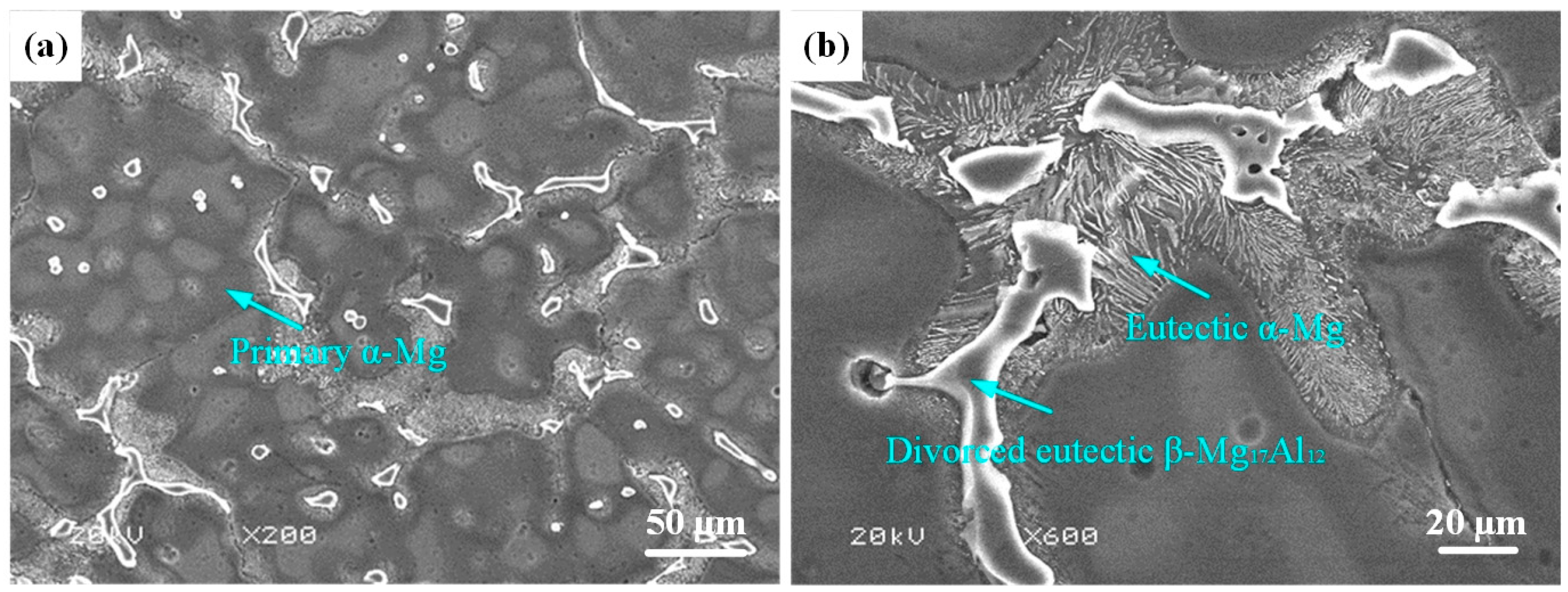
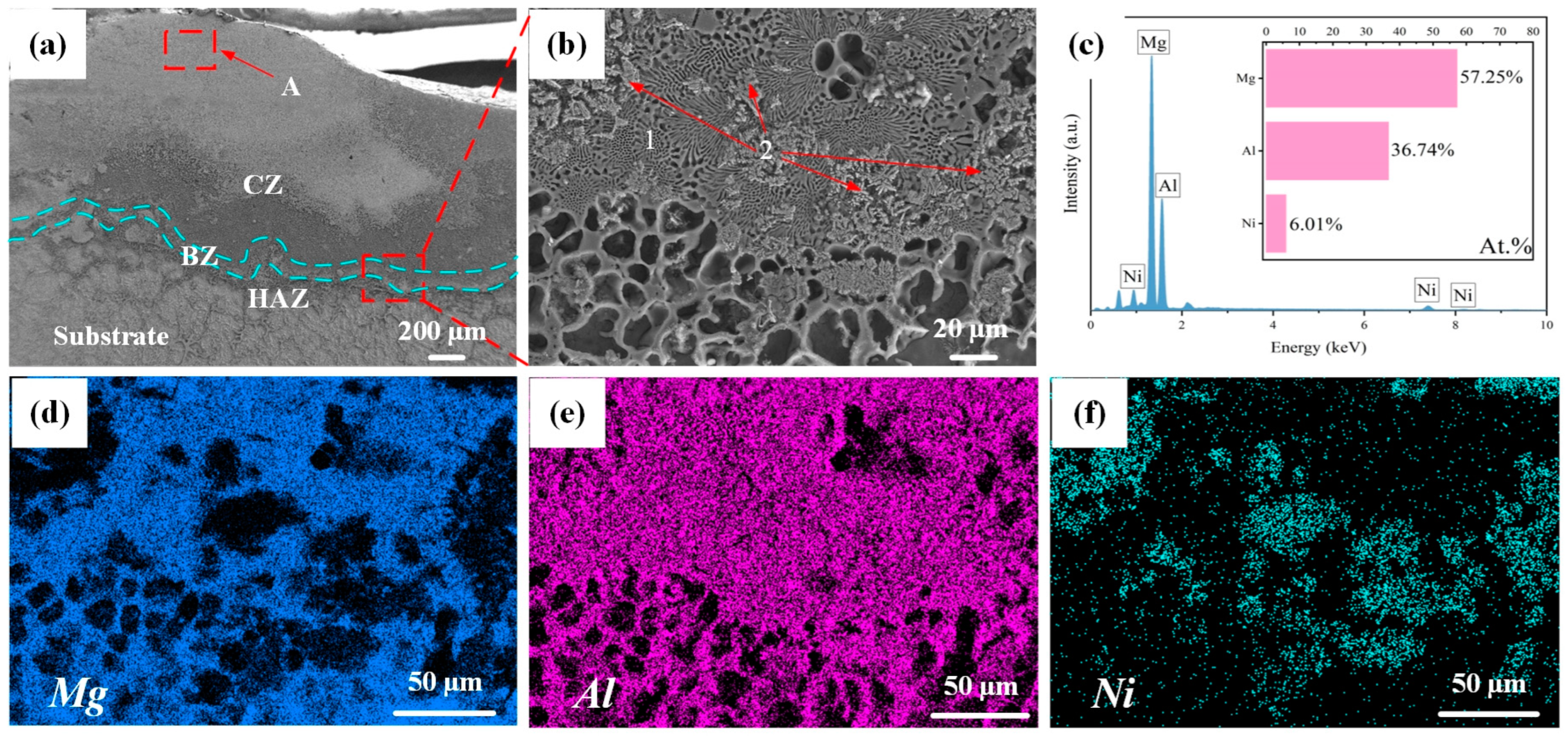
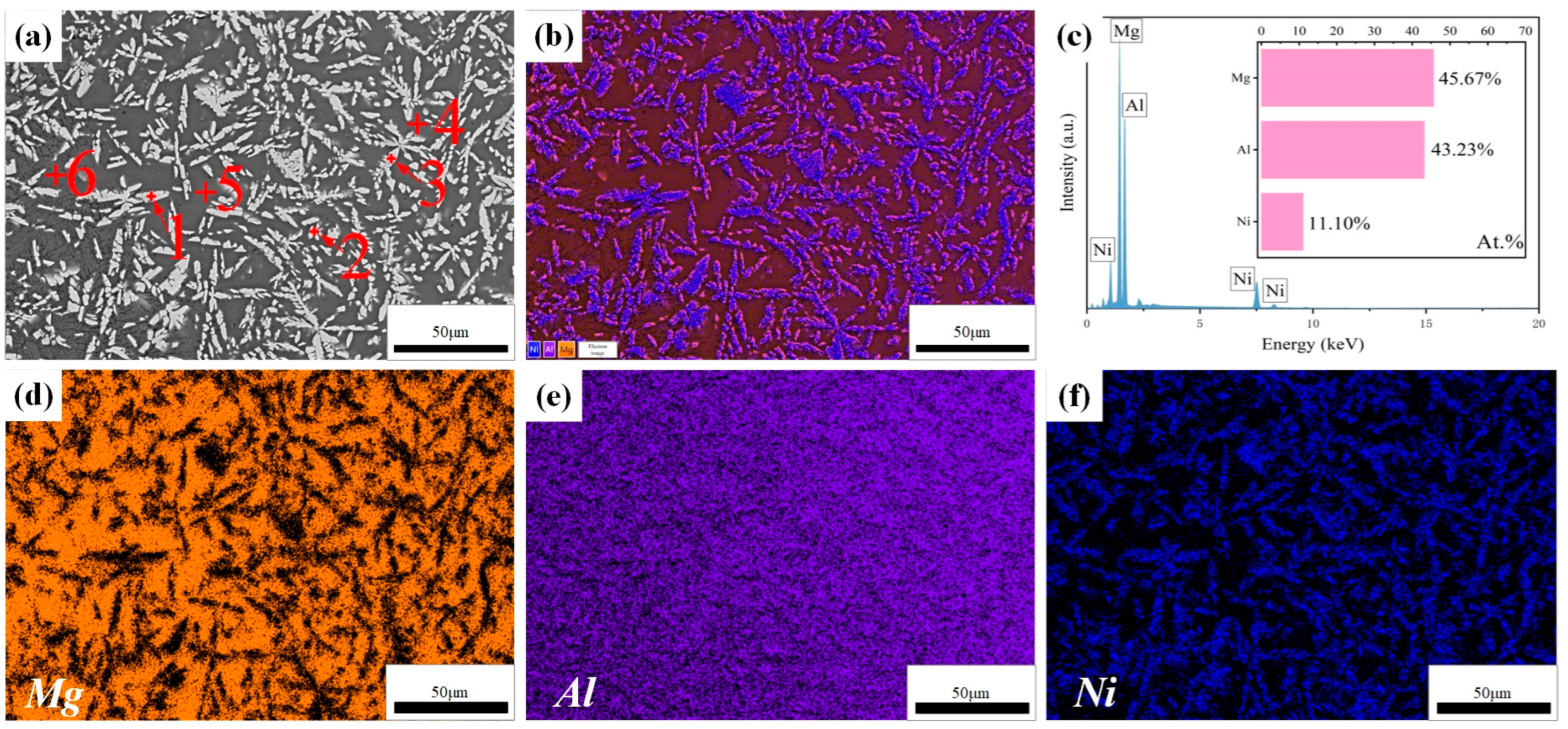
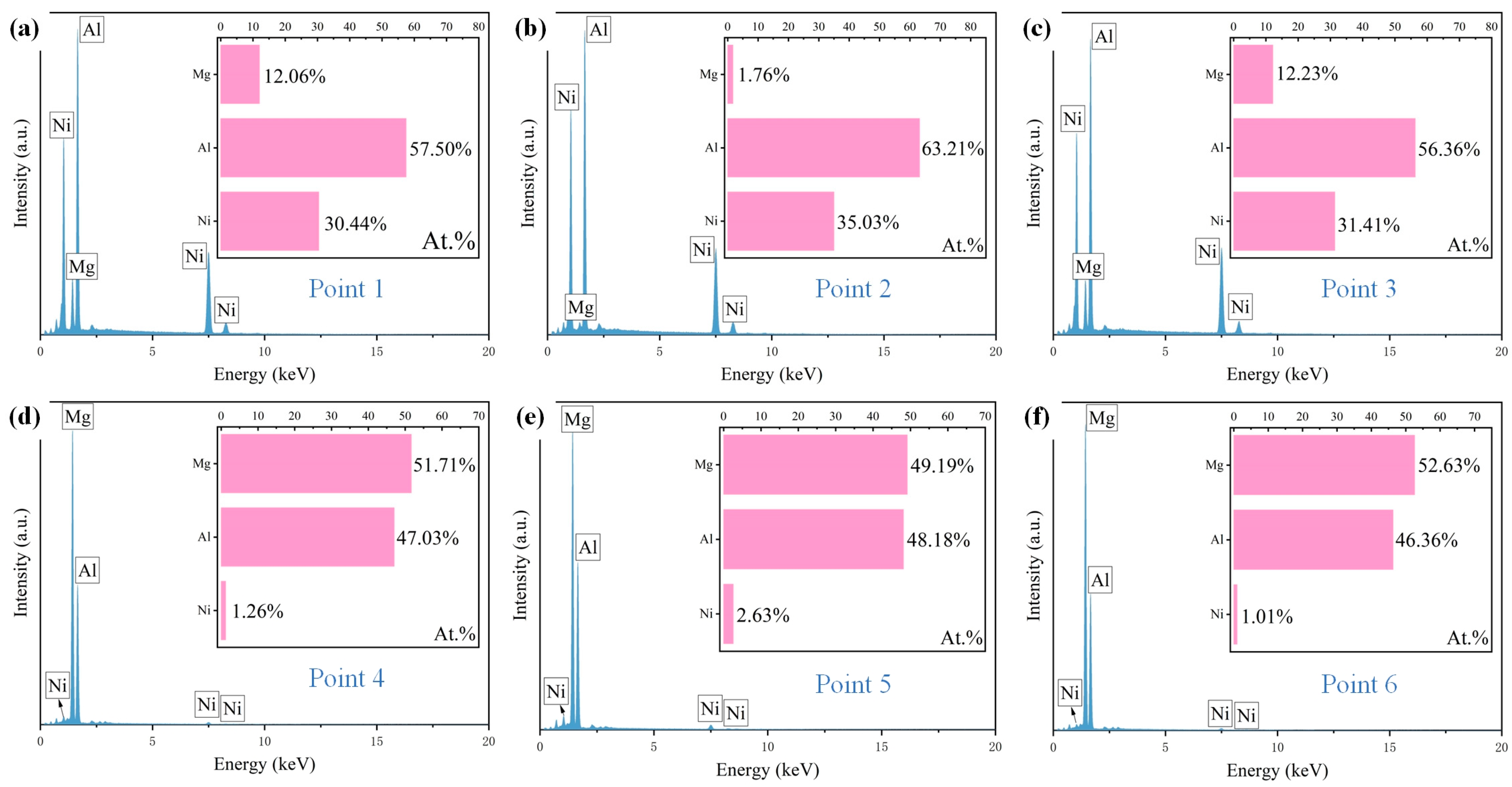
3.3. Effect of Laser Scanning Speed on Microstructure of Al-Ni Coatings

Figure 4 illustrates the cross-sectional microstructure of Al-Ni coating at a laser scanning speed of 600 mm/min. As shown in Figure 4a, the coating is comprised of a cladding zone (CZ), bonding zone (BZ), heat affected zone (HAZ) and substrate. The thickness of the coating is about 1.0 mm, which inhibits the degree to which corrosion liquid can seep into Mg alloy. In addition, it can be seen that there is a bright bonding zone between Al-Ni coating and the substrate, which indicates good metallurgical bonding between them. Figure 4b–f show an enlarged image and the map scanning results for the bonding zone. According to Figure 4c, there is a large amount of Mg element at the bonding zone, which indicates that interdiffusion of elements has occurred between Al-Ni coating and the substrate, resulting in the increase in Mg content. On the one hand, it helps to improve the bonding between Al-Ni coating and the substrate; on the other hand, Mg and Al can form hard phases such as Mg17Al12, which helps to enhance the performance of the coating. In addition, the atomic ratio of Al to Ni at the bonding zone is approximately 6:1, which is different from the designed powder ratio of 4:1. This is related to the interdiffusion of elements between Al-Ni coating and the substrate. At the same time, the burning loss of elements inevitably occurs during the laser cladding process, leading to variations in the composition of the coating. According to the results of map scanning (Figure 4d–f), Mg and Ni are mainly enriched in the lamellar structure (Point 1 in Figure 4b) and the petal-shaped phase (Point 2 in Figure 4b), respectively, and Al element is distributed in the above two structures (lamellar structure and petal-shaped phase). The results further indicate that the interdiffusion of elements in Al-Ni coating and the substrate happened at the bonding zone, which ensured that Al-Ni coating and the Mg alloy substrate had good metallurgical bonding. That is consistent with the results of the XRD analysis.
The enlarged microstructure of region A in Figure 4a is shown in Figure 5a. It can be seen that the microstructure of the cladding zone is composed of needle-like grains. To obtain the elements’ distribution, map scanning was carried out, and the result is illustrated in Figure 5b–f. It is clear that the needle-like grains have Al and Ni, and the intergranular grains have Mg and Al. In addition, in Figure 5c, it can be seen that the content of Mg element at the top of the coating is lower than that at the bonding zone, and the atomic ratio of Al and Ni is about 4:1, which indicates that the top of the coating is less affected by the dilution of Mg element.
To further determine the contents of the elements in the coating, point scanning was also carried out and the results are shown in Figure 6. According to Figure 6, the atomic ratio of Al and Ni in the needle-like grains is about 3:2, which indicates that the needle-like grains are Al3Ni2. The gray matrix region is mainly rich in Mg and Al, and the ratio is 51:47. Combined with the research of He et al. [25] and the XRD results, it can be inferred that the gray matrix region is composed of Mg2Al3 and Mg17Al12. In the solidification process of the molten pool, Al and Ni have the higher mixing enthalpy, which indicates that Al3Ni2 is preferentially formed, and then Al and Mg combine to form Mg2Al3 and Mg17Al12.
Figure 7 shows the top microstructures of Al-Ni coatings under different scanning speeds. Due to the increase in scanning speed, the cooling rate of the molten pool increases, the degree of undercooling increases, a number of nucleation particles appear in the coatings and the grains cannot grow enough, which causes grain refinement [26]. As shown in Figure 7c, the needle-like grains are the smallest when the laser scanning speed is 600 mm/min. However, at the laser scanning speed of 720 mm/min, the grain size becomes coarse. That is because the heat source moves too fast, and the degree of undercooling is too large with a high laser scanning speed. This indicates that the decrease in molecular activity in the molten pool leads to the decrease in nucleation rate; therefore, the space for grain growth increases and the grain size becomes coarse.

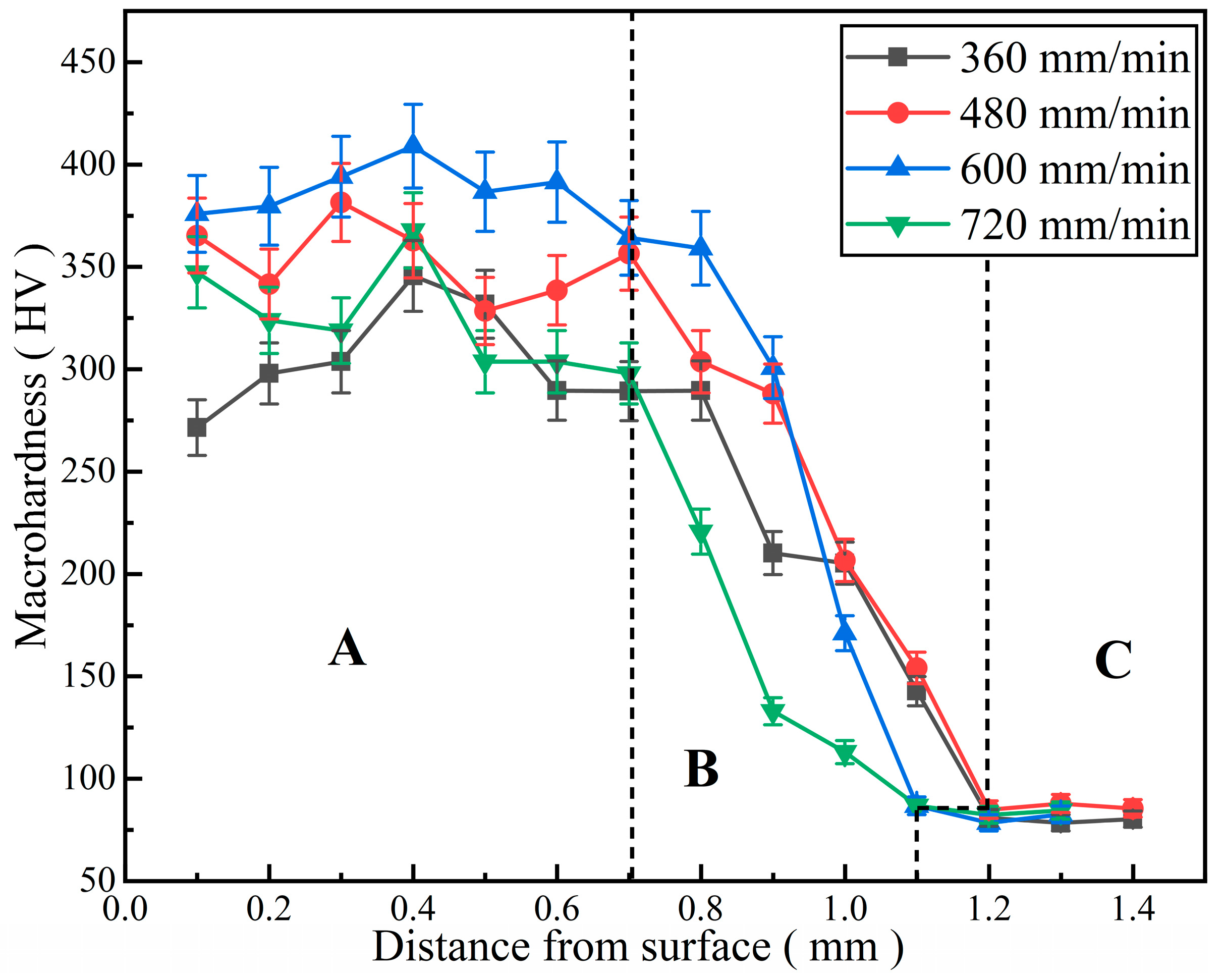
3.4. Effect of Laser Scanning Speed on Microhardness of Al-Ni Coatings

The microhardness distribution curves of Al-Ni coatings under different scanning speeds are illustrated in Figure 8. The curves can be obviously divided into three parts: A (cladding zone), B (bonding zone and heat-affected zone) and C (substrate), as shown in Figure 8. It can be seen that the microhardness of Al-Ni coatings is 3.3~4.8 times that of the substrate under different scanning speeds. This is mainly due to the following two aspects [27]: On the one hand, laser cladding technology has the feature of rapid heating and cooling, which leads to grain refinement; on the other hand, hard phases such as Al3Ni2 and Mg17Al12 are formed in the coatings, caused by element interdiffusion between the coatings and substrate. These hard phases distribute dispersedly in the coatings. Therefore, the microhardness of Al-Ni coatings increases.
In addition, the average microhardness of Al-Ni coatings first increases and then decreases with the increase in laser scanning speed. When the laser scanning speed is 600 mm/min, the coating has the highest average microhardness (385.8 HV), which is 4.8 times that of the substrate (80 HV). The coating has the lowest average microhardness (264.8 HV) at the laser scanning speed of 360 mm/min. This is caused by the low degree of undercooling, grain coarsening and the weakening of fine grain strengthening at a low laser scanning speed. According to the equation for the laser specific energy (Equation (2)) [28], this increases gradually with the decrease in the laser scanning speed. When the laser specific energy is too high, some elements in the molten pool can easily burn out, which affects the density of coatings and leads to the decreases in microhardness. Therefore, the grains are refined and the average microhardness increases (353.5 HV) at the laser scanning speed of 480 mm/min; when the laser scanning speed increases to 600 mm/min, the fine grain strengthening is significant, and the average microhardness reaches the maximum. However, when the laser scanning speed finally increases to 720 mm/min, the structure and grains of the coating become loose and coarse, the hardness changes greatly and the average microhardness decreases to 323.3 HV.
E = P D V
where E is the laser specific energy, P is the laser power, D is the laser spot diameter and V is the laser scanning speed.

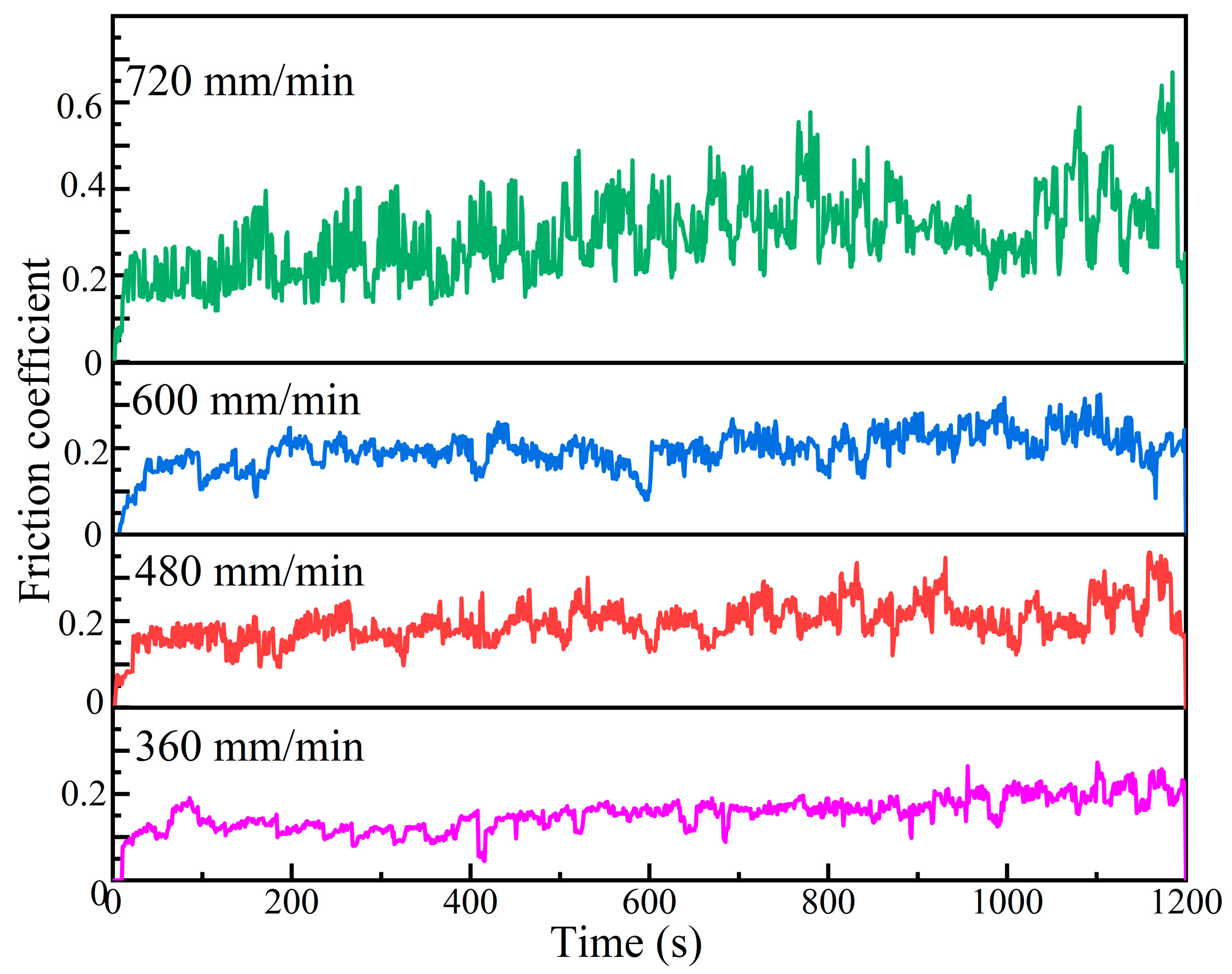
3.5. Effect of Laser Scanning Speed on Wear Resistance of Al-Ni Coatings

Figure 9 shows the friction coefficient curves of Al-Ni coatings under different scanning speeds. The average friction coefficients of coatings are 0.19, 0.24, 0.22 and 0.39 at the laser scanning speeds of 360 mm/min, 480 mm/min, 600 mm/min and 720 mm/min, respectively. At the early stage of the wear experiment, due to the rapid change in the contact area between the coating and the GCr15 grinding ball, the friction coefficient of each coating shows a rapid upward trend. As the wear experiment continues, the friction coefficients of coatings gradually stabilize at the laser scanning speeds of 360 mm/min, 480 mm/min and 600 mm/min. That is due to the following: On the one hand, the contact area between the grinding ball and the coatings does not change significantly, the contact pressure decreases and the wear process enters the stable stage [29]; on the other hand, the grains are relatively small and dense, and the oxide film is evenly distributed, which can reduce the further wear of coatings and improve their wear resistance [23]. However, at the laser scanning speed of 720 mm/min, due to the loose and coarse grains of the coating, the contact area changes continuously during the wear experiment, and the friction coefficient changes drastically.
The wear volumes of coatings and the substrate under different scanning speeds are illustrated in Figure 10. The average wear volumes of coatings are 0.64 mm3, 0.59 mm3, 0.53 mm3 and 0.56 mm3 at the laser scanning speeds of 360 mm/min, 480 mm/min, 600 mm/min and 720 mm/min, respectively. Compared to the substrate, the wear volume decreases by 40.08~51.38%. The minimum wear volume (0.53 mm3) is 49.62% of the substrate. The reason is that the hard phases (Al3Ni2 and Mg17Al12) in the coatings can improve their wear resistance [30]. At the early stage of the wear experiment, the softer part of the coating is first cut by the grinding ball. When the laser scanning speed is 600 mm/min, the microstructure of the coating is dense, fine and evenly distributed, meaning it plays a good skeleton support role. Therefore, the wear volume is the smallest at this time. However, when the laser scanning speed is 360 mm/min, due to the decrease in laser scanning speed, the degree of undercooling decreases, the nucleation rate decreases and the grains become coarse, which causes the support effect of grains to weaken.

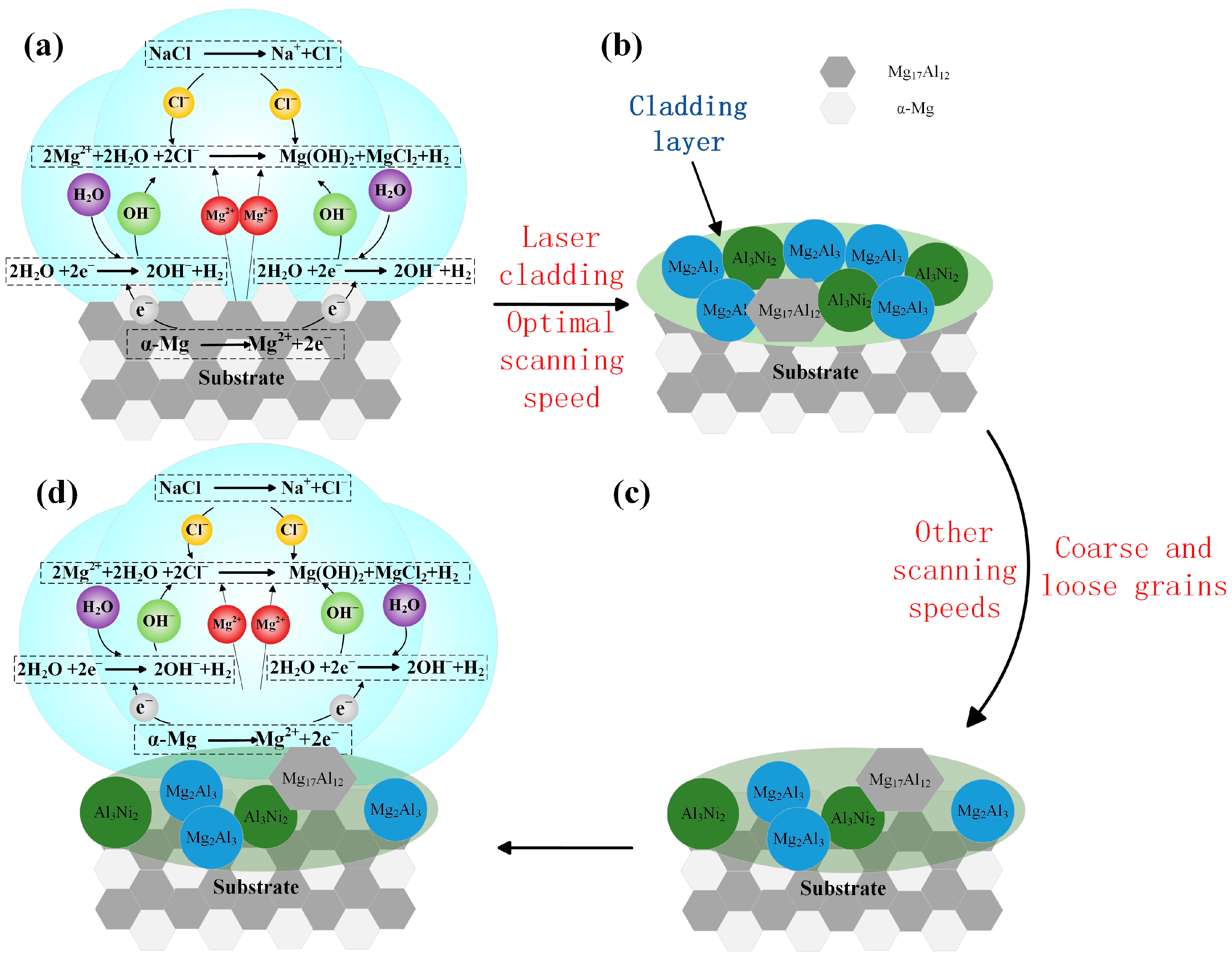
3.6. Effect of Laser Scanning Speed on Corrosion Resistance of Al-Ni Coatings

Figure 11 shows the polarization curves of Al-Ni coatings and Mg alloy substrate. From Figure 11, it can be seen that the corrosion resistance of coatings is stronger than that of the substrate. In addition, because the surface structure of the coating is composed of fine needle-like grains (Figure 7), this reduces the effective reaction area of the anode and cathode and causes the corrosion resistance of the coating to increase. This result is consistent with the literature [31,32]. When the laser scanning speed is 480 mm/min or 600 mm/min, the polarization curves have an obvious passive area, and they have better corrosion resistance. This is because the Al element in the coatings has formed a dense oxide film (Al2O3), which prevents further corrosion of the coatings. Therefore, with the increase in voltage, the change in current is not obvious during the corrosion experiment.
The anode and cathode slopes and corrosion current density were obtained by the Tafel extrapolation method, and the polarization resistance was calculated by the Stern–Geary equation (Equation (3)) [33]. The results are shown in Table 5.
i c o r r = B R P
where icorr represents the self-corrosion current density, and RP is the polarization resistance. B can be calculated by Equation (4) [33].
B = β a × β c 2.303 ( β a + β c )
where βa and βc are the anodic and cathodic Tafel constants.
As shown in Table 5, the self-corrosion potential results of the coatings under different scanning speeds were −1.29 V (360 mm/min), −0.955 V (480 mm/min), −0.918 V (600 mm/min) and −1.298 V (720 mm/min), respectively. Meanwhile, the self-corrosion current densities of the coatings were 3.548 × 10⁻³ A/cm2 (360 mm/min), 1.075 × 10⁻⁴ A/cm2 (480 mm/min), 1.261 × 10⁻⁴ A/cm2 (600 mm/min) and 2.587 × 10⁻³ A/cm2 (720 mm/min), respectively. When the laser scanning speed was 480 mm/min or 600 mm/min, the self-corrosion current density was one order of magnitude lower than that of the substrate (3.623 × 10⁻³ A/cm2). When compared with the substrate (−1.438 V), the self-corrosion potential increased by 0.483 V or 0.52 V, respectively. In addition, at the scanning speeds of 480 mm/min and 600 mm/min, the coatings had higher polarization resistance (387 Ω and 292 Ω, respectively), which indicates that the coatings have larger reaction resistance and higher corrosion resistance during the polarization reaction. However, the coatings at the scanning speeds of 360 mm/min and 720 mm/min had lower polarization resistance (10 Ω and 13 Ω, respectively). When compared with the Mg alloy substrate, the decrease in corrosion current density (still in the same order of magnitude as the substrate) and the increase in corrosion potential (0.148 V and 0.14 V, respectively) of the coatings were not obvious, and the corrosion resistance was not improved significantly. This was related to the coarse and loose structure of the coatings at the scanning speeds of 360 mm/min and 720 mm/min.
Figure 12 illustrates the corrosion mechanism of Al-Ni coatings and the substrate. As shown in Figure 12a, the structure of the substrate is composed of α-Mg and Mg17Al12 with a large potential difference; α-Mg with low self-corrosion potential is used as the anode and Mg17Al12 as the cathode during the corrosion process. The equations of electrochemical corrosion in solution are as follows:
Mg → Mg2+ + 2e (Anodic reaction)
2H2O + 2e → H2 + 2OH (Cathodic reaction)
Figure 12b illustrates the corrosion mechanism of Al-Ni coatings at the laser scanning speeds of 480 mm/min and 600 mm/min. Mg17Al12, Al3Ni2 and Mg2Al3 formed in the coatings have a lower potential difference, so the original electric pair (α-Mg and Mg17Al12) in the substrate are replaced, and the self-corrosion potential of coatings increases significantly [34,35]. In addition, grain refinement reduces the effective reaction area of the anode and cathode, which causes the corrosion resistance of coatings to increase.
When the laser scanning speed decreases to 360 mm/min, the laser specific energy increases, and the structure of the coating is coarse and loose. As shown in Figure 12c,d, during the corrosion process, α-Mg in the substrate is easily exposed to the corrosive liquid, and it becomes an electric pair with Mg17Al12 again, which reduces the corrosion resistance of the coating, and the self-corrosion current density increases slightly. At the laser scanning speed of 720 mm/min, from Figure 7d, it can be seen that the grains are coarse, and the grain boundary distance increases, which leads to the increase in the effective area of electrochemical corrosion and accelerates the speed of corrosion. Therefore, the coating has poor corrosion resistance.

4. Conclusions

  • At all laser scanning speeds, the morphological quality of coatings is good, the fish scale trajectory is obvious and there are no major defects. The coating is the smoothest at the laser scanning speed of 600 mm/min.
  • The coatings are composed of Al3Ni2, Mg17Al12 and Mg2Al3. The microstructure of Al-Ni coatings comprises dendrite crystals, and the grain size first decreases and then increases with the increase in the laser scanning speed.
  • The microhardness of Al-Ni coatings at different scanning speeds is 3.3~4.8 times that of the substrate. When the laser scanning speed is 600 mm/min, the average microhardness of the coating is the highest due to the effect of fine grain strengthening and dispersion strengthening. The wear volume of the coating is 49.62% of the matrix.
  • Because of the large amount of Al2O3 formed on the coating surface and the pairs with low potential difference during the corrosion experiment, the corrosion resistance of the coating is improved. When the laser scanning speed is 600 mm/min, the corrosion resistance of the coating is the best. The self-corrosion current density is one order of magnitude lower than that of the substrate, and the self-corrosion potential increases by 0.52 V. In addition, with the increase in laser scanning speed, the corrosion resistance of Al-Ni coatings first increases and then decreases.

Author Contributions

Conceptualization, Y.G.; Methodology, Y.G.; Validation, P.L.; Investigation, Y.G., P.L. and D.Z.; Resources, Y.G., P.L., S.B., D.Z. and M.J.; Data curation, P.L., S.B. and M.J.; Writing–original draft, S.J.; Writing–review & editing, S.J. All authors have read and agreed to the published version of the manuscript.

Funding

This work was supported by the Project of Science and Technology research of the Department of Education of Jilin Province (JJKH20240135KJ), and the Natural Science Foundation of the Science and Technology Department of Jilin Province (20230101335JC).

Data Availability Statement

The original contributions presented in the study are included in the article, further inquiries can be directed to the corresponding author.

Acknowledgments

Special thanks go to the Laser Laboratory of Northeast Electric Power University for the help with this study.

Conflicts of Interest

The authors declare no conflict of interest.

References

  1. Meng, G.Y.; Protasova, N.A.; Kruglov, E.P.; Lin, X.; Ding, X. Solidification behavior and morphological evolution in laser surface forming of AlCoCrCuFeNi multi-layer high-entropy alloy coatings on AZ91D. J. Alloys Compd. 2019, 772, 994–1002. [Google Scholar] [CrossRef]
  2. Mao, P.; Wang, J.X.; Bai, S.; Liu, Z.Y. Effects of ultrasonic treatment on the microstructures and hardening of Al–Cu–Mg–Ag alloys. J. Mater. Res. Technol. 2024, 30, 6064–6067. [Google Scholar] [CrossRef]
  3. Wang, S.; Pan, H.C.; Xie, D.S.; Zhang, D.D.; Li, J.R.; Xie, H.B. Grain refinement and strength enhancement in Mg wrought alloys: A review. J. Magnes. Alloy. 2023, 11, 4128–4145. [Google Scholar] [CrossRef]
  4. Yang, L.Q.; Li, Z.Y.; Zhang, Y.Q.; Wei, S.Z.; Wang, Y.J.; Kang, Y. In-situ TiC-Al3Ti reinforced Al-Mg composites with Y2O3 addition formed by laser cladding on AZ91D. Surf. Coat. Technol. 2020, 383, 125249. [Google Scholar] [CrossRef]
  5. Pei, X.L.; Li, Z.Y.; Zhang, Y.Q.; Wei, S.Z.; Yang, L.Q.; Wang, Y.J. A gradient Al/Ni-Cr-Al layer formed by direct current pulse metal inert gas welding combined laser cladding on AZ91D magnesium alloy. Vacuum 2019, 165, 86–95. [Google Scholar] [CrossRef]
  6. Zhang, Z.B.; Kim, J.Y.; Li, M.; Gao, Y.; Hu, Y.B.; Jiang, B.; Pan, F.S. Effects of Nd content on the microstructures and mechanical properties of ZK60 Mg alloy and corresponding strengthening mechanisms. Mater. Sci. Eng. A-Struct. 2024, 901, 146504. [Google Scholar] [CrossRef]
  7. Song, Y.W.; Dai, J.M.; Sun, S. A comparative study on the corrosion behavior of AZ80 and EW75 Mg alloys in industrial atmospheric environment. Mater. Today 2024, 38, 108263. [Google Scholar] [CrossRef]
  8. Wen, X.; Cui, X.F.; Jin, G.; Jiao, Y.L.; Fang, Y.C. A novel Ni2MnCuSnAl0.1 multi-principal element alloy coating to enhance the wear resistance and corrosion resistance of Mg-Li alloy. Opt. Laser Technol. 2021, 142, 107243. [Google Scholar] [CrossRef]
  9. Wu, M.J.; Wu, F.F.; Long, M.J.; Ye, P.C.; Jiang, F.; Jiang, J.Y. Effect of oxidation treatment on the structure and composition of oxide film on Al-Mg-Sc alloy surface and microstructure of Al substrate near interface. Mater. Lett. 2022, 325, 132819. [Google Scholar] [CrossRef]
  10. Liu, Y.R.; Zhang, K.M.; Zou, J.X.; Yan, P.; Zhang, X.; Song, L.X. Microstructure and property modifications in surface layers of a Mg-4Sm-2Al-0.5Mn alloy induced by pulsed electron beam treatments. J. Magnes. Alloy. 2021, 9, 216–224. [Google Scholar] [CrossRef]
  11. Dong, F.; Peng, X.Q.; Lai, T.; Guan, C.L.; Li, G.H.; Liu, J.F.; Dai, Y.F. Improving the surface quality and its mechanism in ultraprecision machining of Al–Mg–Si alloy by multiple high energy shot peening pretreatment. J. Mater. Res. Technol. 2024, 30, 7051–7064. [Google Scholar] [CrossRef]
  12. Mohammadreza, D.; Hamid, R.B.; Abbas, S.; Mahmood, R.; Ashish, K.K.; Seeram, R.; Pradeep, L.M.; Manoranjan, M.; Ahmad, F.I.; Safian, S.; et al. Surface modification of magnesium alloys using thermal and solid-state cold spray processes: Challenges and latest progresses. J. Magnes. Alloy. 2022, 10, 2025–2061. [Google Scholar]
  13. Mohammad, D.; Pang, X.; Hamid, J. The effect of pure aluminum cold spray coating on corrosion and corrosion fatigue of magnesium (3% Al-1% Zn) extrusion. Surf. Coat. Technol. 2017, 309, 423–435. [Google Scholar]
  14. Usman, A.; Lui, Y.; Lu, F.F.; Muhammad, Y.; Li, C.J.; Li, C.X. Enhancement of Corrosion Resistance and Tribological Properties of LA43M Mg Alloy by Cold-Sprayed Aluminum Coatings Reinforced with Alumina and Carbon Nanotubes. J. Therm. Spray Technol. 2021, 30, 668–679. [Google Scholar]
  15. Su, Y.P.; Yue, T.M. Microstructures of the bonding area in laser cladded Zr-based amorphous alloy coating on magnesium. Mater. Today Commun. 2020, 25, 101715. [Google Scholar] [CrossRef]
  16. Tan, C.L.; Zhu, H.M.; Kuang, T.C.; Shi, J.; Liu, H.W.; Liu, Z.W. Laser cladding Al-based amorphous-nanocrystalline composite coatings on AZ80 magnesium alloy under water cooling condition. J. Alloys Compd. 2017, 690, 108–115. [Google Scholar] [CrossRef]
  17. Cen, L.; Du, W.; Gong, M.C.; Lu, Y.; Zhang, C.; Gao, M. Effect of high-frequency beam oscillation on microstructures and cracks in laser cladding of Al-Cu-Mg alloys. Surf. Coat. Technol. 2022, 447, 128852. [Google Scholar] [CrossRef]
  18. Li, N.; Wei, Z.T.; Zhao, W.J.; Yan, S.; Liu, D.Z.; Jiao, Q.J. Improved ignition and combustion performance of Al-Zn-Mg ternary alloys by incorporating Mg into Al-Zn alloys. Chem. Eng. J. 2024, 494, 153237. [Google Scholar] [CrossRef]
  19. Yamasaki, M.; Shi, Z.; Atrens, A.; Furukawa, A.; Kawamura, Y. Influence of crystallographic orientation and Al alloying on the corrosion behaviour of extruded α-Mg/LPSO two-phase Mg-Zn-Y alloys with multimodal microstructure. Corros. Sci. 2022, 200, 110237. [Google Scholar] [CrossRef]
  20. Zhang, X.L.; Zhang, K.M.; Zou, J.X. Microstructures and properties in surface layers of Mg-6Zn-1Ca magnesium alloy laser-clad with Al-Si powders. Trans. Nonferr. Metal. Soc. 2018, 28, 96–102. [Google Scholar] [CrossRef]
  21. Lei, Y.W.; Sun, R.L.; Tang, Y.; Niu, W. Experimental and thermodynamic investigations into the microstructure of laser clad Al–Si coatings on AZ91D alloys. Surf. Coat. Technol. 2012, 207, 400–405. [Google Scholar] [CrossRef]
  22. Wan, S.M.; Cui, X.F.; Jin, G.; Ma, J.J.; Yang, Y.Y.; Liu, K.J.; Li, J.; Wang, S.; Wang, J.Y. Microstructure and properties characterization of laser-cladded Cu-Al alloy coatings on Mg-Li alloy. Surf. Coat. Technol. 2023, 460, 129430. [Google Scholar] [CrossRef]
  23. Gao, Y.L.; Wang, C.S.; Pang, H.J.; Liu, H.B.; Yao, M. Broad-beam laser cladding of Al–Cu alloy coating on AZ91HP magnesium alloy. Appl. Surf. Sci. 2007, 253, 4917–4922. [Google Scholar] [CrossRef]
  24. Nie, M.H.; Zhang, S.; Wang, Z.Y.; Zhang, C.H.; Chen, H.T.; Chen, J. Effect of laser power on microstructure and interfacial bonding strength of laser cladding 17-4PH stainless steel coatings. Mater. Chem. Phys. 2022, 275, 125236. [Google Scholar] [CrossRef]
  25. He, C.Y.; Du, Y.; Chen, H.L.; Ouyang, H.W. Measurement of the isothermal sections at 700 and 427 °C in the Al–Mg–Ni system. Int. J. Mater. Res. 2008, 99, 907–911. [Google Scholar] [CrossRef]
  26. Gan, Z.T.; Yu, G.; He, X.L.; Li, S.X. Numerical simulation of thermal behavior and multicomponent mass transfer in direct laser deposition of Co-base alloy on steel. Int. J. Heat. Mass. Tran. 2017, 104, 28–38. [Google Scholar] [CrossRef]
  27. Gao, Y.L.; Xiong, D.S.; Wang, C.S.; Chen, Y.Z. Influences of laser powers on microstructure and properties of the coatings on the AZ91HP magnesium alloy. Acta Metall. Sin.-Engl. Lett. 2009, 22, 167–173. [Google Scholar] [CrossRef]
  28. Guo, W.; Zhang, Y.P.; Hu, L.; Li, Y.K. Microstructure and mechanical properties laser cladding 304 stainless steel. Appl. Laser 2019, 39, 191–197. [Google Scholar]
  29. Luo, X.X.; Cao, J.; Meng, G.H.; Chuan, Y.Y.; Yao, Z.J.; Xie, H. Systematical investigation on the microstructures and tribological properties of Fe-Al laser cladding coatings. Appl. Surf. Sci. 2020, 516, 146121. [Google Scholar] [CrossRef]
  30. Zheng, B.J.; Chen, X.M.; Lian, J.S. Microstructure and wear property of laser cladding Al+SiC powders on AZ91D magnesium alloy. Opt. Laser Eng. 2010, 48, 526–532. [Google Scholar] [CrossRef]
  31. Taltavull, C.; Torres, B.; Lopez, A.J.; Rodrigo, P.; Otero, E.; Atrens, A.; Rams, J. Corrosion behaviour of laser surface melted magnesium alloy AZ91D. Mater. Des. 2014, 57, 40–50. [Google Scholar] [CrossRef]
  32. Bu, R.; Jin, A.X.; Sun, Q.; Zan, W.; He, R.L. Study on laser cladding and properties of AZ63-Er alloy for automobile engine. J. Mater. Res. Technol. 2020, 9, 5154–5160. [Google Scholar] [CrossRef]
  33. Sun, Y.P.; Yang, C.T.; Yang, C.G.; Xu, D.K.; Li, Q.; Yin, L.; Qiu, C.S.; Liu, D.; Yang, K. Stern–Geary Constant for X80 Pipeline Steel in the Presence of Different Corrosive Microorganisms. Acta Metall. Sin.-Engl. Lett. 2019, 32, 1483–1489. [Google Scholar] [CrossRef]
  34. Sun, F.Z.; Li, X.X.; Zheng, K.Y.; Bo, H.; Li, Y.; Zang, Y.; Pang, M. Study on the Influence of Graphene Content Variation on the Microstructure Evolution and Properties of Laser Additive Manufacturing Nickel-Based/SiC Composite Cladding Layer on Aluminum Alloy Surface. Materials 2022, 15, 8219. [Google Scholar] [CrossRef] [PubMed]
  35. Gao, Y.L.; Wang, C.S.; Lin, Q.; Liu, H.B.; Yao, M. Broad-beam laser cladding of Al–Si alloy coating on AZ91HP magnesium alloy. Surf. Coat. Technol. 2006, 201, 2701–2706. [Google Scholar] [CrossRef]
Figure 1. Microstructure of AZ91HP Mg alloy: (a) Primary α-Mg; (b) Eutectic α-Mg and divorced eutectic β-Mg17Al12.
Processes 12 01689 g001
Figure 2. The macroscopic morphology of Al-Ni coatings under different scanning speeds: (a) 360 mm/min; (b) 480 mm/min; (c) 600 mm/min; (d) 720 mm/min.
Processes 12 01689 g002
Figure 3. The XRD spectrum of Al-Ni coatings under different scanning speeds.
Processes 12 01689 g003
Figure 4. (af) The cross-sectional microstructure and map scanning results of Al-Ni coating at a scanning speed of 600 mm/min.
Processes 12 01689 g004
Figure 5. (af) Microstructure and EDS of the coating with a scanning speed of 600 mm/min.
Processes 12 01689 g005
Figure 6. (af) The point scanning results for Al-Ni coating.
Processes 12 01689 g006
Figure 7. The top microstructure of Al-Ni coatings under different scanning speeds: (a) 360 mm/min; (b) 480 mm/min; (c) 600 mm/min; (d) 720 mm/min.
Processes 12 01689 g007
Figure 8. The microhardness distribution curves of Al-Ni coatings under different scanning speeds.
Processes 12 01689 g008
Figure 9. The friction coefficient curves of Al-Ni coatings under different scanning speeds.
Processes 12 01689 g009
Figure 10. The wear volumes of coatings and substrate under different scanning speeds.
Processes 12 01689 g010
Figure 11. The polarization curves of Al-Ni coatings and Mg alloy substrate.
Processes 12 01689 g011
Figure 12. The corrosion mechanism of Al-Ni coatings and the substrate (ad).
Processes 12 01689 g012
Table 1. Chemical composition of AZ91HP (wt. %).
ElementAlZnMnSiFeCuNiBeMg
Mass percentage8.89000.56200.20410.04430.00300.00340.00900.0012Bal.
Table 2. Chemical composition of Al-Ni powders.
ElementAlNi
Mass percentage (wt. %)64.835.2
Table 3. Laser process parameters of Al-Ni coatings.
Laser Power (W)Scanning Speed (mm/min)Overlap Rate (%)Laser Spot Diameter (mm)Argon Flow Rate (L/min)
9003603035
9004803035
9006003035
9007203035
Table 4. The average grain size of Al-Ni coatings under different scanning speeds.
Scanning Speed (mm/min)Diffraction IntensityPeak Width at Half HeightGrain Size (nm)
3605840.59114.3
4802530.65013.0
6002210.69712.1
7202920.61213.8
Table 5. Corrosion parameters of coatings under different scanning speeds in 3.5 wt. % NaCl solution.
CoatingEcorr (V)Icorr (A/cm2)Cathodic SlopeAnodic SlopeRp (Ω)
360 mm/min−1.293.548 × 10−35.8756.33110
480 mm/min−0.9551.075 × 10−46.8763.564387
600 mm/min−0.9181.261 × 10−49.5412.262292
720 mm/min−1.2982.587 × 10−38.0685.24713
Mg alloy−1.4383.623 × 10−33.3365.14914
Disclaimer/Publisher’s Note: The statements, opinions and data contained in all publications are solely those of the individual author(s) and contributor(s) and not of MDPI and/or the editor(s). MDPI and/or the editor(s) disclaim responsibility for any injury to people or property resulting from any ideas, methods, instructions or products referred to in the content.

