Article

Overview of Salt Cavern Oil Storage Development and Site Suitability Analysis

1
College of energy engineering, Xi’an University of Science and Technology, Xi’an 710054, China
2
Institute of Rock and Soil Mechanics, Chinese Academy of Sciences, Wuhan 430071, China
*
Author to whom correspondence should be addressed.
Processes 2024, 12(8), 1709; https://doi.org/10.3390/pr12081709
Submission received: 17 July 2024 / Revised: 7 August 2024 / Accepted: 7 August 2024 / Published: 14 August 2024
(This article belongs to the Section Energy Systems)

Abstract

:
Salt cavern storage, characterized by its safety, stability, large scale, economic viability, and efficiency, stands out as a cost-effective and relatively secure method for large-scale petroleum reserves. This paper provides an overview of the current development status of salt cavern storage technologies both domestically and internationally, analyzes the advantageous conditions and numerous challenges faced by salt cavern Strategic Petroleum Reserve (SPR) storage in China, and forecasts the development trends of this technology. The conclusions indicate that China possesses all of the necessary conditions for the development of salt cavern storage. Moreover, utilizing the Analytical Hierarchy Process (AHP), a macro suitability hierarchical evaluation system is constructed for the site selection and construction of salt cavern storage facilities. This system quantifies various site selection indicators, integrating expert opinions and findings from relevant theoretical research to establish grading standards for the suitability indices of salt cavern storage construction. Applied to the site evaluation of salt cavern storage at the Jintan Salt Mine in Jiangsu, the results indicate its high suitability for storage construction, making it an ideal location for establishing such facilities. The evaluation results are consistent with expert opinions, demonstrating the rationality of this method.

1. Introduction

Oil is a vital strategic resource for ensuring the smooth development of the national economy. Guaranteeing the oil supply is important for maintaining social stability and economic growth. Currently, China’s dependency on foreign oil continues to grow, having exceeded 70% for four consecutive years, creating a severe energy security situation, as shown in Figure 1 [1]. As China’s oil consumption and imports keep rising and the gap between China’s oil reserves and the 90-day safety strategic reserve recommended by the International Energy Agency remains substantial, the existing oil storage facilities cannot meet the demand. Therefore, there is an urgent need to build large-scale oil reserve facilities in the short term.
The commonly used methods for oil storage include offshore oil depots, surface storage tanks, and deep underground storage [2,3,4,5]. Offshore oil depots are expensive to construct and technically complex, with a high risk of leakage that could severely damage the marine environment [6]. Surface storage tanks occupy large areas and are costly. They are typically located in coastal regions for easy access to oil tanker terminals, but this method carries significant safety risks. In contrast, underground oil storage is deeply buried, effectively avoiding damage from natural disasters, fires, warfare, and terrorist attacks, making it highly suitable for strategic defense [7,8]. Salt rock has low porosity, is nearly impermeable, and possesses excellent rheological properties. It plays a significant role in storing waste in the form of paste backfill, which can limit the surface storage of waste energy [9,10]. It is internationally recognized as an excellent site for underground strategic oil reserves and holds a prominent position in oil storage [11,12].
China’s current methods of using surface storage tanks and underground water-sealed caverns for oil reserves are much more expensive than salt cavern storage. Globally, underground salt cavern storage facilities are primarily found in the United States, France, Germany, Canada, and other Western countries. Since the 1960s, some foreign salt cavern storage facilities have gradually been put into operation, and there are now over 70 active salt cavern storage sites worldwide [13]. China has abundant salt cavern resources, with an existing capacity of approximately 130 million cubic meters, most of which have good sealing properties after cavity creation. However, only about 40 salt caverns are currently utilized, accounting for just 0.2% of the total, leaving a vast amount of underground salt cavern resources untapped. With its abundant salt cavern resources, China must establish underground salt cavern oil reserves to normalize its oil storage levels.
Currently, there are few articles on the development of salt cavern storage in China, and those that exist are relatively outdated. Chinese scholars mainly focus on three aspects of strategic oil reserve research: demonstrating the necessity of establishing strategic oil reserves, summarizing and synthesizing the experiences and lessons learned from developed countries, and determining the scale of strategic oil reserves [14]. This paper starts with the current development status both domestically and internationally, providing a relatively comprehensive discussion of the advantages of China’s salt cavern storage technology and resources, as well as the key issues and numerous challenges faced. Additionally, this paper constructs a hierarchical structure model for the macro-suitability assessment of salt cavern storage site selection and construction based on the Analytic Hierarchy Process. It proposes a macro-suitability assessment method for site selection and the construction of storage caverns in different stratified salt rock formations in China. This method is applied to the site selection and evaluation of the salt cavern storage in Jintan Salt Mine, Jiangsu. The results show that the Jintan Salt Mine has a high suitability for storage cavern site selection, making it an ideal location for building a storage facility. This research fills a gap in China’s salt cavern storage site selection evaluation system and provides a reference for the development of domestic salt cavern storage technology.

2. Current Status of Oil Storage Development in Salt Caverns at Home and Abroad

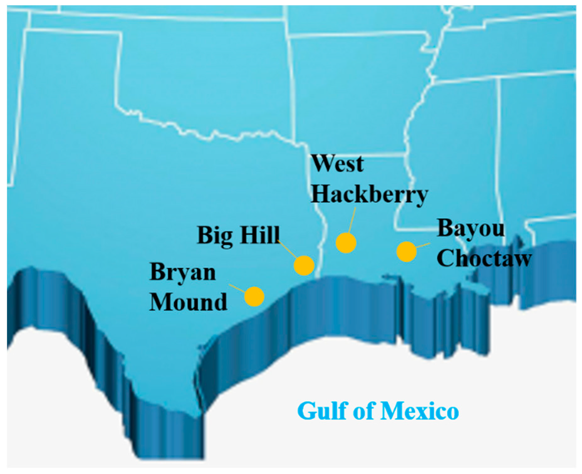
2.1. Current Situation of Salt Cavern Oil Storage Development in Foreign Countries

Salt cavern oil storage has become an important method for many countries to implement strategic petroleum reserves, primarily to compensate for the shortcomings of surface oil storage in terms of construction costs, safety, and storage capacity. Currently, the countries utilizing salt caverns are mainly concentrated in North America and Europe [15]. The United States has constructed five strategic reserve bases along the Gulf of Mexico coast in Texas and Louisiana, as shown in Figure 2, with a total storage capacity of 1.1 × 10 8 cubic meters. These include the Bryan Mound ( 3.5 × 10 7 cubic meters) and Big Hill ( 2.5 × 10 7 cubic meters) bases in Texas, and the West Hackberry ( 3.5 × 10 7 cubic meters), Bayou Choctaw ( 1.2 × 10 7 cubic meters), and Weeks Island ( 1.1 × 10 6 cubic meters) bases in Louisiana [16]. Each reserve base consists of a varying number of salt caverns, with the caverns typically being about 250 m high and 70 m in diameter. The U.S. oil reserves are divided into three main systems: the Seaway system, the Texoma system, and the Capline system. Each system is composed of reserve facilities, pipeline transit stations, refining centers, and oil pipelines [17,18].
In Germany, underground reserve facilities are distributed roughly from north to south, with a higher concentration in the northwest region. Oil is stored in each federal state according to regional and demand-based principles. The majority of salt cavern reserves are used to store crude oil and refined products such as gasoline and diesel. There are four main oil storage bases in Germany, comprising a total of 58 caverns: Rüstringen with 35 caverns (including nine strategic reserves), Sottorf with 9 caverns (strategic reserves), Heide with 9 caverns (strategic reserves), and Lesum with 5 caverns (strategic reserves), with a total storage capacity of 1.0 × 10 7 cubic meters [19].
France is the first country in the world to establish a corporate oil reserve system. Unlike the United States and Germany, France’s strategic petroleum reserves are not primarily focused on crude oil, but also include automotive gasoline, aviation kerosene, diesel, heating oil, illuminating kerosene, jet fuel, heavy oil, and liquefied petroleum gas. The Manosque salt cavern reserve is located near the town of Manosque, southeast of Marseille. Construction began in 1968, and currently, there are 28 caverns, with 14 used for crude oil storage and 14 for various refined products, storing a total of 8.17 million cubic meters. The cavern volumes range from 200,000 to 500,000 cubic meters, accounting for 40% of France’s national strategic reserves [20].
The advanced experience of foreign countries in constructing strategic petroleum reserves provides valuable lessons for building and improving China’s strategic petroleum reserve system [21]. However, due to significant differences in geographical conditions between China and other countries, many factors need to be considered in specific operations.

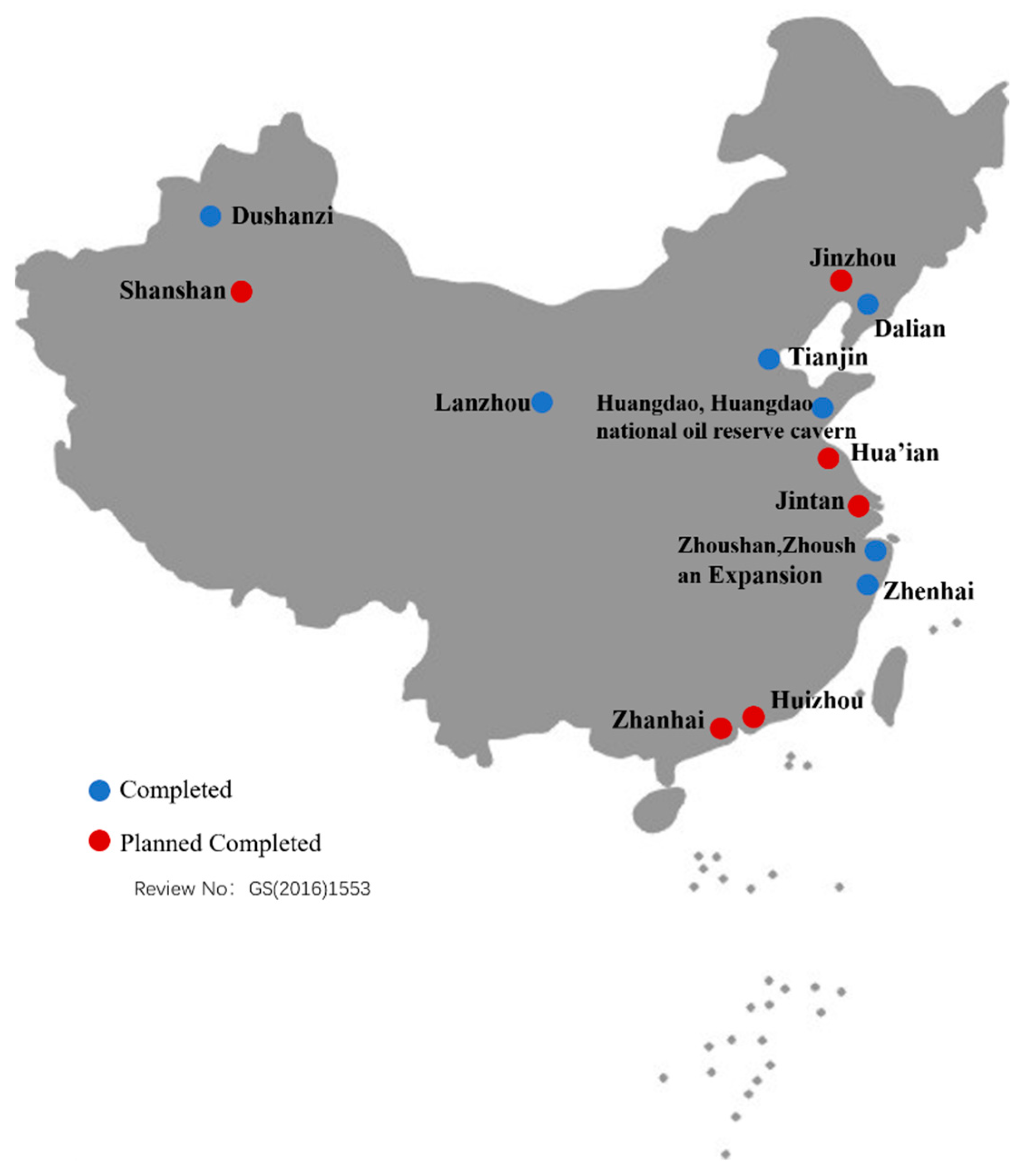
2.2. Development Status of Domestic Salt Cavern Oil Storage

China is rich in salt mine resources, but the history of using salt caverns for energy storage spans only a few decades. In 2003, the Chinese government officially approved the establishment of national strategic petroleum reserves, planning a total reserve capacity of 500 million barrels (approximately 68 million tons), with an estimated total investment of about RMB 100 billion. The plan is divided into three phases, to be completed over three five-year plans within 15 years. The reserve arrangement includes 12–20 million tons for the first phase, 28 million tons for the second phase, and 28 million tons for the third phase [22]. Currently, the third phase proposes establishing large-scale oil storage in salt caverns, with the Dingyuan, Zhaoji, and Zhoutian salt caverns as potential sites [23].
China has completed a total of nine national oil reserve bases, as shown in Figure 3, eight of which are surface storage bases located in Zhoushan, Zhoushan Expansion, Zhenhai, Dalian, Huangdao, Dushanzi, Lanzhou, and Tianjin, with total storage capacities of 5 million, 2.5 million, 5.2 million, 3 million, 3.2 million, 3 million, 3 million, and 3.2 million cubic meters, respectively. There is one underground storage base, the Huangdao national oil reserve cavern, with a storage capacity of 3 million cubic meters [16]. These nine national oil reserve bases and some social reserves can store a total of 3325 × 10 4 t of crude oil, as shown in Table 1 [24]. The National Energy Reserve Center is advancing the construction of the Jintan and Huai’an salt cavern oil reserves [25].
Most of China’s national oil reserve bases are located in coastal areas and primarily use above-ground storage, which has weak resistance to attacks and can easily become targets for military or terrorist strikes. Most of China’s national strategic oil reserve bases are located in coastal areas and primarily consist of above-ground storage, which has weak resistance to attacks, and can easily become targets for military or terrorist attacks. Due to the unknown changes in the pore permeability and mechanical properties of salt rock layers under oil–water erosion, these uncertainties may pose a greater threat to the long-term safe operation of storage facilities. Several significant disasters abroad have occurred due to cavern failures, with accidents caused by the leakage of storage media accounting for 60% of total incidents in salt cavern energy storage. For instance, in 2001, the Yaggy storage facility in the USA and in 2004, the Moss Bluff storage facility experienced oil and gas leakage due to cavern damage, leading to seal failure. Additionally, in 2001, the Fort Saskat storage facility in Canada and in 1918, the West Hackberry storage facility in the USA suffered oil and gas leakage due to uneven deformation of the overlying strata, which caused seal failure [26]. Considering the need to ensure oil security, reduce construction costs, and promote coordinated regional economic development, the shift from above-ground to underground national oil reserves is an inevitable trend.

3. Overview of the Development of Salt Cavern Oil Storage in China

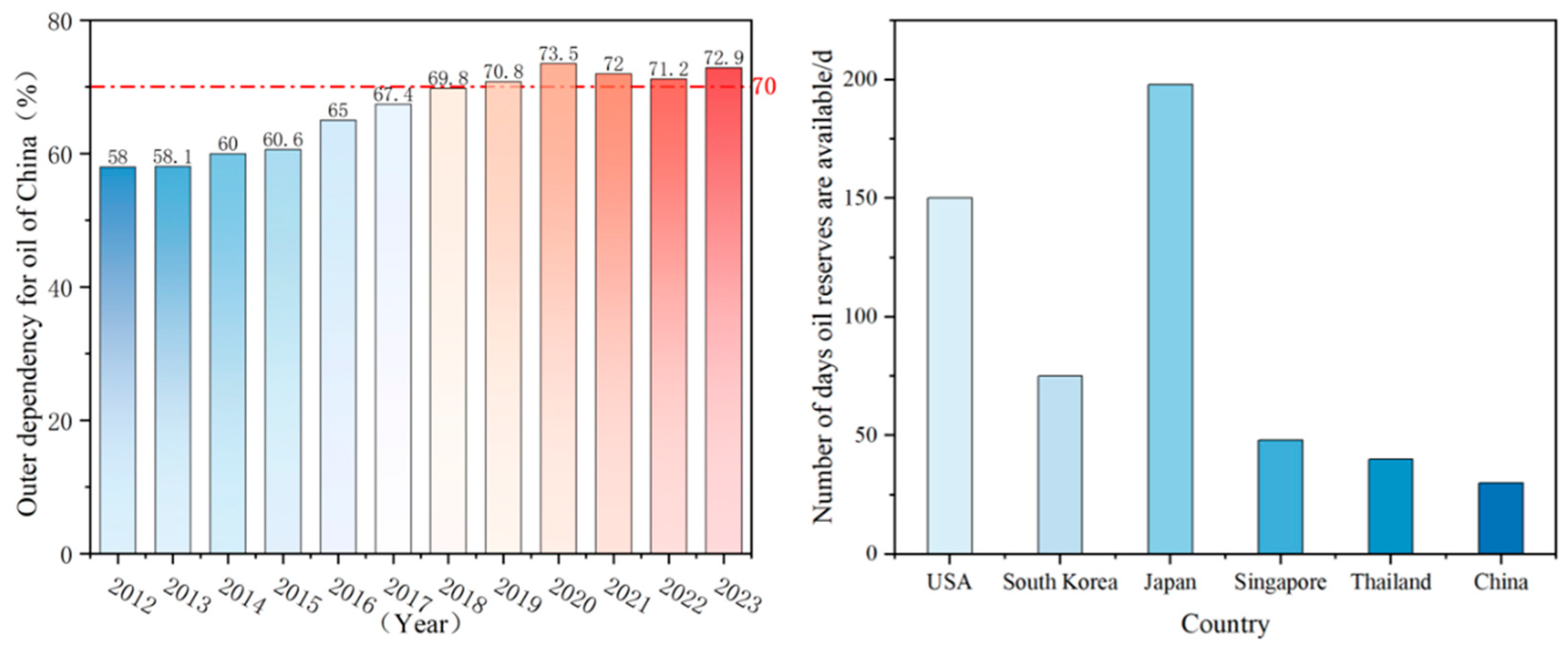
3.1. Advantages of China’s Salt Cavern Storage for Strategic Petroleum Reserves

3.1.1. Technical Advantages

The construction of underground salt cavern storage facilities in China is still in the preliminary feasibility analysis stage. However, the underground gas storage project associated with the West-to-East Gas Pipeline at the Jintan salt mine began operation in 2007 and has been operating safely and steadily ever since. Additionally, the underground gas storage project for the Sichuan-to-East Gas Transmission is currently under construction. These developments strongly validate the feasibility of strategic oil and gas reserves in China’s layered salt rock formations and establish a solid technical foundation for such projects [27,28]. Although there are significant differences in the physical properties of oil and natural gas, the site selection, construction, and operational management of salt caverns are fundamentally similar. Furthermore, oil storage caverns have relatively lower requirements for the sealing and stability of salt caverns compared to gas storage caverns, making their construction easier [29].
In addition, China’s salt rock resources mostly consist of lacustrine depositional stratified salt rocks (with a thickness generally less than 200 m), differing from the thick marine depositional salt domes found in other countries (with thicknesses ranging from several hundred meters to over a thousand meters). The basic characteristics of these stratified salt rocks include multiple thin layers and numerous insoluble interlayers within the salt-bearing formations, leading to complex engineering geological structures and rock mechanics properties [30,31]. While foreign oil and gas storage facilities are typically constructed in single salt domes, China’s facilities must be built in stratified salt rocks [32].
Given these unique geological conditions, Chinese scholars have conducted extensive foundational research, including the precise detection of salt layers for proposed storage sites, analysis of storage stability and sealing, multi-interlayer solution cavity creation and repair technology, ultra-fine cement plugging for micro-permeable layers, catastrophic evolution of dense storage groups, and risk assessment [33,34,35,36,37,38]. These research outcomes provide critical technical support for the site selection, design, construction, and stable operation of China’s stratified salt rock underground storage facilities, accumulating valuable technology and experience for the construction of China’s stratified salt rock underground strategic petroleum reserves.

3.1.2. Resource Advantages

China possesses abundant well and mineral salt resources. As one of the world’s largest salt producers, China ranks first globally in the production of sea salt from seawater. The combined production of sea salt, lake salt, and well-mineral salt ranks second in the world, following the United States. According to geological research and exploration work, by the end of 1996, China’s proven reserves of NaCl amounted to over 400 billion tons, widely distributed across 17 provinces (or autonomous regions). The main salt deposits in China, which are from the Cretaceous and Tertiary periods, are the primary targets for domestic development. These deposits are mostly buried at depths ranging from 500 to 1500 m. Based on international experience, this depth range is considered ideal for constructing salt cavern storage facilities in China. In 2014, the national production of raw salt was 90.78 million tons, with well-mineral salt production at 48.32 million tons, accounting for more than half of the total raw salt production. Based on the estimated production of well-mineral salt, more than 20 million cubic meters of underground salt cavern space can be generated annually [39]. Additionally, the net volume of newly added underground salt cavern space exceeds 5 million cubic meters annually. The annual storage capacity of rock salt bodies continues to increase, providing abundant old caverns suitable for the construction of oil reserves [40,41]. Among the underground salt mines exploited in the past decade, many have the potential to be directly converted into underground oil storage caverns. If these conversions are successful, they will significantly accelerate China’s strategic petroleum reserve process.

3.1.3. Transportation Advantages

China has established a dense and comprehensive oil transportation pipeline network. In 2004, the national oil transportation pipeline mileage was short, thus only considering building storage facilities in coastal areas convenient for tanker docking. With the rapid development of China’s oil and gas pipeline network, oil transportation pipelines are no longer a restrictive issue. From 2007 to 2021, China’s crude oil pipelines increased from 17,000 km to 31,000 km, and refined oil pipelines increased from 12,000 km to 30,000 km. According to surveys, multiple oil pipelines can be found within a 100 km radius of salt mines in the central and eastern regions of China.

3.2. Key Issues and Development Trends in China’s Strategic Petroleum Reserves

Since there is no precedent for constructing salt cavern storage for oil in China, and due to the lack of practical experience, it is necessary to study and tackle the key technologies required for building salt cavern storage facilities. This should be based on foreign experiences and adapted to China’s specific geological conditions and the current state of rock salt resource development. Specifically, the following three aspects need to be addressed:
Establishing methods and standards for screening existing cavities: Currently, China has a large number of existing cavern resources. Utilizing these existing cavities for oil storage conversion is more economical than creating new ones. However, these cavities vary greatly in shape. Determining the safe pillar distance and the appropriate shape for oil storage requires screening methods and standards [42,43,44].
Engineering technology for converting oil storage caverns: Crude oil contains corrosive impurities that can corrode injection and production tubing, such as inorganic salts, sulfides, sulfur dioxide, and water. Additionally, the high concentration of chloride ions in brine accelerates corrosion. The stability of mudstone interlayers or cap rocks may also change when exposed to storage media. Determining the appropriate well structure to meet the functional requirements of oil storage caverns is crucial for construction quality and ensuring the storage facility can function effectively when needed.
Injection and production operation technology for salt cavern storage: To maximize the functionality of constructed oil storage caverns, it is essential to manage the relationship between injection/production rates and cavity stability, maintain cavity stability at low pressures, and prevent crystallization blockages in the tubing due to contact with brine [45].
The construction of salt cavern storage for oil in China is in its early stages, facing numerous challenges. It is essential to recognize the strategic importance of salt cavern storage for China’s oil reserves, and assimilate and absorb foreign advanced experiences and technologies [46]. In the long term, when building strategic oil reserves, China should prioritize salt cavern storage by learning from advanced foreign experiences and technologies. Notable projects abroad that can serve as references include the United States’ Strategic Petroleum Reserve in the Gulf of Mexico, which is the world’s largest emergency oil storage facility and includes multiple salt caverns; Germany’s Etzel storage facility, one of the country’s largest underground oil storage sites, capable of storing crude oil and natural gas; and France’s Manosque underground oil storage facility, which is designed to ensure rapid response capabilities in emergencies. Although China has developed the technical capability to construct gas storage facilities in ultra-thin multi-interlayer salt caverns, challenges such as low cavity creation efficiency, complex old cavity conversion, and a lack of suitable salt mines for gas storage remain. Key research areas include precise measurement technology for salt cavities, volume control technology, environmentally friendly and energy-efficient cavity creation technology, and cavity creation technology under complex geological conditions [47,48,49,50]. Overall, China’s current salt cavern construction process is not yet perfected and lacks a rational, efficient construction system. The future development of China’s salt cavern energy storage facilities will face both opportunities and challenges [51].

4. Construction of Salt Cavern Oil Storage and Principles and Factors for Site Selection

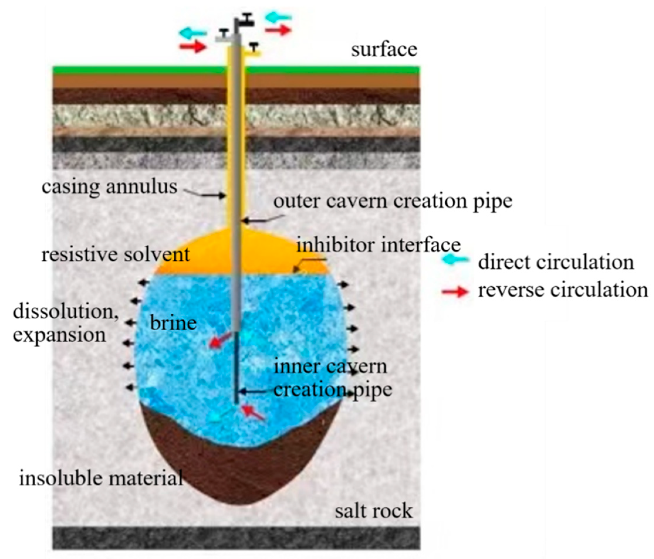
4.1. Construction of Salt Cavern Oil Storage

Salt cavern storage facilities are generally constructed in deep underground salt mines using the “solution mining” method. This technique often involves single-well cavern creation, as exemplified by the Jintan salt cavern storage [52]. Solution mining involves drilling a well to connect the salt rock layers, which are buried several hundred to thousands of meters deep, with the surface and installing casing. Two concentric pipes are then placed within the casing: the smaller diameter pipe is called the central pipe, and the larger diameter pipe is called the intermediate pipe [53]. Freshwater is continuously injected into the salt layer through the central pipe and the annular space between the two pipes. The salt rock dissolves, and the brine is discharged, creating and gradually expanding a cavity, as shown in Figure 4.
Solution mining can be classified into direct circulation and reverse circulation methods based on the injection and extraction modes. In “direct” circulation, the injection point is below the extraction point, meaning freshwater is injected through the central pipe (cavern creation inner pipe) and discharged through the intermediate pipe (casing annulus). In “revers” circulation, the injection point is above the extraction point, meaning freshwater is injected through the intermediate pipe and discharged through the central pipe. The proper utilization of both direct and reverse circulation can effectively increase the cavern creation rate and better control the cavity shape. Inhibitors are materials with a density lower than water and insoluble in salt rock, floating on the brine. The density difference between the inhibitor and the brine forms a protective layer at the top of the cavity, preventing the dissolution of the roof and promoting the lateral expansion of the cavity. By controlling the depth of the inhibitor interface, the upper boundary of the dissolution area can be adjusted, thus shaping the salt cavern.

4.2. Basic Principles for the Site Selection of Salt Cavern Oil Storage

Constructing an underground salt cavern strategic petroleum reserve complex is a complex systemic project, and site selection is constrained by various factors [54]. The choice of site significantly impacts the safety and economic feasibility of the construction and operation of the proposed salt cavern storage complex. The salt cavern storage should be located in areas where the engineering geological characteristics of the salt layer are stable and the salt layer is thick. The following principles should be adhered to when selecting a site for salt cavern storage [55]:
Safety Principle
The underground salt cavern storage of strategic oil is not foolproof. Accidents such as leaks or collapses can lead to large-scale environmental pollution, surface subsidence, and even changes in the regional groundwater environment [56]. In recent years, the use of salt cavern storage has become more widespread in various countries, and incidents of storage leaks or failures leading to fires, explosions, and surface subsidence have also occurred. These incidents not only result in significant financial losses, but also threaten the lives and property of nearby residents. Moreover, crude oil, as part of the national strategic petroleum reserves, typically needs to be stored continuously for decades to respond to energy crises or wars. Therefore, ensuring the safety of the oil storage is the primary principle for site selection [57].
Economic Principle
The main advantage of underground salt cavern storage lies in its relatively low investment cost. However, its construction still requires substantial capital, has a long construction period, and incurs high maintenance costs [58]. Differences in the engineering geology, salt rock layers, and regional hydrological characteristics of salt mine areas can significantly affect construction costs. Additionally, the construction costs of supporting oil pipelines and brine pipelines and the long-term operational maintenance costs of the storage are also high. Therefore, while ensuring the safety of the storage, efforts should be made to minimize construction investment [59].
Proximity Principle
Based on the distribution pattern of China’s oil transportation network, for the convenience of oil storage and transportation, the site of the salt cavern storage should be near the terminals of long-distance oil pipelines or ports, and close to large crude oil processing bases or refineries. This can avoid the large-scale secondary transportation of oil and effectively reduce transportation costs [60].
Strategic Principle
Underground salt cavern storage is a crucial facility for the national energy strategic reserves, and its site selection must be strategically minded. Only by ensuring that the site selection aligns with national macro-strategic requirements and the long-term development strategies of the national economy, as well as the oil and petrochemical industries, can it provide strong support for national energy security and economic development [61]

4.3. Influencing Factors for the Site Selection of Salt Cavern Oil Storage

Based on the basic principles of site selection for salt cavern storage and drawing on domestic experience in selecting sites for salt cavern gas storage [62,63,64], the factors affecting the site selection for oil storage are summarized as follows:
Structural Characteristics of the Mining Area
The regional structural characteristics of the salt rock mining area are key factors in the macro-evaluation of the feasibility of the proposed storage site and are crucial for the stability and sealing of the underground cavities [65]. If the regional geological structure of the salt rock mining area is complex, with developed faults or a history of strong seismic and other tectonic activities, it is highly unfavorable for the safety of the storage. Generally, if there are active faults near the site, it should be considered for abandonment [55]. Salt cavern oil storage should be built in sedimentary structures with significant closure amplitude, choosing areas with thick salt layers and minimal or no fault influence, ensuring complete trap integrity.
Hydrological Characteristics of the Mining Area
The effective isolation of aquifers from the caprock of the proposed salt cavern oil storage is a prerequisite for ensuring long-term stable operation. If the aquifer lies within the range of the storage caprock, water–rock interactions could deteriorate the mechanical and permeability properties of the caprock, severely threatening the stability of the storage [66]. Once the water system connects with the salt layer, given the sensitivity of salt rock to water, regional groundwater hydraulic connections could change, potentially causing large-scale surface subsidence [67]. During the construction of storage facilities, a sufficient water source is required to meet the needs of cavity creation. If the water source is located far away, the cost of creating the cavity will significantly increase.
Sedimentary Characteristics of the Strata
The sedimentary characteristics of the strata in the salt mine area are crucial for evaluating the sealing performance of the storage. Structural traps, good physical permeability, and the plastic deformation capacity of the strata enhance the sealing performance of the storage [68,69]. For example, dense, sparsely porous intact rock layers are generally considered effective sealing caprocks or good basement layers for oil and gas resources [70,71,72,73]. However, if the overlying salt rock layer consists of highly porous or extremely fractured argillaceous conglomerates, it is unsuitable as an effective caprock for storage [74].
Characteristics of the Target Salt Layer and Interlayers
The construction of oil storage requires the salt rock layer to have a certain thickness. Generally, the thicker the salt rock deposit, the larger the volume of the storage. Typically, the thickness of the salt layer for the proposed salt cavern storage should be at least 100 m. The larger the lateral distribution range of the salt mine, the greater the options for storage construction, increasing the number of storages that can be built, thereby enhancing total storage capacity and reducing per unit investment. The grade of the salt rock and the comprehensive solubility rate of the salt-bearing strata are key indicators for assessing the suitability of the area for cavity creation. If the grade of the salt rock is low, with many thick insoluble interlayers, the comprehensive solubility rate of the salt-bearing strata will be very low. During cavity creation, issues such as cavity deformation, casing deformation, and casing fractures can arise, increasing the difficulty and cost of cavity creation [75]. Even if cavity creation succeeds, a large amount of insoluble residue will accumulate at the floor, significantly reducing the effective volume of the cavity and affecting its storage efficiency.
Characteristics of the Roof and Floor Plates of the Salt Rock Layer
The construction of salt cavern oil storage requires the roof and floor plates of the target salt layer to be intact and thick, reducing the adverse effects of tectonic movements on the storage. A thicker roof plate reduces the probability of cracks and holes in the rock layer, delaying the potential spread of oil through salt rock cracks or along the casing after leakage through the caprock [76,77,78]. Additionally, the thicker the roof plate, the higher the lateral stability, which is beneficial for the stability and sealing of the storage. The development characteristics of the pores and cracks in the roof and floor plates also affect the sealing capability of the caprock. If the roof and floor rock layers are hard and dense, with few cracks and underdeveloped pores, their sealing capability remains good even if they are not very thick [79].
Surface Factors
The site selection for salt cavern oil storage should avoid densely populated areas to prevent potential harm from oil leakage, groundwater pollution, and surface subsidence. It should also stay clear of densely built areas to avoid collapses caused by cavity shrinkage, which could result in casualties and economic losses. The site should be near ports and the endpoints of oil pipelines to ensure efficient, cost-effective transportation and a reliable energy supply.
Environmental Factors
When selecting a site for the construction of a salt cavern storage facility, environmental factors must also be considered to avoid damaging the area’s original ecological environment. It is essential to enhance the sealing of the salt cavern storage to prevent leaks. In the event of a leak, brine, oil, and its derivatives from the storage could potentially seep into the groundwater system and cause contamination. Additionally, waste generated during the oil storage process needs to be properly managed to prevent environmental pollution.

5. Site Selection and Macro Suitability Assessment Method for Salt Cavern Storage

For underground salt cavern storage, the primary step in the suitability assessment is to analyze the macro-regional characteristics of the initial target mining area during the site selection phase. A geologically stable salt mine structure with uniform physical properties and good trapping conditions is a prerequisite for ensuring the long-term safety and stability of the salt cavern storage. Therefore, the quality of the engineering geological characteristics of the salt mine’s macro-region is crucial in evaluating whether the area is suitable for constructing large-scale underground salt cavern storage groups. Only if the macro-suitability assessment requirements are met is it necessary to further investigate the characteristics of the target salt layer in that area.
In this study, we employed the Analytic Hierarchy Process (AHP) to construct a hierarchical structure evaluation system for the macro-suitability of site selection and the construction of salt cavern storage. Additionally, we proposed a suitability evaluation method applicable to different bedded salt rock structures in China for the site selection and construction of salt cavern storage.

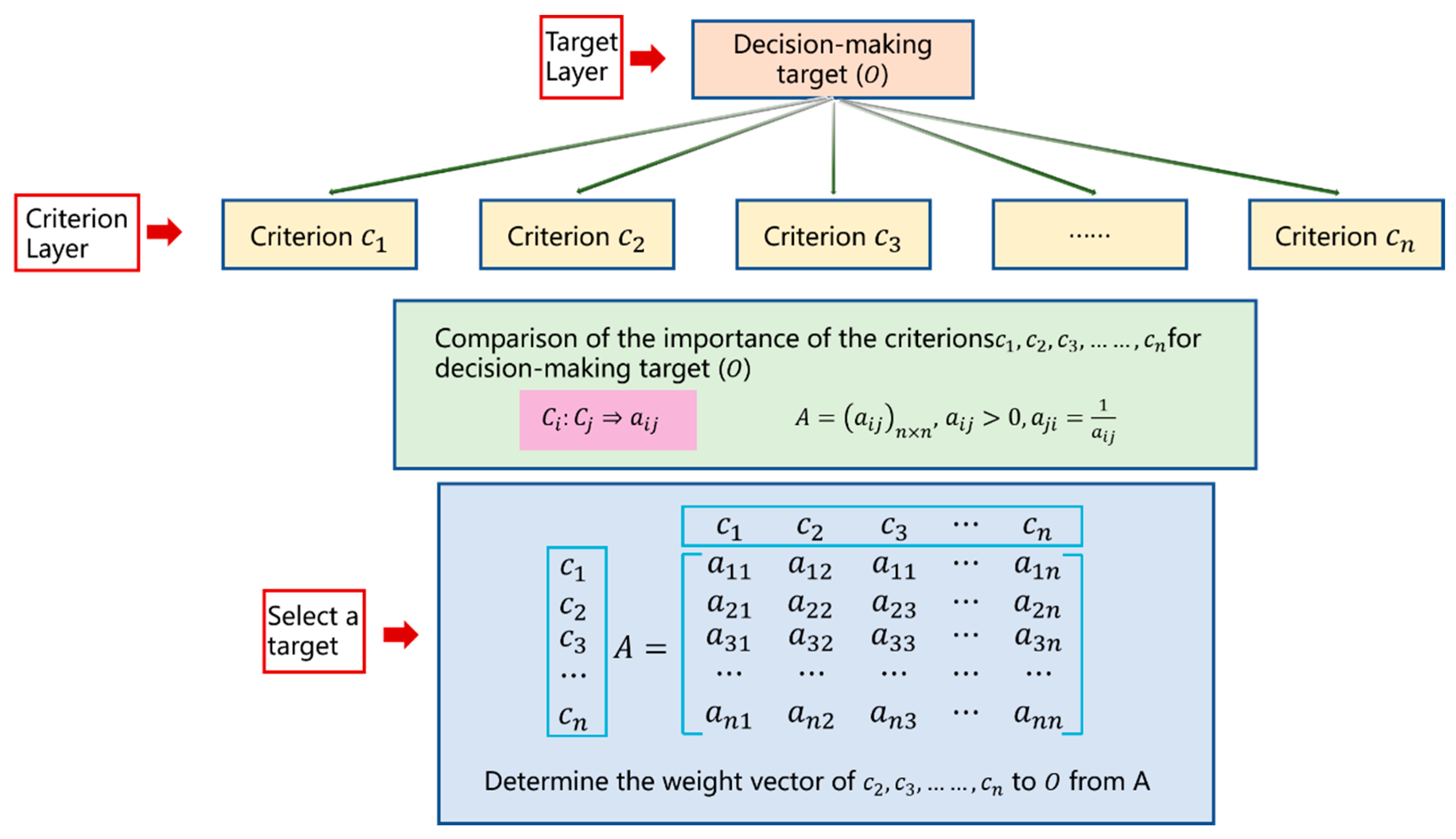
5.1. Theory of Analytical Hierarchy Process (AHP) Model Construction

The Analytic Hierarchy Process (AHP) is a systematic and hierarchical analysis method that combines qualitative and quantitative approaches. It was proposed by Thomas L. Saaty, a professor of operations research at the University of Pittsburgh, in the early 1970s, utilizing network system theory and multi-objective comprehensive evaluation methods [48,80,81,82]. In recent years, this method has been widely applied in the stability risk analysis and evaluation within the field of geotechnical engineering due to its clear logic, simplicity, and strong systematic nature [83]. In this study, the expert panel involved in the comparative analysis using the Analytic Hierarchy Process primarily consists of experts and scholars from universities and enterprises specializing in salt cavern research. For example, the panel includes experts from the Institute of Rock and Soil Mechanics, Chinese Academy of Sciences, Sichuan University, China National Petroleum Corporation, China Petroleum & Chemical Corporation, and the China Salt Industry Corporation.
When using the Analytic Hierarchy Process (AHP) for weight analysis, the following four steps are generally followed:
Structuring the Decision Elements
First, the decision goal is broken down into elements and these elements are grouped according to their nature into different levels, forming a hierarchy. The decision goal, criteria (decision criteria), and decision alternatives are organized into the highest, intermediate, and lowest levels, respectively, according to their relationships. A hierarchical structure diagram is then drawn.
Constructing the Judgment (Pairwise Comparison) Matrix
To determine the weights of various factors at each level, a consistent matrix method is used to quantify the weights. For a given criterion, pairwise comparisons are made between the alternatives, and their importance is rated. The element a i j represents the result of the comparison of the importance between element i and element j , and the matrix formed by these pairwise comparisons is called the judgment matrix. Table 2 shows the nine levels of importance and their assigned values. The construction of the judgment matrix is illustrated in Figure 5 [84,85].
Hierarchical Single Sorting and Consistency Test
For the eigenvector corresponding to the maximum eigenvalue λ m a x of the judgment matrix, after normalization, it is denoted as W , also known as the weight vector. The elements of W represent the ranking weights of the elements at the same level concerning an element at the preceding level. This process is called hierarchical single sorting. For the weight vector W :
A W = λ m a x W
where A is the judgment matrix, and W is the normalized eigenvector corresponding to the maximum eigenvalue λ m a x , the weight vector.
To confirm the hierarchical single sorting, a consistency test is required. The consistency index C I is used to measure consistency; the smaller the C I , the greater the consistency. The degree of inconsistency of A can be measured using the value of λ m a x n .
The consistency index is defined as:
C I = λ m a x n n 1
where C I = 0 indicates perfect consistency; C I close to 0 indicates satisfactory consistency; and the larger the C I , the more serious the inconsistency.
The random consistency index R I is introduced to measure the size of the C I . The R I is related to the order of the judgment matrix. Generally, the larger the order of the matrix, the greater the possibility of random consistency deviations. The corresponding relationship is shown in Table 3.
Considering that deviations in consistency may be due to random reasons, when testing whether the judgment matrix has satisfactory consistency, it is necessary to compare C I with R I to obtain the consistency ratio CR. The formula is as follows:
C R = C I R I
When the consistency ratio C R < 0.10 , the judgment matrix is considered to have passed the consistency test, and its normalized eigenvector can be used as the weight vector. Otherwise, it does not have satisfactory consistency, and the values of the elements in the judgment matrix A need to be adjusted.
Overall Hierarchical Ranking and Its Consistency Check
To obtain the combined weights of elements at a certain level in the hierarchical structure concerning the overall goal and their interactions with elements at the higher level, we need to use the results of the single rankings of all levels at that level to calculate the combined weights of elements at that level. This process is called overall hierarchical ranking. This step involves ranking from roof to floor layer by layer, and the final result gives the relative weights of the lowest level elements, which are the priorities of the decision-making alternatives [86].
If the previous level A contains m factors A 1 , A 2 , , A m with overall hierarchical ranking weights a 1 , a 2 , ,   a m , and the next level B contains n factors B 1 , B 2 , , B n , with single ranking weights for factor A j being b 1 j , b 2 j , b n j , then the overall hierarchical ranking weights for level B are as shown in Table 4 [87,88].
Clearly, j = 1 m i = 1 m a j b i j = 1 , meaning the overall hierarchical ranking remains a normalized vector.
The consistency check for the overall hierarchical ranking is also performed layer by layer from roof to floor. If the consistency index for certain factors in level B for the single ranking of A is C I j , and the corresponding average random consistency ratio is C R j , then the overall hierarchical ranking random consistency ratio is:
C R = a 1 C I 1 + a 2 C I 2 + + a m C I m a 1 R I 1 + a 2 R I 2 + + a m R I m = j = 1 m a j C I j j = 1 m a j R I j
When C R < 0.10 , the overall hierarchical ranking is considered to have passed the consistency check, indicating satisfactory consistency. Otherwise, the elements in the judgment matrices with high consistency ratios need to be readjusted.

5.2. Macro Suitability Assessment Method for Oil Storage

5.2.1. Establishment of the Evaluation System

Based on the Analytic Hierarchy Process (AHP) evaluation system, and following the basic principles of site selection and construction for salt cavern storage, various influencing factors for site selection are considered. The complex geological conditions of the site are broken down into several different levels, and then analyzed layer by layer with pairwise comparisons. This process creates a tree structure, quantifying subjective judgments to obtain the weights of the conditions for assessing the suitability of oil storage site selection.
Thus, the suitability assessment for the site selection and construction of salt cavern storage is set as the core objective layer. The macro-regional geological characteristics, basic geological characteristics of the mining area, basic characteristics of the salt layer for cavern construction, roof and floor characteristics of the salt layer, and surface factors are set as the criterion layer. The 14 basic indicators derived from further detailed analysis are placed in the evaluation layer, thereby establishing a hierarchical structure model for the suitability assessment of salt cavern storage site selection and construction. See Figure 6.

5.2.2. Weight Calculation

According to the hierarchical structure model for the suitability assessment of salt cavern storage construction, each factor in the criterion layer is compared pairwise. The comparison results are shown in Table 5.
Based on the above table, the judgment matrix A is
A = 1 2 3 3 5 1 / 2 1 2 2 4 1 / 3 1 / 2 1 1 3 1 / 3 1 / 2 1 1 3 1 / 5 1 / 4 1 / 3 1 / 3 1
Using MATLAB, the maximum eigenvalue λ m a x of A is calculated to be 5.4399. Substituting this value into Equation (2), we obtain:
C I =   λ m a x n n 1 = 0.109975  
Substituting C I = 0.109975 , C I = 1.12 into Equation (3), we get:
C R = C I R I = 0.0982 < 0.1
Thus, the consistency test is passed.
The normalized eigenvector corresponding to the maximum eigenvalue λ m a x is the weight vector:
W = 0.3918   0.2439   0.1425   0.1425   0.0793
Considering the weights of the evaluation layers further, the judgment matrices under each criterion are derived as follows:
C 1 = 1 1 1 1 1 1 1 1 1 ,   The   corresponding   weight   vector   W C 1 = [ 0.3333   0.3333   0.3333 ]
C 2 = 1 1 2 1 1 2 1 / 2 1 / 2 1 , The   corresponding   weight   vector   W C 2 = 0.4   0.4   0.2
C 3 = 1 2 3 1 / 2 1 2 1 / 3 1 / 2 1 , The   corresponding   weight   vector   W C 3 = 0.5396   0.2969   0.1635
C 4 = 1 1 1 1 1 1 1 1 1 , The   corresponding   weight   vector   W C 4 = 0.3333   0.3333   0.3333
C 5 = 1 3 1 / 3 1 , The   corresponding   weight   vector   W C 5 = 0.75   0.25
All of these matrices pass the consistency test.
The final weights of the factors are summarized in Table 6.

5.2.3. Suitability Assessment

Currently, China lacks engineering experience in constructing salt cavern storage facilities. The experiences from Europe and the United States are not entirely applicable to the site selection and construction of lake-type sedimentary salt cavern storage facilities in China. At present, it is not possible to establish a detailed reference index database to assess the feasibility of the salt cavern storage at the Jintan salt mine [89]. Given the similarities between the site selection and cavern construction stages of salt cavern storage and gas storage, and the successful operational experience of salt cavern gas storage facilities in China, it is necessary to moderately reference the site selection and construction experience of gas storage facilities for establishing suitability grading standards for salt cavern storage construction. By combining the suggestions of experts and engineers in the field with relevant theoretical research findings [41,90,91,92], preliminary suitability grading standards for the site selection and construction indicators of layered salt cavern storage facilities have been proposed, as shown in Table 7. These standards aim to facilitate the quantitative analysis of relevant indicators for the suitability assessment of specific salt mine storage sites.
Based on the suitability grading of various indicators for the site selection and construction of stratified salt cavern storage, as detailed in Table 7, we derive the evaluation values P i   ( i = 1 , 2 , , 14 ) for each indicator of the target salt mine. Using the weights W i *   ( i = 1 , 2 , , 14 ) obtained through the Analytic Hierarchy Process for each indicator in the overall evaluation system for salt cavern storage site selection and construction, as shown in Table 6, the suitability P of the target mining area for salt cavern storage site selection and construction is calculated as follows (Equation (9)):
P = j = 1 14 P i W i *
By substituting the calculated suitability P from Equation (9) into the comprehensive suitability degree evaluation table (Table 8), the suitability grade for the salt cavern storage in the mining area can be determined.

5.3. Engineering Application

In this section, the Jintan Salt Mine in Jiangsu Province is examined as a representative candidate site for the national strategic petroleum reserves. The Jintan Salt Mine is located in the northwest of Jintan City, Jiangsu Province, approximately 100 km from Nanjing and 45 km from Changzhou. The geographical coordinates are between 119°21′ and 119°27′ east longitude and between 31°46′ and 31°51′ north latitude. The Jintan depression is a Cenozoic rift basin, trending northeast, with a length of 33 km in the northeast direction and a width of about 22 km in the northwest direction, covering a total area of approximately 526 km2. It is a secondary structural unit within the Changzhou depression zone of the southern Jiangsu uplift area. The eastern and southern parts are adjacent to the Shanghuang–Dahua uplift, the north is separated by the Lingkou Basin from the Ningzhen uplift, and the west borders the Maoshan thrust belt [93]. By 2014, the first phase of the national strategic oil reserves project had achieved an oil reserve of 12.43 million tons. The construction of the second phase has been completed, and the third phase is currently in the planning stage, with a focus on deep underground oil storage facilities.
A detailed investigation of the macro-engineering geological characteristics of this area was conducted, providing an in-depth understanding of the formation characteristics of the Jintan Salt Mine, regional sealing performance, regional fault structures, regional hydrological characteristics, vertical and horizontal physical property distribution characteristics of the salt mine, and regional trapping performance. Using the macro suitability evaluation system for the site selection and construction of salt cavern storage proposed earlier, the macro suitability of the Jintan Salt Mine area for constructing a storage facility was assessed. Overall, based on the data from Table 7, the suitability grades of various indicators for the Jintan Salt Mine were classified, as detailed in Table 9.
Based on the analysis, the suitability grades for various indicators of the Jintan Salt Mine, as detailed in Table 7, can be classified as shown in Table 9. The scores for the 14 basic evaluation indicators P 1 ~ P 14 are as follows: 10, 8, 10, 8, 8, 10, 8, 10, 8, 8, 6, 8, 10, 6. Substituting the scores and weights of each basic evaluation indicator into Equation (10):
P = i = 1 14 P i W i *  
we obtain the suitability PPP of the Jintan Salt Mine for salt cavern storage site selection and construction as P = 8.6898. Referring to the comprehensive suitability degree evaluation table for storage site construction (Table 8), the Jintan Salt Mine falls into the category of “Suitable Site” for the construction of a salt cavern storage facility (7 < P ≤ 9). This indicates that the region possesses the engineering geological conditions suitable for the construction of an underground strategic petroleum reserve storage facility and can be considered a preferred site for the national underground strategic petroleum reserves. This evaluation result is consistent with expert opinions.

6. Conclusions

This paper analyzed the current status of salt cavern storage for oil domestically and internationally. Currently, this method is an important approach for strategic oil storage in many countries around the world, particularly in North America and Europe. At present, China has no engineering cases of salt cavern storage for oil. China has the basic conditions to implement large-scale salt cavern strategic petroleum reserves. The country has abundant well salt resources, a dense and complete oil transportation pipeline network, and technical support and construction experience from the underground gas storage facility associated with West-to-East Gas.
China has the capability to build salt cavern storage facilities, but the development is still in its early stages. Current challenges include the need for methods and standards to evaluate the large number of existing dissolution caverns; the need for improvement in the engineering technology for constructing storage facilities; and issues with injection and extraction operations, such as cavern stability and crystallization blockages in the injection and extraction columns.
Based on the Analytic Hierarchy Process (AHP), a macro suitability hierarchical structure evaluation system for the site selection and construction of salt cavern storage facilities has been constructed. Suitability grading standards for the site selection and construction indicators of storage facilities have been provided, and a suitability assessment method applicable to the site selection and construction of storage facilities in different salt rock structural regions has been proposed. Applying this method to the site selection evaluation of the Jintan Salt Mine salt cavern storage facility, the results indicate that the Jintan Salt Mine has high suitability for storage site selection, making it an ideal site for construction. This provides a reference for the macro evaluation of the feasibility of constructing underground salt cavern storage facilities for oil in China.

Author Contributions

Investigation, S.J. and X.S.; Resources, B.Y. and Y.Z.; Writing—original draft, X.G.; Writing—review and editing, N.Z. All authors have read and agreed to the published version of the manuscript.

Funding

The authors wish to acknowledge the financial support from the National Natural Science Foundation of China Youth Science Foundation Project (52204152,52204111,52204153), the Postdoctoral Innovation Talent Support Program (BX2020275), and the Postdoctoral Science Foundation (2020M683521).

Data Availability Statement

Data are contained within the article.

Acknowledgments

A special acknowledgement should be shown to the anonymous reviewers for their constructive and valuable comments. We thank them for taking time from their busy schedule to provide guidance.

Conflicts of Interest

The authors declare no conflicts of interest.

References

  1. Zheng, X.; Shi, J.; Cao, G.; Yang, N.; Cui, M.; Jia, D.; Liu, H. Progress and prospects of oil and gas production engineering tech-nology in China. Pet. Explor. Dev. 2022, 49, 644–659. [Google Scholar] [CrossRef]
  2. Qiao, L.; Li, C.; Wang, Z.; Wang, X.; Guo, J. Seawater intrusion into an underground water-sealed oil storage cavern: Effects of water curtain system, hydraulic conductivity and dispersivity. Tunn. Undergr. Space Technol. Inc. Trenchless Technol. Res. 2022, 126, 104542. [Google Scholar] [CrossRef]
  3. Paik, I.; Leiby, P.; Jones, D.; Yokobori, K.; Bowman, D. Strategic oil stocks in the APEC region. In Proceedings of the 22nd IAEE Annual International Conference, Rome, Italy, 9–12 June 1999; International Association for Energy Economists: Rome, Italy, 1999. [Google Scholar]
  4. Molecke, M.A. Final State of the Strategic Petroleum Reserve (SPR) Weeks Island Mine; Sandia National Laboratories: Albuquerque, NM, USA, 2000; pp. 1–63.
  5. Grappe, J. UGS technology improvements: Some answers of the UGS industry to the evolution of gas markets. In Proceedings of the International Gas Union Research Conference, Paris, France, 8–10 October 2008; pp. 461–472. [Google Scholar]
  6. Silva, L.; Soares, C.G. Robust optimization model of an offshore oil production system for cost and pipeline risk of failure. Reliab. Eng. Syst. Saf. 2023, 232, 109052. [Google Scholar] [CrossRef]
  7. Zhu, Y. Research on Facilities of Strategic Petroleum Reserve; China University of Petroleum: Beijing, China, 2008. [Google Scholar]
  8. Zhao, K.; Liu, Y.; Li, Y.; Ma, H.; Hou, W.; Yu, C.; Liu, H.; Feng, C.; Yang, C. Feasibility analysis of salt cavern gas storage in extremely deep formation: A case study in China. J. Energy Storage 2022, 47, 103649. [Google Scholar] [CrossRef]
  9. Skrzypkowski, K.; Korzeniowski, W.; Poborska-Młynarska, K. Binding Capability of Ashes and Dusts from Municipal Solid Waste Incineration with Salt Brine and Geotechnical Parameters of the Cemented Samples. Arch. Min. Sci. 2018, 63, 903–918. [Google Scholar]
  10. Waldemar, K.; Katarzyna, P.M.; Krzysztof, S. The Idea of the Recovery of Municipal Solid Waste Incineration (MSWI) Residues in Kodawa Salt Mine S.A. by Filling the Excavations with Self-Solidifying Mixtures. Arch. Min. Sci. 2018, 63, 553–565. [Google Scholar]
  11. Hunsche, U. Uniaxial and triaxial creep and failure tests on rock: Experimental technique and interpretation. In Visco-Plastic Behaviour of Geomaterials; Springer: Vienna, Austria, 1994. [Google Scholar]
  12. Burgherr, P.; Eckle, P.; Hirschberg, S. Comparative assessment of severe accident risks in the coal, oil and natural gas chains. Reliab. Eng. Syst. Saf. 2012, 105, 97–103. [Google Scholar] [CrossRef]
  13. Tsvetkova, A. World experience of strategic reserves mineral. In Proceedings of the 3rd International Conference on Management–Economics–Ethics–Technology (MEET 2017), Gliwice, Poland, 21–22 September 2017. [Google Scholar]
  14. Zhang, D. A Study on China Strategic Petroleum Reserve; Wuhan University: Wuhan, China, 2014. [Google Scholar]
  15. Yuan, G.; Xia, Y.; Jin, G. Present state of underground storage and development trends in engineering technologies at home and abroad. Pet. Drill. Technol. 2017, 45, 8–14. [Google Scholar]
  16. Tillerson, J.R. Geomechanics Invetigations of SPR Crude Oil Storage Caverns; SAND-79-2031C; Sandia National Laboratories: Albuquerque, NM, USA, 1979.
  17. Leiby, P.N.; Bowman, D. The Value of Expanding the U.S. Strategic Petroleum Reserve; ORNL/TM-2000/179; Oak Ridge National Laboratory: Oak Ridge, TN, USA, 2000.
  18. Lord, D.L.; Checkai, D.; Eldredge, L.; Osborne, G. Pressure trending analysis to support cavern integrity monitoring at the U.S. Strategic petroleum reserve. In Proceedings of the Solution Mining Research Institute Technical Conference, San Antonio, TX, USA, 5–6 May 2014. [Google Scholar]
  19. Langer, M. Use of solution-mined caverns in salt for oil and gas storage and toxic waste disposal in Germany. Eng. Geol. 1993, 35, 183–190. [Google Scholar] [CrossRef]
  20. Davis, R.M. National strategic petroleum reserve. Science 1981, 213, 618–622. [Google Scholar] [CrossRef]
  21. Nilsen, B. Norwegian oil and gas storage in rock caverns—Technology based on experience from hydropower development. J. Rock Mech. Geotech. Eng. 2021, 13, 479–486. [Google Scholar] [CrossRef]
  22. Lin, L. Drawing on foreign experience to create a strategic petroleum reserve model with Chinese characteristics. Shandong Ind. Technol. 2013, 32, 18–19. [Google Scholar] [CrossRef]
  23. Huang, Y.; Chen, L. Optimal selection of underground salt cavern oil storage site. Oil Gas Storage Transp. 2011, 30, 117–120. [Google Scholar]
  24. Li, J. China Has Built 9 Major Oil Reserve Bases. People’s Daily 2017, 70, 3–5. [Google Scholar]
  25. Yang, C.; Wang, T. Advance in deep underground energy storage. Chin. J. Rock Mechan-Ics Eng. 2022, 41, 1729–1759. [Google Scholar]
  26. Cyran, K. Insight into a Shape of Salt Storage Caverns. Arch. Min. Sci. 2020, 65, 363–398. [Google Scholar]
  27. Wang, Z.; Li, Y.; Zhang, L. Engineering geological conditions and feasibility analysis of under-ground gas storage in thin-layered salt rock. J. Eng. Geol. 2015, 23, 148–154. [Google Scholar]
  28. Liu, W.; Du, J.; Li, Q.; Shi, X.; Chen, J.; Yi, W.; He, T.; Li, D.; Dong, Y.; Jiang, D.; et al. Feasibility analysis on the utilization of TWH-caverns with sediment space for gas storage: A case study of Sanshui salt mine. J. Energy Storage 2023, 75, 109576. [Google Scholar] [CrossRef]
  29. Ding, G.; Xie, P. Salt cavern available for state strategic petroleum storage. Oil Gas Storage Transp. 2006, 25, 16–19. [Google Scholar]
  30. Liu, W.; Dong, Y.K.; Zhang, Z.X.; Li, L.; Jiang, D.Y.; Fan, J.Y.; Chen, J.; Zhang, X.; Wan, J.F.; Li, Z.Z. Optimization of operating pressure of hydrogen storage salt cavern in bedded salt rock with multi-interlayers. Int. J. Hydrogen Energy 2024, 58, 974–986. [Google Scholar] [CrossRef]
  31. Li, J.; Wan, J.; Liu, H.; Jurado, M.J.; He, Y.; Yuan, G.; Xia, Y. Stability Analysis of a Typical Salt Cavern Gas Storage in the Jintan Area of China. Energies 2022, 15, 4167. [Google Scholar] [CrossRef]
  32. Shi, X.L.; Yang, C.H.; Li, Y.P.; Li, J.L.; Ma, H.L.; Wang, T.T.; Guo, Y.T.; Chen, T.; Chen, J.; Liu, W.; et al. Development prospect of salt cavern gas storage and new research progress of salt cavern leaching in China. In Proceedings of the 51st U.S. Rock Mechanics/Geomechanics Symposium, San Francisco, CA, USA, 25–28 June 2017. [Google Scholar]
  33. Wu, W.; Xu, S.; Yang, C.; Bai, S. Testing studies on response behaviour of rock salt to impacting. Chin. J. Rock Mech. Eng. 2004, 23, 3613. [Google Scholar]
  34. Zhang, N.; Liu, X.; Zhang, Y.; Gu, H.; Yan, B.; Jia, Q.; Gao, X. Investigating the Mechanism of Land Subsidence Due to Water Network Integration at the Guangzhou Longgui Salt Mine and Its Impact on Adjacent Subway. Water 2024, 16, 1723. [Google Scholar] [CrossRef]
  35. Jiang, D.Y.; Ren, T.; Chen, J.; Ren, S.; Fan, X.Q.; Yang, C.H. Experimental study on mechanical characteristics of molded salt rock with weak interlayer. Chin. J. Rock Mech. Eng. 2012, 31, 1797–1803. [Google Scholar]
  36. Chen, W.; Tan, X.; Wu, G. Gas leakage assessment method of underground gas storage in multi-interlayer salt mine. Chin. J. Rock Mech. Eng. 2008, 28, 11–20. [Google Scholar] [CrossRef]
  37. Chen, X.; Li, Y.; Yin, H. Evaluation method for gas leakage in multi-layered salt rock underground storage. Rock Soil Mech. 2018, 40, 11–20. [Google Scholar] [CrossRef]
  38. Wang, J.; Wang, X.; He, M.; Song, Z.; Feng, S.; Liu, X.; Zhang, Y. Long-term stability analysis and evaluation of horizontal salt cavern gas storage. J. Energy Storage 2023, 66, 107413. [Google Scholar] [CrossRef]
  39. Xuan, Z. Research on China’s salt mine resources and salt chemical industry areas. Lake Salt Res. 1996, Z1, 69–72. [Google Scholar]
  40. Li, W.; Ding, G.; Zhang, Y. Feasibility of underground oil reserve in China. Petrochem. Technol. Econ. 2002, 19, 14–18. [Google Scholar]
  41. Li, J. Using salt beds to build underground gas storages with salt caves. Nat. Gas Ind. 2004, 24, 119–121. [Google Scholar]
  42. Yang, C.H.; Liang, W.G.; Wei, D.H.; Yang, H.J. Investigation on possibility of energy storage in salt rock in China. Chin. J. Rock Mech. Eng. 2005, 24, 4409. [Google Scholar]
  43. Park, B.Y.; Ehgartner, B.L. Sensitivity of Storage Field Performance to Geologic and Cavern Design Parameters in Salt Domes. In Proceedings of the 44th U.S. Rock Mechanics Symposium and 5th U.S.—Canada Rock Mechanics Symposium, Salt Lake City, UT, USA, 27–30 June 2010. [Google Scholar]
  44. Park, B.Y.; Ehgartner, B.L.; Herrick, C.G. Allowable Pillar to Diameter Ratio for Strategic Petroleum Reserve Caverns. In Proceedings of the 45th U.S. Rock Mechanics/Geomechanics Symposium, San Francisco, CA, USA, 26–29 June 2011. [Google Scholar]
  45. Wei, X.; Shi, X.; Li, Y.; Li, P.; Ban, S.; Zhao, K.; Ma, H.; Liu, H.; Yang, C. A comprehensive feasibility evaluation of salt cavern oil energy storage system in China. Appl. Energy 2023, 351, 121807. [Google Scholar] [CrossRef]
  46. Yang, C.; Jing, W.; Daemen, J.J.; Zhang, G.; Du, C. Analysis of major risks associated with hydrocarbon storage caverns in bedded salt rock. Reliab. Eng. Syst. Saf. 2013, 113, 94–111. [Google Scholar] [CrossRef]
  47. Yin, X.; Zhang, Z. Cementing technology for Jintan salt cavern underground gas storage. Pet. Drill. Technol. 2006, 34, 3. [Google Scholar]
  48. Liu, X.; Zhao, N.; Yang, X.; Hen, Z. Application of high water absorption temporary plugging completion fluid in Hutubi gas storage well completion. Pet. Drill. Technol. 2013, 41, 6. [Google Scholar]
  49. Cyran, K.; Kowalski, M. Shape Modelling and Volume Optimisation of Salt Caverns for Energy Storage. Appl. Sci. 2021, 11, 423. [Google Scholar] [CrossRef]
  50. Bruno, M.; Dorfmann, L.; Han, G.; Lao, K.; Young, J. 3D geomechanical analysis of multiple caverns in bedded salt. In Proceedings of the SMRI Fall 2005 Meeting, Nancy, France, 1–5 October 2005. [Google Scholar]
  51. Ding, G. Demand and challenges of underground gas storage in China. Nat. Gas Ind. 2011, 31, 90–93+131. [Google Scholar]
  52. Wan, J.; Meng, T.; Li, J.; Liu, W. Energy storage salt cavern construction and evaluation technology. Adv. Geo-Energy Res. 2023, 9, 141–145. [Google Scholar] [CrossRef]
  53. Gou, Y.; Bai, S.; Jia, J.; Li, K.; Li, F.; Ran, L. Feasibility analysis of single well and double cavity in the salt-cavern gas storage with thick sandwiches. Oil Drill. Prod. Technol. 2020, 42, 449–453. [Google Scholar]
  54. Jing, W.; Yang, C.; Li, Y.; Yang, C. Research on the feasibility of Jintan salt cavern as an underground gas storage site. Nat. Gas Ind. 2005, 25, 118–120. [Google Scholar]
  55. Lux, K.H. Gebirsmechanischer Entwurf und Felderfahrungen im Salzkavernenbau: Ein Beitrag zur Entwicklung von Prognosemodellen für den Hohlraumbau im duktilen Salzgebirge; Ferdinand Enke: Stuttgart, Germany, 1984. [Google Scholar]
  56. Fu, J.; Wang, X.; Ding, M.M.; Yang, G.B.; Zhang, S.Y.; Liu, B.S.; Chen, C. Research on Construction and Operation Parameters of an Underground Oil Storage in Depleted Salt Caverns in the East of China. Presented at the SPE Europec Featured at 82nd EAGE Conference and Exhibition, Amsterdam, The Netherlands, 18–21 October 2021. [Google Scholar] [CrossRef]
  57. Pan, J. China’s Energy Resources Issues and Construction of the State Petroleum Strategic Reserve. Oil Gas Storage Transp. 2004, 23, 1–3. [Google Scholar]
  58. Yang, Y. Feasibility Analysis on Using Underground Cavern as State Oil Strategic Reserves. OGST 2004, 23, 22–24. [Google Scholar]
  59. Song, H.; Zhu, S.; Li, J.; Wang, Z.; Li, Q.; Ning, Z. Design Criteria for the Construction of Energy Storage Salt Cavern Considering Economic Benefits and Resource Utilization. Sustainability 2023, 15, 6870. [Google Scholar] [CrossRef]
  60. Xia, X.; Liu, Y. A Brief Discussion on the Construction of Underground Oil Reservoirs in China. Pet. Plan. Des. 2004, 15, 26–27. [Google Scholar]
  61. Liu, Y.; Li, Y.; Ma, H.; Shi, X.; Zheng, Z.; Dong, Z.; Zhao, K. Detection and Evaluation Technologies for Using Existing Salt Caverns to Build Energy Storage. Energies 2022, 15, 9144. [Google Scholar] [CrossRef]
  62. Jing, G.; He, J.; Chen, J.; Zhou, D.; Wang, X.; Liu, J.; Qi, D. Potential Analysis of Huai’an Salt Cavern Oil Storage. Oil Gas Storage Transp. 2017, 36, 875–882. [Google Scholar]
  63. Tan, Y.; Song, C. Analysis of Key Technical Points for Using Salt Caverns for Strategic Petroleum Storage. Oil Gas Storage Transp. 2008, 27, 1–4. [Google Scholar]
  64. Chen, J.; Tan, Y.; Yu, Q. Key Points in the Planning and Design of Underground Gas Storage. Oil Gas Storage Transp. 2001, 20, 13–16. [Google Scholar]
  65. Wang, T.; Yang, C.; Ma, H.; Daemen, J.J.K.; Wu, H. Safety evaluation of gas storage caverns located close to a tectonic fault. J. Nat. Gas Sci. Eng. 2015, 23, 281–293. [Google Scholar] [CrossRef]
  66. Walder, J.; Nur, A. Permeability measurement by the pulse-decay method: Effects of poroelastic phenomena and non-linear pore pressure diffusion. Int. J. Rock Mech. Min. Sci. Geomech. Abstr. 1986, 23, 225–232. [Google Scholar] [CrossRef]
  67. Gu, H.; Lai, X.; Tao, M.; Momeni, A.; Zhang, Q. Dynamic mechanical mechanism and optimization approach of roadway surrounding coal water infusion for dynamic disaster prevention. Measurement 2023, 223, 113639. [Google Scholar] [CrossRef]
  68. Chen, X.; Li, Y.P.; Ge, X.B.; Shi, X.L.; Xue, T.F. Simulating brine transport in strata of a bedded salt cavern storage with a Fluid–Solid Coupling Model. Eng. Geol. 2020, 271, 105595. [Google Scholar] [CrossRef]
  69. Yang, C.; Chen, F.; Zeng, Y. Investigation on reep damage constitutive theory of salt rock. Chin. J. Rock Mech. Eng. 2002, 3, 1602–1604. [Google Scholar] [CrossRef]
  70. Gao, R.; Kuang, T.; Meng, X.; Huo, B. Effects of ground fracturing with horizontal fracture plane on rock breakage characteristics and mine pressure control. Rock Mech. Rock Eng. 2021, 54, 3229–3243. [Google Scholar] [CrossRef]
  71. Gao, R.; Bai, D.; Yu, B.; Tai, Y.; Meng, X.; Zhang, W. Ground fracturing of multi-strata for strong ground pressure control in extra-thick coal seams with hard roofs: Numerical simulation and case study. Eng. Fract. Mech. 2024, 303, 110129. [Google Scholar] [CrossRef]
  72. Zhu, D.; Yu, B.; Wang, D.; Zhang, Y. Fusion of finite element and machine learning methods to predict rock shear strength parameters. J. Geophys. Eng. 2024, 21, 1183–1193. [Google Scholar] [CrossRef]
  73. Zhang, S.; Zhang, D.; Feng, G.; Chi, M. Modelling method of heterogeneous rock mass and DEM investigation of seepage characteristics. Géoméch. Geophys. Geo-Energy Geo-Resour. 2024, 10, 1–22. [Google Scholar] [CrossRef]
  74. Wei, L.; Jie, C.; Deyi, J.; Xilin, S.; Yinping, L.; Daemen, J.J.K.; Chunhe, Y. Tightness and suitability evaluation of abandoned salt caverns served as hydrocarbon energies storage under adverse geological conditions (AGC). Appl. Energy 2016, 178, 703–720. [Google Scholar] [CrossRef]
  75. Ge, X.; Li, Y.; Shi, X.; Ma, H.; Wang, K.; Yin, H. Dynamics and enhanced stability properties of slender leaching tubings in salt cavern storage with a Y-type manifold fitted at free downstream end. J. Energy Storage 2021, 43, 103170. [Google Scholar] [CrossRef]
  76. Hoffman, E.L. Effects of Cavern Spacing on the Performance and Stability of Gas-Filled Storage Caverns; SAND-92-2545; Sandia National Laboratories: Albuquerque, NM, USA, 1993.
  77. Hoffman, E.L. Effects of Cavern Depth on Surface Subsidence and Storage Loss of Oil-Filled Caverns; SAND-92-0053; Sandia National Laboratories: Albuquerque, NM, USA, 1992.
  78. Hoffman, E.L.; Ehgartner, B.L. Using Three Dimensional Structural Simulations to Study the Interactions of Multiple Excavations in Salt; SAND-97-1017C; Sandia National Laboratories: Albuquerque, NM, USA, 1998.
  79. Yang, C.; Daemen, J.J.K.; Yin, J.H. Experimental investigation of creep behavior of salt rock. Int. J. Rock Mech. Min. Sci. 1999, 36, 233–242. [Google Scholar] [CrossRef]
  80. Huang, M.; Liu, W.; Shi, X. Engineering Geology Characteristics of Jintan Salt Mine. Soil Eng. Found. 2014, 28, 92–95. [Google Scholar]
  81. Ding, L. Research on estimation of slope stability based on improved grey correlation analysis and analytic hierarchy process. Rock Soil Mech. 2011, 32, 3437–3441. [Google Scholar]
  82. Haghiri, M.; Raeisi, N.; Azizi, R.; Shabani, K.; Ghadiri, M. Evaluation of karst aquifer development and karst water resource potential using fuzzy logic model (FAHP) and analysis hierarchy process (AHP): A case study, North of Iran. Carbonates Evaporites 2024, 39, 11. [Google Scholar] [CrossRef]
  83. Zhai, Y.; Cao, W.; Wang, J.; Zhang, Y. Slope Stability Fuzzy Evaluation Method Based on Uncertain Analytic Hierarchy Process. Rock Soil Mech. 2011, 32, 539–543. [Google Scholar] [CrossRef]
  84. Vaidya, O.S.; Kumar, S. Analytic hierarchy process: An overview of applications. Eur. J. Oper. Res. 2006, 169, 1–29. [Google Scholar] [CrossRef]
  85. Saaty, T.L. Decision making with the analytic hierarchy process. Int. J. Serv. Sci. 2008, 1, 83–98. [Google Scholar] [CrossRef]
  86. Abrahamsen, E.B.; Milazzo, M.F.; Selvik, J.T.; Asche, F.; Abrahamsen, H.B. Prioritising investments in safety measures in the chemical industry by using the Analytic Hierarchy Process. Reliab. Eng. Syst. Saf. 2020, 198, 106811. [Google Scholar] [CrossRef]
  87. Zhang, H.; Liu, C.; Hu, B. Analysis of Factors Influencing Brand Competitiveness of Beijing Vegetable Cooperatives Based on Analytic Hierarchy Process. North. Hortic. 2020, 44, 155–164. [Google Scholar]
  88. Zhao, X. Performance Evaluation of Dealers Based on Analytic Hierarchy Model. Mark. Mod. 2009, 38, 21–23. [Google Scholar]
  89. Wei, X.; Shi, X.; Li, Y. Optimization of engineering for the salt cavern oil storage (SCOS) during construction in China. Geoenergy Sci. Eng. 2024, 233, 212567. [Google Scholar] [CrossRef]
  90. Wu, W.; Hou, Z.; Yang, C. Investigation on Evaluating Criteria of Stabilities for Energy (Petroleum and Natural Gas) Storage Caverns in Rock Salt. Chin. J. Rock Mech. Eng. 2005, 24, 9. [Google Scholar]
  91. Yin, X.; Yang, C.; Li, Y. Influence of mudstone interlayer on stability of oil storage in laminated salt rock. Rock Soil Mech. 2006, 27, 344–348. [Google Scholar]
  92. Yin, X.; Yang, C.; Chen, J. Numerical simulation research on long-term stability of gas storage in Jintan salt mine. Rock Soil Mech. 2006, 27, 869–874. [Google Scholar]
  93. Zhao, X. Project Risk Management. Soc. Sci. 2005, S1, 391–392. [Google Scholar]
Figure 1. Outer dependency for oil of China and days of oil availability by country [1].
Processes 12 01709 g001
Figure 2. Distribution of U.S. strategic oil storage.
Processes 12 01709 g002
Figure 3. Distribution of China’s strategic oil storage.
Processes 12 01709 g003
Figure 4. The process of solution mining during the construction of SPR in rock salt.
Processes 12 01709 g004
Figure 5. Construction of the judgment matrix in AHP. O represents the decision objective. Ci represents the evaluation criterion.
Processes 12 01709 g005
Figure 6. Target hierarchy model of the suitability evaluation of the SPR salt cavern. O represents the decision objective; Ci represents the evaluation criterion; Cij represents the jth basic indicator under the ith evaluation criterion in the criterion layer.
Processes 12 01709 g006
Table 1. Salt cavern oil storage in China.
Oil Storage BasesTotal Storage Capacity ( m 3 )Remarks
Zhoushan 500 × 10 4 Surface storage bases
Zhoushan Expansion 250 × 10 4 Surface storage bases
Zhenhai 520 × 10 4 Surface storage bases
Dalian 300 × 10 4 Surface storage bases
Huangdao 320 × 10 4 Surface storage bases
Dushanzi 300 × 10 4 Surface storage bases
Lanzhou 300 × 10 4 Surface storage bases
Tianjin 320 × 10 4 Surface storage bases
Huangdao national oil reserve cavern 300 × 10 4 Underground storage bases
Table 2. Scale method of the judgment matrix of element aij.
Scale a i j Meaning of Importance Comparison
1 i and j are equally important
3 i is slightly more important than j
5 i is moderately more important than j
7 i is strongly more important than j
9 i is extremely more important than j
2, 4, 6, 8Intermediate values between the adjacent judgments
1, 1/2, …, 1/9 i compared to j in the reverse order of the above comparisons
Table 3. The standard value of random consistency index RI.
n12345678910
RI000.580.901.121.241.321.411.451.49
Table 4. Weight calculation of total hierarchical ordering.
Level AA1A2……AmTotal Ranking of Level B
Level B a1a2……am
B1b11b12……b1m j = 1 m a j b 1 j
B2b21b22……b2m j = 1 m a j b 2 j
………………………………
Bnbn1bn2……bnm j = 1 m a j b n j
Table 5. Index comparison and the table of aij.
Indicator
C i : C j
Relation to
a i j
Indicator
C i : C j
Relation to
a i j
Indicator
C i : C j
Relation to
a i j
Indicator
C i : C j
Relation to
a i j
Indicator
C i : C j
Relation to
a i j
C 1 : C 1 Same
1
C 1 : C 2 Same-slightly more
2
C 1 : C 3 Slightly more
3
C 1 : C 4 Slightly more
3
C 1 : C 5 More
5
C 2 : C 1 Same-slightly less
1/2
C 2 : C 2 Same
1
C 2 : C 3 Same-slightly more
2
C 2 : C 4 Same-slightly more
2
C 2 : C 5 Slightly more-more
4
C 3 : C 1 Slightly less
1/3
C 3 : C 2 Same-slightly less
1/2
C 3 : C 3 Same
1
C 3 : C 4 Same
1
C 3 : C 5 Slightly more
3
C 4 : C 1 Slightly less
1/3
C 4 : C 2 Same-slightly less
1/2
C 4 : C 3 Same
1
C 4 : C 4 Same
1
C 4 : C 5 Slightly more
3
C 5 : C 1 Less
1/5
C 5 : C 2 Slightly less-less
1/4
C 5 : C 3 Slightly less
1/3
C 5 : C 4 Slightly less
1/3
C 5 : C 5 Same
1
Table 6. Summary table of corresponding weighting value of each factor.
Goal LayerCriterion LayerCriterion Layer WeightEvaluation LayerEvaluation Layer WeightWeight Relative to Goal Layer w * (Criterion Layer Weight Evaluation Layer Weight)
The suitability assessment for the site selection and construction of salt cavern storageMacro-regional geological characteristics0.3918Regional tectonic characteristics
Regional sedimentary characteristics
Regional hydrological characteristics
0.3333
0.3333
0.3333
0.1306
0.1306
0.1306
Basic Geological Characteristics of the Mining Area0.2439Characteristics of rock layer distribution
Interbedded distribution characteristics
Average grade of ore body
0.4000
0.4000
0.2000
0.0976
0.0976
0.0488
Basic characteristics of the salt layer for cavern construction0.1425Insoluble matter content of salt layer and interlayer
Depth of the salt roof
Interbedded salt layer thickness ratio
0.5396
0.2969
0.1635
0.0769
0.0423
0.0233
Roof and floor characteristics of the salt layer0.1425Mechanical properties of roof and floor
Pore and seepage characteristics of roof and floor Characteristics of fracture development of roof and floor
0.3333
0.3333
0.3333
0.0475
0.0475
0.0475
surface factors0.0793Distance to the pier and oil pipelines
Population and building density
0.7500
0.2500
0.0595
0.0198
Table 7. Index suitability grade of the SPR cavern during site selection and construction.
SuitabilityBestSuitableAveragePoor
Evaluation
Index
10864
Macro-regional geological characteristicsRegional tectonic characteristicsSeismic activity is very weak, no active faults within 1 km of the storage areaSeismic activity is weak, no active faults within 300–1000 m of the storage areaNo major historical earthquakes recently, no active faults within 300–1000 m of the storage areaRecent major historical earthquakes, or recent major historical earthquakes present
Regional sedimentary characteristicsMarine sedimentation, thick salt dome, thickness ≥ 400 mMarine sedimentation, thick salt dome, thickness 150~400 mMarine sedimentation, thick salt dome, thickness 100~150 mMarine sedimentation, thick salt dome, thickness < 100 m
Regional hydrological characteristicsAmple surface fresh water close to the site, salt mine layer isolated from groundwater systemAmple surface fresh water close to the site, salt mine layer isolated from groundwater systemAmple surface fresh water at a distance, salt mine layer isolated from groundwater systemLack of surface fresh water, or salt mine layer connected to groundwater system
Basic Geological Characteristics of the Mining AreaCharacteristics of rock layer distributionSalt mine distribution area ≥ 100 km2Salt mine distribution area 50~100 km2Salt mine distribution area 20~50 km2Salt mine distribution area < 20 km2
Interbedded distribution characteristicsSmall thickness and very few interlayers within and between layersMore interlayers but small thicknessNumerous thin interlayers, occasionally thick interlayers > 10 mNumerous thick interlayers
Average grade of ore body≥85%70~85%50~70%<50%
Basic characteristics of the salt layer for cavern constructionInsoluble matter content of salt layer and interlayerInsoluble content < 5%, overall solubility > 90%Insoluble content 5~10%, overall solubility 75~90%Insoluble content 10~15%, overall solubility 60~75%Insoluble content > 15%, overall solubility < 60%
Depth of the salt roof800~1500 m1500~2500 m600~800 m or >2500 m<600 m
Interbedded salt layer thickness ratio<5%5~20%20~40%>40%
Roof and floor characteristics of the salt layerMechanical properties of roof and floorHard rock, thickness ≥ 100 m, uniaxial strength ≥ 60 MPaHard rock, thickness 50~100 m, uniaxial strength 40~60 MpaMedium hard rock, thickness 30~50 m, uniaxial strength 20~40 MpaSoft rock or thickness <30 m, uniaxial strength < 20 Mpa
Pore and seepage characteristics of roof and floorPorosity < 5%, permeability < 10−3 mDPorosity 5~10%, permeability 10−3~10−1 mDPorosity 10~20%, permeability 10−1~10 mDPorosity > 20%, permeability > 10 mD
Characteristics of fracture development of roof and floorGood integrity, no fracture developmentGood integrity, few fracturesFractures developed but not through-goingNumerous through-going fractures
surface factorsDistance to the pier and oil pipelines≤30 km30~65 km65~100 km>100 km
Population and building densityPopulation density < 10 persons/km2, buildings < 5%Population density 10~50 persons/km2, buildings < 5~15%Population density50~100 persons/km2, buildings < 15~30%Population density ≥ 100 persons/km2, buildings ≥ 30%
Table 8. Comprehensive suitability degree evaluation table of the SPR cavern.
Suitability RatingBest SiteSuitable SiteGenerally Suitable SiteUnsuitable Site
Indicator Score9 < P ≤ 107 < P ≤ 95 < P ≤ 7P ≤ 5
Table 9. Index suitability grade of the Jintan salt mine.
Suitability BestSuitableAveragePoor
Evaluation Index 10864
Macro-regional geological characteristicsRegional tectonic characteristics w 1 * = 0.1306 Seismic activity is very weak, no active faults within 1 km of the storage area
Regional sedimentary characteristics w 2 * = 0.1306 Marine sedimentation, thick salt dome, thickness 150~400 m
Regional hydrological characteristics
w 3 * = 0.1306
Ample surface fresh water close to the site, salt mine layer isolated from groundwater system
Basic Geological Characteristics of the Mining AreaCharacteristics of rock layer distribution w 4 * = 0.0976 Salt mine distribution area 50~100 km2
Interbedded distribution characteristics
w 5 * = 0.0976
More interlayers but small thickness
Average grade of ore body w 6 * = 0.0488 ≥85%
Basic characteristics of the salt layer for cavern constructionInsoluble matter content of salt layer and interlayer
w 7 * = 0.0769
Insoluble content 5~10%, overall solubility 75~90%
Depth of the salt roof
w 8 * = 0.0423
800~1500 m
Interbedded salt layer thickness ratio
w 9 * = 0.0233
5~20%
Roof and floor characteristics of the salt layerMechanical properties of roof and floor w 10 * = 0.0475 Hard rock, thickness 50~100 m, uniaxial strength 40~60 Mpa
Pore and seepage characteristics of roof and floor
w 11 * = 0.0475
Porosity 10~20%, permeability 10−1~10 mD
Characteristics of fracture development of roof and floor w 12 * = 0.0475 Good integrity, few fractures
surface factorsDistance to the pier and oil pipelines w 13 * = 0.0595 ≤30,000 m
Population and building density w 14 * = 0.0198 Population density ≥ 100/km2, buildings ≥ 30%
Disclaimer/Publisher’s Note: The statements, opinions and data contained in all publications are solely those of the individual author(s) and contributor(s) and not of MDPI and/or the editor(s). MDPI and/or the editor(s) disclaim responsibility for any injury to people or property resulting from any ideas, methods, instructions or products referred to in the content.

