
Nickel-Stage Addition in Si-MCM-41 Synthesis for Renewable Hydrogen Production

 , , ,
, , ,
Abstract
:1. Introduction
2. Experimentation
2.1. Ni/Si-MCM-41 Synthesis
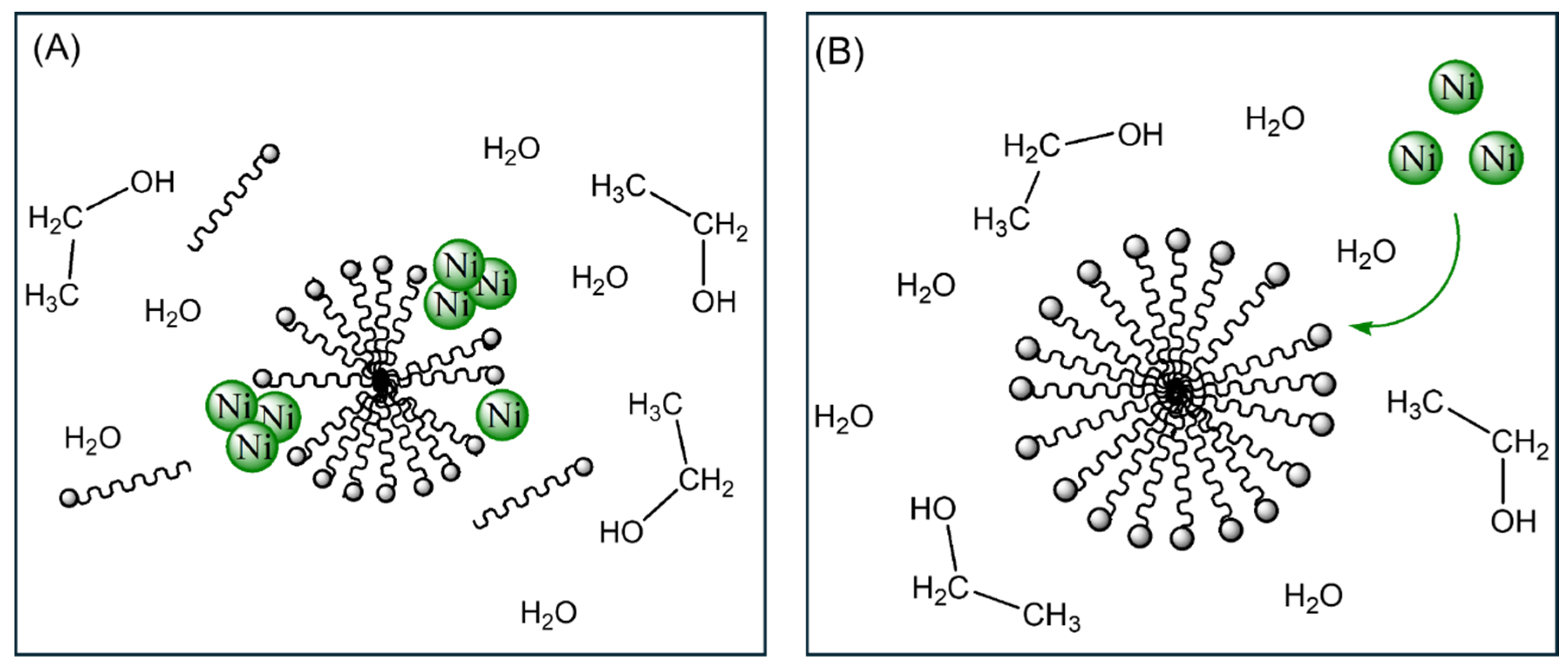
2.1.1. Synthesis of Catalyst A (Ni/Si-MCM-41_A)
2.1.2. Synthesis of Catalyst B (Ni/Si-MCM-41_B)
2.2. Preparation of Granulated Catalysts
2.3. Catalytic Efficiency in DR
2.4. Catalysts Characterization
3. Results and Discussion
3.1. Catalysts Characterization
3.2. Dry Reforming Results
4. Conclusions
Author Contributions
Funding
Data Availability Statement
Acknowledgments
Conflicts of Interest
References
- Bairrão, D.; Soares, J.; Almeida, J.; Franco, J.F.; Vale, Z. Green Hydrogen and Energy Transition: Current State and Prospects in Portugal. Energies 2023, 16, 551. [Google Scholar] [CrossRef]
- Espegren, K.; Damman, S.; Pisciella, P.; Graabak, I.; Tomasgard, A. The Role of Hydrogen in the Transition from a Petroleum Economy to a Low-Carbon Society. Int. J. Hydrogen Energy 2021, 46, 23125–23138. [Google Scholar] [CrossRef]
- Delparish, A.; Avci, A.K. Intensified Catalytic Reactors for Fischer-Tropsch Synthesis and for Reforming of Renewable Fuels to Hydrogen and Synthesis Gas. Fuel Process. Technol. 2016, 151, 72–100. [Google Scholar] [CrossRef]
- Aravindan, M.; Hariharan, V.S.; Narahari, T.; Kumar, A.; Madhesh, K.; Kumar, P.; Prabakaran, R. Fuelling the Future: A Review of Non-Renewable Hydrogen Production and Storage Techniques. Renew. Sustain. Energy Rev. 2023, 188, 113791. [Google Scholar] [CrossRef]
- Amin, M.; Shah, H.H.; Fareed, A.G.; Khan, W.U.; Chung, E.; Zia, A.; Rahman Farooqi, Z.U.; Lee, C. Hydrogen Production through Renewable and Non-Renewable Energy Processes and Their Impact on Climate Change. Int. J. Hydrogen Energy 2022, 47, 33112–33134. [Google Scholar] [CrossRef]
- Zhang, K.; Jin, Z.; Liu, Q.; Liu, L. Novel Green Hydrogen—Fossil Fuel Dehydrogenation. Fundam. Res. 2024. [Google Scholar] [CrossRef]
- Ishaq, H.; Dincer, I.; Crawford, C. A Review on Hydrogen Production and Utilization: Challenges and Opportunities. Int. J. Hydrogen Energy 2022, 47, 26238–26264. [Google Scholar] [CrossRef]
- Guan, D.; Wang, B.; Zhang, J.; Shi, R.; Jiao, K.; Li, L.; Wang, Y.; Xie, B.; Zhang, Q.; Yu, J.; et al. Hydrogen Society: From Present to Future. Energy Environ. Sci. 2023, 16, 4926–4943. [Google Scholar] [CrossRef]
- Abdin, Z.; Zafaranloo, A.; Rafiee, A.; Mérida, W.; Lipiński, W.; Khalilpour, K.R. Hydrogen as an Energy Vector. Renew. Sustain. Energy Rev. 2020, 120, 109620. [Google Scholar] [CrossRef]
- Nikolaidis, P.; Poullikkas, A. A Comparative Overview of Hydrogen Production Processes. Renew. Sustain. Energy Rev. 2017, 67, 597–611. [Google Scholar] [CrossRef]
- Acar, C.; Dincer, I. Review and Evaluation of Hydrogen Production Options for Better Environment. J. Clean. Prod. 2019, 218, 835–849. [Google Scholar] [CrossRef]
- Fernandes, D.J.; Ferreira, A.F.; Fernandes, E.C. Biogas and Biomethane Production Potential via Anaerobic Digestion of Manure: A Case Study of Portugal. Renew. Sustain. Energy Rev. 2023, 188, 113846. [Google Scholar] [CrossRef]
- Abatzoglou, N.; Boivin, S. A Review of Biogas Purification Processes. Biofuels Bioprod. Biorefining 2009, 3, 42–71. [Google Scholar] [CrossRef]
- Hajizadeh, A.; Mohamadi-Baghmolaei, M.; Cata Saady, N.M.; Zendehboudi, S. Hydrogen Production from Biomass through Integration of Anaerobic Digestion and Biogas Dry Reforming. Appl. Energy 2022, 309, 118442. [Google Scholar] [CrossRef]
- EPE (Empresa de Pesquisa Energética). Análise de Conjuntura Dos Biocombustíveis. 2021. Available online: https://www.epe.gov.br/sites-pt/publicacoes-dados-abertos/publicacoes/PublicacoesArquivos/publicacao-688/NT-EPE-DPG-SDB-2022-02_Analise_de_Conjuntura_dos_Biocombustiveis_2021.pdf (accessed on 20 July 2024).
- Gao, Y.; Jiang, J.; Meng, Y.; Yan, F.; Aihemaiti, A. A Review of Recent Developments in Hydrogen Production via Biogas Dry Reforming. Energy Convers. Manag. 2018, 171, 133–155. [Google Scholar] [CrossRef]
- Al-Fatesh, A.S.; Atia, H.; Abu-Dahrieh, J.K.; Ibrahim, A.A.; Eckelt, R.; Armbruster, U.; Abasaeed, A.E.; Fakeeha, A.H. Hydrogen Production from CH4 Dry Reforming over Sc Promoted Ni/MCM-41. Int. J. Hydrogen Energy 2019, 44, 20770–20781. [Google Scholar] [CrossRef]
- Jung, S.; Lee, J.; Moon, D.H.; Kim, K.-H.; Kwon, E.E. Upgrading Biogas into Syngas through Dry Reforming. Renew. Sustain. Energy Rev. 2021, 143, 110949. [Google Scholar] [CrossRef]
- Abdulrasheed, A.; Jalil, A.A.; Gambo, Y.; Ibrahim, M.; Hambali, H.U.; Shahul Hamid, M.Y. A Review on Catalyst Development for Dry Reforming of Methane to Syngas: Recent Advances. Renew. Sustain. Energy Rev. 2019, 108, 175–193. [Google Scholar] [CrossRef]
- Zhang, J.; Li, F. Coke-Resistant Ni@SiO2 Catalyst for Dry Reforming of Methane. Appl. Catal. B 2015, 176–177, 513–521. [Google Scholar] [CrossRef]
- Zhang, J.; Xin, Z.; Meng, X.; Tao, M. Synthesis, Characterization and Properties of Anti-Sintering Nickel Incorporated MCM-41 Methanation Catalysts. Fuel 2013, 109, 693–701. [Google Scholar] [CrossRef]
- Abdelhamid, H.N. A Review on Hydrogen Generation from the Hydrolysis of Sodium Borohydride. Int. J. Hydrogen Energy 2021, 46, 726–765. [Google Scholar] [CrossRef]
- Aguiar, M.; Cazula, B.B.; Saragiotto Colpini, L.M.; Borba, C.E.; Alves da Silva, F.; Noronha, F.B.; Alves, H.J. Si-MCM-41 Obtained from Different Sources of Silica and Its Application as Support for Nickel Catalysts Used in Dry Reforming of Methane. Int. J. Hydrogen Energy 2019, 44, 32003–32018. [Google Scholar] [CrossRef]
- Cazula, B.; da Fonseca, R.; Marinho, A.L.; Noronha, F.; Arroyo, P.A.; Yamamoto, C.; Brackmann, R.; José Alves, H. Performance Study of Ni/Si-MCM-41 Catalysts, Synthesized with Different Silica Sources, and Their Application on Methane Dry Reform to Produce Green Hydrogen. J. Braz. Chem. Soc. 2024, 35, e-20230133. [Google Scholar] [CrossRef]
- Grün, M.; Unger, K.K.; Matsumoto, A.; Tsutsumi, K. Novel Pathways for the Preparation of Mesoporous MCM-41 Materials: Control of Porosity and Morphology. Microporous Mesoporous Mater. 1999, 27, 207–216. [Google Scholar] [CrossRef]
- Cazula, B.B.; Oliveira, L.G.; Machado, B.; Alves, H.J. Optimization of Experimental Conditions for the Synthesis of Si-MCM-41 Molecular Sieves Using Different Methods and Silica Sources. Mater. Chem. Phys. 2021, 266, 124553. [Google Scholar] [CrossRef]
- Zhuang, J.; Yan, S.; Zhang, P.; Liu, X.; Zhao, Y.; Yu, Y.; Wang, Y.; Zhao, Q.; Wu, H.; Zhu, X.; et al. Regulating the States of Ni Species by Controlling the Silanols of MCM-41 Support to Promote the Hydrogenation of Maleic Anhydride. Fuel 2023, 335, 127030. [Google Scholar] [CrossRef]
- Oliveira, L.G.; Machado, B.; Pereira de Souza, L.; Gosch Corrêa, G.C.; Polinarski, M.A.; Cavalcanti Trevisan, S.V.; Borba, C.E.; Brackmann, R.; Alves, H.J. Dry Reforming of Biogas in a Pilot Unit: Scale-up of Catalyst Synthesis and Green Hydrogen Production. Int. J. Hydrogen Energy 2022, 47, 35608–35625. [Google Scholar] [CrossRef]
- Zempulski, D.A.; Postaue, N.; Stevanato, N.; Alves, H.J.; Silva, C. Study of the Operational Conditions for Ethyl Esters Production Using Residual Frying Oil and KF/Clay Catalyst in a Continuous System. Grasas y Aceites 2022, 73, e453. [Google Scholar] [CrossRef]
- Ayodele, B.V.; Khan, M.R.; Cheng, C.K. Catalytic Performance of Ceria-Supported Cobalt Catalyst for CO-Rich Hydrogen Production from Dry Reforming of Methane. Int. J. Hydrogen Energy 2016, 41, 198–207. [Google Scholar] [CrossRef]
- Charisiou, N.D.; Siakavelas, G.; Papageridis, K.N.; Baklavaridis, A.; Tzounis, L.; Avraam, D.G.; Goula, M.A. Syngas Production via the Biogas Dry Reforming Reaction over Nickel Supported on Modified with CeO2 and/or La2O3 Alumina Catalysts. J. Nat. Gas Sci. Eng. 2016, 31, 164–183. [Google Scholar] [CrossRef]
- Wen, T.; Zhao, Y.; Jiao, X.; Zhang, Q.; Zhang, T.; Zhang, X.; Qu, J.; Dong, Y.; Song, S. High-Performance Nickel/Iron Catalysts for Oxygen Evolution in PH-near-Neutral Borate Electrolyte Synthesized by Mechanochemical Approach. J. Alloys Compd. 2022, 898, 162845. [Google Scholar] [CrossRef]
- Afzal, M.; Theocharis, C.R.; Karim, S. Temperature Programmed Reduction of Silica Supported Nickel Catalysts. Colloid Polym. Sci. 1993, 271, 1100–1105. [Google Scholar] [CrossRef]
- Li, Y.; Wang, J.; Ding, C.; Ma, L.; Xue, Y.; Guo, J.; Wang, S.; Meng, Y.; Zhang, K.; Liu, P. Effect of Cobalt Addition on the Structure and Properties of Ni–MCM-41 for the Partial Oxidation of Methane to Syngas. RSC Adv. 2019, 9, 25508–25517. [Google Scholar] [CrossRef] [PubMed]
- Ding, C.; Wang, J.; Li, Y.; Ma, Q.; Ma, L.; Guo, J.; Ma, Z.; Liu, P.; Zhang, K. The Role of Active Sites Location in Partial Oxidation of Methane to Syngas for MCM-41 Supported Ni Nanoparticles. Catalysts 2019, 9, 606. [Google Scholar] [CrossRef]
- Hasani Estalkhi, M.; Yousefpour, M.; Koohestan, H.; Taherian, Z. Catalytic Evaluation of Ni–3%Sr-/MCM-41 in Dry and Steam Reforming of Methane. Int. J. Hydrogen Energy 2024, 68, 1344–1351. [Google Scholar] [CrossRef]
- Chotirach, M.; Tungasmita, S.; Nuntasri Tungasmita, D.; Tantayanon, S. Titanium Nitride Promoted Ni-Based SBA-15 Catalyst for Dry Reforming of Methane. Int. J. Hydrogen Energy 2018, 43, 21322–21332. [Google Scholar] [CrossRef]
- Bagabas, A.; Al-Fatesh, A.S.; Kasim, S.O.; Arasheed, R.; Ibrahim, A.A.; Ashamari, R.; Anojaidi, K.; Fakeeha, A.H.; Abu-Dahrieh, J.K.; Abasaeed, A.E. Optimizing MgO Content for Boosting γ-Al2O3-Supported Ni Catalyst in Dry Reforming of Methane. Catalysts 2021, 11, 1233. [Google Scholar] [CrossRef]
- Lee, J.-H.; You, Y.-W.; Ahn, H.-C.; Hong, J.-S.; Kim, S.-B.; Chang, T.-S.; Suh, J.-K. The Deactivation Study of Co–Ru–Zr Catalyst Depending on Supports in the Dry Reforming of Carbon Dioxide. J. Ind. Eng. Chem. 2014, 20, 284–289. [Google Scholar] [CrossRef]
- Owgi, A.H.K.; Jalil, A.A.; Aziz, M.A.A.; Alhassan, M.; Hambali, H.U.; Nabgan, W.; Saravanan, R.; Hatta, A.H. Effect of Promoters (Ce, Sr, Cs, and Sm) on the Activity and Coke Formation of FSA Support Ni in the Dry Reforming of Methane. Fuel 2023, 340, 127592. [Google Scholar] [CrossRef]
- Li, M.; Liu, W.; Mao, Y.; Liu, K.; Zhang, L.; Cao, Z.; Ma, Q.; Ye, L.; Peng, H. Design Dual Confinement Ni@S-1@SiO2 Catalyst with Enhanced Carbon Resistance for Methane Dry Reforming. Int. J. Hydrogen Energy 2024, 83, 79–88. [Google Scholar] [CrossRef]
- Song, J.; Duan, X.; Zhang, W. Methane Dry Reforming over Mesoporous La2O3 Supported Ni Catalyst for Syngas Production. Microporous Mesoporous Mater. 2021, 310, 110587. [Google Scholar] [CrossRef]
- Taherian, Z.; Khataee, A.; Orooji, Y. Facile Synthesis of Yttria-Promoted Nickel Catalysts Supported on MgO-MCM-41 for Syngas Production from Greenhouse Gases. Renew. Sustain. Energy Rev. 2020, 134, 110130. [Google Scholar] [CrossRef]


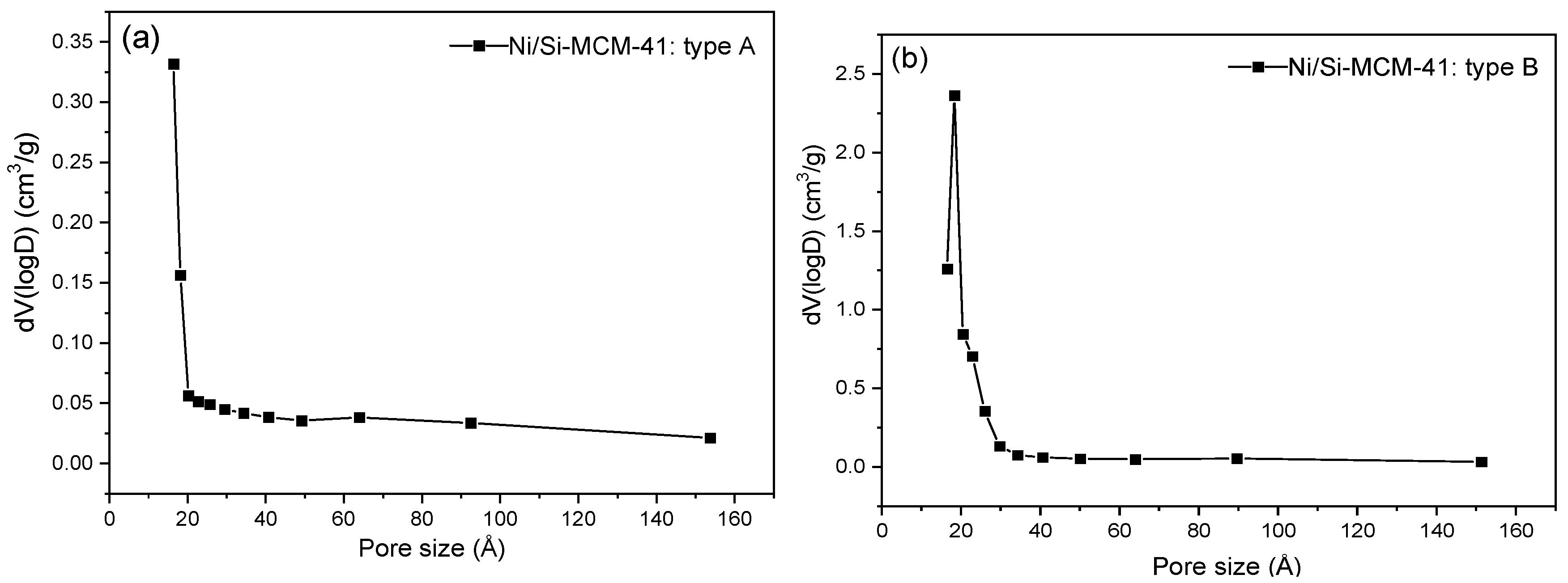
| Catalyst | Surface Area (m2 g−1) | Total Pore Volume (cm3 g−1) | Pore Size (Å) |
|---|---|---|---|
| A | 204.27 | 0.058 | 16.38 |
| B | 412.56 | 0.309 | 18.31 |
| Catalyst | Surface Area (m2/g) | Reactor | Temperature (°C) | Catalyst Mass (g) | CH4 Conversion (%) | H2/CO | Reference |
|---|---|---|---|---|---|---|---|
| Sr/Ni/MCM-41 | 212.3 | quartz | 700 | 0.2 | 73.3 | 0.88 | Estalkhi et al., 2024 [36] |
| 10Ni/SBA-15 | 592 | stainless steel | 700 | 0.05 | 70.4 | 0.85 | Chotirach et al., 2018 [37] |
| 5Ni2Mg3SiAl | 230.15 | stainless steel | 700 | 0.10 | 86 | 0.95 | Bagabas et al., 2021 [38] |
| Co–Ru–Zr/SiO2 Co–Ru–Zr/γ-Al2O3 Co–Ru–Zr/MgO | 108.4 126.9 36.82 | quartz | 800 | 0.2 | 90 92 80 | 0.90 0.91 0.87 | Lee et al., 2014 [39] |
| Cs-Ni/FSA | 152.74 | stainless steel | 850 | 0.2 | 93 | 0.5 | Owgi et al., 2023 [40] |
| Ni@S-1@SiO2 | 630 | quartz | 800 | 0.05 | 93.7 | - | Li et al., 2024 [41] |
| 5%Ni/La2O3-KIT-6 | 55.3 | quartz | 700 | 0.1 | ~70 | ~0.8 | Song et al., 2021 [42] |
| 2Y2O3–NiO/MgO-MCM-41 | 445.7 | quartz | 750 | 0.2 | 79 | 0.85 | Taherian et al., 2020 [43] |
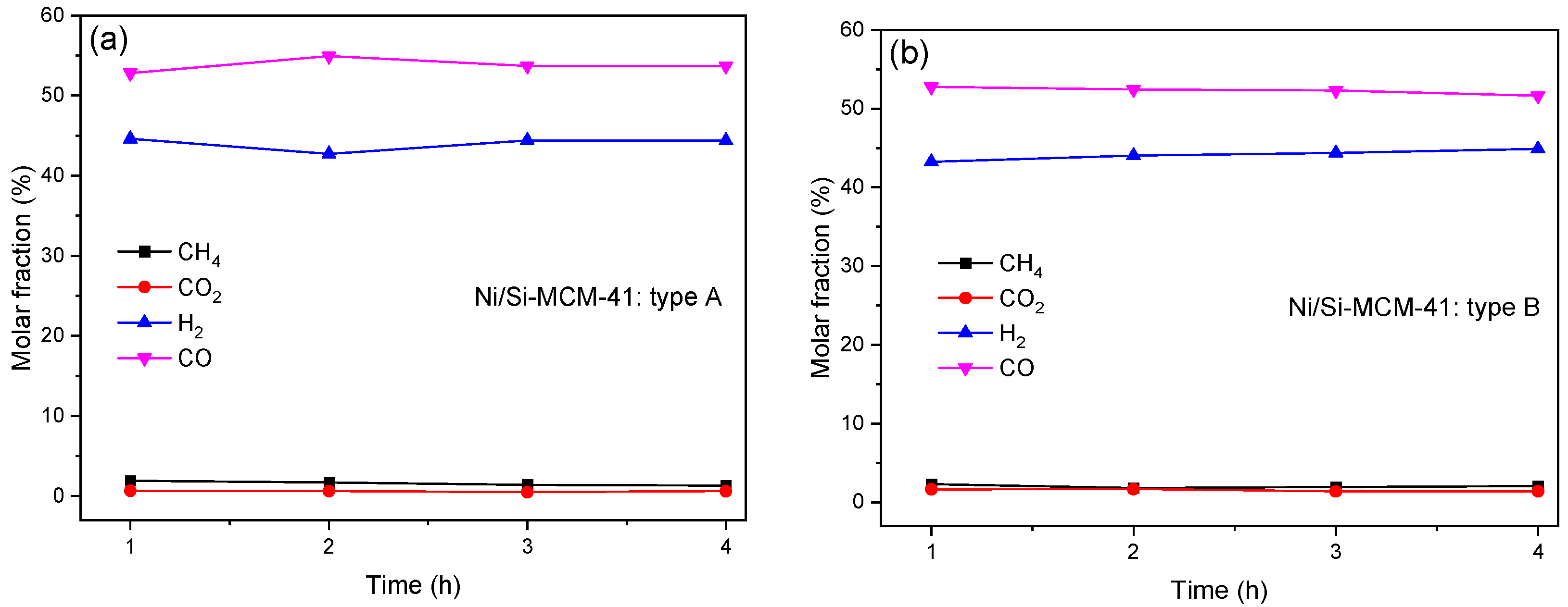
| This work | |||||||
| Ni/SiMCM-41_A | 204.2 | stainless steel | 800 | 3 | 97 | 0.82 | |
| Ni/SiMCM-41_B | 412.5 | stainless steel | 800 | 3 | 96 | 0.84 | |
Disclaimer/Publisher’s Note: The statements, opinions and data contained in all publications are solely those of the individual author(s) and contributor(s) and not of MDPI and/or the editor(s). MDPI and/or the editor(s) disclaim responsibility for any injury to people or property resulting from any ideas, methods, instructions or products referred to in the content. |
© 2024 by the authors. Licensee MDPI, Basel, Switzerland. This article is an open access article distributed under the terms and conditions of the Creative Commons Attribution (CC BY) license (https://creativecommons.org/licenses/by/4.0/).
Share and Cite
Oliveira, L.G.; do Nascimento, C.T.; Cazula, B.B.; Tait, A.; de Oliveira, C.d.J.; Souza, G.E.Q.; Gasparrini, L.J.; Alencar, Á.d.O.; Ritter, G.; Jorge, N.N.; et al. Nickel-Stage Addition in Si-MCM-41 Synthesis for Renewable Hydrogen Production. Processes 2024, 12, 1836. https://doi.org/10.3390/pr12091836
Oliveira LG, do Nascimento CT, Cazula BB, Tait A, de Oliveira CdJ, Souza GEQ, Gasparrini LJ, Alencar ÁdO, Ritter G, Jorge NN, et al. Nickel-Stage Addition in Si-MCM-41 Synthesis for Renewable Hydrogen Production. Processes. 2024; 12(9):1836. https://doi.org/10.3390/pr12091836
Chicago/Turabian StyleOliveira, Lígia Gomes, Cleuciane Tillvitz do Nascimento, Bárbara Bulhões Cazula, Anabelle Tait, Carlos de Jesus de Oliveira, Guilherme Emanuel Queiros Souza, Lázaro José Gasparrini, Áquila de Oliveira Alencar, Gabriela Ritter, Natália Neumann Jorge, and et al. 2024. "Nickel-Stage Addition in Si-MCM-41 Synthesis for Renewable Hydrogen Production" Processes 12, no. 9: 1836. https://doi.org/10.3390/pr12091836