
Preparation and Properties of Waterborne Polyurethane/Carbon Nanotube/Graphene/Cellulose Nanofiber Composites


Abstract
:1. Introduction
2. Experimental Section
2.1. Materials
2.2. Experimental Steps
2.2.1. Graphene Pretreatment
2.2.2. Preparation of Waterborne Polyurethane Composites with Carbon Nanotubes
2.2.3. Preparation of Graphene/Carbon Nanotube Waterborne Polyurethane Composites
2.2.4. Preparation of Cellulose/Graphene/Carbon Nanotube Waterborne Polyurethane Composites
2.3. Characterization
3. Results and Discussion
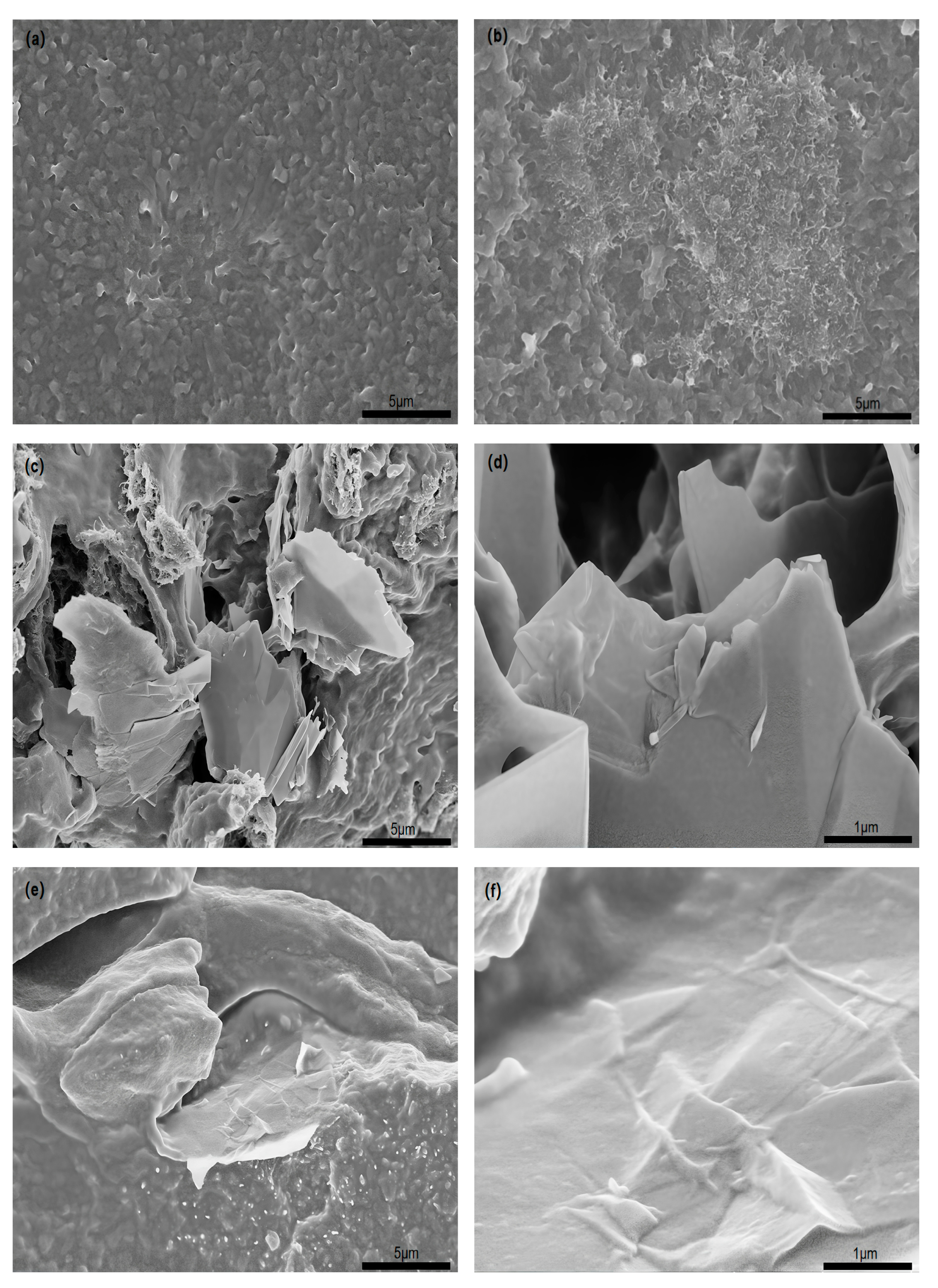
3.1. SEM
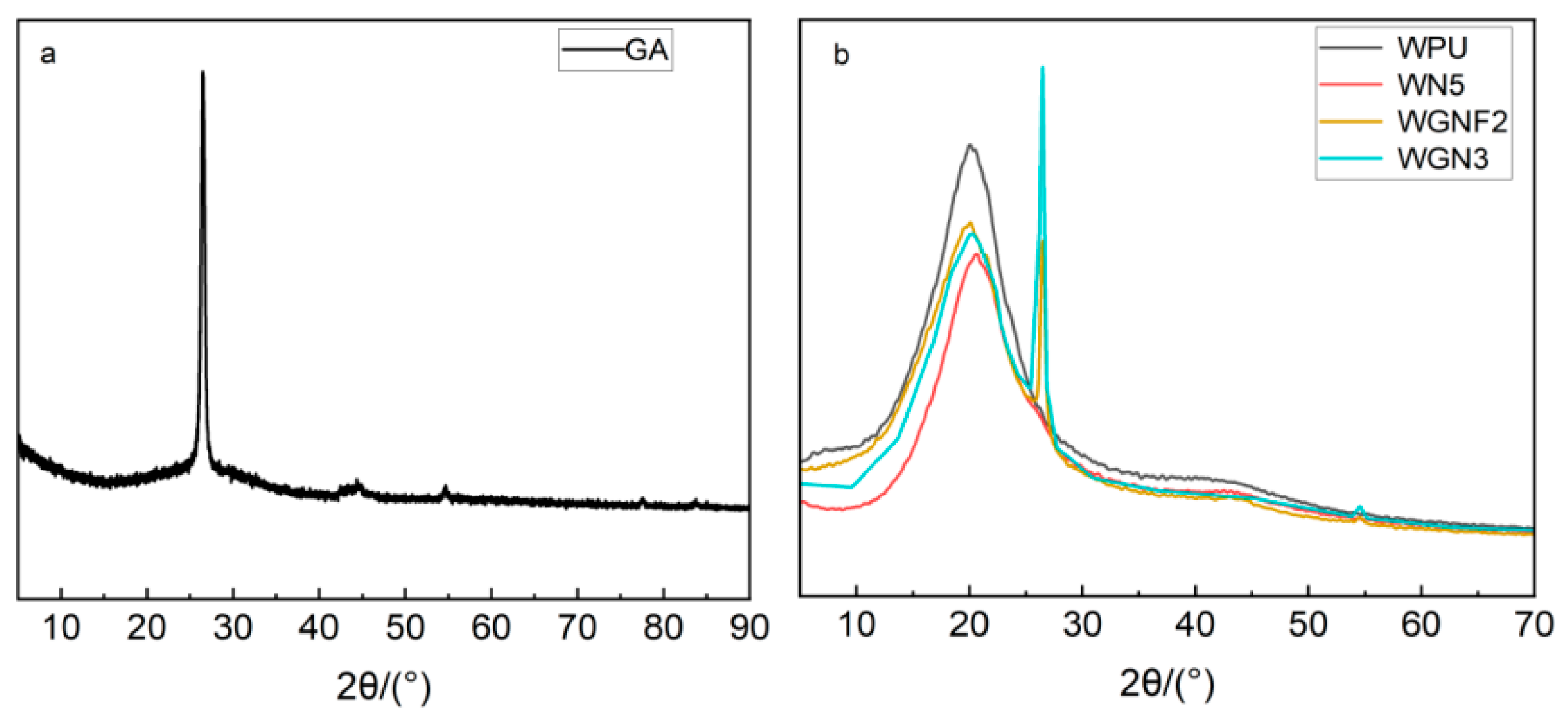
3.2. XRD
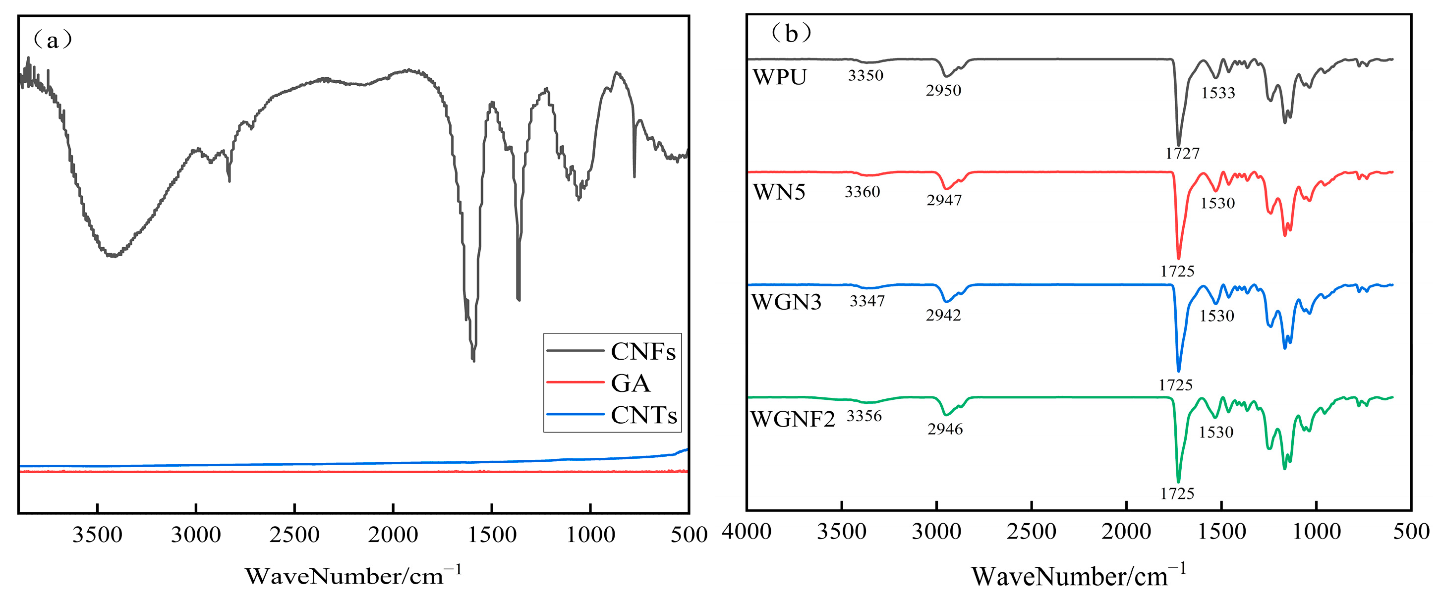
3.3. FT-IR
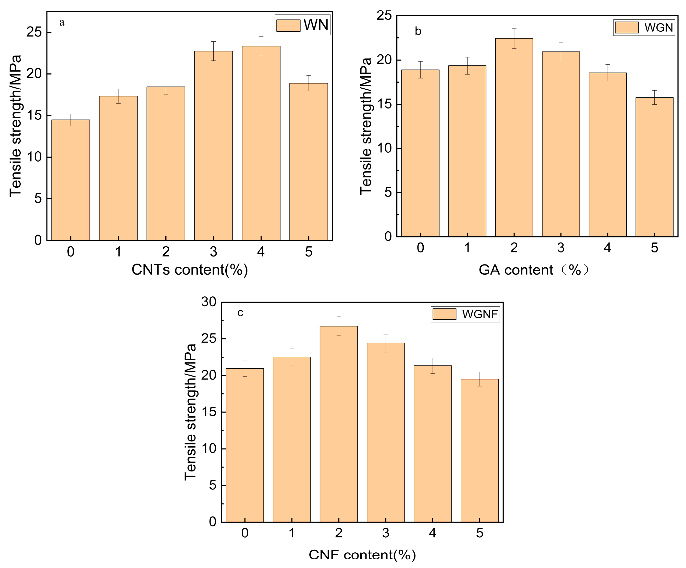
3.4. Mechanical Characteristics
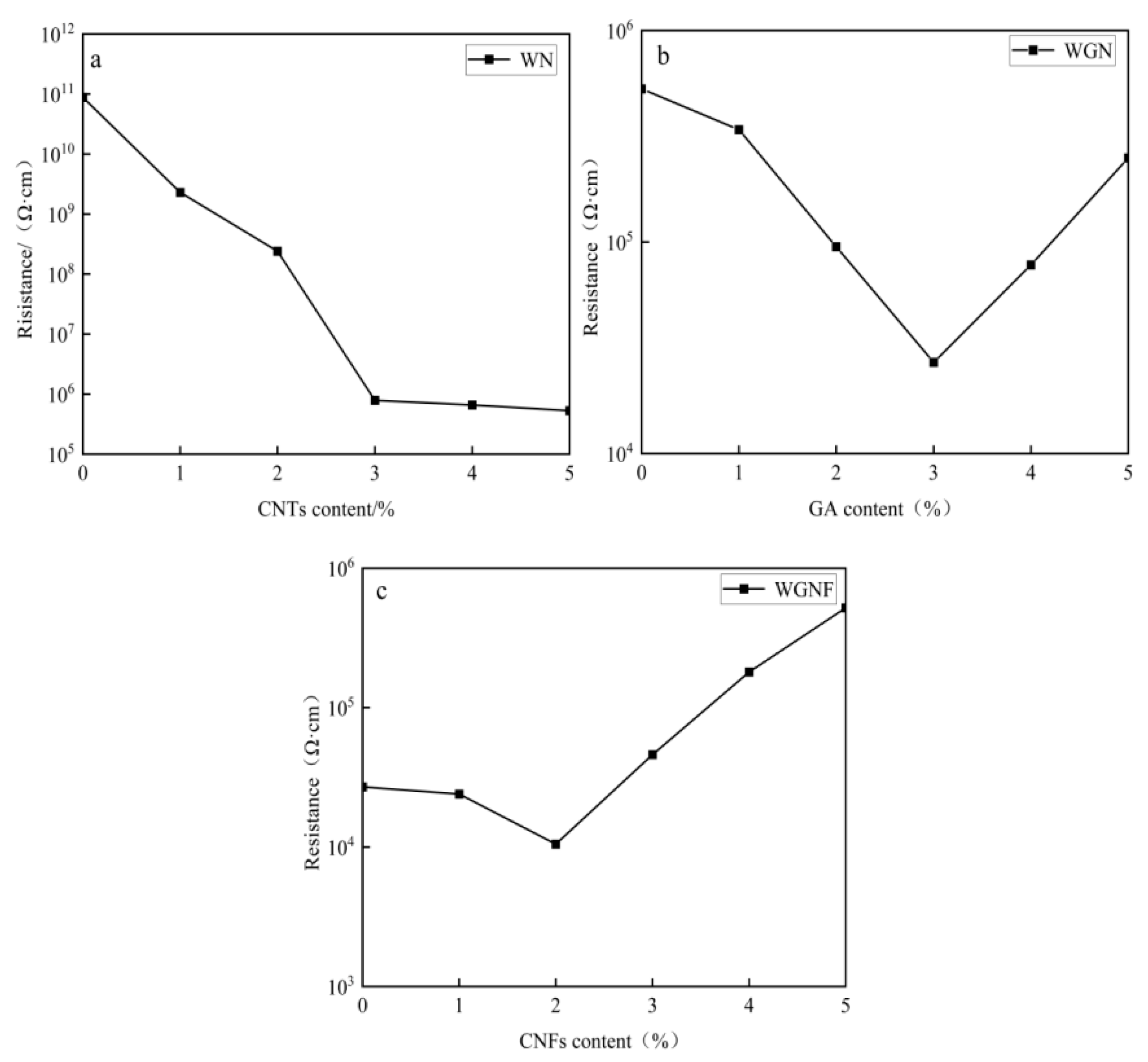
3.5. Electrical Conductivity
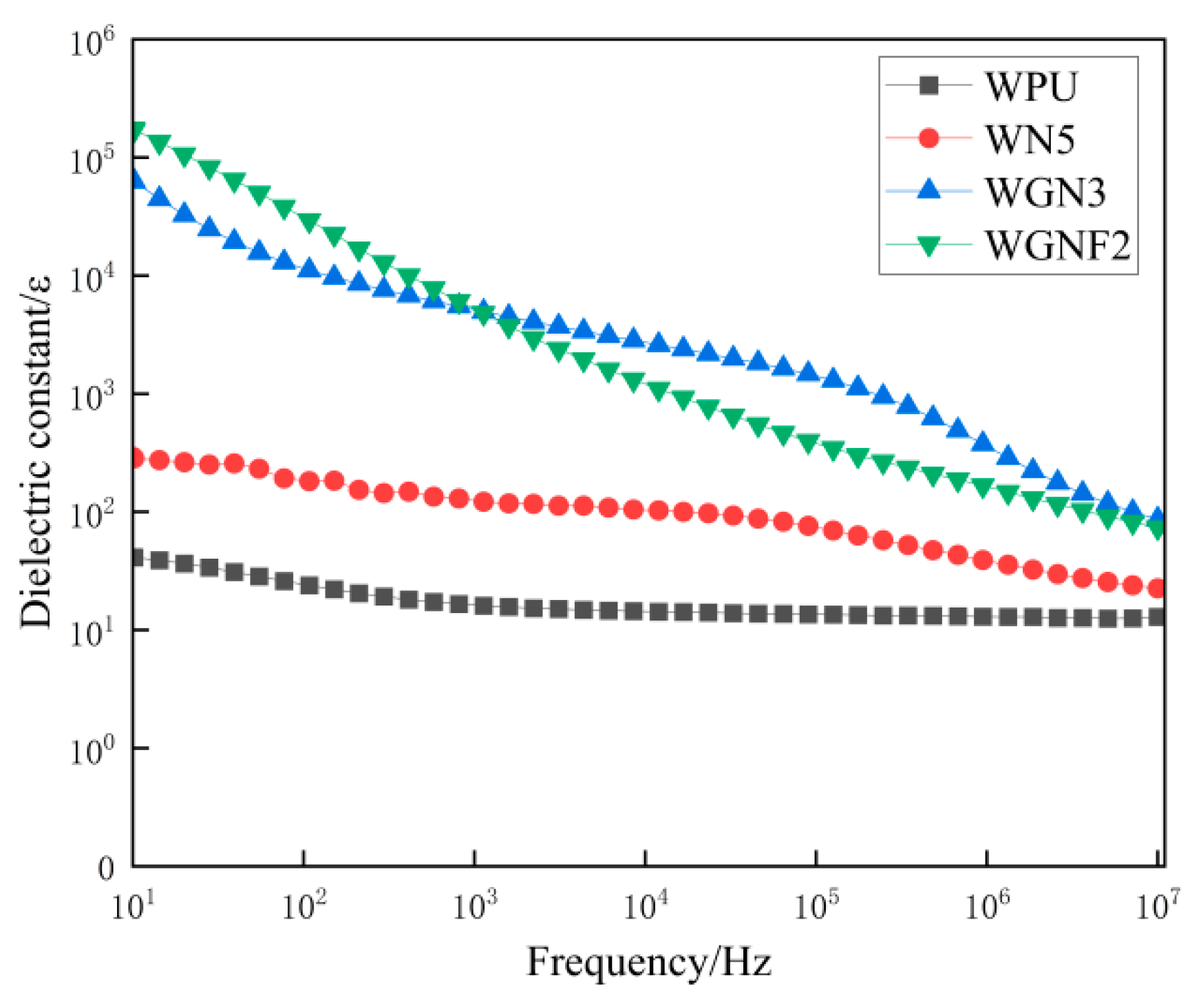
3.6. Dielectric Properties
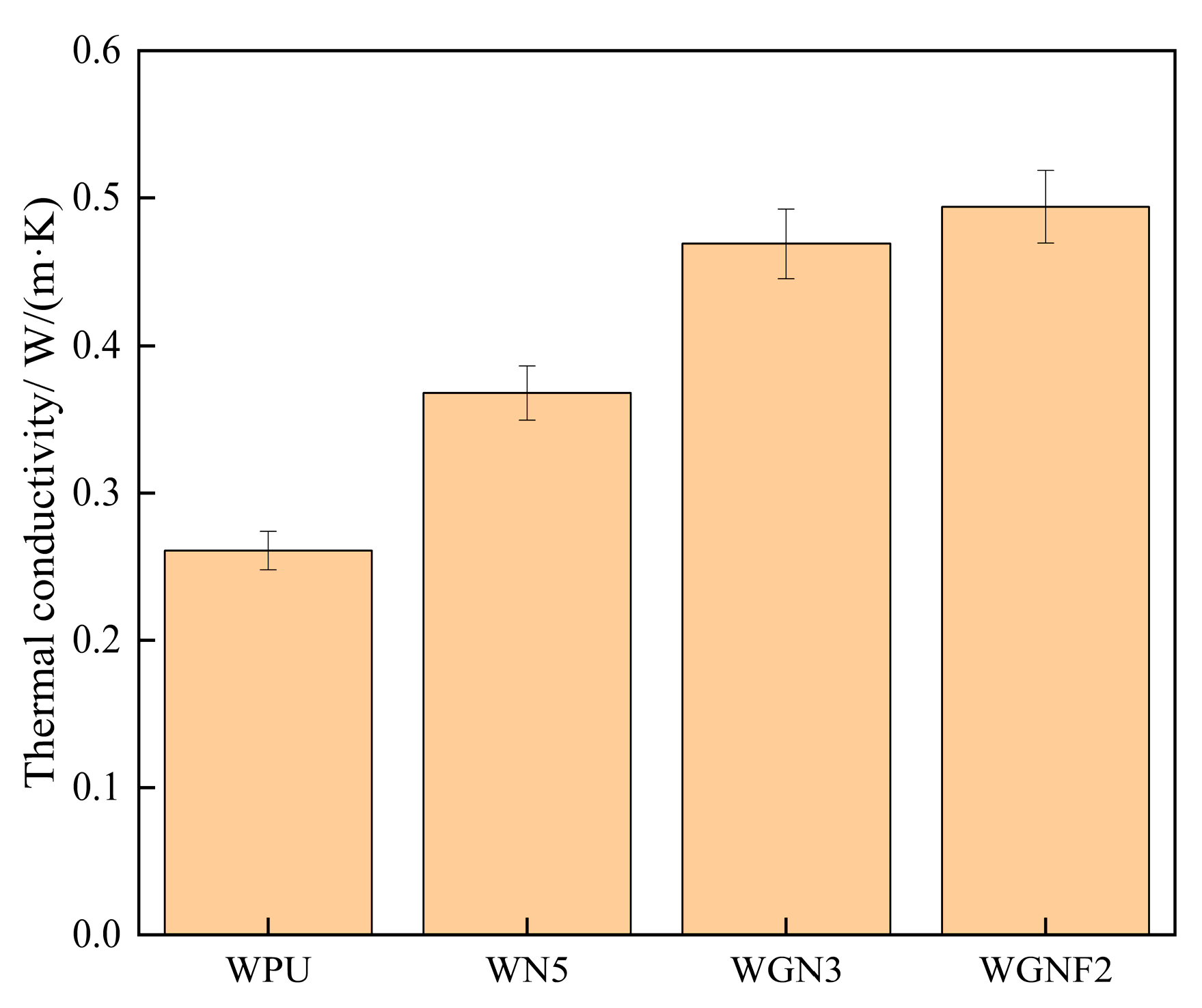
3.7. Thermal Conductivity
4. Conclusions
Author Contributions
Funding
Institutional Review Board Statement
Informed Consent Statement
Data Availability Statement
Conflicts of Interest
References
- Xiong, H.; Ling, S.; Li, Y.; Duan, F.; Zhu, H.; Lu, S.; Du, M. Flexible and recyclable bio-based transient resistive memory enabled by self-healing polyimine membrane. J. Colloid Interface Sci. 2022, 608, 1126–1134. [Google Scholar] [CrossRef]
- Sahoo, S.; Sinha, A.; Koshi, N.A.; Lee, S.-C.; Bhattacharjee, S.; Muralidharan, B. Silicene: An excellent material for flexible electronics. J. Phys. D Appl. Phys. 2022, 55, 425301. [Google Scholar] [CrossRef]
- Zhou, X.; Guo, W.; Sun, Q.; Sun, L.; Peng, P. Laser Writing of Cu–Ag Alloy Flexible Electrodes with Excellent Oxidation and Electrochemical Migration Resistances. ACS Appl. Electron. Mater. 2023, 5, 3780–3789. [Google Scholar] [CrossRef]
- Lu, W.; Zhang, Y.; Zhou, J.; Sun, D.; Li, H. Effect of MXene fillers on the electrical conductivity of Ag-coated Cu conductive adhesives. Ceram. Int. 2023, 49, 9978–9984. [Google Scholar] [CrossRef]
- Huang, L.; Chen, J.; Xu, Y.; Hu, D.; Cui, X.; Shi, D.; Zhu, Y. Three-dimensional light-weight piezoresistive sensors based on conductive polyurethane sponges coated with hybrid CNT/CB nanoparticles. Appl. Surf. Sci. 2021, 548, 149268. [Google Scholar] [CrossRef]
- Zhang, R.-Q.; Wang, L.-B.; Bai, R.-X.; Luo, Y.-L.; Xu, F.; Chen, Y.-S. Sensitive conductive polymer nanocomposites from multiwalled carbon nanotube coated with polypyrrole and hydroxyl-terminated poly (butadiene-co-acrylonitile) polyurethane for detection of chloroform vapor. Compos. Part B 2019, 173, 106894. [Google Scholar] [CrossRef]
- Park, K. Wearable sensor for forearm motion detection using a carbon-based conductive layer-polymer composite film. Sensors 2022, 22, 2236. [Google Scholar] [CrossRef]
- Vu, C.C.; Nguyen, T.T.; Kim, S.; Kim, J. Effects of 3D printing-line directions for stretchable sensor performances. Materials 2021, 14, 1791. [Google Scholar] [CrossRef]
- Lv, B.; Chen, X.; Liu, C. A highly sensitive piezoresistive pressure sensor based on graphene oxide/polypyrrole@ polyurethane sponge. Sensors 2020, 20, 1219. [Google Scholar] [CrossRef]
- Tao, J.-R.; Luo, C.-L.; Huang, M.-L.; Weng, Y.-X.; Wang, M. Construction of unique conductive networks in carbon nanotubes/polymer composites via poly (ε-caprolactone) inducing partial aggregation of carbon nanotubes for microwave shielding enhancement. Compos. Part A 2023, 164, 107304. [Google Scholar] [CrossRef]
- Wang, Y.; Wang, X.; Cao, X.; Gong, S.; Xie, Z.; Li, T.; Wu, C.; Zhu, Z.; Li, Z. Effect of nano-scale Cu particles on the electrical property of CNT/polymer nanocomposites. Compos. Part A 2021, 143, 106325. [Google Scholar] [CrossRef]
- Xu, Y.-T.; Wang, Y.; Zhou, C.-G.; Sun, W.-J.; Dai, K.; Tang, J.-H.; Lei, J.; Yan, D.-X.; Li, Z.-M. An electrically conductive polymer composite with a co-continuous segregated structure for enhanced mechanical performance. J. Mater. Chem. 2020, 8, 11546–11554. [Google Scholar] [CrossRef]
- Lai, F.; Zhao, L.; Zou, J.; Zhang, P. High positive temperature coefficient effect of resistivity in conductive polystyrene/polyurethane composites with ultralow percolation threshold of MWCNTs via interpenetrating structure. React. Funct. Polym. 2020, 151, 104562. [Google Scholar] [CrossRef]
- Hajian, A.; Lindstrom, S.B.; Pettersson, T.; Hamedi, M.M.; Wagberg, L. Understanding the dispersive action of nanocellulose for carbon nanomaterials. Nano Lett. 2017, 17, 1439–1447. [Google Scholar] [CrossRef] [PubMed]
- Li, J.; Wang, R.; Li, L. Influence of cellulose ethers structure on mechanical strength of calcium sulphoaluminate cement mortar. Constr. Build. Mater. 2021, 303, 124514. [Google Scholar] [CrossRef]
- Patel, D.K.; Ganguly, K.; Dutta, S.D.; Patil, T.V.; Lim, K.-T. Cellulose nanocrystals vs. cellulose nanospheres: A comparative study of cytotoxicity and macrophage polarization potential. Carbohydr. Polym. 2023, 303, 120464. [Google Scholar] [CrossRef]
- Piaia, L.; Pittella, C.Q.P.; Souza, S.S.d.; Berti, F.V.; Porto, L.M. Incorporation of Aloe vera extract in bacterial nanocellulose membranes. Polimeros 2022, 32, e2022002. [Google Scholar] [CrossRef]
- Yuan, Y.; Chen, H. Preparation and characterization of a biodegradable starch-based antibacterial film containing nanocellulose and polyhexamethylene biguanide. Food Packag. Shelf Life 2021, 30, 100718. [Google Scholar] [CrossRef]
- Liang, G.; Qi, Y.; Gong, R.; Hu, Y.; Yao, F.; Liu, Y.; Liu, B.; Zhao, Y.; Dai, Y.; Dong, X. Nanocellulose-reinforced polyurethane as flexible coating for cork floor. Prog. Org. Coat. 2023, 178, 107480. [Google Scholar] [CrossRef]
- Zhang, S.; Sun, K.; Liu, H.; Chen, X.; Zheng, Y.; Shi, X.; Zhang, D.; Mi, L.; Liu, C.; Shen, C. Enhanced piezoresistive performance of conductive WPU/CNT composite foam through incorporating brittle cellulose nanocrystal. Chem. Eng. J. 2020, 387, 124045. [Google Scholar] [CrossRef]
- Yan, Q.; Xie, W.; Zhou, M.; Fu, H. An ultrasensitive and highly compressive piezoresistive sensor based on a biopolyol-reinforced polyurethane sponge coated with silver nanoparticles and carbon nanotubes/cellulose nanocrystals. J. Mater. Chem. 2020, 8, 16603–16614. [Google Scholar] [CrossRef]
- Fei, Y.; Chen, F.; Fang, W.; Hejna, A.; Xu, L.; Liu, T.; Zhong, M.; Yang, J.; Kuang, T. Conductive thermoplastic polyurethane nanocomposite foams derived from a cellulose/MWCNTs aerogel framework: Simultaneous enhancement of piezoresistance, strength, and endurance. J. Mater. Chem. 2021, 9, 13103–13114. [Google Scholar] [CrossRef]
- Wu, Y.; Xu, L.; Xia, C.; Gan, L. High performance flexible and antibacterial strain sensor based on silver-carbon nanotubes coated cellulose/polyurethane nanofibrous membrane: Cellulose as reinforcing polymer blend and polydopamine as compatibilizer. Int. J. Biol. Macromol. 2022, 223, 184–192. [Google Scholar] [CrossRef] [PubMed]
- Yang, Y.; Yi, T.; Liu, Y.; Zhao, H.; Liang, C. Design of a highly sensitive reduced graphene oxide/graphene oxide@ cellulose acetate/thermoplastic polyurethane flexible sensor. Sensors 2022, 22, 3281. [Google Scholar] [CrossRef] [PubMed]
- Zhao, J.; Wang, Z.; Xu, S.; Wang, H.; Li, Y.; Fang, C. Flexible bilayer Ti3C2Tx MXene/cellulose nanocrystals/waterborne polyurethane composite film with excellent mechanical properties for electromagnetic interference shielding. Colloids Surf. A 2023, 669, 131556. [Google Scholar] [CrossRef]
- Miao, C.; Cui, X.; Sun, J.; Lu, S.; Liu, X. High flexibility and wide sensing range human health monitoring sensors based on Ti3C2Tx MXene/CNTs/WPU/CNFs composite ink film. Mater. Sci. Semicond. Process. 2023, 158, 107384. [Google Scholar] [CrossRef]
Disclaimer/Publisher’s Note: The statements, opinions and data contained in all publications are solely those of the individual author(s) and contributor(s) and not of MDPI and/or the editor(s). MDPI and/or the editor(s) disclaim responsibility for any injury to people or property resulting from any ideas, methods, instructions or products referred to in the content. |
© 2024 by the authors. Licensee MDPI, Basel, Switzerland. This article is an open access article distributed under the terms and conditions of the Creative Commons Attribution (CC BY) license (https://creativecommons.org/licenses/by/4.0/).
Share and Cite
Huang, X.; Mo, Y.; Wu, W.; Ye, M.; Hu, C. Preparation and Properties of Waterborne Polyurethane/Carbon Nanotube/Graphene/Cellulose Nanofiber Composites. Processes 2024, 12, 1913. https://doi.org/10.3390/pr12091913
Huang X, Mo Y, Wu W, Ye M, Hu C. Preparation and Properties of Waterborne Polyurethane/Carbon Nanotube/Graphene/Cellulose Nanofiber Composites. Processes. 2024; 12(9):1913. https://doi.org/10.3390/pr12091913
Chicago/Turabian StyleHuang, Xiaoyue, Ya Mo, Wanchao Wu, Miaojia Ye, and Chuanqun Hu. 2024. "Preparation and Properties of Waterborne Polyurethane/Carbon Nanotube/Graphene/Cellulose Nanofiber Composites" Processes 12, no. 9: 1913. https://doi.org/10.3390/pr12091913