Article

The Effects of Bedding and Holes on the Mechanical and Microfracture Behavior of Layered Limestone Based on the CZM Method

1
Anhui Key Laboratory of Mining Construction Engineering, Anhui University of Science and Technology, Huainan 232001, China
2
China Pingmei Shenma Grp, State Key Lab Coking Coal Resources Green Exploita, Pingdingshan 467000, China
3
Shandong Jinzhao Mining Co., Ltd., Zibo 255400, China
4
China Coal Technology Engineering Group Huaibei Blasting Technology Research Institute Limited Company, Huaibei 235000, China
*
Author to whom correspondence should be addressed.
Processes 2025, 13(4), 1223; https://doi.org/10.3390/pr13041223
Submission received: 24 March 2025 / Revised: 15 April 2025 / Accepted: 16 April 2025 / Published: 17 April 2025

Abstract

:
The mechanical and fracture behaviours of rocks are largely influenced by the rock structure and existing flaws. To study the effects of bedding and holes on the mechanical and microfracture behaviour of layered limestone, numerical specimens based on the cohesive zone model (CZM) method were first established. The cracks’ initiation, propagation and penetration processes during the entire loading process were used to reveal the fracture mechanism of numerical layered limestone under different conditions. The effects of bedding angle, hole location and hole number on the peak stress, failure pattern, length of total cracks and crack ratio of numerical layered limestone were then deeply studied. The numerical results indicate that the existing holes cause damage to the numerical layered limestone at different bedding angles. The hole has stronger and weaker damage influences on the peak stress at bedding angles = 0° and 30°. The hole location has different damage degrees on the peak stress at different bedding angles. The location and number of holes have no obvious influence on the failure pattern of numerical layered limestone at bedding angle = 60° and have a strong influence on the failure pattern of numerical layered limestone at bedding angle = 30°. Under most conditions, the length of total cracks is smaller than that of the intact numerical specimen. The location and number of holes have a strong influence on the ratio of tensile and shear cracks along the matrix for numerical specimens at bedding angles = 0°, 30° and 90°.

1. Introduction

Layered rock mass is often found in underground engineering and has strong anisotropy due to the existence of bedding [1,2,3]. Because the bedding is a kind of weak structural plane in essence, the rock mass is more prone to failure and instability along the bedding when certain conditions are met [4,5]. The safety and stability of the surrounding rock may be greatly challenged if the support scheme of homogeneous rock mass is still applied when the underground engineering construction meets the layered rock mass [6,7]. Therefore, studying the mechanical and fracture behaviour of layered rock mass is of great significance.
Many scholars have studied the mechanical and fracture behaviour of layered rock mass by simulating the real stress conditions of layered rock mass in practical engineering through laboratory tests and numerical simulation settings. Liu et al. [8] and Luo et al. [9] conducted the uniaxial compression tests of layered rock-like specimens and interbedded rock-like specimens, respectively. Cho et al. [10], Luo et al. [11] and Lv et al. [12] conducted the Brazilian tensile tests of several kinds of layered rock mass. Triaxial compression tests of layered rock mass under different loading paths were carried out by Cheng et al. [13], Meng et al. [14], Song et al. [15] and Yang et al. [5,16]. To reveal the fracture behaviour of layered rock mass, three-point bending tests were carried out by Huang et al. [17], Meng et al. [18], Suo et al. [19] and Yin et al. [20]. Kong et al. [21], Xie et al. [22] and Zhang et al. [23] conducted the cyclic loading and unloading tests on layered rock mass. Through the laboratory test and numerical simulation, the mechanical properties, deformation characteristics and failure patterns of layered rock mass at different bedding angles and stress conditions can be obtained.
At the same time, the initial defects are often encountered during the construction process of deep underground engineering. Holes as a kind of defect are widely distributed in the rock mass [24,25,26,27,28]. When the rock or rock mass contains holes, its mechanical behaviour will be weakened, and the cracks will be easier to initiate at the existing hole and then propagate [29,30]. Through laboratory tests and numerical simulations, the effects of hole size [31,32], shape [33,34,35,36], number [37,38,39,40] and location [41,42,43,44,45] on the mechanical parameters and cracks’ fracture behaviour of rocks under different stress conditions have been widely studied in recent years. However, these studies mainly focus on the effects of holes on the mechanical, crack propagation and coalescence of isotropic rocks. The effects of holes on the mechanical and fracture behaviour of layered rock mass have not been studied thoroughly; the combined effects of holes and bedding angles have been rarely carried out.
Therefore, numerical specimens based on the cohesive zone model (CZM) method are established to study the combined effects of bedding and holes on the mechanical and microfracture behaviour of layered limestone under uniaxial compression testing. The cracks’ initiation, propagation and penetration processes during the entire loading process are used to reveal the fracture mechanism of numerical layered limestone under different conditions. The effects of bedding angle, hole location and hole number on the peak stress, failure pattern, length of total cracks and crack ratio of numerical layered limestone are then studied in depth. The research results can provide significant guidance for safety construction in layered rock mass engineering with holes.

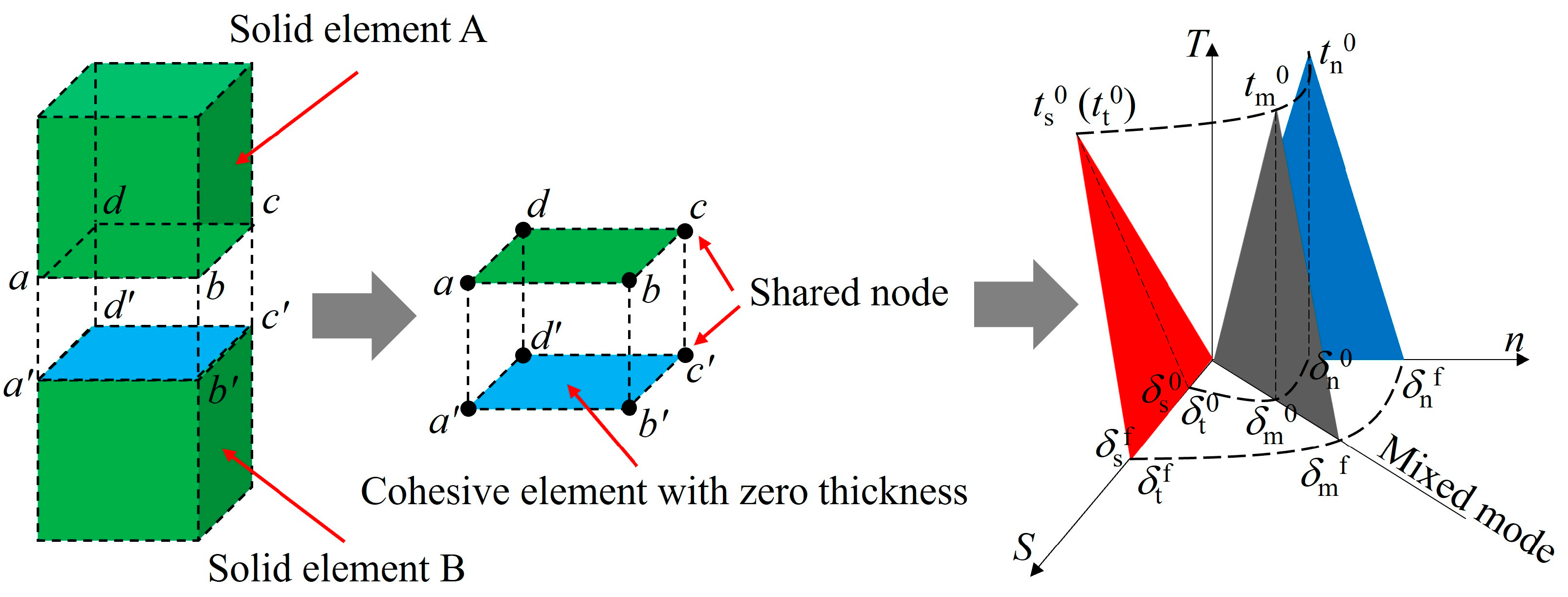
2. Construction of the Numerical Calculation Model Based on the CZM Method

2.1. Numerical Modelling Process

The numerical calculation model of layered limestone is constructed by globally inserting zero-thickness cohesive elements into a solid element using the ABAQUS finite element method, as shown in Figure 1. The advantage of the CZM method is that it can easily realize the transition from continuum to discontinuum through deformation, fracture and crushing so as to simulate the damage and failure process of rock, and it can also be directly connected with rock micromechanics parameters. Firstly, the geometric components of the layered limestone are established according to the spacing, angle and location of the bedding. Subsequently, the geometric components of the layered limestone are divided into 1 mm quadrilateral elements with green colour (CPE4R). Then, the zero-thickness cohesive elements with blue colour are inserted into the solid elements, and the cohesive elements of the bedding and the matrix are grouped, respectively, to facilitate the subsequent assigning of different mechanical parameters. The constitutive model of cohesive elements is the linear elastic constitutive model and can be described in terms of traction and separation. The basic principal of the constitutive model has been described in detail in our published studies [46,47,48,49], so it will not be introduced in this paper. In order to improve the computational efficiency of the model, the unit thickness of the numerical model is set to 1 mm. Therefore, the numerical model can be considered as a two-dimensional model. According to the actual size of the layered limestone in the laboratory test, the width and height of the numerical specimen are set to 50 mm and 100 mm, respectively, and the bedding spacing is set to 5 mm. The bedding spacing of all subsequent models are kept the same. In this paper, bedding angle (A) is defined as the angle between the bedding and the horizontal line. The bedding angles of layered limestone in the numerical simulation are set to 0°, 30°, 60° and 90°, namely A0, A30, A60 and A90. Therefore, the abbreviation A0 represents the bedding angle of layered limestone at 0°; the abbreviation A30 represents the bedding angle of layered limestone at 30°; the abbreviation A60 represents the bedding angle of layered limestone at 60°, and the abbreviation A90 represents the bedding angle of layered limestone at 90°. The test loading device is composed of two rigid pressure plates at the top and bottom. The bottom pressing plate is fixed to ensure a high degree of consistency between the simulated loading conditions and the test conditions. The load is applied via one-way displacement loading, and the loading rate of the top plate is constant at 0.15 mm/min, which is the same as the laboratory test.

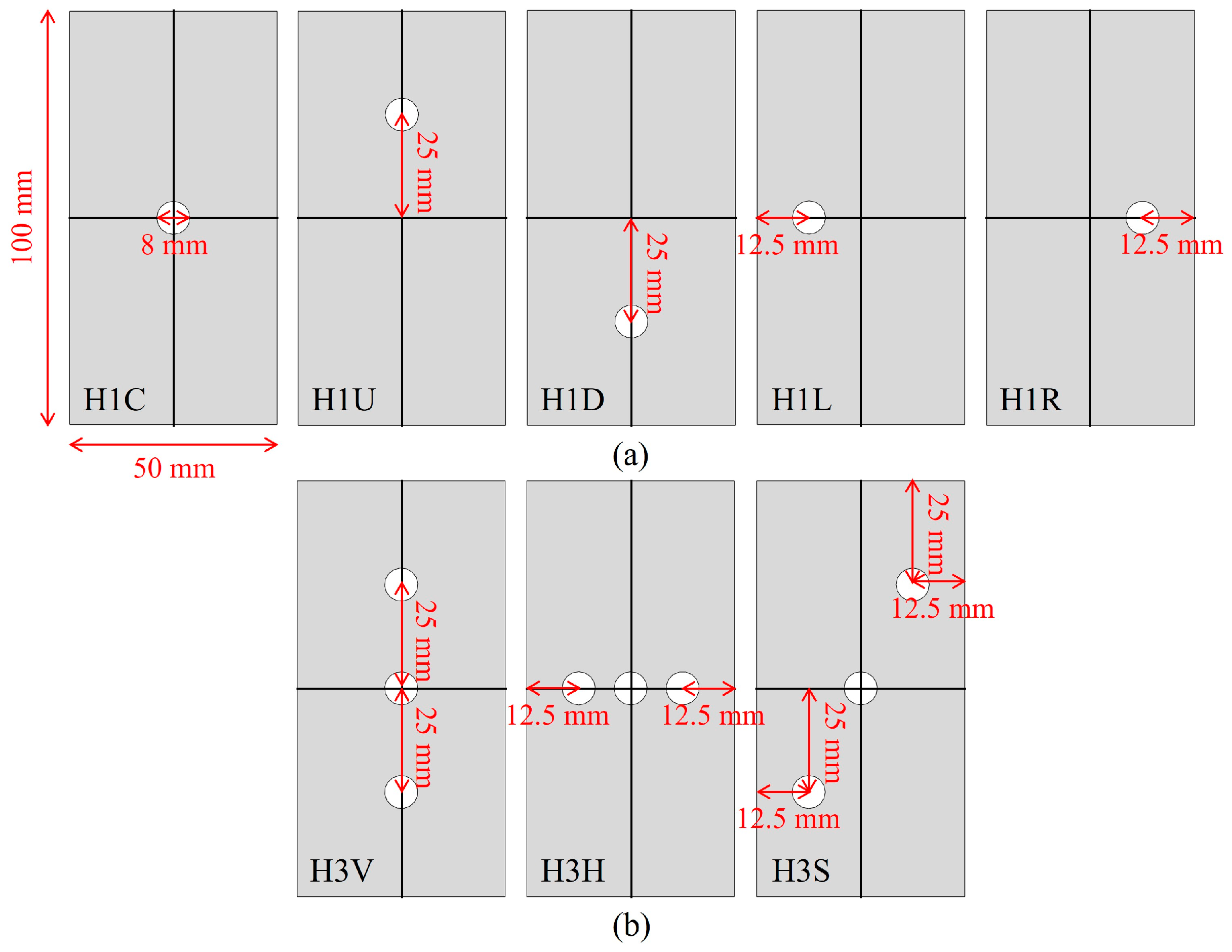
2.2. Parameter Calibration and Numerical Simulation Scheme

As the mechanical parameters used to characterize cohesive elements are usually difficult to measure through laboratory tests, it is necessary to check the microparameters of cohesive elements based on the macro mechanical properties obtained from the uniaxial compression test of layered limestone. The layered limestone blocks were taken from a tunnel of the Rongan–Congjiang Express in China. Subsequently, the blocks sampled in the tunnel field were processed into 50 × 100 cylinder specimens for uniaxial compression tests via the MTS 816 mechanical test loading system. The loading rate is set to 0.15 mm/min. The anisotropy of limestone specimens is remarkable. In this study, the stress–strain curve and the failure pattern of layered limestone are taken as the check indexes, and the parameters are repeatedly adjusted. The corresponding numerical simulation results are compared with the test results until the numerical simulation results are consistent with the test results. The mechanical parameters of the matrix are obtained from laboratory tests, as shown in Table 1. By performing the trial-and-error method, the cohesive elements’ parameters of the matrix and bedding are listed in Table 2 and Table 3, respectively.
Figure 2 and Figure 3 show the comparison of the stress–strain curves and the failure patterns of layered limestone at different bedding angles between experimental and numerical simulations. It is obvious that at different A values, the numerical stress–strain curves’ morphology of layered limestone is close to the corresponding experimental results. At different A values, the numerical peak stress (σ1p) and peak strain (ε1p) are very close to the corresponding experimental results. For the failure patterns of layered limestone, the experimental and numerical main cracks of layered limestone at A0 are mainly composed of cracks passing through the bedding; the main cracks of layered limestone at A30 are composed of cracks passing through the bedding and cracks along the bedding; and the main cracks of layered limestone at A60 and A90 mainly propagate along the bedding. From the above analysis, it can be seen that the stress–strain curve and the failure pattern of the layered limestone obtained by numerical simulations under a uniaxial compression test are in good agreement with the experimental results. It can be seen that the numerical model constructed in this paper and the microparameters in Table 1, Table 2 and Table 3 can be used to simulate the mechanical properties of the layered limestone under a uniaxial compression test.
The numerical simulation scheme in this paper is shown in Figure 4. At each bedding angle, eight layout schemes of holes are set (five layout schemes of a single hole and three layout schemes of three holes). Considering the numerical simulation scheme in this paper (i.e., the layout of holes) and the size of the whole specimen, the hole diameter was set to 8 mm in the numerical simulation. The effects of hole location and hole number on the mechanical behaviour of layered limestone at different bedding angles are studied in depth. For the single hole, the hole is located at the central, up, down, left and right of the numerical specimens, which are named as H1C, H1U, H1D, H1L and H1R, respectively. For three holes, the holes are located along the vertical central line, horizontal central line and diagonal line, which are named as H3V, H3H and H3S, respectively.

3. Numerical Calculation Results

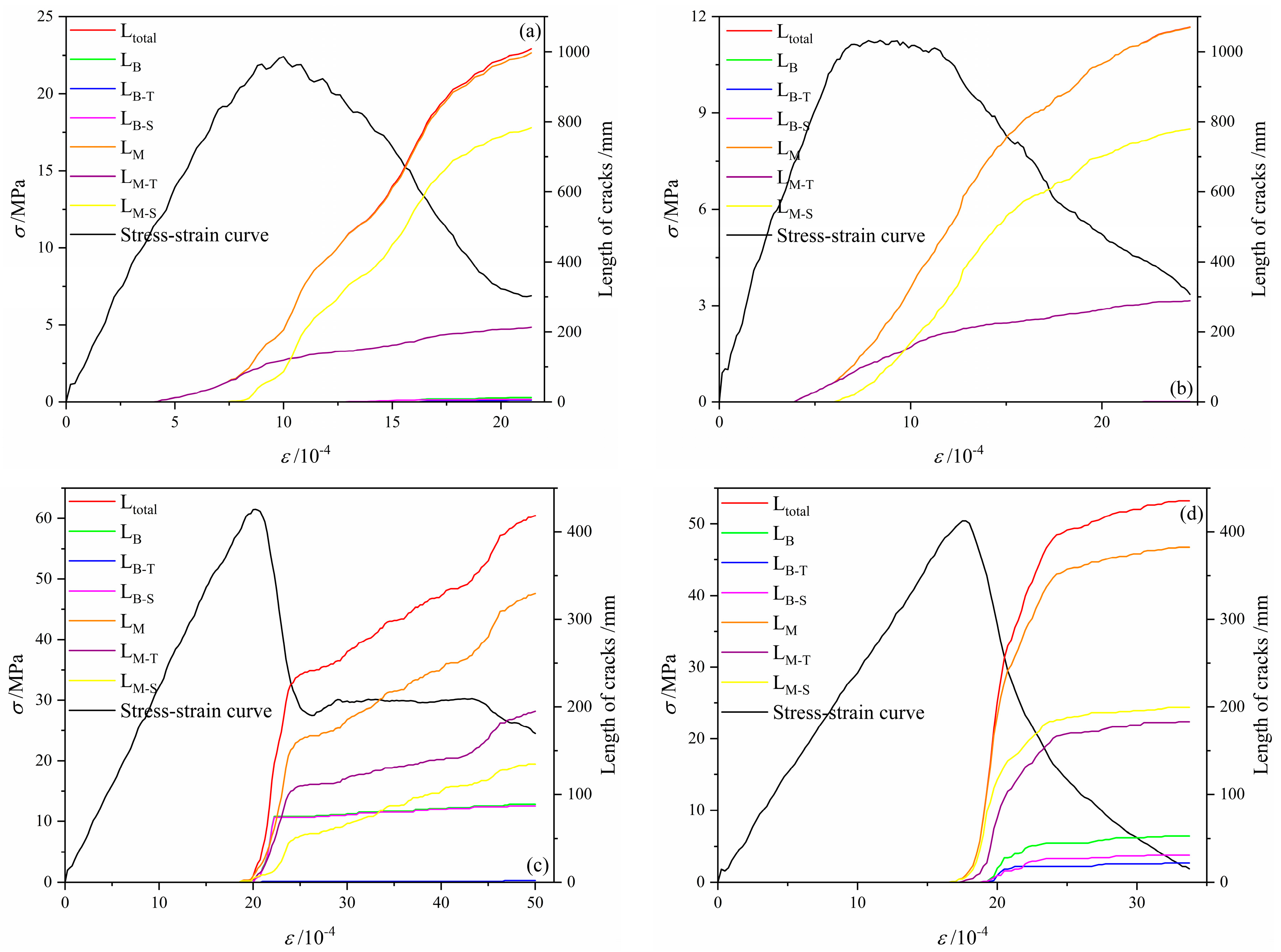
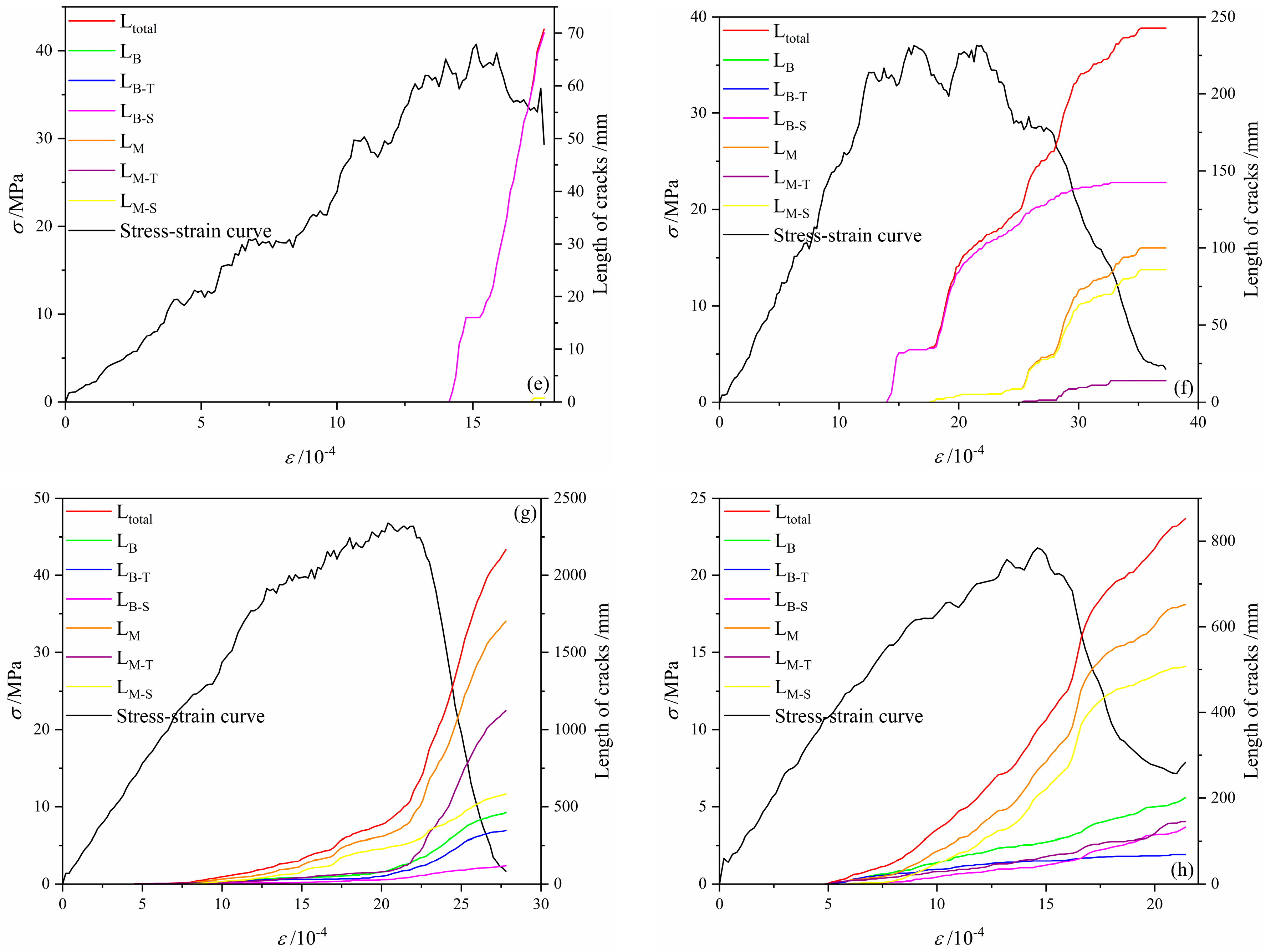
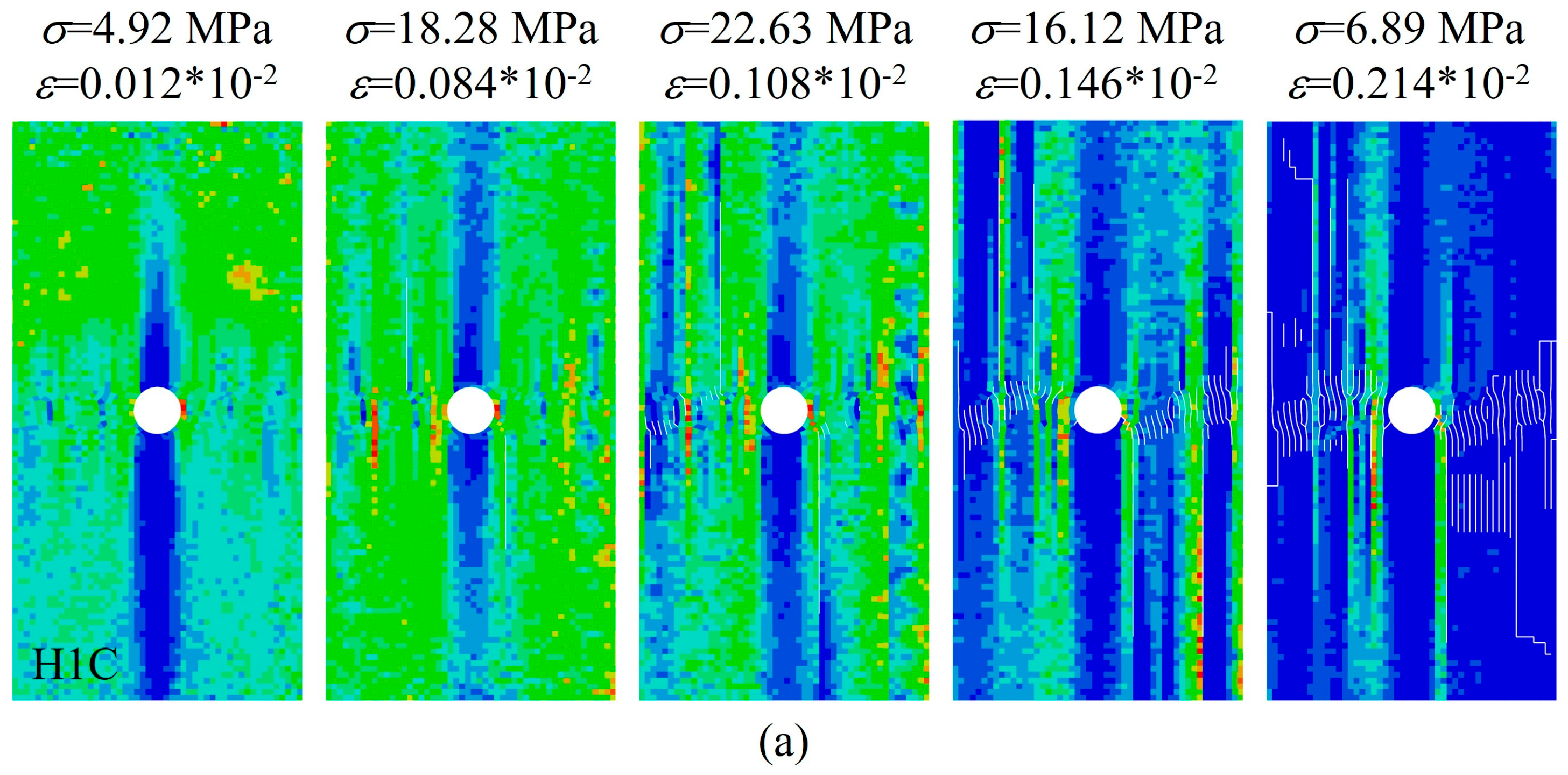
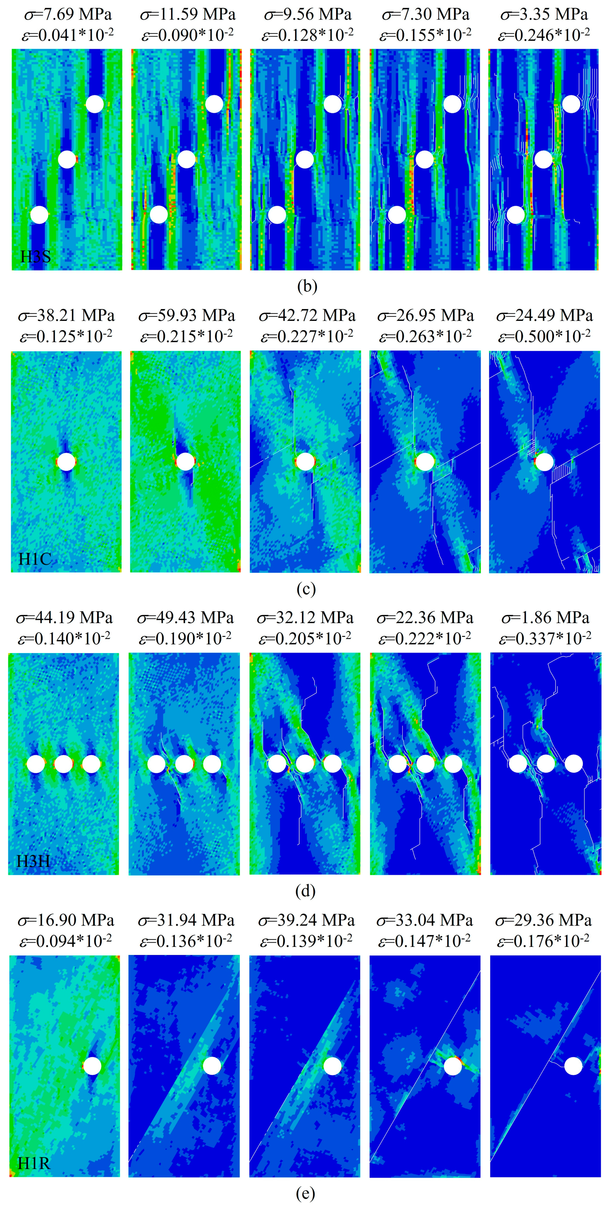
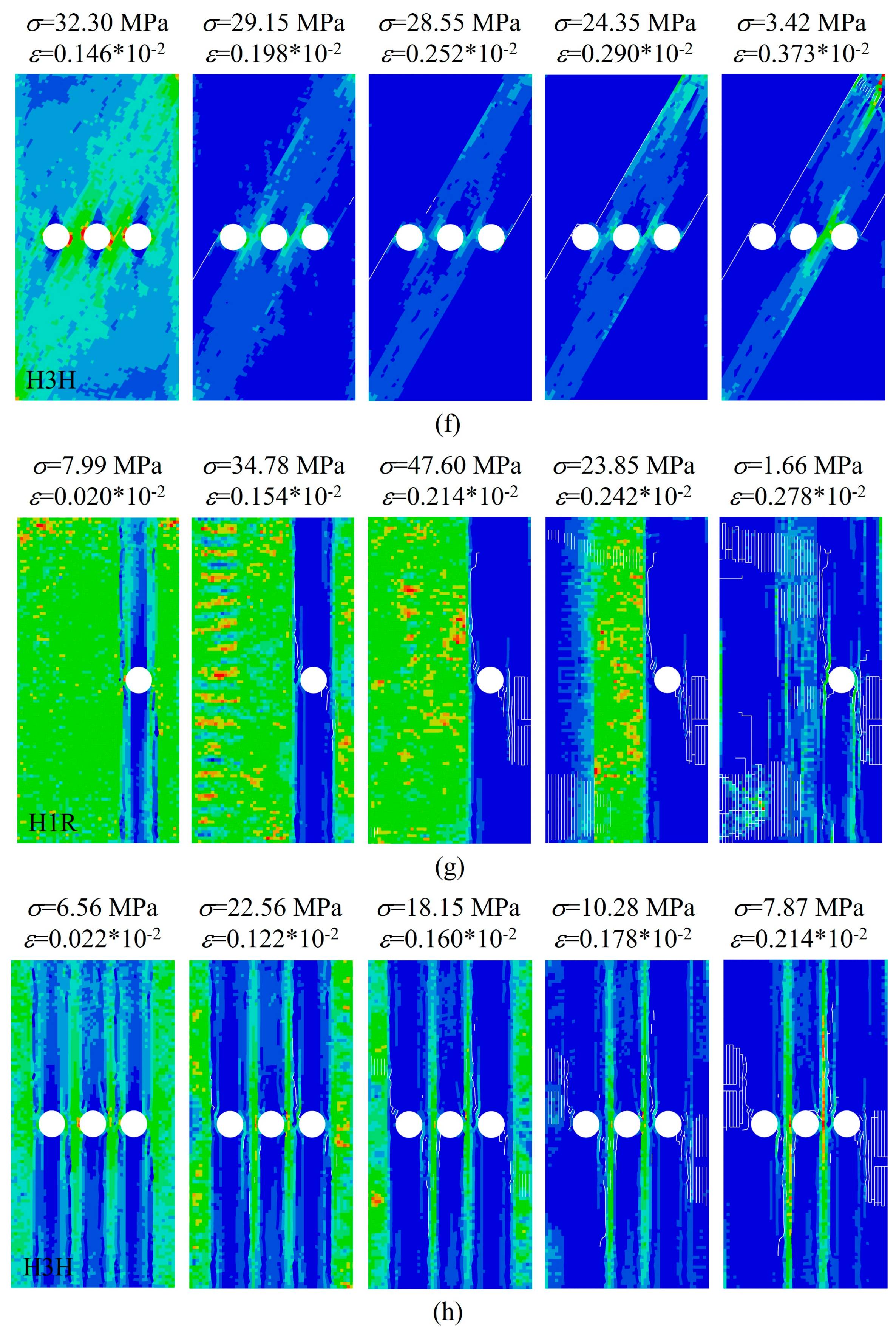
3.1. Stress and Crack Evolution Process of Layered Limestone Under Different Conditions

First, the cracks’ initiation, propagation and penetration processes of typical numerical layered limestone under external loading are analyzed in detail, as shown in Figure 5 and Figure 6. In Figure 5, Ltotal, LB, LB-T, LB-S, LM, LM-T and LM-S represent the length of total cracks, the length of cracks along the bedding, the length of tensile cracks along the bedding, the length of cracks along the matrix, the length of tensile cracks along the matrix, the length of shear cracks along the matrix, respectively. The detailed analysis is as follows:
(1) At A0 and H1C, tensile cracks along the matrix are first found around the hole (σ = 12.71 MPa and ε = 0.042 × 10⁻²) and will propagate gradually with the increasing stress value. At σ = 18.87 MPa and ε = 0.076 × 10⁻², shear cracks along the matrix are found, and LM-S will increase rapidly, as the increasing rate is faster than that of tensile cracks along the matrix. Correspondingly, cracks along the matrix can be clearly found at the left and right sides of the hole, and the length of cracks will increase constantly. With the increasing stress value, the cracks at the left and right sides of the hole will propagate to the up and bottom boundary of the numerical specimen. When the numerical specimen fails, the cracks are mainly along the matrix, the cracks’ type is mainly shear cracks, and the length of cracks along the bedding is very small.
(2) At A0 and H3S, the change in cracks during the loading process is similar with the numerical specimen at A0 and H1C. The differences are mainly reflected in the difference in the surface crack propagation of numerical specimens. At A0 and H3S, the cracks will first initiate at the holes and then propagate to the up and down of the holes. Because the hole is the weak position of the numerical specimen, the cracks can easily propagate to the holes. Therefore, the three holes are pierced first during the loading process. Then, the cracks will propagate to the up and bottom of the numerical specimen; the numerical specimen will lose its bearing capacity, and the numerical specimen will fail.
(3) At A30 and H1C, the cracks along both the bedding and the matrix are first found at about σ = 65.50 MPa and ε = 0.202 × 10⁻². With continuous loading, the length of cracks along the bedding and matrix will continuously increase. Correspondingly, the cracks along the bedding will be found near the hole, and the cracks along the matrix will first initiate at the hole and then propagate to the up and bottom of the numerical specimen. Under the bedding influence, the cracks propagating along the matrix will show a certain degree of bending. At σ = 49.11 MPa and ε = 0.222 × 10⁻², the length of cracks along the bedding and matrix both increases abruptly. Subsequently, the length of cracks along the bedding will increase very slowly, and the cracks’ type is mainly shear cracks along the bedding. On the other hand, the length of cracks along the matrix will increase constantly until the numerical specimen is pierced and loses its bearing capacity. When the numerical specimen fails, the cracks along the matrix are composed of tensile and shear cracks, and the crack ratio of tensile cracks is larger.
(4) At A30 and H3H, the cracks along both the bedding and the matrix are first found at about σ = 49.43 MPa and ε = 0.190 × 10⁻². Then, the length of cracks along the bedding and matrix first increases rapidly, and the increasing rate gradually decreases. Correspondingly, the cracks will first initiate at the left and right sides of the hole and then propagate to the up and bottom of the numerical specimen until the specimen fails. When the numerical specimen fails, the cracks mainly propagate along the matrix, and the shear crack ratio is slightly larger than that of tensile cracks.
(5) At A60 and H1R, the cracks along the bedding first initiate at the lower left part of the numerical specimen and then propagate along the bedding to the upper right part of the numerical specimen. Then, the cracks along the matrix initiate at the hole and propagate to the cracks along the bedding. When the numerical specimen fails, the cracks are mainly composed of shear cracks along the bedding.
(6) At A60 and H3H, the failed numerical specimen is mainly composed of shear cracks along the bedding. Under this condition, the numerical specimen contains three holes. The cracks first initiate at the bedding and propagate to the left hole and right hole until the specimen fails.
(7) At A90 and H1R, the cracks first initiate at the right hole and then propagate to the top and bottom of the numerical specimen. Meanwhile, many cracks will initiate at the lower left part of the numerical specimen and gradually propagate during the loading process. At σ = 1.66 MPa and ε = 0.278 × 10⁻², the numerical specimen fails and loses its bearing capacity. The failed specimen is composed of cracks both along the bedding and the matrix; the length of cracks along the matrix is larger than that of cracks along the bedding.
(8) At A90 and H3H, the cracks first initiate at the left and right of each hole and then propagate to the top and bottom of the numerical specimen. For the central hole, the cracks initiate at the left of the hole and then propagate to the bottom of the numerical specimen. During the loading process, these cracks will gradually connect with the cracks initiated at the left hole. For the central hole, other cracks initiate at the right of the hole and then propagate to the top of the numerical specimen. During the loading process, these cracks will gradually connect with the cracks initiated at the right hole. At σ = 7.87 MPa and ε = 0.214 × 10⁻², the numerical specimen fails and loses its bearing capacity. The failed specimen is composed of cracks both along the bedding and the matrix; the length of cracks along the matrix is dominant.

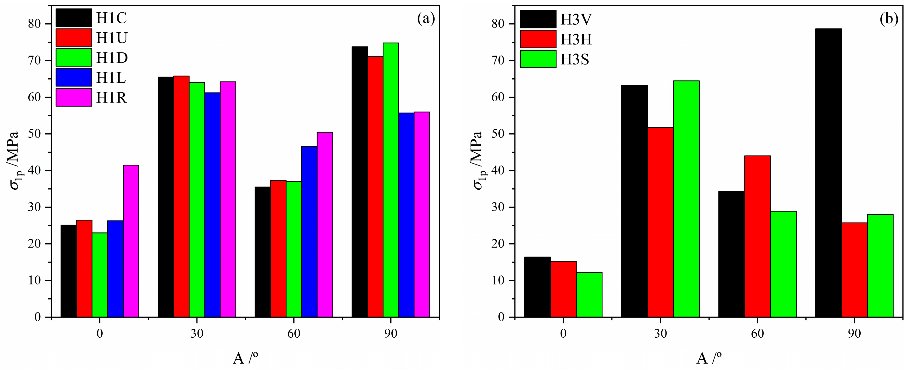
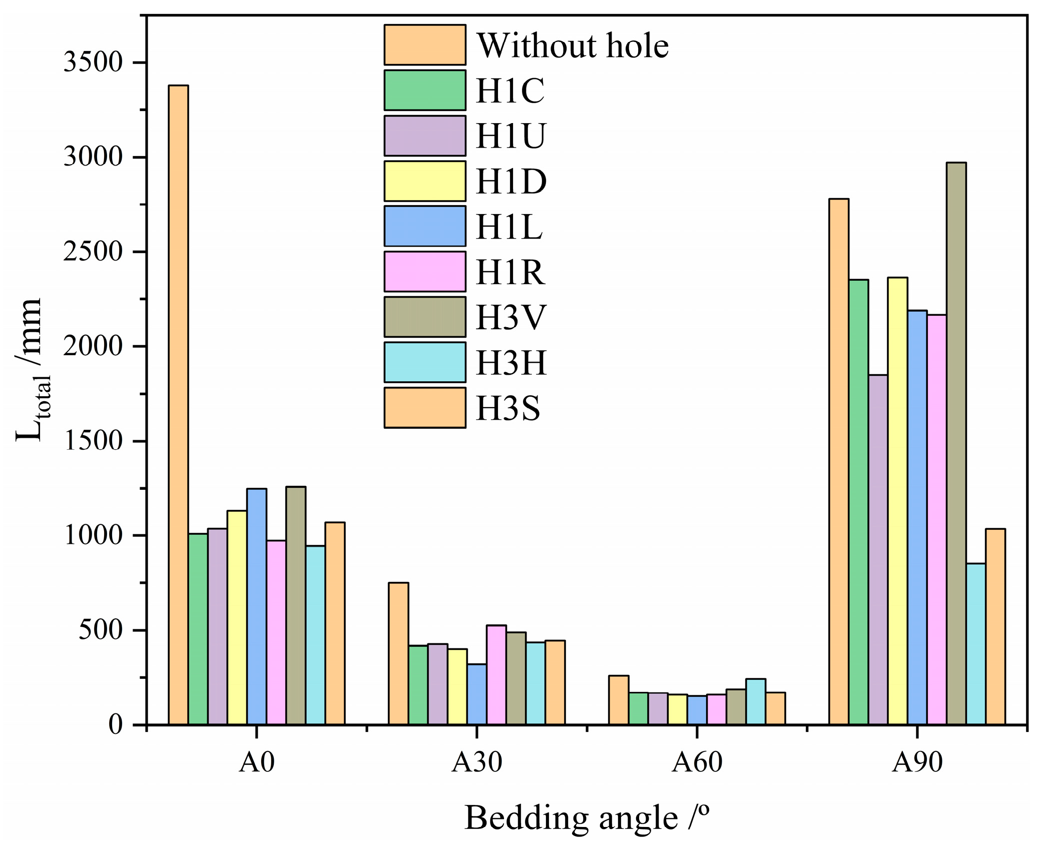
3.2. Effect of the Bedding and Hole on Peak Stress

Figure 7 shows the peak stress of numerical layered limestone under different conditions. To quantitatively characterize the effect of holes on peak stress, the decrease rate (DR) of numerical layered limestone with holes with respect to the intact layered limestone is introduced. Each DR value of numerical layered limestone with holes is shown in Figure 8. The detailed analysis is as follows:
(1) Both the number and location of holes will cause damage to the numerical layered limestone. Under different conditions, the peak stress of numerical layered limestone with holes is smaller than that of intact layered limestone. Under different conditions, the DR value at A0 is larger than 0.5, and the DR value at A30 is smaller than 0.3. This means that the hole has a stronger damage influence on numerical layered limestone at A0 and a weaker damage influence on numerical layered limestone at A30.
(2) For the single hole, the maximum σ1p of numerical layered limestone at A0, A30, A60 and A90 is obtained at HIR (σ1p = 41.51 MPa), H1U (σ1p = 65.81 MPa), HIR (σ1p = 50.45 MPa) and H1D (σ1p = 74.81 MPa), respectively. The minimum σ1p of numerical layered limestone at A0, A30, A60 and A90 is obtained at H1D (σ1p = 23.01 MPa), H1L (σ1p = 61.25 MPa), H1C (σ1p = 35.54 MPa) and H1L (σ1p = 55.75 MPa), respectively. For three holes, the maximum σ1p of numerical layered limestone at A0, A30, A60 and A90 is obtained at H3V (σ1p = 16.45 MPa), H3S (σ1p = 64.47 MPa), H3H (σ1p = 44.01 MPa) and H3V (σ1p = 78.68 MPa), respectively. The minimum σ1p of numerical layered limestone at A0, A30, A60 and A90 is obtained at H3S (σ1p = 12.27 MPa), H3H (σ1p = 51.78 MPa), H3S (σ1p = 28.89 MPa) and H3H (σ1p = 25.78 MPa), respectively. It can be found that at each bedding angle, the peak stress of layered limestone with three holes is not always smaller than that of layered limestone with a single hole. This means that there is no direct linear relationship between the number of holes and the damage degree to the numerical layered limestone specimen.

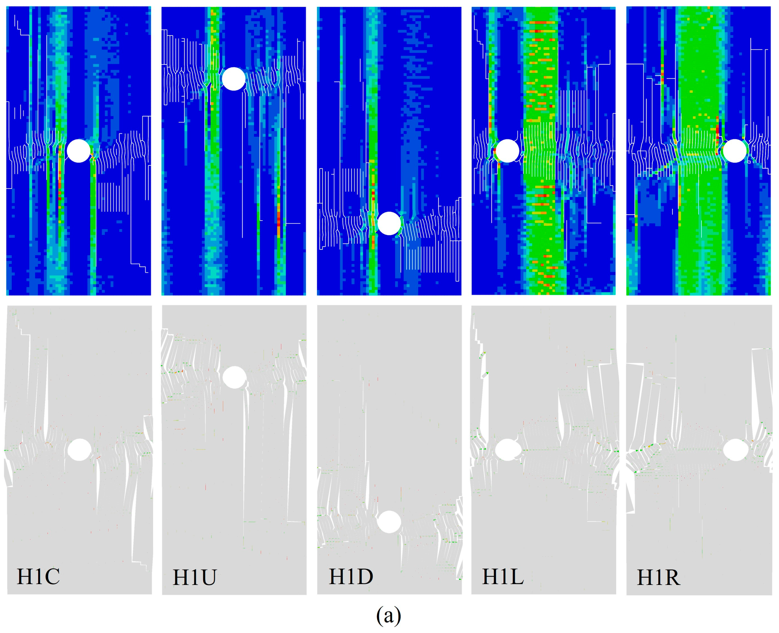
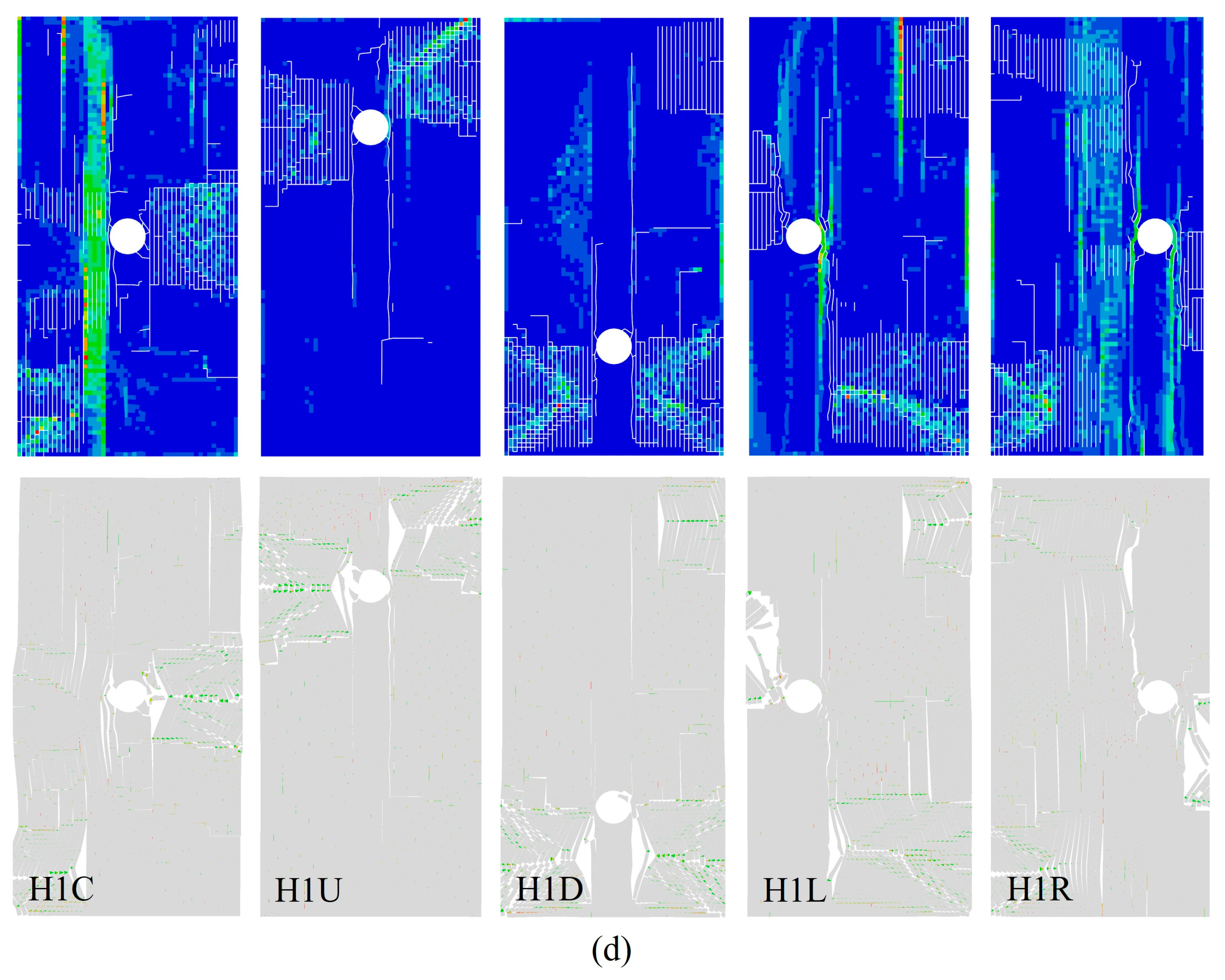
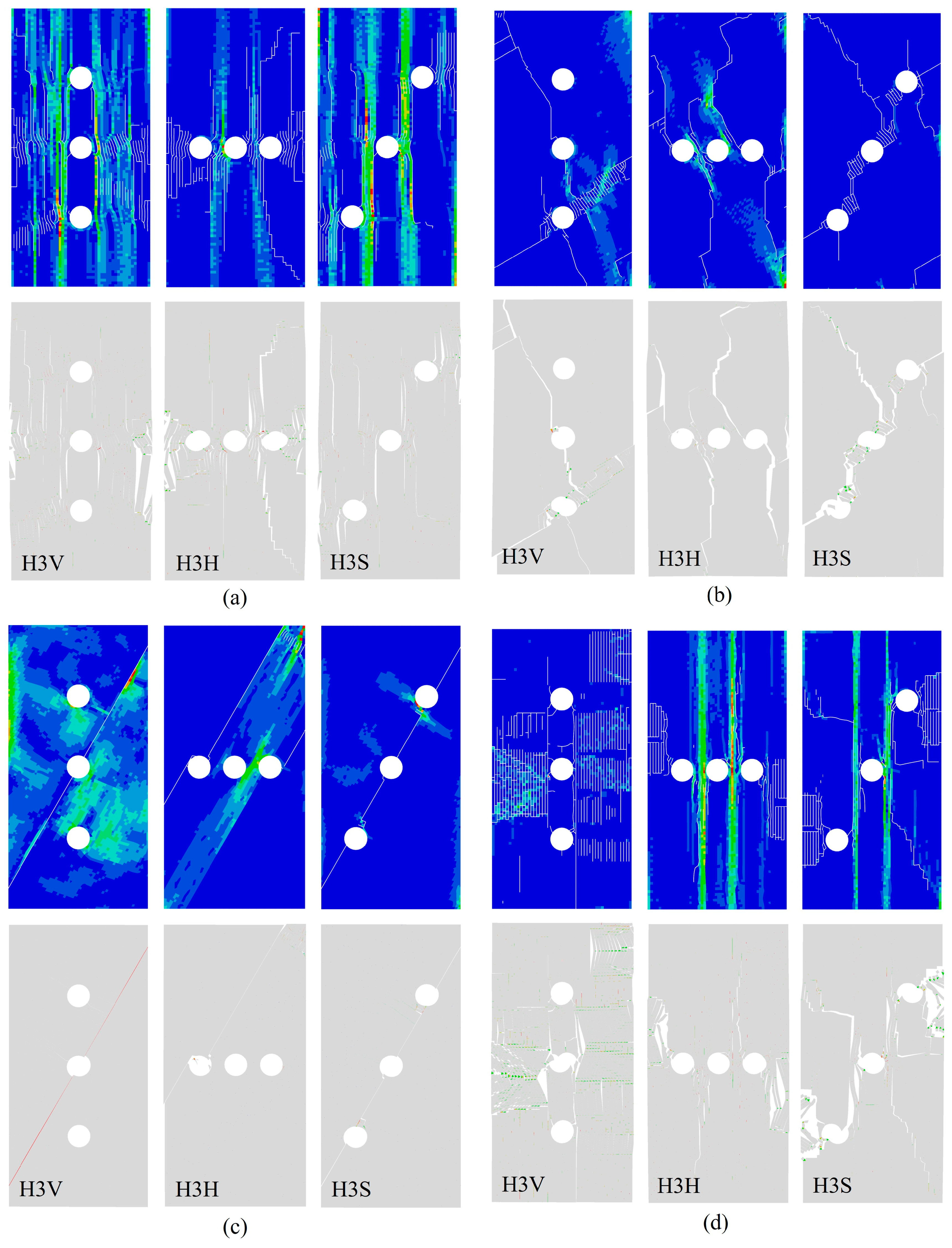
3.3. Effect of the Bedding and Hole on the Failure Pattern

The final failure patterns of the numerical layered limestone with a single hole are shown in Figure 9. The detailed analysis is as follows:
(1) At A0, the cracks mainly initiate at the hole and then propagate to the boundary of the numerical specimen. Under different conditions, the cracks mainly propagate along the matrix and along the vertical loading direction. The number of cracks is large, and the morphological characteristics of the cracks are complex.
(2) At A30, the main cracks first initiate at the hole and then propagate to the top and bottom of the numerical layered limestone at H1C, H1U, H1D, H1L and H1R. During the loading process, many cracks also initiate at the bedding and then propagate to the main cracks or holes. Different from other conditions, the cracks first initiate at the hole and then propagate to the top and bottom of the numerical layered limestone at H1R. Other cracks also initiate at the upper left and then propagate to the lower right of the numerical layered limestone specimen. When the cracks propagate for a certain distance, the cracks tend to propagate almost along the vertical loading direction and finally tend to propagate to the lower left of the numerical specimen. At the same time, the cracks initiated at the left of the hole and the upper left of the numerical specimen will gradually connect with each other during the loading process. When the numerical layered limestone specimen fails, the morphological characteristics of the cracks are complex.
(3) At A60, the failure patterns of the numerical layered limestone are simple under different conditions. The main cracks first initiate at the bedding and then propagate along the bedding. Other cracks will then initiate at the bedding and propagate to the hole at H1U, H1D, H1L and H1R. At H1C, the cracks will initiate at the bedding and propagate across the central hole.
(4) At A90, the cracks first initiate at the hole and then propagate to the boundary of the numerical layered limestone specimen under different conditions. The propagation of cracks will pass through a large number of beddings. Therefore, the morphological characteristics of cracks are complex when the numerical specimen fails.
The final failure patterns of the numerical layered limestone with three holes are shown in Figure 10. The detailed analysis is as follows:
(1) At A0, the main cracks will first initiate at each hole and then gradually connect with each other under different conditions. At the same time, the main cracks initiated at the holes will propagate to the boundary of the numerical layered limestone specimen during the loading process. When the numerical specimen fails, the morphological characteristics of the cracks are complex.
(2) At A30, the failure patterns of the numerical layered limestone are quite different under different conditions. At H3V, the main cracks will first initiate at the central and low holes and then propagate to the boundary of the numerical layered limestone specimen. For the central hole, the cracks will gradually propagate to the upper left and lower right of the numerical specimen. For the low hole, the cracks will gradually propagate to the lower left, upper right and lower right of the numerical specimen. And the cracks initiated at the central and low holes will gradually connect with each other. There are no cracks initiated at the up hole.
At H3H, the cracks mainly initiate at the left and right holes and then propagate to the top and bottom of the numerical layered limestone specimen. Under the bedding effect, the cracks show obvious bending, and the cracks are composed of cracks along the bedding and the matrix. The cracks initiated at the central hole will gradually propagate and connect with the cracks initiated at the left and right holes.
At H3S, the cracks will mainly initiate at the three holes and then propagate, and the three holes will gradually connect through the cracks’ initiation and propagation. During the loading process, other cracks will initiate at the cracks between the central and up right holes and then gradually propagate to the upper left of the numerical layered limestone specimen.
(3) At A60, the failure patterns of the numerical layered limestone are relatively simple. The cracks are mainly composed of shear cracks along the bedding and propagate across the hole. At H3V, the cracks propagate across the central hole. At H3H, the cracks propagate across the left hole. At H3S, the cracks propagate across the three holes.
(4) At A90, the cracks mainly initiate at the holes and propagate to the boundary of the numerical layered limestone specimen. During the loading process, the holes also gradually connect with each other. Under the bedding effect, the morphological characteristics of the cracks are complex, and the cracks are composed of cracks along the bedding and the matrix when the numerical specimen fails.

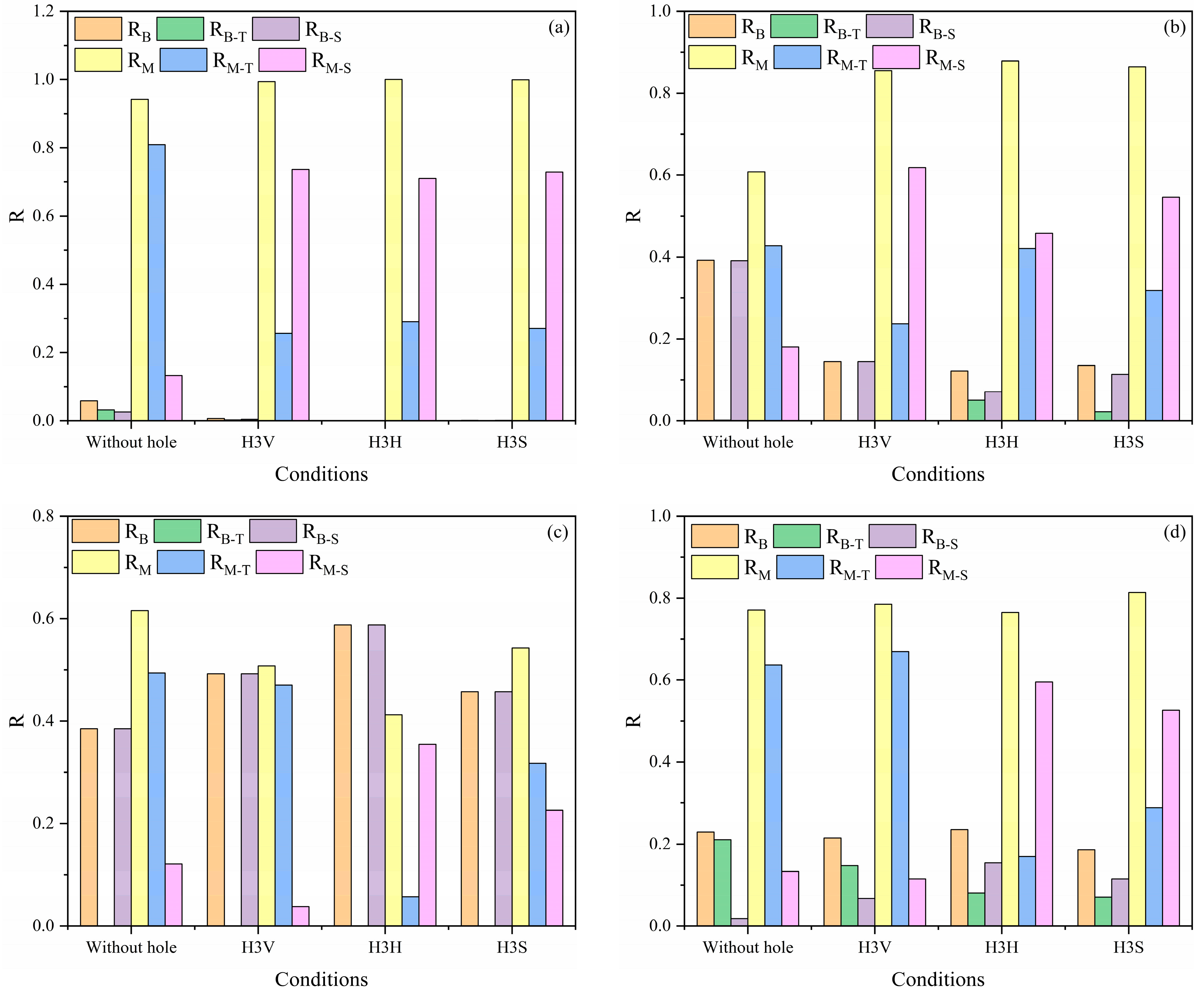
3.4. Effect of the Bedding and Hole on Microfracture Behaviour

The length of total cracks can characterize the failure characteristics of the numerical specimen to a certain extent. Figure 11 shows the length of total cracks under different conditions. It is clearly seen that both the bedding angle and the hole have strong influences on the length of total cracks when the numerical specimen fails. The detailed analysis is as follows:
(1) Under most conditions (except at A90 and H3V), the length of total cracks is smaller than that of the intact numerical layered limestone. This is mainly because for the intact numerical layered limestone, the main cracks are difficult to initiate and propagate during the loading process. A large number of secondary cracks will appear before the failure of the numerical layered limestone. Therefore, the morphological characteristics of cracks are complex, and the length of total cracks are larger when the numerical layered limestone fails. However, the hole is the weaker position for the numerical layered limestone, and the cracks are easier to initiate and propagate during the loading process. Therefore, the length of total cracks is smaller.
(2) Thus, the length of total cracks of the numerical layered limestone with holes is smaller at A60 and larger at A90. This means that the morphological characteristics of cracks are simple at A60 and complex at A90. At each bedding angle, no obvious relationship between the length of total cracks and the number of holes could be found.
(3) At A0, the maximum and minimum lengths of total cracks of the numerical layered limestone with a single hole are obtained at H1L and H1R, and the maximum and minimum lengths of total cracks of the numerical layered limestone with three holes are obtained at H3V and H3H. At A30, the maximum and minimum lengths of total cracks of the numerical layered limestone with a single hole are obtained at H1R and H1L, and the maximum and minimum lengths of total cracks of the numerical layered limestone with three holes are obtained at H3V and H3H. At A60, the maximum and minimum lengths of total cracks of the numerical layered limestone with a single hole are obtained at H1C and H1L, and the maximum and minimum lengths of total cracks of the numerical layered limestone with three holes are obtained at H3H and H3S. At A90, the maximum and minimum lengths of total cracks of the numerical layered limestone with a single hole are obtained at H1D and H1U, and the maximum and minimum lengths of total cracks of the numerical layered limestone with three holes are obtained at H3V and H3H.
The influence of holes on the ratios of different types of cracks in layered limestone is further studied (as shown in Figure 12 and Figure 13). In Figure 12 and Figure 13, RB, RB-T, RB-S, RM, RM-T and RM-S represent the ratio of cracks along the bedding, the ratio of tensile cracks along the bedding, the ratio of shear cracks along the bedding, the ratio of cracks along the matrix, the ratio of tensile cracks along the matrix and the ratio of shear cracks along the matrix, respectively. For the numerical layered limestone with a single hole, the detailed analysis is as follows:
(1) At A0, the ratio of cracks along the matrix is dominant under different conditions. The differences are that the cracks along the matrix are mainly composed of tensile cracks for intact numerical layered limestone, and the cracks along the matrix are mainly composed of shear cracks for the numerical layered limestone with a single hole. The hole has strong influences on the cracks’ type along the matrix.
(2) At A30, the cracks are mainly composed of cracks along the bedding and the matrix. Under different conditions, the ratio of cracks along the bedding is smaller than that along the matrix. The cracks along the bedding are mainly composed of shear cracks under different conditions. For the cracks along the matrix, the ratio of tensile cracks is larger at intact, H1C and H1R, and the ratio of shear cracks is larger at H1U, H1D and H1L.
(3) At A60, the main cracks of the numerical layered limestone first initiate at the bedding and then propagate along the bedding under different conditions. The cracks along the bedding are mainly composed of shear cracks. Under different conditions, the difference in crack ratios is mainly affected by secondary cracks.
(4) At A90, the cracks are mainly composed of cracks along the bedding and the matrix under different conditions. The ratio of cracks along the bedding is smaller. Among the cracks along the matrix, the ratio of tensile cracks is larger.
For the numerical layered limestone with three holes, the detailed analysis is as follows:
(1) At A0, the cracks of the numerical layered limestone are mainly composed of cracks along the matrix under different conditions. For the intact numerical layered limestone, the tensile crack ratio along the matrix is larger. For the numerical layered limestone with three holes, the shear crack ratio along the matrix is larger.
(2) At A30, the cracks of the numerical layered limestone are composed of cracks along the bedding and the matrix under different conditions. The ratio of cracks along the matrix is larger. For the cracks along the matrix, the tensile crack ratio is larger for the intact numerical layered limestone, and the shear crack ratio is larger for the numerical layered limestone with three holes. For the cracks along the bedding, the shear crack ratio is larger.
(3) At A60, the main cracks of the numerical layered limestone first initiate at the bedding and then propagate along the bedding under different conditions. The cracks along the bedding are mainly composed of shear cracks. Under different conditions, the difference in crack ratios is mainly affected by secondary cracks.
(4) At A90, the cracks are mainly composed of cracks along the bedding and the matrix under different conditions. The ratio of cracks along the bedding is smaller. Among the cracks along the matrix, the ratio of tensile cracks is larger at intact and H3V, and the ratio of shear cracks is larger at H3H and H3S.

4. Conclusions

In this paper, numerical specimens based on the CZM method are established to study the combined effects of the bedding and holes on the mechanical and fracture behaviour of layered limestone under uniaxial compression tests. Based on the numerical calculation model, the effects of bedding angle, hole location and hole number on the peak stress, failure pattern, length of total cracks and crack ratio of layered limestone are studied in depth. The research results can provide significant guidance for safety construction in layered rock mass engineering with holes. The main conclusions are as follows:
(1) The existing hole will cause damage to the numerical layered limestone at different bedding angles. Overall, the hole has a stronger damage influence on the peak stress of the numerical layered limestone at A0 and a weaker damage influence on the peak stress of the numerical layered limestone at A30. For a single hole and three holes, the hole location has different damage degrees on the peak stress of the numerical layered limestone at different bedding angles.
(2) At A60, the main cracks will propagate along the bedding under different conditions. The location and number of holes have a strong influence on the failure pattern of the numerical layered limestone at A30. At A0 and A90, the cracks first initiate at the hole and then propagate to the boundary of the numerical layered limestone specimen under different conditions, and the morphological characteristics of the cracks are complex.
(3) When the numerical specimens contain a hole, the cracks are easier to initiate and propagate. Under most conditions, the length of total cracks is smaller than that of the intact numerical specimen. Overall, the length of total cracks of the numerical layered limestone with holes is smaller and larger at A60 and A90, respectively. At different bedding angles and number of holes, the maximum and minimum lengths of cracks are obtained at different locations.
(4) Under different conditions, the main cracks mainly propagate along the matrix at A0; the main cracks propagate both along the matrix and the bedding at A30, and the ratio of cracks along the matrix is larger; the main cracks mainly propagate along the bedding at A60; the main cracks propagate both along the matrix and the bedding at A90, and the ratio of cracks along the matrix is larger.

Author Contributions

X.W.: Software, Funding acquisition, Analysis, Writing—Original draft, Writing—Review and Editing. L.G.: Investigation, Data curation. X.X.: Investigation and Writing—Original draft. F.L.: Writing—Review and Editing. All authors have read and agreed to the published version of the manuscript.

Funding

This work is financially supported by Natural Science Research Project of Anhui Educational Committee (No. 2023AH051169), Scientific Research Foundation for High-level Talents of Anhui University of Science and Technology (No. 2022yjrc11), Open Project Funding Project of Anhui Provincial Key Laboratory of Mining Construction Engineering in 2022 (No. GXZDSYS2022108).

Data Availability Statement

The datasets used and analyzed in this article are available from the corresponding author upon reasonable request.

Conflicts of Interest

Author Xiangxi Xu was employed by the Shandong Jinzhao Mining Co., Ltd. Author Fei Lin was employed by the China Coal Technology Engineering Group Huaibei Blasting Technology Research Institute Limited Company. The remaining authors declare that the research was conducted in the absence of any commercial or financial relationships that could be construed as a potential conflict of interest. The Shandong Jinzhao Mining Co., Ltd. and China Coal Technology Engineering Group Huaibei Blasting Technology Research Institute Limited Company had no role in the design of the study; in the collection, analyses, or interpretation of data; in the writing of the manuscript, or in the decision to publish the results.

References

  1. Liu, M.; Luo, X.; Bi, R.; Zhou, J.; Du, K. Impacts of bedding angle and cementation type of bedding planes on mechanical behavior of thin-layer structured bedded rocks under uniaxial compression. Geomech. Energy Envir. 2023, 35, 100473. [Google Scholar] [CrossRef]
  2. Shi, X.; Jing, J.; Yin, Q.; Zhao, Z.; Han, G.; Gao, Y. Investigation on physical and mechanical properties of bedded sandstone after high-temperature exposure. Bull. Eng. Geol. Environ. 2020, 79, 2591–2606. [Google Scholar] [CrossRef]
  3. Yang, R.; Zhou, Y.; Ma, D. Failure mechanism and acoustic emission precursors of coal samples considering bedding effect under triaxial unloading condition. Geofluids 2022, 2022, 8083443. [Google Scholar] [CrossRef]
  4. Mashhadiali, N.; Molaei, F. Theoretical and experimental investigation of a shear failure model for anisotropic rocks using direct shear test. Int. J. Rock Mech. Min. 2023, 170, 105561. [Google Scholar] [CrossRef]
  5. Yin, P.; Yang, S.; Gao, F.; Tian, W. Experiment and DEM simulation study on mechanical behaviors of shale under triaxial cyclic loading and unloading conditions. Geomech. Geophys. Geo-Energ. Geo-Resour. 2023, 9, 10. [Google Scholar] [CrossRef]
  6. Li, H.; Zhu, K.; Chen, Y.; Chen, B.; Zeng, B.; Zhang, Z. Formulation and implementation of elastoplastic constitutive model for carbonaceous slate. Bull. Eng. Geol. Environ. 2023, 82, 93. [Google Scholar] [CrossRef]
  7. Zhang, Q.; Yao, B.; Fan, X.; Li, Y.; Fantuzzi, N.; Ma, T.; Chen, Y.; Zeng, F.; Li, X.; Wang, L. A failure criterion for shale considering the anisotropy and hydration based on the shear slide failure model. Int. J. Min. Sci. Technol. 2023, 33, 447–462. [Google Scholar] [CrossRef]
  8. Liu, H.; Jing, H.; Yin, Q.; Meng, Y.; Zhu, G. Effect of bedding plane on mechanical properties, failure mode, and crack evolution characteristic of bedded rock-like specimen. Theor. Appl. Fract. Mech. 2023, 123, 103681. [Google Scholar] [CrossRef]
  9. Luo, P.; Li, D.; Ma, J.; Zhou, A.; Zhang, C. Experimental investigation on mechanical properties and deformation mechanism of soft-hard interbedded rock-like material based on digital image correlation. J. Mater. Res. Technol. 2023, 24, 1922–1938. [Google Scholar] [CrossRef]
  10. Cho, J.; Kim, H.; Jeon, S.; Min, K. Deformation and strength anisotropy of Asan gneiss, Boryeong shale, and Yeoncheon schist. Int. J. Rock Mech. Min. 2012, 50, 158–169. [Google Scholar] [CrossRef]
  11. Luo, P.; Li, D.; Zhou, A.; Ma, J.; Zhu, Q.; Jiang, J. Influence of bedding plane on the tensile properties and crack propagation of soft and hard laminated rock-like under Brazilian test. Theor. Appl. Fract. Mech. 2023, 127, 104087. [Google Scholar] [CrossRef]
  12. Lv, H.; Peng, K.; Shang, X.; Wang, Y.; Liu, Z. Experimental research on the mechanical and acoustic emission properties of layered sandstone during tensile failure. Theor. Appl. Fract. Mech. 2022, 118, 103225. [Google Scholar] [CrossRef]
  13. Cheng, J.; Wan, Z.; Zhang, Y.; Li, W.; Peng, S.; Zhang, P. Experimental study on anisotropic strength and deformation behavior of a coal measure shale under room dried and water saturated conditions. Shock Vib. 2015, 2015, 290293. [Google Scholar] [CrossRef]
  14. Meng, Y.; Jing, H.; Liu, X.; Yin, Q. Effects of initial unloading level on the mechanical, micro failure and energy evolution characteristics of stratified rock mass under triaxial unloading confining pressure. Theor. Appl. Fract. Mech. 2023, 128, 104161. [Google Scholar] [CrossRef]
  15. Song, Z.; Zhang, J.; Zhao, S.; Wu, S.; Sun, X.; Dong, X.; Zhang, Y. Brittleness of layer sandstone under triaxial loading and unloading. J. Cent. South Univ. 2023, 30, 2234–2251. [Google Scholar] [CrossRef]
  16. Yang, S.; Yin, P.; Li, B.; Yang, D. Behavior of transversely isotropic shale observed in triaxial tests and Brazilian disc tests. Int. J. Rock Mech. Min. 2020, 133, 104435. [Google Scholar] [CrossRef]
  17. Huang, D.; Li, B.; Ma, W.; Cen, D.; Song, Y. Effects of bedding planes on fracture behavior of sandstone under semi-circular bending test. Theor. Appl. Fract. Mech. 2020, 108, 102625. [Google Scholar] [CrossRef]
  18. Meng, Y.; Jing, H.; Zhou, Z.; Zhang, L.; Sun, S. Experimental investigation on the mixed-mode fracture behavior of rock-like material with bedding plane. Theor. Appl. Fract. Mech. 2022, 117, 103159. [Google Scholar] [CrossRef]
  19. Suo, Y.; Chen, Z.; Rahman, S.S.; Song, H. Experimental and numerical investigation of the effect of bedding layer orientation on fracture toughness of shale rocks. Rock Mech. Rock Eng. 2020, 53, 3625–3635. [Google Scholar] [CrossRef]
  20. Yin, Q.; Wu, S.; Meng, Y.; Wu, J.; Zhang, Q.; Jing, H. Experimental and numerical investigation on mode I fracture properties of bedded rocks. Theor. Appl. Fract. Mech. 2023, 124, 103807. [Google Scholar] [CrossRef]
  21. Kong, L.; Xie, H.; Gao, C.; Li, C. Experimental and theoretical research on the anisotropic deformation and energy evolution characteristics of shale under uniaxial cyclic loading and unloading. Int. J. Geomech. 2022, 22, 04022208. [Google Scholar] [CrossRef]
  22. Xie, Y.; Hou, M.Z.; Li, C. Anisotropic characteristics of acoustic emission and the corresponding multifractal spectrum during progressive failure of shale under cyclic loading. Int. J. Rock Mech. Min. 2023, 165, 105364. [Google Scholar] [CrossRef]
  23. Zhang, J.; Du, R.; Chen, Y.; Huang, Z. Experimental investigation of the mechanical properties and energy evolution of layered phyllite under uniaxial multilevel cyclic loading. Rock Mech. Rock Eng. 2023, 56, 4153–4168. [Google Scholar] [CrossRef]
  24. Yang, W.; Li, G.; Ranjith, P.G.; Fang, L. An Experimental Study of Mechanical Behavior of Brittle Rock-Like Specimens with Multi-Non-Persistent Joints Under Uniaxial Compression and Damage Analysis. Int. J. Damage Mech. 2019, 28, 1490–1522. [Google Scholar] [CrossRef]
  25. Huang, C.; Yang, W.; Duan, K.; Fang, L.; Wang, L.; Bo, C. Mechanical Behaviors of the Brittle Rock-Like Specimens with Multi-Non-Persistent Joints Under Uniaxial Compression. Constr. Build. Mater. 2019, 220, 426–443. [Google Scholar] [CrossRef]
  26. Yang, W.; Bo, C.; Chen, X.; Huang, C.; Li, G. Time-Dependent Behavior of Rock-Like Specimen Containing Multiple Discontinuous Joints Under Uniaxial Step-Loading Compression. Int. J. Damage Mech. 2021, 30, 872–898. [Google Scholar] [CrossRef]
  27. Wang, H.; Li, H.; Tang, L.; Li, J.; Ren, X. Fracturing Behavior of Brittle Solids Containing 3D Internal Crack of Different Depths Under Ultrasonic Fracturing. Int. J. Min. Sci. Techno. 2022, 32, 1245–1257. [Google Scholar] [CrossRef]
  28. Zhao, Z.; Shou, Y.; Zhou, X. Microscopic Cracking Behaviors of Rocks Under Uniaxial Compression with Microscopic Multiphase Heterogeneity by Deep Learning. Int. J. Min. Sci. Technol. 2023, 33, 411–422. [Google Scholar] [CrossRef]
  29. Wang, Y.; Yang, H.; Han, J.; Zhu, C. Effect of rock bridge length on fracture and damage modelling in granite containing hole and fissures under cyclic uniaxial increasing-amplitude decreasing-frequency (CUIADF) loads. Int. J. Fatigue 2022, 158, 106741. [Google Scholar] [CrossRef]
  30. Zhu, Q.; Li, D.; Han, Z.; Xiao, P.; Li, B. Failure characteristics of brittle rock containing two rectangular holes under uniaxial compression and coupled static-dynamic loads. Acta Geotech. 2022, 17, 131–152. [Google Scholar] [CrossRef]
  31. Yang, S.; Yang, Z.; Jing, H.; Xu, T. Fracture evolution mechanism of hollow sandstone under conventional triaxial compression by X-ray micro-CT observations and three-dimensional numerical simulations. Int. J. Solids Struct. 2020, 190, 156–180. [Google Scholar] [CrossRef]
  32. Zhao, R.; Tao, M.; Zhao, H.; Cao, W.; Li, X.; Wang, S. Dynamics fracture characteristics of cylindrically-bored granodiorite rocks under different hole size and initial stress state. Theor. Appl. Fract. Mech. 2020, 109, 102702. [Google Scholar] [CrossRef]
  33. Chen, S.; Xia, Z.; Feng, F.; Yin, D. Numerical study on strength and failure characteristics of rock samples with different hole defects. Bul. Eng. Geol. Environ. 2021, 80, 1523–1540. [Google Scholar] [CrossRef]
  34. Feng, F.; Chen, S.; Li, D.; Huang, W.; Peng, K.; Zang, C. Excavation unloading-induced fracturing of hard rock containing different shapes of central holes affected by unloading rates and in situ stresses. Energy Sci. Eng. 2020, 8, 4–27. [Google Scholar] [CrossRef]
  35. Tian, W.; Yang, S.; Huang, Y. Discrete element modeling on crack evolution behavior of sandstone containing two oval flaws under uniaxial compression. Arab. J. Geosci. 2020, 13, 418. [Google Scholar] [CrossRef]
  36. Wu, H.; Zhao, G.; Liang, W. Mechanical properties and fracture characteristics of pre-holed rocks subjected to uniaxial loading: A comparative analysis of five hole shapes. Theor. Appl. Fract. Mech. 2020, 105, 102433. [Google Scholar] [CrossRef]
  37. Chen, M.; Zhang, Y.; Zhang, G.; Zhou, G.; Wang, Z. Discrete element study on mechanical response and pressure relief effect of rock containing variable hole. Theor. Appl. Fract. Mech. 2023, 127, 103976. [Google Scholar] [CrossRef]
  38. Huang, Y.; Yang, S.; Tian, W. Cracking process of a granite specimen that contains multiple pre-existing holes under uniaxial compression. Fatigue Fract. Eng. Mater. Struct. 2019, 42, 1341–1356. [Google Scholar] [CrossRef]
  39. Huang, Y.; Yang, S.; Tian, W.; Wu, S. Experimental investigation on the mechanical properties of thermally damaged granite specimens containing pre-existing holes. Fatigue Fract. Eng. Mater. Struct. 2023, 46, 1443–1454. [Google Scholar] [CrossRef]
  40. Ma, W.; Chen, Y.; Yi, W.; Guo, S. Investigation on crack evolution behaviors and mechanism on rock-like specimen with two circular-holes under compression. Theor. Appl. Fract. Mech. 2022, 118, 103222. [Google Scholar] [CrossRef]
  41. Li, S.; Lin, H.; Cao, R.; Wang, Y.; Zhao, Y. Mechanical behavior of rock-like specimen containing hole-joint combined flaw under uniaxial loading: Findings from DIC and AE monitoring. J. Mater. Res. Technol. 2023, 26, 3426–3449. [Google Scholar] [CrossRef]
  42. Liu, P.; Xie, X.; Liu, Q.; Deng, P.; Huang, X.; Bo, Y. Influence of the oval hole on rock mechanical mechanism under uniaxial and biaxial compression: Insights from the combined finite-discrete element method. Eur. J. Environ. Civ. Eng. 2023, 27, 3324–3342. [Google Scholar] [CrossRef]
  43. Tan, L.; Zhou, Z.; Cai, X.; Rui, Y. Analysis of mechanical behaviour and fracture interaction of multi-hole rock mass with DIC measurement. Measurement 2022, 191, 110794. [Google Scholar] [CrossRef]
  44. Wang, M.; Lu, Z.; Zhao, Y.; Wan, W. Peak strength, coalescence and failure processes of rock-like materials containing preexisting joints and circular holes under uniaxial compression: Experimental and numerical study. Theor. Appl. Fract. Mech. 2023, 125, 103898. [Google Scholar] [CrossRef]
  45. Zhao, Z.; Jing, H.; Shi, X.; Han, G. Experimental and numerical study on mechanical and fracture behavior of rock-like specimens containing pre-existing holes flaws. Eur. J. Environ. Civ. Eng. 2022, 26, 299–319. [Google Scholar] [CrossRef]
  46. Meng, Y.; Jing, H.; Liu, X.; Yin, Q.; Wei, X. Experimental and numerical investigation on the effects of bedding plane properties on the mechanical and acoustic emission characteristics of sandy mudstone. Eng. Fract. Mech. 2021, 245, 107582. [Google Scholar] [CrossRef]
  47. Meng, Y.; Jing, H.; Liu, X.; Yin, Q.; Zhang, L.; Liu, H. Experimental and numerical investigation on the effect of bedding plane properties on fracture behaviour of sandy mudstone. Theor. Appl. Fract. Mech. 2021, 114, 102989. [Google Scholar] [CrossRef]
  48. Meng, Y.; Jing, H.; Sun, S.; Chen, M.; Huang, K. Experimental and numerical studies on the anisotropic mechanical characteristics of rock-like material with bedding planes and voids. Rock Mech. Rock Eng. 2022, 55, 7171–7189. [Google Scholar] [CrossRef]
  49. Meng, Y.; Jing, H.; Yuan, L.; Zhang, L. Numerical investigation on the effect of bedding plane properties on mode I fracture characteristics of mudstone with FEM-CZM method. Bull. Eng. Geol. Environ. 2022, 81, 3. [Google Scholar] [CrossRef]
Figure 1. Numerical modelling process based on the CZM method.
Processes 13 01223 g001
Figure 2. Comparison of stress–strain curves between experimental and numerical simulations.
Processes 13 01223 g002
Figure 3. Comparison of failure patterns between experimental and numerical simulations: (a) test results; (b) simulation results. The yellow dashed circles represent the crack at the time of sample failure.
Processes 13 01223 g003
Figure 4. Numerical simulation scheme: (a) a single hole; (b) three holes.
Processes 13 01223 g004
Figure 5. Crack length of stress–strain curves of layered limestone: (a) A0 and H1C; (b) A0 and H3S; (c) A30 and H1C; (d) A30 and H3H; (e) A60 and H1R; (f) A60 and H3H; (g) A90 and H1R; (h) A90 and H3H.
Processes 13 01223 g005aProcesses 13 01223 g005b
Figure 6. The evolution of the whole process of the crack’s initiation, propagation and penetration of layered limestone under a uniaxial compression test based on the Mises stress cloud map: (a) A0 and H1C; (b) A0 and H3S; (c) A30 and H1C; (d) A30 and H3H; (e) A60 and H1R; (f) A60 and H3H; (g) A90 and H1R; (h) A90 and H3H.
Processes 13 01223 g006aProcesses 13 01223 g006bProcesses 13 01223 g006c
Figure 7. Peak stress of layered limestone with different distribution forms of holes: (a) a single hole; (b) three holes.
Processes 13 01223 g007
Figure 8. DR of peak stress with different distribution forms of holes: (a) a single hole; (b) three holes.
Processes 13 01223 g008
Figure 9. Failure patterns of layered limestone with a single hole: (a) A0; (b) A30; (c) A60; (d) A90.
Processes 13 01223 g009aProcesses 13 01223 g009bProcesses 13 01223 g009c
Figure 10. Failure patterns of the layered limestone with three holes: (a) A0; (b) A30; (c) A60; (d) A90.
Processes 13 01223 g010
Figure 11. Length of total cracks under different conditions.
Processes 13 01223 g011
Figure 12. Crack ratios of layered limestone with a single hole: (a) A0; (b) A30; (c) A60; (d) A90.
Processes 13 01223 g012aProcesses 13 01223 g012b
Figure 13. Crack ratios of the layered limestone with three holes: (a) A0; (b) A30; (c) A60; (d) A90.
Processes 13 01223 g013
Table 1. Mechanical parameters of the rock matrix.
ParameterValue
Density, ρ/kg·m−33000
Elastic modulus, E/GPa80
Poisson’s ratio, μ0.23
Table 2. Mechanical parameters of the cohesive element in the matrix.
ParameterValue
Normal stiffness, Enn/MPa·mm−17000
Shear stiffness, Ess/MPa·mm−15000
Tensile strength, Nmax/MPa11
Shear strength, Smax/MPa15
Displacement at failure/mm0.2
Table 3. Mechanical parameters of the cohesive element in the bedding.
ParameterValue
Normal stiffness, Enn/MPa·mm−13000
Shear stiffness, Ess/MPa·mm−12000
Tensile strength, Nmax/MPa6
Shear strength, Smax/MPa12
Displacement at failure/mm0.1
Disclaimer/Publisher’s Note: The statements, opinions and data contained in all publications are solely those of the individual author(s) and contributor(s) and not of MDPI and/or the editor(s). MDPI and/or the editor(s) disclaim responsibility for any injury to people or property resulting from any ideas, methods, instructions or products referred to in the content.

