Abstract
The use of supercritical carbon dioxide (SC-CO2) coiled tubing drilling technology for developing heavy oil and other special reservoirs offers significant advantages, including non-pollution of oil layers, prevention of clay swelling, avoidance of reservoir damage, compact footprint, and enhanced oil recovery, making it a highly promising innovative drilling technology. The thermo-hydraulic coupling characteristics of SC-CO2 in helical coiled tubes are critical to the design of SC-CO2 coiled tubing drilling systems. However, existing models often neglect thermal conduction, variable thermophysical properties, and friction-compression coupling effects, leading to significant deviations in the prediction of temperature and pressure variations. Considering heat transmission and fluid dynamics, a coiled tube heat-transfer model which considers varying properties of both pressure and temperature has been developed based on an optimized convective heat-transfer coefficient. Then, the physical parameters of the carbon dioxide in the helical coiled tubing were researched. Results indicated that the temperature change of carbon dioxide in helical coiled tubing was small due to the low temperature difference between the carbon dioxide and the air as well as the existence of an air interlayer and low natural convective heat-transfer efficiency. The drop in pressure of the carbon dioxide increased with increasing coiled tubing length, and the pressure was half that of the conventional drilling fluid in the same condition due to its low viscosity. The density of carbon dioxide in the helical coiled tubing changed from 1078 kg/m3 to 1047 kg/m3 with increasing coiled tubing length under the conditions stated herein, and the carbon dioxide remained liquid throughout the whole process.
1. Introduction
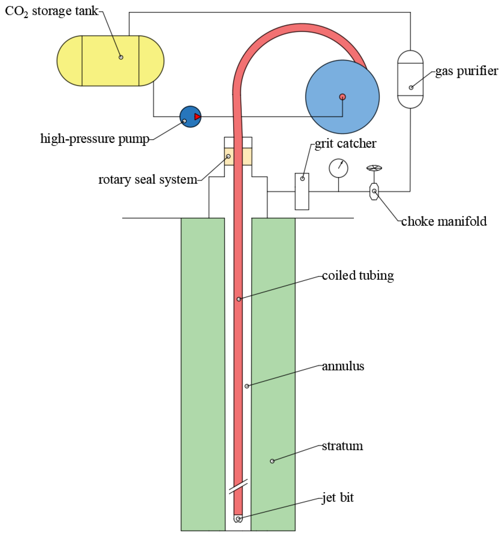
The efficient development of special hydrocarbon reservoirs, such as heavy oil reservoirs, is of significant importance in meeting global petroleum demand. However, the use of conventional drilling methods for developing these special reservoirs often leads to severe formation contamination, reduced recovery rates, and high costs. Supercritical carbon dioxide (SC-CO2) can dissolve into heavy oil, causing it to expand in volume and reduce in viscosity, thereby effectively enhancing the development efficiency of heavy oil reservoirs. Coiled tubing drilling technology, which emerged rapidly in the 1990s, has been successfully applied in various operations including re-drilling old wells, deepening wells, and small-diameter well projects. This technology offers several advantages, such as requiring less site space, shorter tripping times, and lower operational costs. The combination of carbon dioxide and coiled tubing drilling technology can greatly improve drilling efficiency and reservoir protection [1], making this a new drilling technology with great application prospects. Figure 1 shows the process of coiled tubing drilling using supercritical carbon dioxide as a drilling fluid.

Figure 1.
Supercritical carbon dioxide coiled tubing drilling.
The accurate calculation of flow pressure and temperature loss in coiled tubing is of great significance for equipment selection and bottom-hole pressure prediction for petroleum drilling. Compared with straight coiled tubing systems [2,3,4,5], horizontal tubes [6,7], and micro-tubes [8,9,10,11], studies on the flow of fluids in helical coiled tubing systems are much fewer, and this subject cannot be ignored due to the existence of secondary flow and its remarkable effect on friction loss in fluids. Thomson [12] studied the bend pipe flow characteristics and described the formation mechanism of secondary flow. Dean [13] proved the existence of secondary reflux theoretically for the first time. Because of the existence of secondary reflux, the critical Reynolds number of flow transition from layer to turbulence flow in helically coiled tubing is obviously higher than that in a straight pipe [14,15,16]. The fluid flow in the mainstream direction, along with the direction of the cross section of the vertical mainstream direction, makes the flow friction resistance of the helically coiled tubing much higher than that of the straight pipe. White [17] carried out flow tests in bend pipes, and the results showed that the flow resistance increased with increasing pipe curvature, and the secondary flow appeared if the pipe was long enough even where the pipe curvature was lower. Zhou [18] analyzed the laminar and turbulent flows of Newtonian and non-Newtonian fluids in helical coiled tubing according to boundary layer theory and obtained the empirical formulas for calculating frictional losses, which were applicable to both laminar and turbulent flows. Moawed [19] studied forced convection heat transfer in helically coiled tubing under constant heat flow, and the results showed that the diameter and pitch of the coiled tubing had great influence on the heat-transfer coefficient. More research has been conducted on turbulent flow and heat transfer in helically coiled tubing than on laminar flow. The correlations of White [17], Ito [20], and Srinivasan [21] are widely used. Over the years, more and more scholars have studied the flow and heat transfer in helically coiled tubing with different fluids, flow states, and structure parameters [22,23,24,25,26,27,28,29]. However, few studies have focused on the flow and temperature and pressure loss of carbon dioxide in the helical coiled tubing system.
Herein, considering heat transmission and fluid dynamics, a coiled tube heat-transfer model that takes into account varying properties of both pressure and temperature has been developed based on an optimized convective heat-transfer coefficient. Then, the physical parameters of the carbon dioxide in the helical coiled tubing were researched. This study provides parameters for the calculation of straight coiled tubing systems at the wellhead and scientific knowledge for the selection of working parameters for coiled tubing drilling.
2. Modeling
2.1. Heat Transfer in the Helical Coiled Tube
Carbon dioxide is pumped into the helical coiled tube in a cryogenic liquid state, and then it flows into the straight tube in the borehole after a heat exchange with the outside environment. In the helical coiled tube section, there is a multipath heat–transfer process of solid–solid coupling and solid-gas coupling between pipes, which presents great difficulties for calculation. The contact between the helical coiled tubes is linear, and the heat conductivity of the surrounding air is low; in addition, the heat transfer between the internal helical coiled tubes has no influence on the total cooling loss of the helical coiled tubes as a whole. Thus, the heat transfer between the internal helical coiled tubes can be neglected, and we only need to consider the heat conduction between the helical coiled tubes and the coiling block and the convective heat transfer between the external wall of the helical coiled tube with the air [30], as shown in Figure 1, assuming the helical segments are tightly arranged, which means the spacing between the tubes is equal to the outer diameter of the tube. Then, the winding number of each layer of coiled tube is given by the following formula:
where N is the winding number of each layer of coiled tube; is the width of the coiling block axis, m; and and are the external and internal diameters of the helical coiled tube, m.
If each layer is wrapped, the length of the nth layer of coiled tube equals
where is the length of the nth layer of coiled tube, m; is the external diameter of the coiling block axis, m; and n is the layer number of coiled tube wound around the coiling block.
The helical coiled tubes can be divided into three parts according to heat-transfer modes. The first part includes the first layer of tube clinging to the coiling block. Its main means of heat transfer with the environment include the convective heat transfer of the internal wall of the coiled tube, the heat conduction of the coiled tube wall, the heat conduction of the air interlayer, and the heat conduction of the coiling block wall. The second part includes the second layer of tube from the coiling block and the (n − 2)th tube from the outside of the coiling block, which is not exposed to the air. Because its heat transfer with its surroundings has no influence on the total cooling loss of the helical coiled tubes as a whole, it can be regarded as having no heat exchange with the environment. The third part includes the nth layer of tube and the (n − 1)th layer of tube exposed to the air (Figure 2).
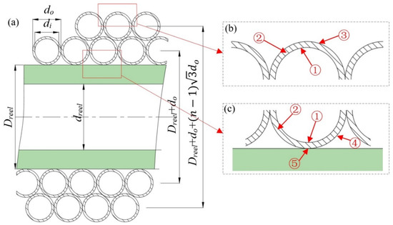
Figure 2.
Schematic cutaway view and heat-transfer pattern of helical coiled tube (a–c). ① convective heat transfer of internal wall; ② heat conduction of the coiled tube wall; ③ air natural convective heat transfer; ④heat conduction of air interlayer; ⑤ heat conduction of the coiling block wall.
2.1.1. Heat Transfer of the First Layer of Helical Coiled Tube
Assuming the helical coiled tubes are arranged very closely to each other, take the coiled tube segment with a length of dl for analysis and ignore the internal heat transfer. For the first layer of helical coiled tube wound around the coiling block, the means of heat transfer between segment dl and the environment include the convective heat transfer of the internal wall of the coiled tube, the heat conduction of the coiled tube wall, the heat conduction of the air interlayer, and the heat conduction of the coiling block wall. The energy equation can be expressed in the following differential form:
where c is the specific heat capacity, J/(); m is the mass flow rate, kg/s; T is the carbon dioxide temperature, K; K is the resultant heat-transfer coefficient, ; A is the heat-transfer area, m2; T0 is the ambient temperature, K; T1 is the initial temperature of carbon dioxide pumped into the coiled tube, i.e., , K; Rhi is the convective heat-transfer resistance of the internal wall of the helical coiled tube; Rt, Rg, and RT are the thermal-conduction resistance of the helical coiled tube, air interlayer, and coiling block axis.
Rhi (i.e., the convective heat-transfer resistance of the helical coiled tube wall) is determined by the convective heat-transfer coefficient between the carbon dioxide and the coiled tube:
where hi is the convective heat-transfer coefficient of the helical coiled tube, ; Ati is the internal area of helical coiled tube with a length of dL, m2. The heat-transfer efficiency of the helical coiled tube is higher than that of the straight tube because of the influence of secondary flow, which means its convective heat-transfer coefficient hi is different from that of the straight tube. As the flow of carbon dioxide in a helical coiled tube corresponds to a high Reynolds number flow, Rogers and Mayhew’s formula [26] was chosen to calculate hi.
Rt (i.e., the thermal-conduction resistance of the helical coiled tube with a length of dL) can be derived by the differential equation of heat conductions:
where r is the radial coordinate of the helical coiled tube, m; Tw1 and Tw2 are the temperatures of the internal and external surfaces of the helical coiled tube, K; and is the internal diameter of the helical coiled tube, m.
The temperature change rate along the radial direction can be calculated using the following formula:
The heat conductivity rate can be obtained according to Fourier’s law:
where φ is the heat conductivity rate, W; and λt is the heat conductivity of the helical coiled tube, .
The thermal-conduction resistance of the helical coiled tube with a length of dl can be expressed as:
The contact between the first layer of helical coiled tube and the coiling block axis is a line, which means the contact area ideally equals zero. There is an irregular air interlayer between them. As the size of the air interlayer is small, the natural convection is suppressed, and only the heat conductivity of the air is considered. Thus, the thermal-conduction resistance of the irregular air interlayer Rg can be expressed as:
where δ is the thickness of the air layer, m; λg is the heat conductivity of air, ; and do is the external diameter of the helical coiled tube, m.
The thermal-conduction resistance of the coiling block axis RT can be expressed as:
where λT is the heat conductivity of the coiling block axis, ; and R1 and R2 are the internal and external radii of the coiling block axis, m.
From the above, the resultant heat-transfer coefficient can be expressed as:
2.1.2. Heat Transfer of the nth Layer of Helical Coiled Tube
For the nth layer of helical coiled tube and the (n − 1)th tube exposed to the air wound around the coiling block axis, the resultant heat-transfer coefficient can be expressed as:
where h is the natural convection heat-transfer coefficient, ; and Ato is the external area of the helical coiled tube with a length of dL, m2.
The natural convection heat-transfer coefficient h can be calculated using the following formula:
where c is the specific heat capacity, ; Pr is the Prandtl number, which characterizes the relative dominance of momentum transfer to heat transfer in a fluid and is defined as the ratio of momentum diffusivity (kinematic viscosity) to thermal diffusivity; Gr is the Grashof number, which quantifies the dominance of buoyancy-driven flow (natural convection) over viscous resistance and is defined as the ratio of buoyancy forces to viscous forces in natural convection; λm is the heat conductivity of the flat wall at the average temperature, ; dm is the diameter of the equivalent transverse cylinder, for the penultimate layer from the outside, for the outermost layer, m; n is the number of layers; and c and i are coefficients which depend on flow condition, c = 0.48, i = 0.25 for laminar flow, and c = 0.10, i = 1/3 for turbulent flow.
2.2. Pressure Drop in the Helical Coiled Tube
The circulating pressure loss in the coiled tubing can be calculated using the Darcy–Weisbach equation:
where P is the hydrodynamic pressure, Pa; fCT is the frictional coefficient of the helical coiled tube; ρ is the fluid density, kg/m3; and v is the average flow velocity, m/s.
As the viscosity of carbon dioxide is low, turbulence is easily achieved. Moreover, in the case of flow through coiled tubing on the reel, the presence of a secondary flow (commonly referred to as Dean vortices) perpendicular to the main flow generates high flow resistance and makes the characterization somewhat complicated. In this paper we chose the Sas-Jaworsky and Reed correlation [31] to calculate the frictional coefficient of the helical coiled tube:
where fST is the frictional coefficient of the straight tube.
2.3. Solution Algorithm
The helical coiled tubing is divided into n segments, and each segment has the same length τ. Thus, there are n + 1 nodes. The explicit Runge–Kutta fourth-order formula is adopted to calculate heat transfer, and the temperature and pressure values of node n are used to calculate these values of node n + 1. Loop through until all the node values are obtained. As the properties of carbon dioxide (including density, viscosity, heat conductivity, and so on), flow velocity, and heat-transfer coefficient change with temperature and pressure, the parameters of nodes must be updated. The density and heat capacity of carbon dioxide were calculated using the Span–Wagner model [32], and the heat conductivity and viscosity of carbon dioxide were calculated using the the Vesovic model [33] and the Fenghour model [34], respectively.
where fCT is the frictional coefficient of the helical coiled tubing.
3. Results and Discussion
Based on the model above, an example is given to display the relationships between temperature, pressure, and density along the coiled tubing with lengths of coiled tubing under three conditions (the total length of helical coiled tubing equal to 848 m, 1448 m, and 2048 m, respectively). The inner and outer diameters of the helical coiled tubing are 43 mm and 51 mm, respectively. The outer diameter and width of the coiling block are 2032 mm and 1752.6 mm, respectively. The helical coiled tubing lengths of each layer are shown in Table 1. According to Table 1, the last layer is not filled to the brim when the length of coiled tubing is equal to 848 m or 1448 m. The curvature ratio of each layer decreases with an increase in the equivalent diameter of the coiling block. The initial temperature of the carbon dioxide equals 253.15 K and the environmental temperature equals 293.15 K. The mass flow rate of carbon dioxide is 3.78 L/s (i.e., 60 gpm), and the initial pump pressure equals 13 MPa. The helical coiled tubing is divided into segments with lengths of 2 m; then, the temperature, pressure, and density of all nodes can be obtained through iterative computations.

Table 1.
Length and curvature ratio of each layer of coiled tube.
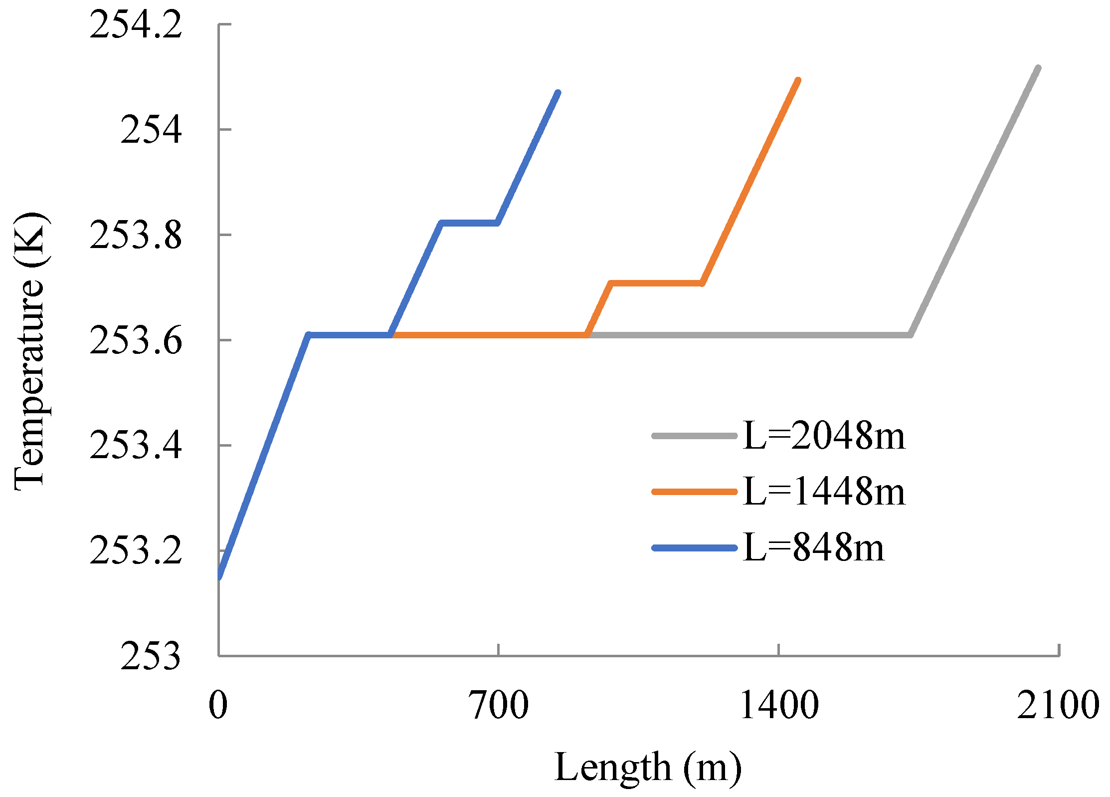
Figure 3 shows the temperature change along the coiled tubing. According to Figure 3, the temperature increases as the helical coiled tubing it flows through increases. There are two horizontal segments where the length of helical coiled tubing is equal to 848 m or 1448 m, which is due to the assumption in the model that the second part (which includes the second layer of tube from the coiling block and the (n − 2)th tube from the outside of the coiling block) does not experience heat exchange with its environment. Meanwhile, there is a rising segment between the two horizontal segments; this is because the coiled tubing winds back in the opposite direction after the first layer, meaning the carbon dioxide inside the penultimate layer from the outside flows through the segment exposed to air first, and then through the segment enclosed by the last layer, and finally through the last layer, which is completely exposed to air. Unlike the previous two cases, there is only one horizontal segment where the length of helical coiled tubing equals 2048 m, which is due to only the last layer of helical coiled tubing being exposed to the air. As a whole, the temperature at the exit increases gradually with the increase in coiled tubing length, and the temperature change is no more than 1 K, which is mainly due to the low temperature difference between the carbon dioxide and the air and the existence of an air interlayer and a low natural convective heat-transfer efficiency.
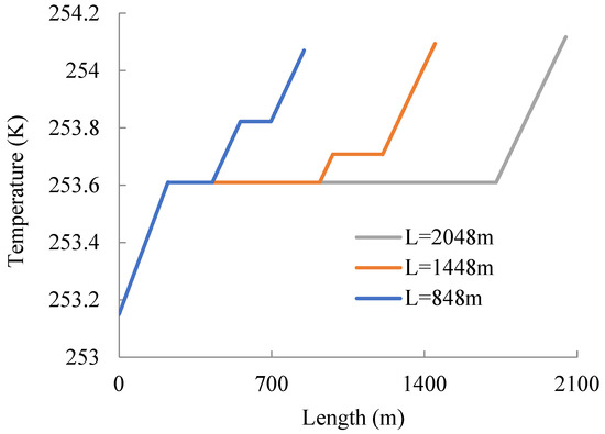
Figure 3.
Temperature–length plot of helical coiled tubing.
Figure 4 shows the pressure change along the coiled tubing. According to Figure 4, the pressure losses of 848 m, 1448 m, and 2048 m helical coiled tubes are 1.76 MPa, 3.0MPa, and 4.3 MPa, respectively. It is obvious that flow pressure loss increases with increasing coiled tube length. An experimental study on water and other power-law fluids [35] shows that the water flow pressure loss of a coiled tube with a length of 78 ft (23.7m), an inner diameter of 51 mm, and a flow rate of 3.78 L/s equals 0.0259 MPa. It can be seen that the pressure loss is half that of conventional drilling fluid in the same pipe due to the low viscosity of carbon dioxide.
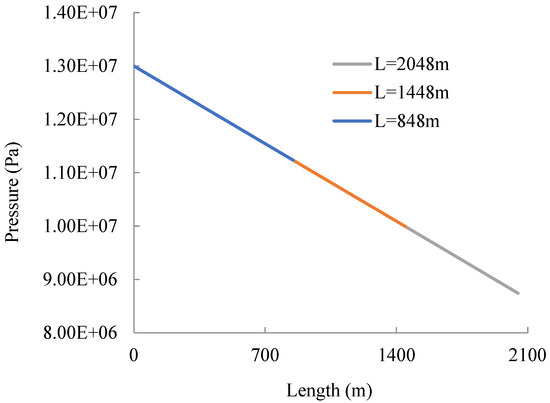
Figure 4.
Pressure–length plot of helical coiled tubing.
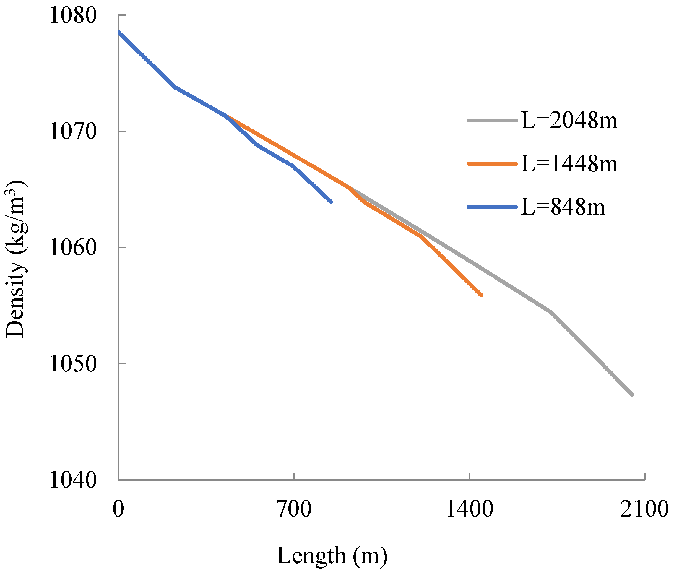
Figure 5 shows the density change along the coiled tube. According to Figure 5, the density of carbon dioxide as it flows through the helical coiled tubing changes from 1078 kg/m3 to 1047 kg/m3 with increasing coiled tube length. The carbon dioxide remains liquid throughout this process. Then, the density of the carbon dioxide changes because the pressure decreases and the temperature increases with the tube extension.

Figure 5.
Density–length plot of helical coiled tube.
4. Sensitivity Analysis on Uncertain Parameters
4.1. Thermal Conductivity Coefficient K
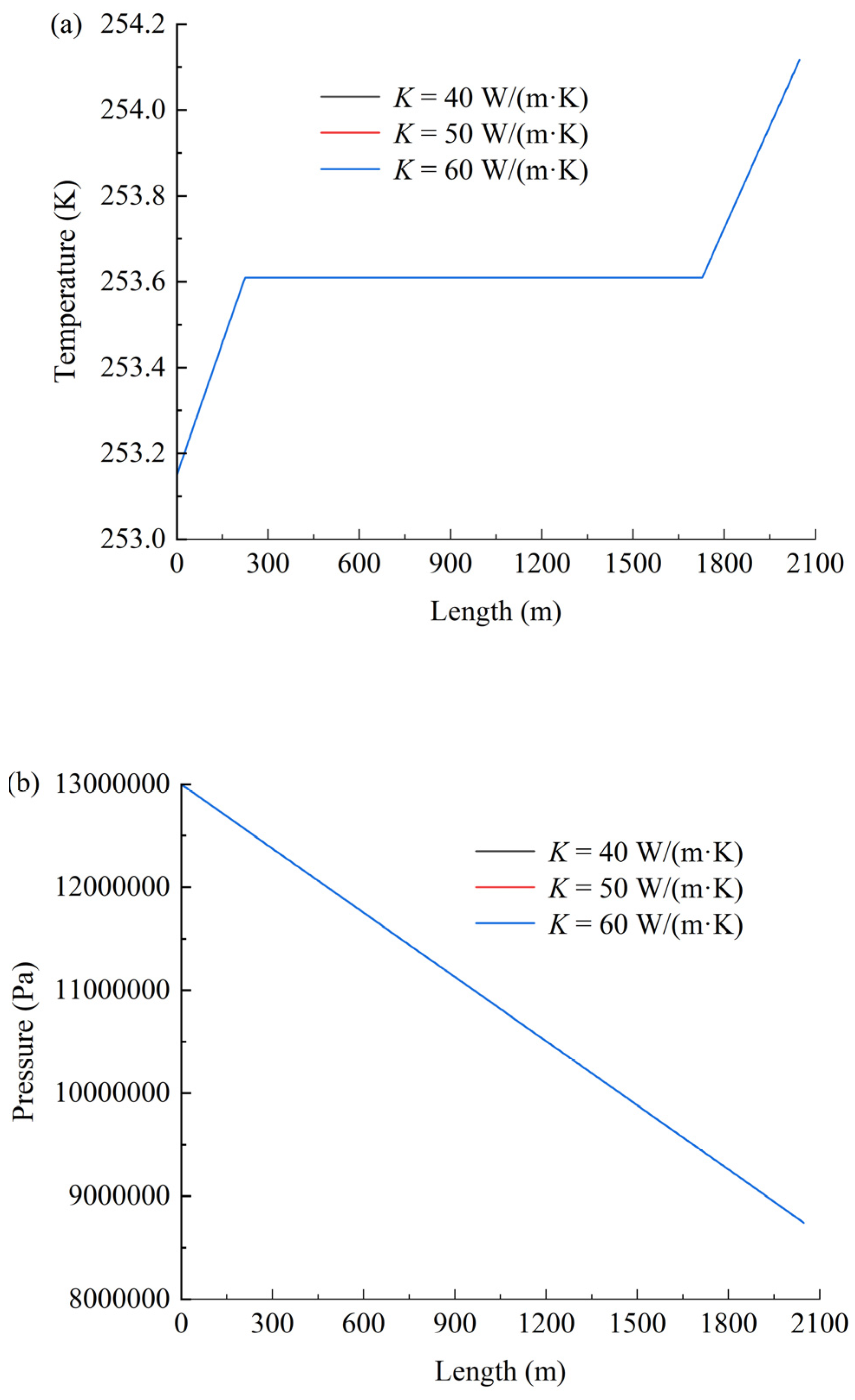
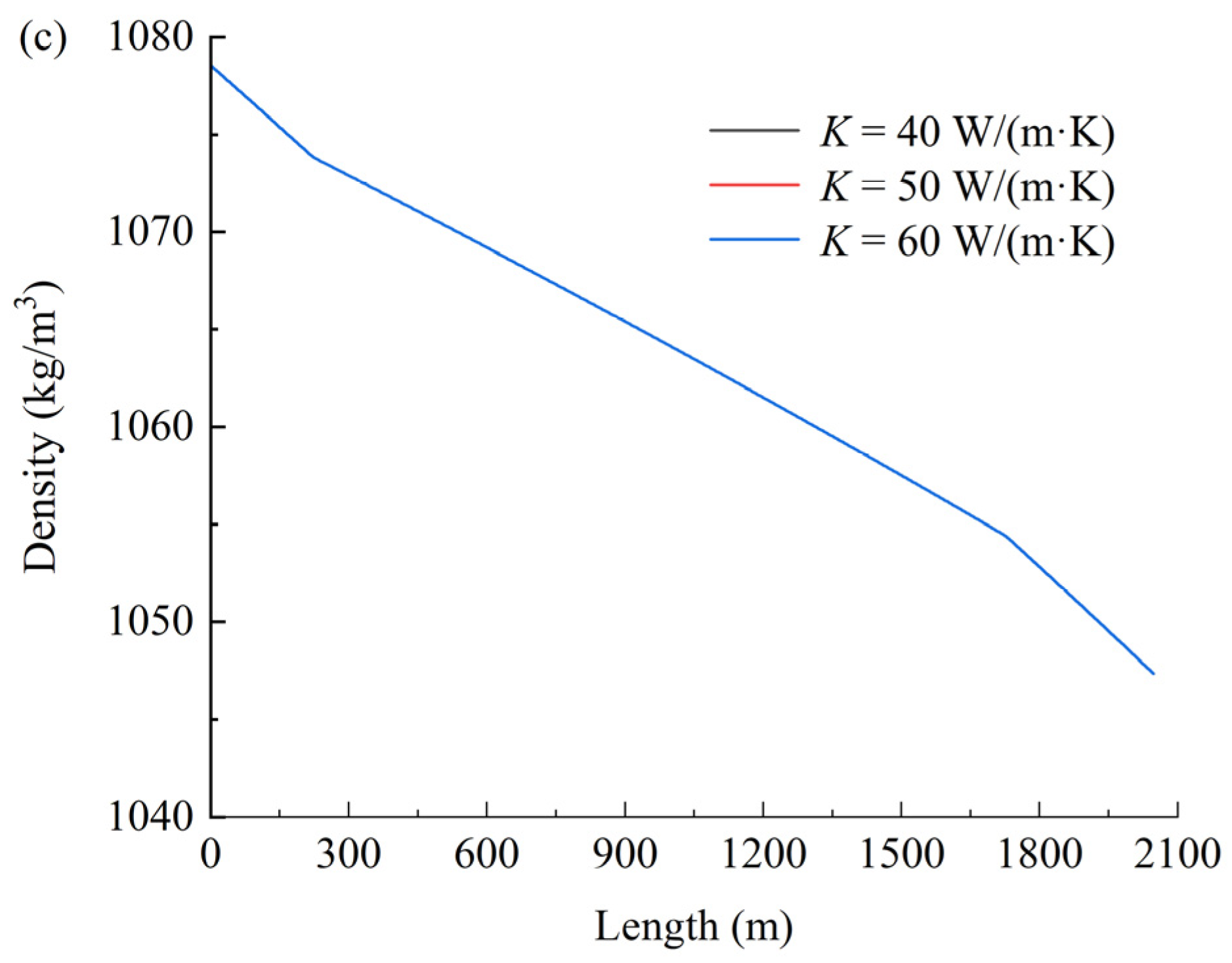
Figure 6 shows the effect of the thermal conductivity coefficient on temperature (a), pressure (b), and density (c). As shown in Figure 6, the thermal conductivity coefficient exhibits negligible influence on the temperature, pressure, and density of CO2 within the coiled tubing. This phenomenon may be attributed to the dominant role of turbulent mixing effects under forced convection conditions (Re > 2300), where the convective heat-transfer coefficient exceeds the thermal conductivity coefficient by 2–3 orders of magnitude. Consequently, the Nusselt number becomes predominantly governed by the hydrodynamic characteristics of the flow regime.
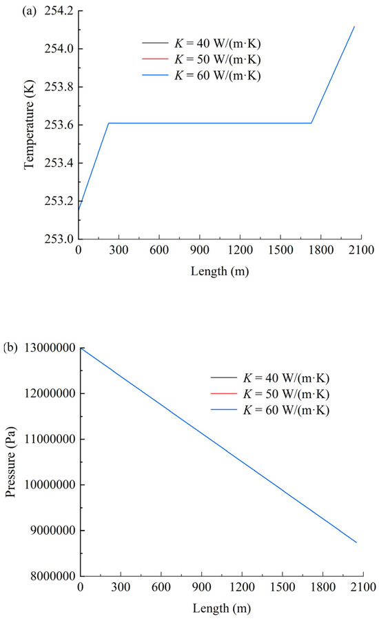
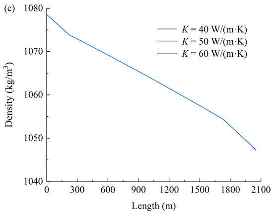
Figure 6.
Effect of the thermal conductivity coefficient on temperature (a), pressure (b), and density (c).
4.2. Friction Coefficient fCT
Figure 7 shows the effect of the friction coefficient on temperature (a), pressure (b), and density (c). As shown in Figure 7a, the friction coefficient exhibits negligible influence on temperature variations. In contrast, Figure 7b,c demonstrate that both the hydrodynamic pressure loss and the magnitude of CO2 density reduction increase significantly with rising friction coefficients. The observed increases in pressure loss and density reduction with higher friction coefficients primarily stem from intensified viscous dissipation and compressibility effects in supercritical CO2 flows. Elevated friction amplifies turbulent momentum transfer toward the pipe wall, increasing mechanical energy loss (manifested as pressure drop) while triggering stronger fluid expansion due to CO2’s pressure-sensitive density. The negligible temperature response arises from efficient convective heat dissipation that rapidly neutralizes frictional heating, maintaining thermal equilibrium with the environment.
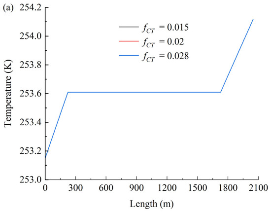
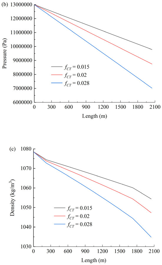
Figure 7.
Effect of the friction coefficient on temperature (a), pressure (b), and density (c).
5. Conclusions
The temperature of carbon dioxide at the exit increases gradually with the increase in coiled tubing length. The temperature change is no more than 1 K, due to the low temperature difference between the carbon dioxide and the air and the existence of an air interlayer and a low natural convective heat-transfer efficiency.
The flow pressure loss increases with increasing coiled tube length. The pressure losses of 848 m, 1448 m, and 2048 m helical coiled tubes are 1.76 MPa, 3.0 MPa, and 4.3 MPa, respectively, under the conditions stated herein. The flow pressure loss of carbon dioxide in the helical coiled tubing is half that of conventional drilling fluid in the same pipe due to the low viscosity of carbon dioxide.
The density of carbon dioxide as it flows through the helical coiled tubing changes from 1078 kg/m3 to 1047 kg/m3 with increasing coiled tube length under the conditions stated herein. The carbon dioxide remains liquid throughout this process. The reason for the density variation of carbon dioxide is that the pressure decreases and the temperature increases with the tube extension.
The thermal conductivity coefficient exhibits negligible influence on the temperature, pressure, and density of CO2 within the coiled tubing, which is attributed to the dominant role of turbulent mixing effects under forced convection conditions. The friction coefficient exhibits negligible influence on temperature variations; however, both the pressure loss and the magnitude of CO2 density reduction increase significantly with rising friction coefficients. The observed increases in pressure loss and density reduction with higher friction coefficients primarily stem from intensified viscous dissipation and compressibility effects in CO2 flows. The negligible temperature response arises from efficient convective heat dissipation that rapidly neutralizes frictional heating, maintaining thermal equilibrium with the environment.
This study does not account for the influence of thermal stratification or non-uniform heat transfer within layers. Interlayer thermal stratification and non-uniform heat transfer significantly alter the thermodynamic behavior of SC-CO2. Thermally, temperature gradients induce drastic variations in the thermophysical properties of SC-CO2, resulting in coexisting localized heat-transfer enhancement and deterioration. Concurrently, elevated Richardson numbers may compromise the applicability of forced convection correlations. Hydraulically, viscosity gradients and density stratification-driven secondary flows substantially amplify frictional pressure losses and trigger flow separation. These coupled effects intensify under near-critical conditions, potentially inducing thermal stress fatigue in tubing walls and dynamic pressure oscillations. Such phenomena pose dual challenges to the thermal efficiency and operational safety of continuous tubing systems, with severity modulated by flow distribution uniformity and wall roughness. Future investigations should employ multiphysics-coupled models and distributed fiber optic thermometry to quantify underlying mechanisms, while exploring mitigation strategies such as pulsating flow injection or helical ribbed geometries. The present study establishes engineering risk boundaries and provides theoretical foundations for optimizing SC-CO2-based thermodynamic cycles.
Author Contributions
Z.L. conceived and designed the program, analyzed the computed results, and wrote the paper. P.W. supervised the study and debugged the program. All authors have read and agreed to the published version of the manuscript.
Funding
This research was funded by Natural Science Foundation of Shandong Province (grant number ZR2022ME006), Scientific and Technological Project of Sinopec Oilfield Service Corporation (grant number SG23-08K), and Qingdao headstream innovation and applied basic research project (grant number 19-6-2-22-cg).
Data Availability Statement
We have included a data availability statement in our manuscript.
Conflicts of Interest
Author Zhixing Luan was employed by the Offshore Drilling Company of Sinopec Oilfield Service Shengli Corporation. The remaining authors declare that the research was conducted in the absence of any commercial or financial relationships that could be construed as a potential conflict of interest. The authors declare that this study received funding from Scientific and Technological Project of Sinopec Oilfield Service Corporation. The funder was not involved in the study design, collection, analysis, interpretation of data, the writing of this article or the decision to submit it for publication.
References
- Al-Adwani, F.; Langlinais, J.; Hughes, R. Modeling of an Underbalanced-Drilling Operation Using Supercritical Carbon Dioxide. SPE Drill. Complet. 2009, 24, 599–610. [Google Scholar] [CrossRef]
- Song, J.; Kim, H.Y.; Kim, H.; Bae, Y.Y. Heat transfer characteristics of a supercritical fluid flow in a vertical pipe. J. Supercrit. Fluids 2008, 44, 164–171. [Google Scholar] [CrossRef]
- Bruch, A.; Bontemps, A.; Colasson, S. Experimental investigation of heat transfer of supercritical carbon dioxide flowing in a cooled vertical tube. Int. J. Heat Mass Transf. 2009, 52, 2589–2598. [Google Scholar] [CrossRef]
- Schuler, M.J.; Rothenfluh, T.; von Rohr, R. Simulation of the thermal field of submerged supercritical water jets at near-critical pressures. J. Supercrit. Fluids 2013, 75, 128–137. [Google Scholar] [CrossRef]
- Ničeno, B.; Sharabi, M. Large eddy simulation of turbulent heat transfer at supercritical pressures. Nucl. Eng. Des. 2013, 261, 44–55. [Google Scholar] [CrossRef]
- Jiang, P.-X.; Shi, R.-F.; Xu, Y.-J.; He, S.; Jackson, J. Experimental investigation of flow resistance and convection heat transfer of CO2 at supercritical pressures in a vertical porous tube. J. Supercrit. Fluids 2006, 38, 339–346. [Google Scholar] [CrossRef]
- Cao, X.L.; Rao, Z.H.; Liao, S.M. Laminar convective heat transfer of supercritical CO2 in horizontal miniature circular and triangular tubes. Appl. Therm. Eng. 2011, 31, 2374–2384. [Google Scholar] [CrossRef]
- Withag, J.A.; Sallevelt, J.L.; Brilman, D.W.; Bramer, E.A.; Brem, G. Heat transfer characteristics of supercritical water in a tube: Application for 2D and an experimental validation. J. Supercrit. Fluids 2012, 70, 156–170. [Google Scholar] [CrossRef]
- Oh, H.-K.; Son, C.-H. New correlation to predict the heat transfer coefficient in-tube cooling of supercritical CO2 in horizontal macro-tubes. Exp. Therm. Fluid Sci. 2010, 34, 1230–1241. [Google Scholar] [CrossRef]
- Lee, H.-S.; Kim, H.-J.; Yoon, J.-I.; Choi, K.-H.; Son, C.-H. The cooling heat transfer characteristics of the supercritical CO2 in micro-fin tube. Heat Mass Transf. 2013, 49, 173–184. [Google Scholar] [CrossRef]
- Sivasankaran, S.; Bhuvaneswari, M. Numerical study on influence of water based hybrid nanofluid and porous media on heat transfer and pressure loss. Case Stud. Therm. Eng. 2022, 34, 102022. [Google Scholar] [CrossRef]
- Thomson, J.V. On the Origin of Windings of Rivers in Alluvial Plains, with Remarks on the Flow of Water round Bends in Pipes. Proc. R. Soc. Lond. 1877, 25, 5–8. [Google Scholar]
- Dean, W.R. Fluid Motion in a Curved Channel. Proc. R. Soc. Lond. Ser. A Contain. Pap. A Math. Phys. Character 1928, 121, 402–420. [Google Scholar]
- Janssen, L.A.M.; Hoogendoorn, C.J. Laminar convective heat transfer in helical coiled tubes. Int. J. Heat Mass Transf. 1978, 21, 1197–1206. [Google Scholar] [CrossRef]
- Cioncolini, A.; Santini, L. An experimental investigation regarding the laminar to turbulent flow transition in helically coiled pipes. Exp. Therm. Fluid Sci. 2006, 30, 367–380. [Google Scholar] [CrossRef]
- Cioncolini, A.; Santini, L. On the laminar to turbulent flow transition in diabatic helically coiled pipe flow. Exp. Therm. Fluid Sci. 2006, 30, 653–661. [Google Scholar] [CrossRef]
- White, C.M. Streamline Flow through Curved Pipes. Proc. R. Soc. Lond. Ser. A Contain. Pap. A Math. Phys. Character 1929, 123, 645–663. [Google Scholar]
- Zhou, Y.; Shah, S. Fluid Flow in Coiled Tubing: A Literature Review and Experimental Investigation. J. Can. Pet. Technol. 2004, 43, 52–61. [Google Scholar] [CrossRef]
- Moawed, M. Experimental study of forced convection from helical coiled tubes with different parameters. Energy Convers. Manag. 2011, 52, 1150–1156. [Google Scholar] [CrossRef]
- Ito, H. Friction factors for turbulent flow in curved pipes. J. Basic Eng. 1959, 81, 123–124. [Google Scholar] [CrossRef]
- Srinivasan, P.S.; Nandapurkar, S.S.; Holland, F.A.J.C.E. Pressure drop and heat transfer in coils. Chem. Eng. 1968, 218, 113–119. [Google Scholar]
- Ferng, Y.M.; Lin, W.C.; Chieng, C.C. Numerically investigated effects of different Dean number and pitch size on flow and heat transfer characteristics in a helically coil-tube heat exchanger. Appl. Therm. Eng. 2012, 36, 378–385. [Google Scholar] [CrossRef]
- Jayakumar, J.S.; Mahajani, S.M.; Mandal, J.C.; Iyer, K.N.; Vijayan, P.K. CFD analysis of single-phase flows inside helically coiled tubes. Comput. Chem. Eng. 2010, 34, 430–446. [Google Scholar] [CrossRef]
- Chen, C.-N.; Han, J.-T.; Jen, T.-C.; Shao, L. Thermo-chemical characteristics of R134a flow boiling in helically coiled tubes at low mass flux and low pressure. Thermochim. Acta 2011, 512, 163–169. [Google Scholar] [CrossRef]
- Owhadi, A.; Bell, K.J. Forced convection boiling inside helically-coiled tubes. Int. J. Heat Mass Transf. 1967, 10, 397–401. [Google Scholar] [CrossRef]
- Jamshidi, N.; Farhadi, M.; Sedighi, K.; Ganji, D.D. Optimization of design parameters for nanofluids flowing inside helical coils. Int. Commun. Heat Mass Transf. 2012, 39, 311–317. [Google Scholar] [CrossRef]
- Akbaridoust, F.; Rakhsha, M.; Abbassi, A.; Saffar-Avval, M. Experimental and numerical investigation of nanofluid heat transfer in helically coiled tubes at constant wall temperature using dispersion model. Int. J. Heat Mass Transf. 2013, 58, 480–491. [Google Scholar] [CrossRef]
- Haruki, N.; Horibe, A. Flow and heat transfer characteristics of ice slurries in a helically-coiled pipe. Int. J. Refrig. 2013, 36, 1285–1293. [Google Scholar] [CrossRef]
- Di Piazza, I.; Ciofalo, M. Numerical prediction of turbulent flow and heat transfer in helically coiled pipes. Int. J. Therm. Sci. 2010, 49, 653–663. [Google Scholar] [CrossRef]
- Bergman, T.L.; Lavine, A.S.; Incropera, F.P.; De Witt, D.P. Fundamentals of Heat and Mass Transfer, 8th ed.; Wiley: Hoboken, NJ, USA, 2021. [Google Scholar]
- Rao, B. Coiled Tubing Hydraulics Modeling; Tech Note; CTES, L.C.: Conroe, TX, USA, 1999; Available online: https://ctes.nov.com/Documentation/technotes/Tech%20Note%20Basic%20Hydraulics.pdf (accessed on 12 April 2025).
- Hasan, A.R.; Kabir, C.S. Aspects of Wellbore Heat Transfer During Two-Phase Flow. SPE Prod. Facil. 1994, 9, 211–216. [Google Scholar] [CrossRef]
- Ramey, H.J. Wellbore Heat Transmission. J. Pet. Technol. 1962, 14, 427–435. [Google Scholar] [CrossRef]
- Holmes, C.S.; Swift, S.C. Calculation of Circulating Mud Temperatures. J. Pet. Technol. 1970, 22, 670–674. [Google Scholar] [CrossRef]
- McCann, R.C.; Islas, C.G. Frictional Pressure Loss During Turbulent Flow in Coiled Tubing. In Proceedings of the SPE Gulf Coast Section/ICoTA North American Coiled Tubing Roundtable, Conroe, TX, USA, 26 February 1996. [Google Scholar]


Disclaimer/Publisher’s Note: The statements, opinions and data contained in all publications are solely those of the individual author(s) and contributor(s) and not of MDPI and/or the editor(s). MDPI and/or the editor(s) disclaim responsibility for any injury to people or property resulting from any ideas, methods, instructions or products referred to in the content. |
© 2025 by the authors. Licensee MDPI, Basel, Switzerland. This article is an open access article distributed under the terms and conditions of the Creative Commons Attribution (CC BY) license (https://creativecommons.org/licenses/by/4.0/).