
Design and Adaptability Analysis of Integrated Pressurization–Gas Lifting Multifunctional Compressor for Enhanced Shale Gas Production Flexibility

Abstract
1. Introduction
1.1. Motivation
1.2. Literature Review
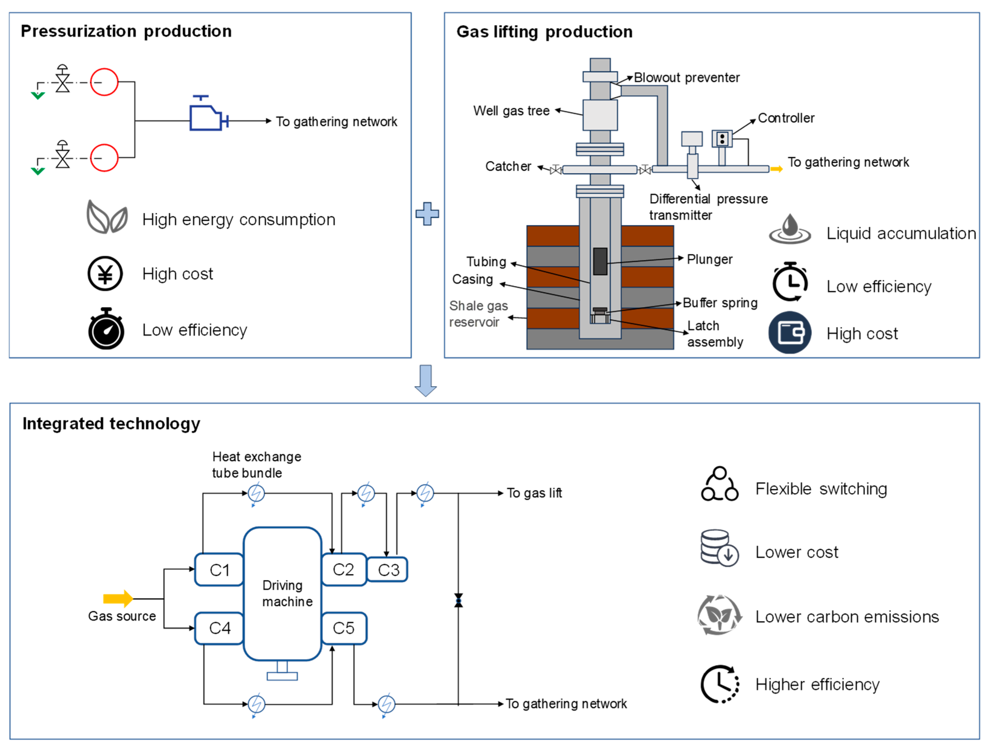
- Current shale gas platform development predominantly adopts either pressurization production or gas lifting production independently, lacking research on the integrated gas lifting and pressurization composite process, which hinders efficient production on shale gas platforms;
- Although some scholars have focused on the development of platform equipment configurations, most of the research is limited to setups for single production modes, resulting in decreased production efficiency;
- Few scholars have conducted adaptability analyses of pressurization and gas lifting systems on platforms.

| Ref. | Shale Gas Development | Pressurization Production | Gas Lifting Production | ||
|---|---|---|---|---|---|
| Device Design | Adaptability Analysis | Device Design | Adaptability Analysis | ||
| Guarnone et al. [1] | √ | √ | |||
| Hong et al. [2] | √ | √ | |||
| Zagorowska et al. [9] | √ | ||||
| Zhou et al. [10] | √ | √ | √ | ||
| Liu et al. [11] | √ | ||||
| Abbasov and Kerimova [15] | |||||
| Fan et al. [16] | √ | √ | |||
| Jin et al. [17] | √ | √ | |||
| Altarabulsi and Waltrich [21] | √ | ||||
| Tang et al. [22] | √ | ||||
| This paper | √ | √ | √ | √ | √ |
1.3. Research Objectives and Scope
1.4. Paper Organization
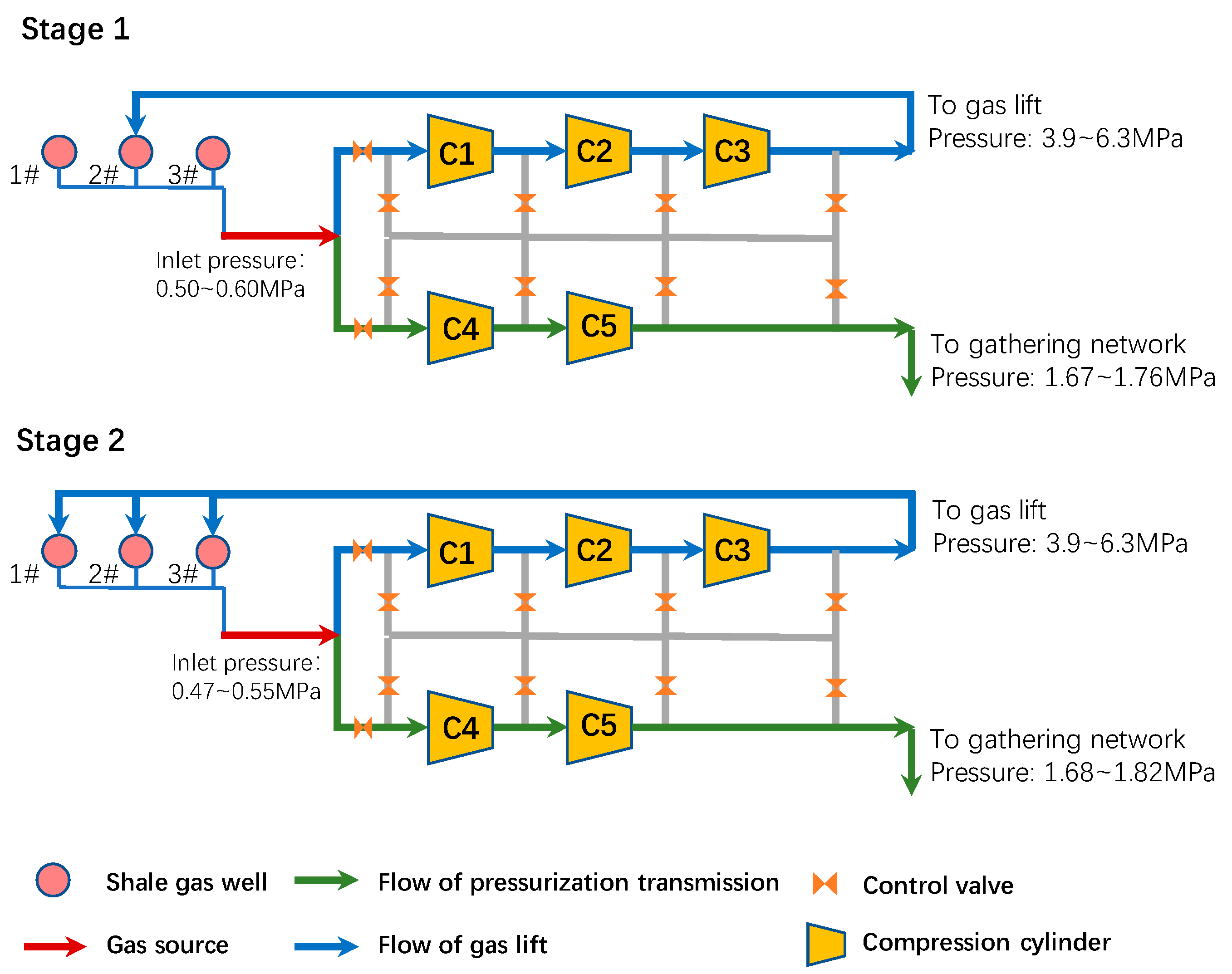
2. Process Description
3. Compressor
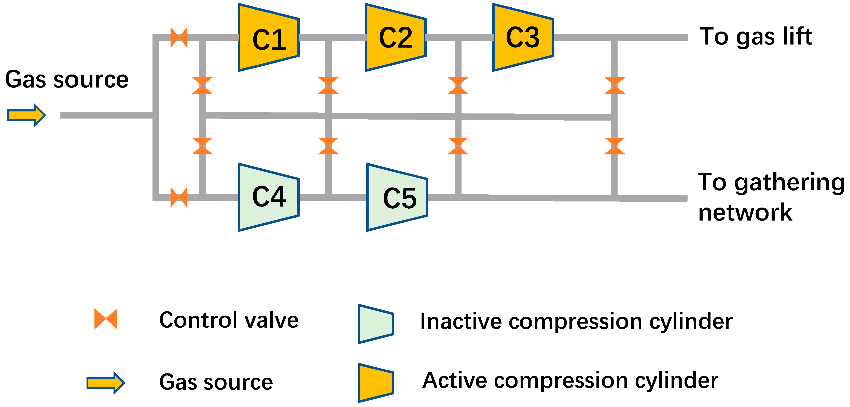
3.1. Operational Characteristics
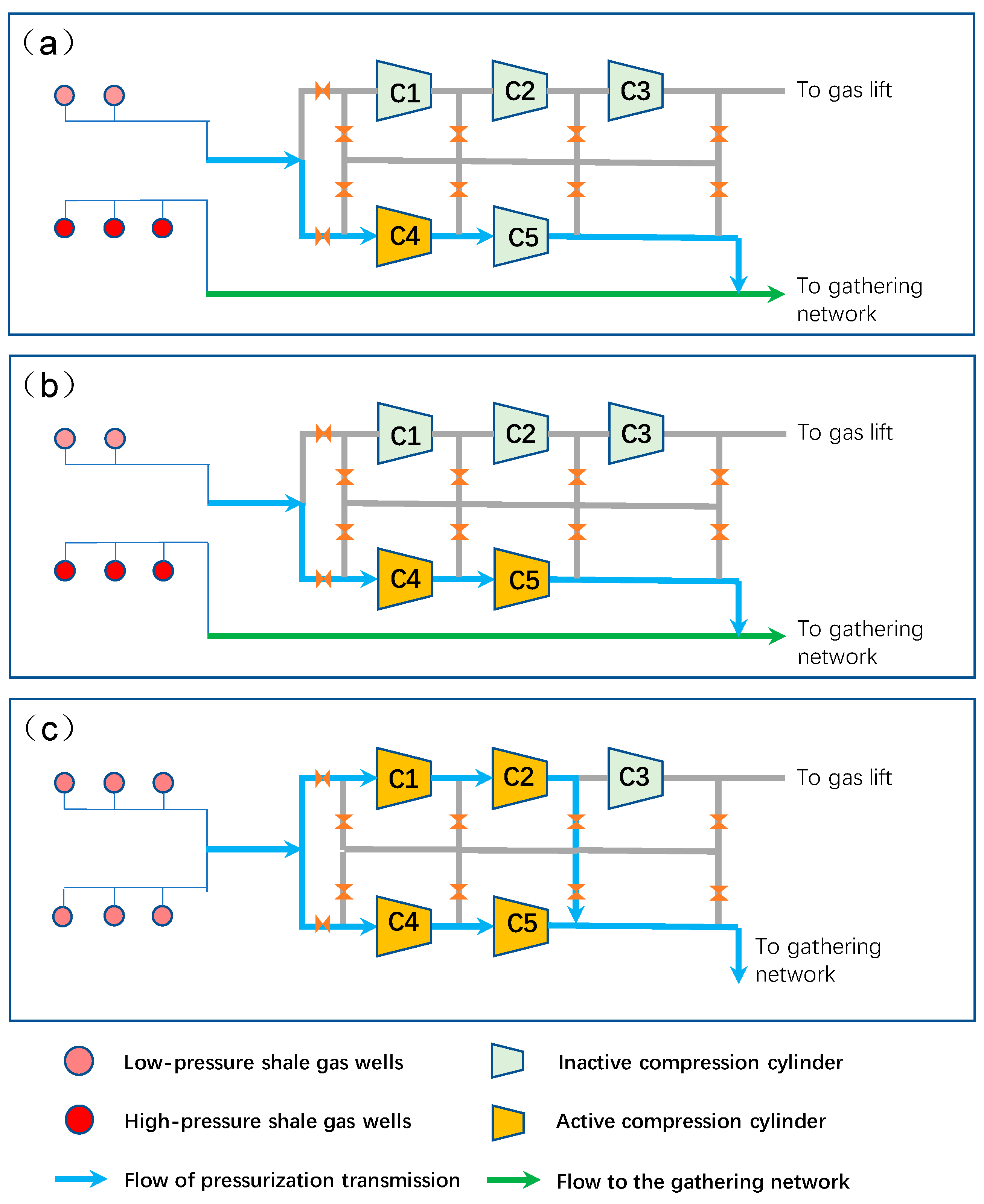
3.2. Function
- (1)
- Gas Lifting Function
- (2)
- Pressurization function
- (3)
- Pressurization and gas lifting function
4. Methodology
- (1)
- Gas lifting process
- (2)
- Pressurization process
- (3)
- Pressurization and gas lifting process
5. Case Studies
5.1. Case Description
5.2. Case 1
- (1)
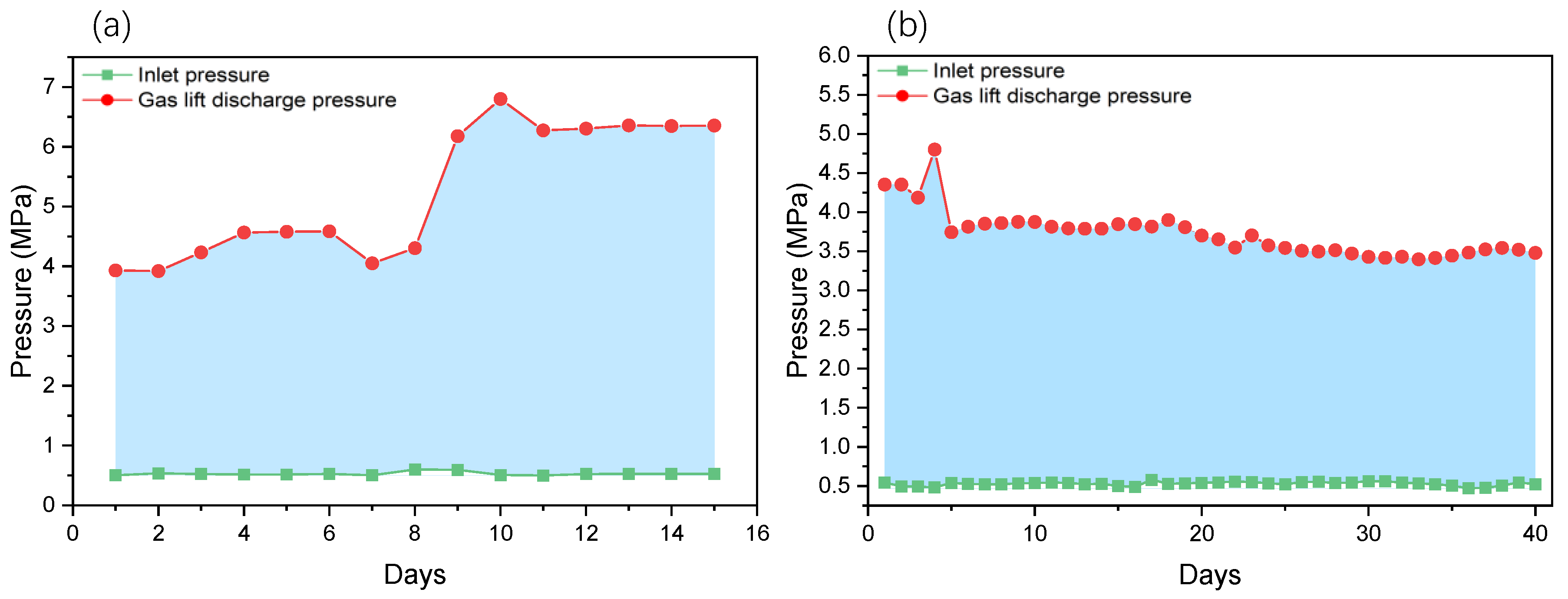
- Gas lifting production adaptability analysis
- (2)
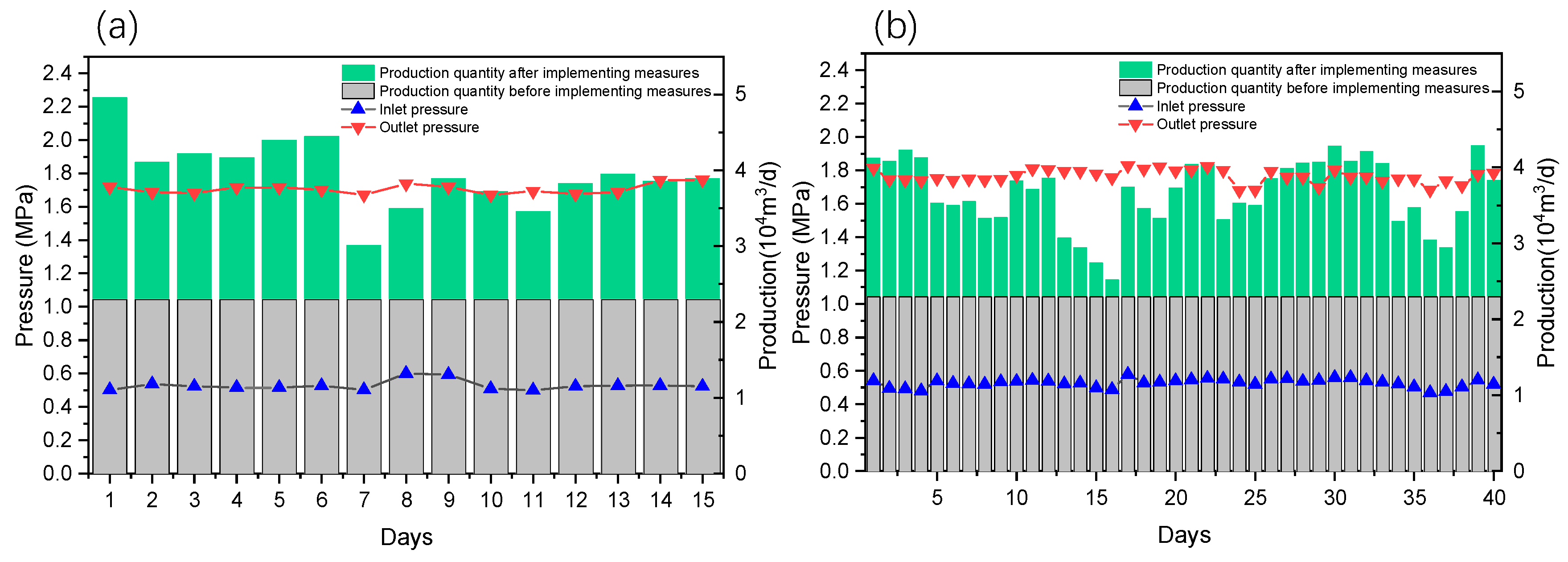
- Pressurization production adaptability analysis
- (3)
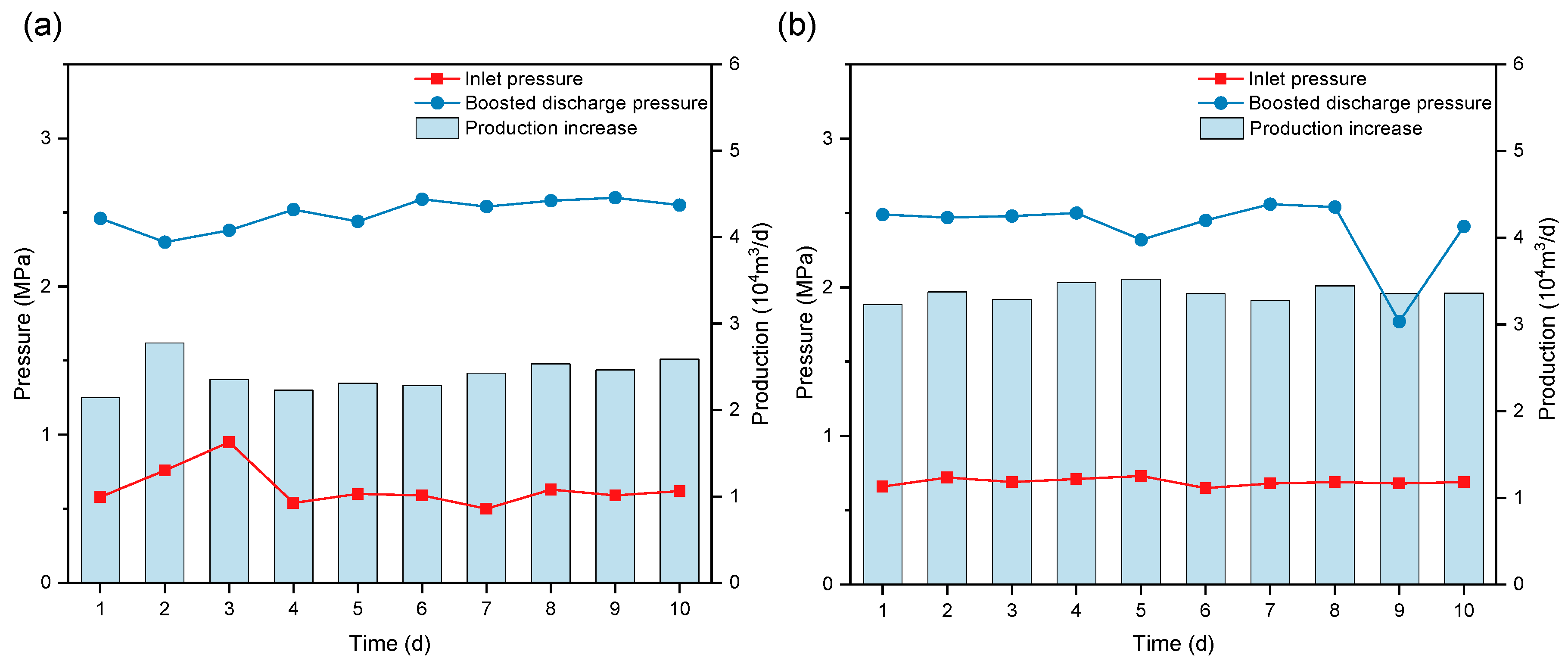
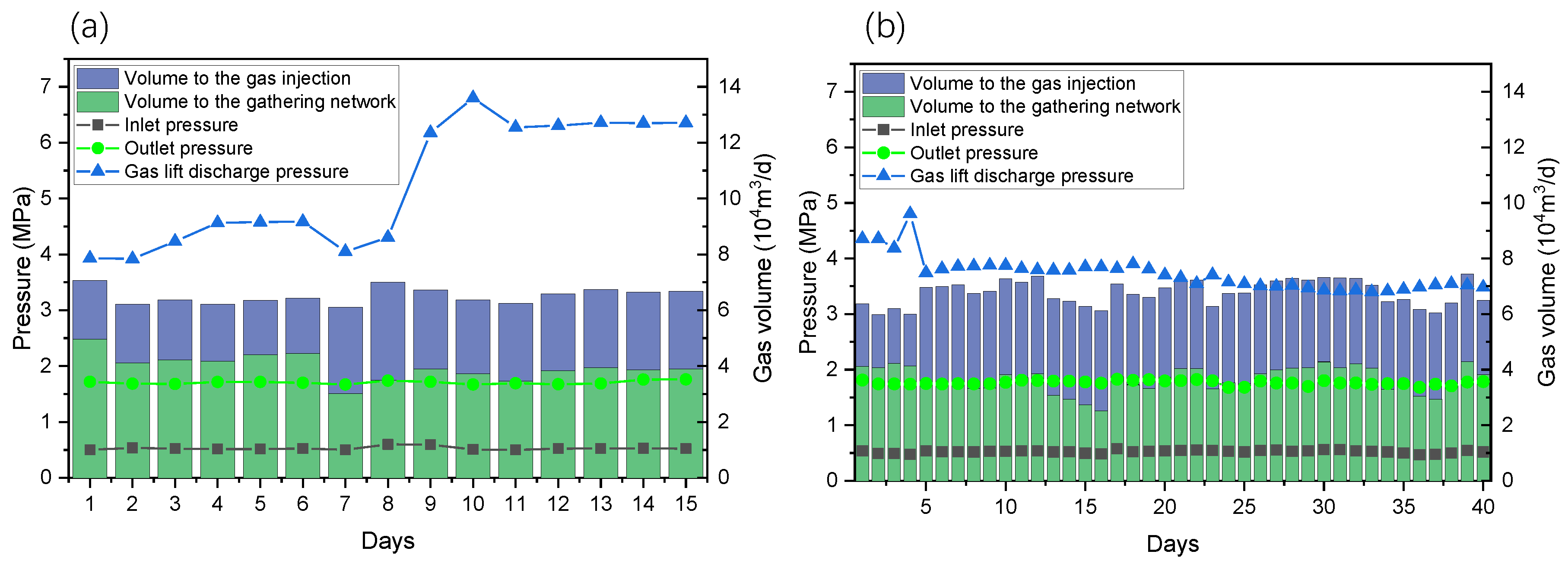
- Pressurization and gas lifting production adaptability analysis
- (4)
- Compressor analysis
- (5)
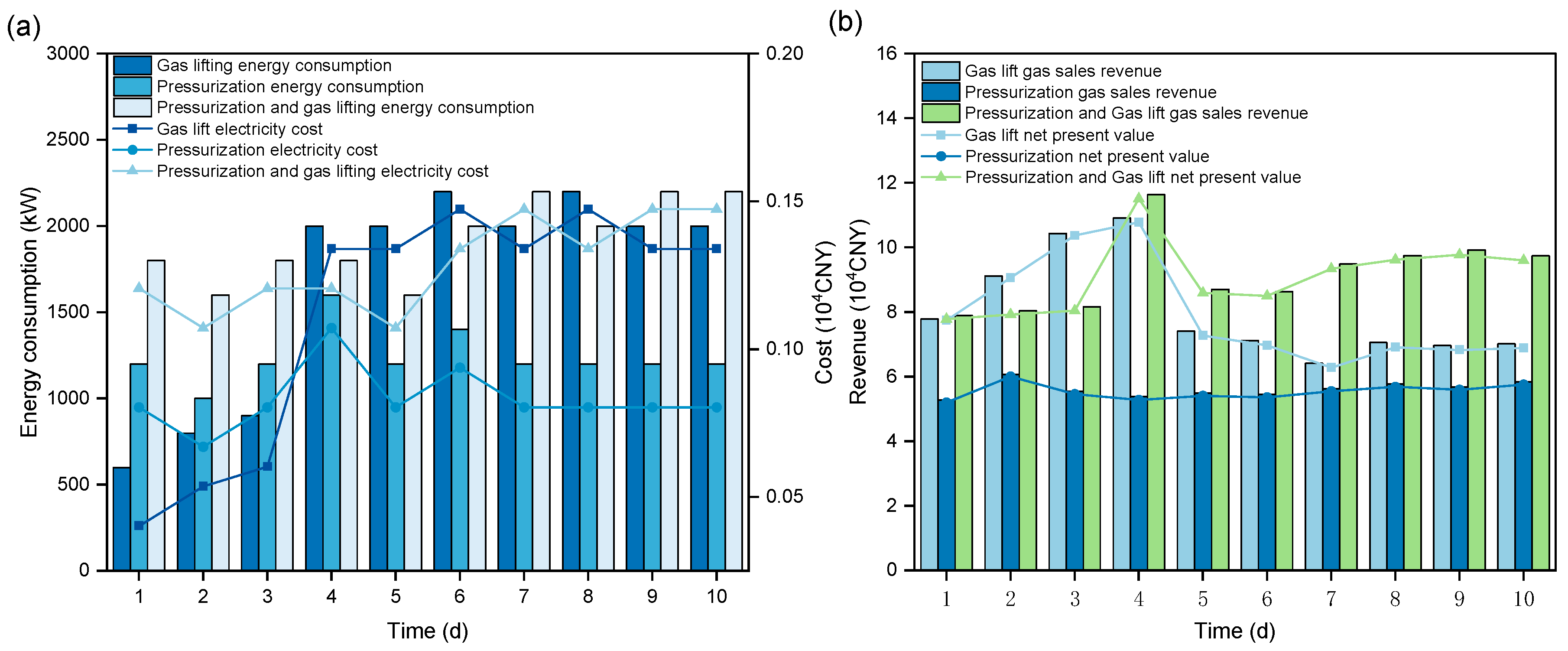
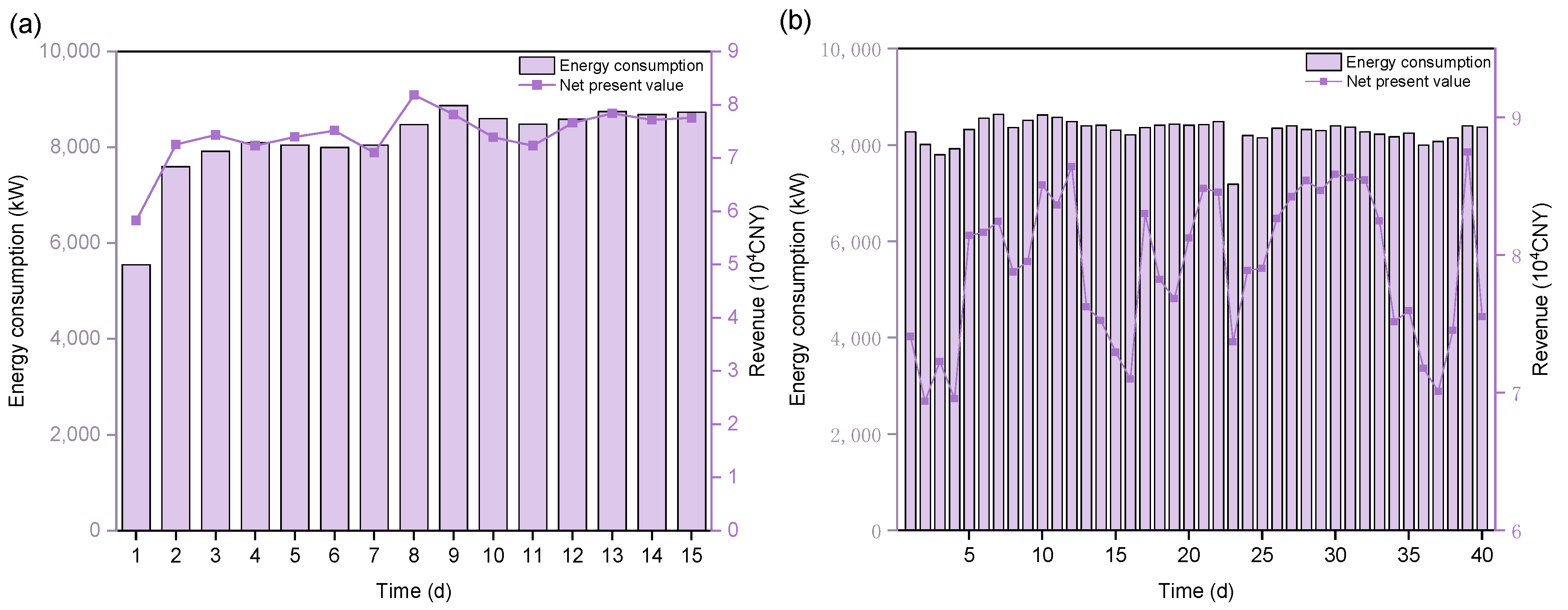
- Economic analysis
5.3. Case 2
- (1)
- Gas lifting production adaptability analysis
- (2)
- Pressurization production adaptability analysis
- (3)
- Pressurization and gas lifting production adaptability analysis
- (4)
- Economic analysis
6. Conclusions
- (1)
- This study successfully developed an integrated pressurization–gas lifting dual-function compressor, which enhances the equipment’s adaptability and flexibility under different operating conditions by optimizing the gas flow design and control strategies, meeting complex production demands. The equipment can flexibly switch operational modes based on the platform’s actual needs, ensuring efficient and stable operation.
- (2)
- The integrated compressor unit enhances gas lift operation efficiency through multi-stage compression and high-pressure gas output, effectively addressing the issue of liquid accumulation and ensuring stable production. The high-power motor of the compressor ensures an efficient and stable gas compression process, boosting production capacity, promoting the long-term stable exploitation of oil and gas fields, and maintaining a high recovery rate.
- (3)
- By combining the gas lifting and pressurization functions, this process effectively increases gas well production and resolves issues related to low pressure and liquid accumulation. Field test results indicate that under gas lifting mode, the equipment significantly improves the production conditions of gas wells; under pressurization mode, the equipment stably outputs the required pressure, ensuring continuous production on the platform.
- (4)
- The integrated compressor unit design reduces the number of devices, lowers construction and maintenance costs, and improves energy utilization efficiency. At the same time, the equipment shows significant advantages in reducing carbon emissions, providing strong support for the sustainable development of shale gas fields.
- (5)
- The process and equipment solutions proposed in this study can be widely applied to various shale gas platforms, particularly in multi-well joint extraction and complex gas source development environments. The new equipment not only meets the demands of shale gas development across its entire lifecycle but also provides technical assurance for efficient development and long-term operation. In conclusion, the integrated pressurization–gas lifting dual-function compressor process offers an innovative, economical, and environmentally friendly solution for shale gas extraction, playing an important role in enhancing shale gas field production efficiency, reducing operational costs, and driving energy structure transformation. It has significant practical implications and broad application prospects.
Author Contributions
Funding
Data Availability Statement
Acknowledgments
Conflicts of Interest
References
- Guarnone, M.; Rossi, F.; Negri, E. An unconventional mindset for shale gas surface facilities. J. Nat. Gas Sci. Eng. 2012, 6, 14–23. [Google Scholar] [CrossRef]
- Hong, B.; Li, X.; Song, S.; Chen, S.; Zhao, C.; Gong, J. Optimal planning and modular infrastructure dynamic allocation for shale gas production. Appl. Energy 2020, 261, 114439. [Google Scholar] [CrossRef]
- Drouven, M.G.; Grossmann, I.E. Multi-period planning, design, and strategic models for long-term, quality-sensitive shale gas development. AIChE J. 2016, 7, 2296–2323. [Google Scholar] [CrossRef]
- Drouven, M.G.; Grossmann, I.E. Mixed-integer programming models for line pressure optimization in shale gas gathering systems. J. Pet. Sci. Eng. 2017, 157, 1021–1032. [Google Scholar] [CrossRef]
- Soni, A.; Linderoth, J.; Luedtke, J.; Rigterink, F. Mixed-integer linear programming for scheduling unconventional oil field development. Optim. Eng. 2021, 22, 1459–1489. [Google Scholar] [CrossRef]
- Peng, Z.; Li, C.; Grossmann, I.E.; Kwon, K.; Ko, S.; Shin, J.; Feng, Y. Shale gas field development planning under production profile uncertainty. AIChE J. 2022, 68, e17439. [Google Scholar] [CrossRef]
- Krishnaswami, P.; Chapman, K.S.; Abbaspour, M. Compressor station optimization for linepack maintenance. In Proceedings of the 36th Pipeline Simulation Interest Group Annual Meeting, Palm Springs, CA, USA, 20–22 October 2004. [Google Scholar]
- Martin, A.; Möller, M.; Moritz, S. Mixed integer models for the stationary case of gas network optimization. Math Program 2006, 105, 563–582. [Google Scholar] [CrossRef]
- Zagorowska, M.; Skourup, C.; Thornhill, N.F. Influence of compressor degradation on optimal operation of a compressor station. Comput. Chem. Eng. 2020, 143, 0098–1354. [Google Scholar] [CrossRef]
- Zhou, J.; Zhang, H.; Li, Z.; Liang, G. A MINLP model for combination pressurization optimization of shale gas gathering system. J. Pet. Explor. Prod. Technol. 2022, 12, 3059–3075. [Google Scholar] [CrossRef]
- Liu, K.; Biegler, L.T.; Zhang, B.; Chen, Q. Dynamic optimization of natural gas pipeline networks with demand and composition uncertainty. Chem. Eng. Sci. 2019, 215, 115449. [Google Scholar] [CrossRef]
- Sanaye, S.; Mahmoudimehr, J. Optimal design of a natural gas transmission network layout. Chem. Eng. Res. Des. 2013, 91, 2465–2476. [Google Scholar] [CrossRef]
- Borraz-Sánchez, C. Optimization Methods for Pipeline Transportation of Natural Gas. Ph.D. Thesis, University of Bergen, Bergen, Norway, 2010. [Google Scholar]
- Frimannslund, L.; Haugland, D. Line pack management for improved regularity in pipeline gas transportation networks. Saf. Reliab. Risk Anal. Theory Methods Appl. 2008, 4, 2963–2969. [Google Scholar]
- Abbasov, E.; Kerimova, S.A. Gas Hydrodynamic Modeling of Operation of Intermittent Gas Lifts. J. Eng. Thermophys. 2023, 32, 256–278. [Google Scholar] [CrossRef]
- Fan, Y.; Xiang, J.; Li, B.; Chen, J.; Jiang, M.; Yu, F. Applicability evaluation of plunger lift technology in shale gas wells. Front. Energy Res. 2024, 11, 1343724. [Google Scholar] [CrossRef]
- Jin, M.; Emami-Meybodi, H.; Ahmadi, M. Flowing Bottomhole Pressure during Gas Lift in Unconventional Oil Wells. In Proceedings of the SPE Annual Technical Conference and Exhibition, San Antonio, TX, USA, 16–18 October 2023. [Google Scholar]
- Miao, S.; Liu, X.; Feng, X.; Shi, H.; Luo, W.; Liu, P. A Dynamic Plunger Lift Model for Shale Gas Wells. Fluid Dyn. Mater. Process 2023, 19, 1735–1751. [Google Scholar] [CrossRef]
- Ohia, N.P.; Paul, C.; Asolo, E.; Adewa, T.A.; Chukwu, C.F.; Ubi, P.A.; Itam, D.H.; Nnaji, D.U. Artificial Intelligence-Driven Fuzzy Logic Approach for Optimal Well Selection in Gas Lift Optimization: A Brown Field Case Study. Results Eng. 2025, 25, 103927. [Google Scholar] [CrossRef]
- Aranha Ribeiro, J.B.; Vergara-Dietrich, J.D.; Normey-Rico, J.E. Comparison of Economic Model Predictive Controllers for Gas-Lift Optimization in Offshore Oil and Gas Rigs. Comput. Chem. Eng. 2024, 186, 108685. [Google Scholar] [CrossRef]
- Altarabulsi, K.; Waltrich, P. An Improved Method to Calculate Gas-Lift Valve Set Pressure. SPE J. 2024, 29, 5452–5463. [Google Scholar] [CrossRef]
- Tang, Y.; Zhang, Y.; He, Y.; Zhou, Y.; Zhao, P.; Wang, G. Study on multi-stage adjust mechanism of downhole stratification control tool for natural gas hydrate multi-gas combined production gas lift. Int. J. Hydrogen Energy 2024, 72, 800–814. [Google Scholar] [CrossRef]


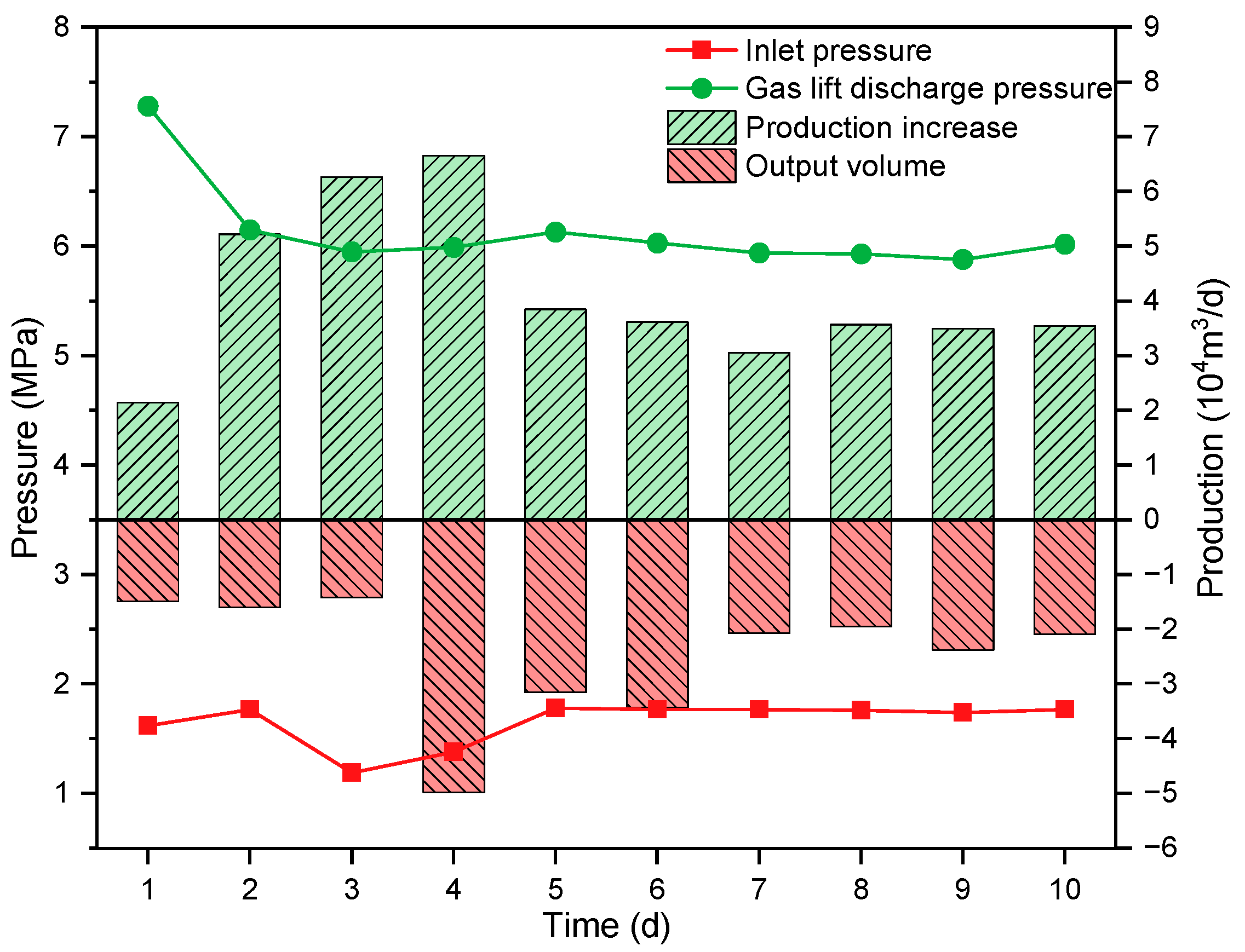


| Production Stage | Inlet Pressure (MPa) | Output Pressure (MPa) |
|---|---|---|
| Normal | 1.74~1.78 | 1.74~1.78 |
| Gas lift | 1.19~1.77 | 5.88~7.28 |
| Pressurization | 0.50~1.10 | 1.77~2.58 |
| Pressurization and gas lift | 0.59~1.78 | 2.27~5.42 |
Disclaimer/Publisher’s Note: The statements, opinions and data contained in all publications are solely those of the individual author(s) and contributor(s) and not of MDPI and/or the editor(s). MDPI and/or the editor(s) disclaim responsibility for any injury to people or property resulting from any ideas, methods, instructions or products referred to in the content. |
© 2025 by the authors. Licensee MDPI, Basel, Switzerland. This article is an open access article distributed under the terms and conditions of the Creative Commons Attribution (CC BY) license (https://creativecommons.org/licenses/by/4.0/).
Share and Cite
Wu, K.; Qu, L.; Zhou, J.; He, Y.; Wu, Y.; Zhou, Z.; Qin, C.; Chen, L.; Zhang, C. Design and Adaptability Analysis of Integrated Pressurization–Gas Lifting Multifunctional Compressor for Enhanced Shale Gas Production Flexibility. Processes 2025, 13, 1233. https://doi.org/10.3390/pr13041233
Wu K, Qu L, Zhou J, He Y, Wu Y, Zhou Z, Qin C, Chen L, Zhang C. Design and Adaptability Analysis of Integrated Pressurization–Gas Lifting Multifunctional Compressor for Enhanced Shale Gas Production Flexibility. Processes. 2025; 13(4):1233. https://doi.org/10.3390/pr13041233
Chicago/Turabian StyleWu, Kunyi, Lin Qu, Jun Zhou, Yan He, Yu Wu, Zonghang Zhou, Can Qin, Longyu Chen, and Chenqian Zhang. 2025. "Design and Adaptability Analysis of Integrated Pressurization–Gas Lifting Multifunctional Compressor for Enhanced Shale Gas Production Flexibility" Processes 13, no. 4: 1233. https://doi.org/10.3390/pr13041233
APA StyleWu, K., Qu, L., Zhou, J., He, Y., Wu, Y., Zhou, Z., Qin, C., Chen, L., & Zhang, C. (2025). Design and Adaptability Analysis of Integrated Pressurization–Gas Lifting Multifunctional Compressor for Enhanced Shale Gas Production Flexibility. Processes, 13(4), 1233. https://doi.org/10.3390/pr13041233