Article

Closed-Loop Solar Tracking Control Strategy to Correct Drift in a CPV System Using Image Processing

by
Héctor González-Camarillo
1,
Carlos A. Pérez-Rábago
1,
Ramiro Calleja-Valdez
2,
Ricardo Arturo Pérez-Enciso
3,
Rafael García-Gutiérrez
4,
Claudio A. Estrada-Gasca
1 and
Yuridiana R. Galindo-Luna
5,*
1
Instituto de Energías Renovables, Universidad Nacional Autónoma de MéxicoPriv. Xochicalco, Temixco 62580, Mexico
2
Depertamento de Ingeniería Química y Metalurgia, Facultad Interdisciplinaria de Ingeniería, Universidad de Sonora, Blv. Encinas y Rosales, Hermosillo 83000, Mexico
3
Depertamento de Ingeniería Industrial, Facultad Interdisciplinaria de Ingeniería, Universidad de Sonora, Blv. Encinas y Rosales, Hermosillo 83000, Mexico
4
Depertamento de Física, Facultad Interdisciplinaria de Ciencias Exactas y Naturales, Universidad de Sonora, Blv. Encinas y Rosales, Hermosillo 83000, Mexico
5
Departamento de Ingeniería de Procesos e Hidráulica, División de Ciencias Básicas e Ingeniería, Universidad Autónoma Metropolitana Iztapalapa, Av. Ferrocaril San Rafael Atlixco 186, Col. Leyes de Reforma 1 A Sección, Ciudad de Mexico 09310, Mexico
*
Author to whom correspondence should be addressed.
Processes 2025, 13(4), 944; https://doi.org/10.3390/pr13040944
Submission received: 17 January 2025 / Revised: 2 March 2025 / Accepted: 20 March 2025 / Published: 22 March 2025

Abstract

:
Tracking the apparent movement of the sun with high precision is crucial in dual-axis tracking systems for solar concentration applications. It is important to develop control strategies to reduce losses by solar radiation displacement (drift) on the receiver and improve the solar concentration system. In concentrated photovoltaics, a high-precision tracking control is required to keep the concentration point. This paper compares open-loop and closed-loop solar tracking control strategies to solve drift problems and correct azimuth and elevation angles in a non-image reflective FRESNEL solar concentrator. The open-loop strategy consists of a programming code to calculate the apparent sun position, sending command signals to the actuator systems in azimuth and elevation tracker axes. In the open-loop strategy, the actual position of the sun is not verified. A closed-loop strategy with a visual monitoring device is proposed here to detect the sun’s position in real time. This can be simultaneously compared with a fixed reference to evaluate drift through time, calculate the generated error, and send feedback signals to correct azimuth and elevation angles. With this configuration, displacement containment of the solar point concentration projection was ±0.00215 m in the azimuth direction and ±0.0027 m in the elevation direction on the receiver.

1. Introduction

Sun energy is the most used renewable energy since it is available on the entire surface of the planet. Direct solar radiation from the sun arrives on Earth’s surface as heat and light, and with capturing, transforming, and storage technologies, it can be converted into useful energy for industrial, residential, and other sectors.
An important issue about solar radiation is the continuous changes in the sun’s relative position in the sky due to Earth’s rotation around its axis and its orbit around the sun, generating daily and annual cycles. This fact means that part of the solar radiation is lost when a fixed position configuration is used in solar tracking systems [1]. For this reason, capturing solar radiation technologies for power generation requires a high-precision tracking system to control alignment with the sun’s apparent position. A suitable orientation and position of the solar energy collector system improves performance, and the needed area to install it is optimized since the generated energy increases, compared with a fixed configuration system. That is, technologies such as photovoltaic (PV), concentration photovoltaic (CPV), and solar thermal systems could be improved [2].
Since 2010, solar photovoltaics have presented the most rapid cost reductions. According to IRENA [3], the weighted average cost of solar photovoltaic electricity at the utility scale for several countries in a period from 2010 to 2023 reported that the cost in Australia decreased by 93% to USD 0.034/kWh. China achieved USD 0.036/kWh, a corresponding decline of 89%. Chile obtained third place and was the most competitive among historical markets at USD 0.036/kWh; for Spain, the behavior is similar, decreasing 18% and reaching USD 0.038/kWh. CPV technology can achieve conversion efficiencies of up to 30% with respect to PV [4]. Italy showed cost reduction between 2011 and 2019 to four power sizes <10 kW, 10–100 kW, 100–250 kW, and 10–20 MW related to the unit cost (EUR/W). In the first case, the cost varies in a range from 6.68/W to 2.88 EUR/W, and in the last case, it was between 2.76 EUR/W and 1.07 EUR/W [5].
In recent years, several technologies have been developed to increase captured solar radiation, using direct and indirect techniques, including solar tracking systems [6]. Solar tracking is used to keep a solar energy system (photovoltaic or thermal) in a perpendicular position to the sun, increasing the energy collected as it receives the maximum solar radiation. There are two main types of solar tracking systems, which are classified according to solar axis: single-axis tracking configurations, tracking the sun’s movement east–west, and two-axis configurations, also tracking the elevation angle [7], improving the solar system efficiency.
Control systems are used to detect and track the sun’s position. In addition, they manage daily operation tasks, including calculating the monitoring set point, communication management, fault or error diagnosis, drive control, and decision-making in emergency situations [1].
There are three main methodologies for sun tracking: passive systems, open-loop systems, and closed-loop systems. Passive control systems make a solar position prediction using material properties (pressure control, mechanical provisions, and thermal expansion); therefore, electronic sensors or actuators are not required. Passive systems are reliable, simple in design, and need minimum maintenance; however, they do not calculate the sun’s position accurately, especially on cloudy days [8,9,10,11]. In open-loop control systems, a microprocessor calculates the apparent sun position using algorithms or mathematical models to send a signal command to the actuators in one or two axes. These systems use geographic location and standard time; thus, weather conditions do not affect the calculated sun position [9,12]. Since open-loop control systems do not include sensors, system errors and disturbances cannot be corrected [13]. Closed-loop systems combine optical sensors to increase precision in calculating the sun’s position, and along with the open-loop methodology, the amount of solar radiation captured ultimately increases [13,14,15,16,17]. Information provided by the optical sensors is sent to a controller to generate a differential control output signal orienting the tracking system [8,18,19,20,21]. Closed-loop systems increase solar energy systems performance, and several solar tracking control techniques with closed-loop methodologies have been developed, combining optical devices and programming codes for image analysis. Ahmed et al. [22] reported a solar tracking system integrated by a Raspberry Pi 4 card (Raspberry Pi, Cambridge, England) and an ATmega 128 microcontroller (Microchip Technology Inc., Chandler, AZ, USA). This system distinguishes between sun images and cloud images. Garcia-Gil and Ramirez [23] used panoramic images captured by a digital camera with fisheye optics to estimate azimuth and elevation angles. El Jaouhari et al. [2] calculated the sun’s position in azimuth and elevation angles in real time using hemispherical images of the sky. An output signal is generated with this information and sent to the tracking system. The advantage of this system is its high brightness sensitivity compared to traditional trackers based on photosensors. Abdollahpour et al. [24] proposed a control strategy for a biaxial tracker to maximize incident radiation on a photovoltaic panel using image processing. According to the author’s results, the sun tracking angle was optimized by ± 2°. In a review of various control algorithms applied to active solar tracking systems [25], a comparative analysis was carried out between open-loop, closed-loop, and hybrid control systems, as is the case in the present study. Most works on open-loop control report accuracy in a range of 0.6° to 0.1°. In the case of closed-loop systems, accuracy varies between 7.5° and 0.1°. Finally, for hybrid control systems, accuracies have been recorded in a range of 0.15° to 0.1°.
To improve object detection and location, new techniques such as Convolutional Neural Networks (CNNs) have been implemented. Carballo et al. [1] reported applying neural networks to increase the accuracy of a solar tracking system using a low-cost hardware platform (Raspberry Pi 3 and Raspicam (Raspberry Pi, Cambridge, England)). The proposed control system was tested on a heliostat in the CESA plant at Plataforma Solar de Almería.
In high-concentration solar applications, solar radiation loss reduction is desirable, as is high-concentration photovoltaic systems (HCPV). High precision is required to achieve maximum conversion efficiency [26]; therefore, a suitable dual-axis tracking system is important.
In this paper, a closed-loop control system used in a dual-axis concentrated photovoltaic solar tracking system is described. A non-image reflective FRESNEL type solar concentrator, located in Hermosillo Solar Platform in Sonora, Mexico, was used. In this FRESNEL system, solar radiation is concentrated in a receiver located at the focal zone (1.5 m) by superimposing reflected images of 1752 square flat mirrors 5cm in length each, distributed circularly in concentric rings. This concentrator produces uniform radiative flux distributions in the focal zone with a range of 1X to 1300X (X represents normal solar radiation).

2. Methodology

High-concentration photovoltaic systems are highly efficient electrical power generation systems. These devices consist of optical elements such as lenses or mirrors concentrating solar radiation on the surface of photovoltaic cells in a relatively small area, converting solar energy into electrical energy. Compared to conventional photovoltaic systems, high-concentration systems use the direct radiation component, so it is important to accurately track the sun during the day, and this implies incorporating an automatic solar tracking mechanism with sufficient capacity to operate within allowable precision tolerances keeping the concentrated radiation focused on the cell area.

2.1. Description of the Fresnel Tracking System

FRESNEL (Focusing Retractile heliostat as Evaluator System for Non-imaging concentrated solar Electric generators) is a device that concentrates solar radiation by superimposing images. With FRESNEL, uniform radiative flux distributions in a flat receiver located at the focal zone of the concentration system are obtained. As mentioned in the Introduction section, the system used in this work has 1752 square flat mirrors 5 cm in length with a reflective area of 0.0025 m2 each (Figure 1). These second-surface flat mirrors are distributed in a circular way in concentric rings around the primary optical element (POE) with a maximum radius of 1.61 m. The mirrors are inclined with respect to an optical plane defined by a metallic structure supporting them, and they have precision ball joints. This configuration is called Semicircular Arrays of the Primary Optical Element (SAPOE).
The maximum concentration level at which the equipment operates is approximately 1300x with a uniform radiative flux distribution aimed at a refrigerated flat plate receiver located on the optical axis with a focal distance of 1.5 m regarding the plane formed by the first element. Table 1 shows the characteristics of each circular segment of mirrors.
Solar tracking in photovoltaic solar concentrator systems is one of the most relevant elements in the system since it is required that elements such as actuators, electronic components, and the rotation axes transmission present a minimum deviation in tracking; otherwise, these factors produce a margin error in monitoring the solar trajectory causing faults affecting the solar spot projection on the receiver and variations in concentrated radiation on the optical system focal zone. Mathematical algorithms have been developed with minimal input data to make it possible to determine the solar parameters needed to obtain solar vector components.

2.1.1. Solar Tracking Strategy

The open-loop control strategy of this work is based on calculating the sun’s position using mathematical algorithms with a computer code developed by LabVIEW Graphical Programming 2019 in conjunction with an embedded real-time device NI myRIO 1900 from National Instruments (National Instruments CORP., Texas, USA), with configurable inputs/outputs (I/O) allowing for commanding the rotation axes actuators in elevation and azimuth on the tracking mechanism. For this study, a comparative analysis of two solar position algorithms was considered [14], using the simplest procedures with the least required computation time.
The first algorithm is based on the equations developed by Benford J. E. Bock [27], consisting of obtaining mathematical approximations to determine solar declination (δ) and hour angle (ω) equations. Solar declination (δ), as shown in Equation 1, is obtained through an approximation that is a function of the day of the year in the Julian calendar (N). The rest of the solar vector angles, zenith (θz), azimuth ( γ s ), and elevation (αs) for a point P located on the Earth’s surface, are obtained by means of analytical calculation assuming that Earth geometry is a perfect sphere. Data such as Julian day (N) (which for a year goes from day 1 to 365, and in the case of a leap year, the count of days ends on day number 366); time or standard time (hour, minute, and second); geographical position of the place (Latitude φ, Local (Lloc), and Standard Longitudes (Lstd) must be considered. The solar declination angle, 23.25° (δ), defines the angular position of the sun at solar noon; that is, when the sun is highest in the sky with respect to the plane of the equator and depends on the day of the year:
  δ = 23.45 sin 360 ( 284 + N ) 365 x π 180
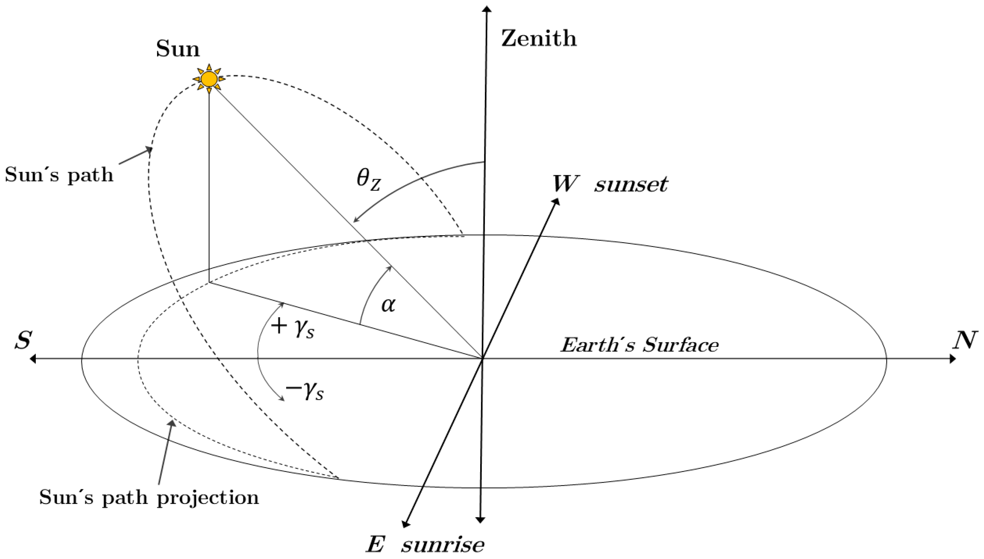
As shown in Figure 2, the zenith (θz) is the angle formed by the normal vector and the line joining the observer and the sun position and varies from 0° to 90°. The solar elevation ( α s ) is defined as the sun’s angular height above the horizon of the observer; this angle also varies between 0° and 90°, and it is also defined as the complement of the zenith angle. The solar azimuth ( γ s ) is the angle formed at the local zenith between the observer’s meridian plane and the plane passing through the zenith and the sun. It is measured to the east positively and west negatively and thus varies between 0° and 180°.
The zenith angle (θz) is obtained from Equation (2):
θ z = cos 1 ( sin δ sin φ + cos δ cos φ c o s ω )
The solar elevation ( α s ), as a complement of θz, is obtained in Equation (3):
α s = 90 θ z
Finally, the solar azimuth angle is obtained by Equation (4):
ϒ s = sin 1 cos δ s i n ω s i n θ z
The second solar position algorithm used was proposed by I. Reda [28], also known as the Solar Positioning Algorithm of the National Renewable Energy Laboratory (NREL’s SPA). The elevation angle (eSPA) and azimuth (azSPA) are defined in Equation (5) and Equation (6), respectively:
  e S P A = arcsin ( sin δ t sin φ + cos δ t cos φ c o s   ω )
a z S P A   = arctan 2 cos ω   cos ω s i n   φ t a n δ t   cos φ        
where δt is the topocentric declination angle, and ω′ is the topocentric hour angle.
D&B is an algorithm based on a series of geometric approximations, such as assuming a circular translation of the Earth around the sun to define the declination throughout the year, considering the length of the year as 365 days and determining the rotation time of the Earth during the year, simplifying the coordinates to spherical ones, and considering the propagation of errors derived from the two previous approximations. However, the SPA algorithm considers several factors, such as the true obliquity of the ecliptic, the aberration correction, the apparent solar longitude, the apparent sidereal time in Greenwich at a given time, and the geocentric solar declination. Thanks to these considerations, a much more accurate calculation of the local hour angle, the zenith angle, and the topocentric azimuthal angle, as well as the angle of incidence on a surface oriented in any direction, is obtained.

2.1.2. Solar Tracking Control System Configuration

The open-loop control system (red frame) consists of a code integrated into the user interface calculating the solar vector angles (Figure 3). For this work, the previously mentioned algorithms were used (Duffie & Beckham and SPA). These codes obtain elevation and azimuth angles ( A z , E l e v a n g l e s ), which are sent to the actuators of the tracking system axes to track the apparent sun’s position during the day. Each actuator receives a PWM signal from the principal controller to move the solar tracking structure. The angular position of each axis is obtained through two transducers (incremental encoders) coupled to azimuth and elevation movement mechanisms in the transmission of the tracking structure.
In the Hermosillo Solar Platform, an open-loop control configuration is used; there is no verification of the real position of the sun. Using a closed-loop configuration (Figure 2), the real position of the sun is continuously detected by a vision device. This device consists of a USB webcam model SVPRO 1080P with manual focus and a CMOS 2710 sensor that allows you to obtain sharp images with a field of view of up to 64°. The webcam has a 30 mm varifocal lens to which polarizing filters of neutral density are attached. These filters allow for regulating the amount of incident light on the sensor and thus control the aperture and exposure on the camera to display the image of the sun. In addition, this element simultaneously compares that position with a fixed reference to determine the sun’s displacement. This displacement, in turn, generates an error signal ( A z , E l e v c o r r .   a n g l e s ) that is fed back to the control system to make the position of the tracker normally coincide with the real position of the sun. Finally, the closed-loop process allows the FRESNEL concentrator solar tracker to contain the drift that has been presented over time, thereby correcting the objective position of the concentrated solar radiation projection on the target in the focal zone.
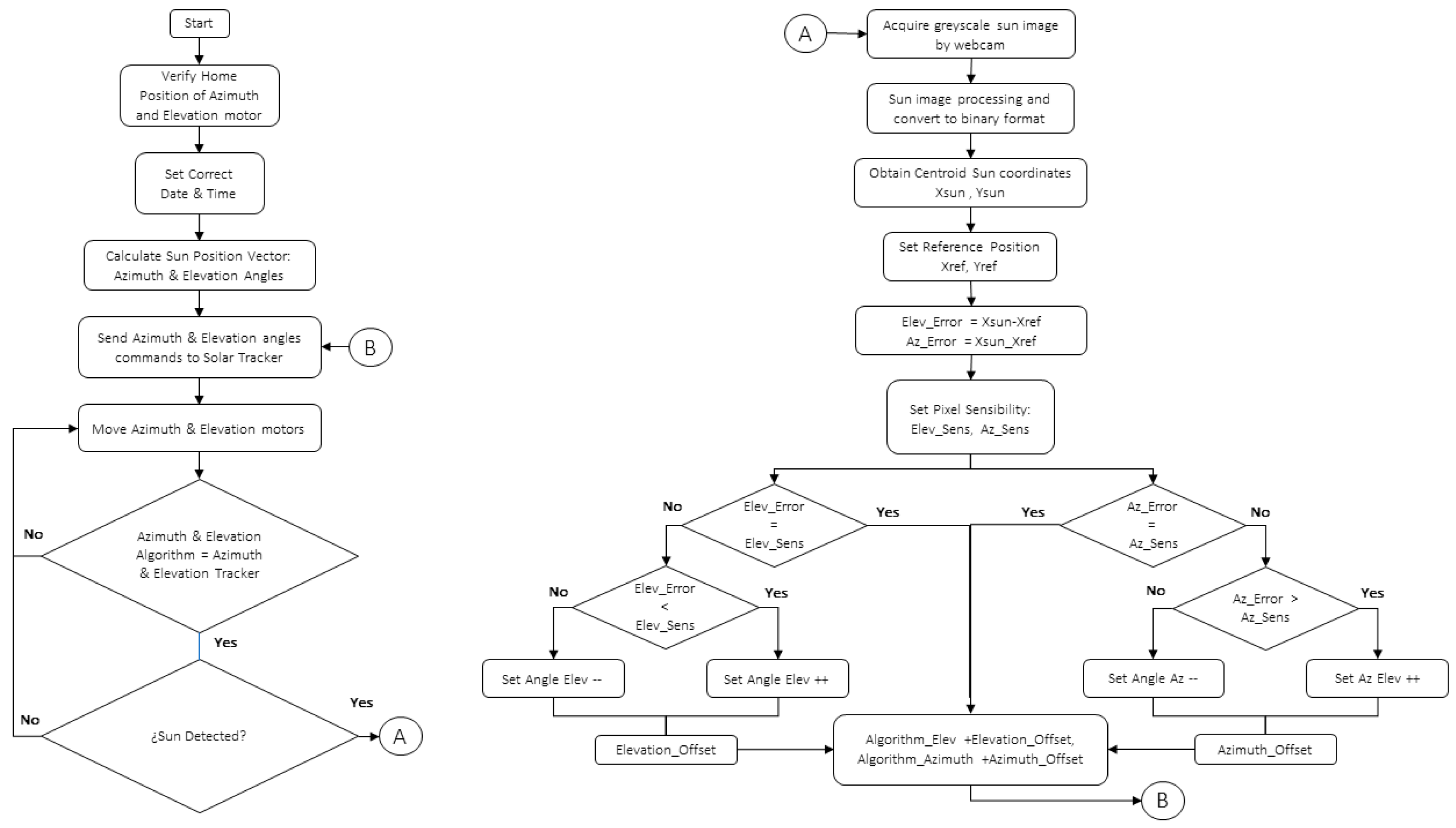
Figure 4 shows the flowchart representing the closed-loop methodology used here, which has an optical feedback system, Webcam1, allowing us to observe the sun’s position in real time. Using an image processing algorithm, an XY coordinate is established as a fixed reference in the camera image, which is compared with the dynamic reference given by the centroid of the image formed by the sun and the error generated by the deviation between the centroid current position and the fixed reference point is obtained. With this error, a feedback signal providing correction angles is obtained, which are added to those already calculated by the solar position algorithm to contain displacement on the tracking device.

2.1.3. Experimental Design

The FRESNEL concentration system requires keeping the plane formed by the first optical element perpendicular to the solar radiation incidence vector. In other words, the position of the optical axis of the concentrator should always be towards the sun position throughout the day. For the experimental design of the FRESNEL concentrator (Figure 5), the first vision device (Webcam1) is used to monitor the real-time position of the sun. Webcam1 was located on the structure of the solar tracker and positioned perpendicular to the plane formed by the primary optical element (POE); that is, it was placed in a position parallel to the concentrator optical axis to maintain the normal vision vector at the sun’s position. The use of the POE is to focus the mirror’s concentrated radiation on the Lambertian target located in the focal point (1.5 m) of the system, which furthers the location of high-efficiency photovoltaic cell characterization systems. The second viewing device, Webcam2, placed on the optical axis, allowed the projection of sunspots onto the Lambertian target to be observed during 4 h of experimentation: two hours before and two hours after solar noon, close to the winter solstice, which implied the maximum inclination for the elevation mechanism. This was the critical point for the tracking system.
As shown in Figure 5, each vision element configuration allowed the evaluation of angular displacement through the trajectory marked by each of the centroids calculated in real time. Webcam1 plots the centroid trajectory for the sun image, and Webcam2 obtains the centroid trajectory given by the sunspot image projected on the receiver.

2.1.4. Real-Time Digital Image Processing

With Webcam1 and Webcam2 in their respective positions on the FRESNEL solar concentrator, the images are acquired in 8-bit and grayscale format for individual digital processing. For image processing, the Vision Assistant 2019 software from National Instruments (National Instruments CORP., Texas, USA) is used, which allows configuring a script with different blocks of image processing algorithms.

Image Acquisition

First, the sun image and reflected spot in grayscale are treated as a matrix of MXN elements. Each element ( P i x m , n ) of the digitalized image had a value corresponding to the image point brightness [29]. Both images can be represented as a bidimensional matrix, as shown in Equation (7):
I m = P i x 1,1 P i x 1 , n P i x m , 1 P i x m , n
Images were obtained at intervals of 1 s. The range of gray levels for each image is from 0 to 255, and a matrix element is represented by P i x m , n 0 255 .

Image Mask Function

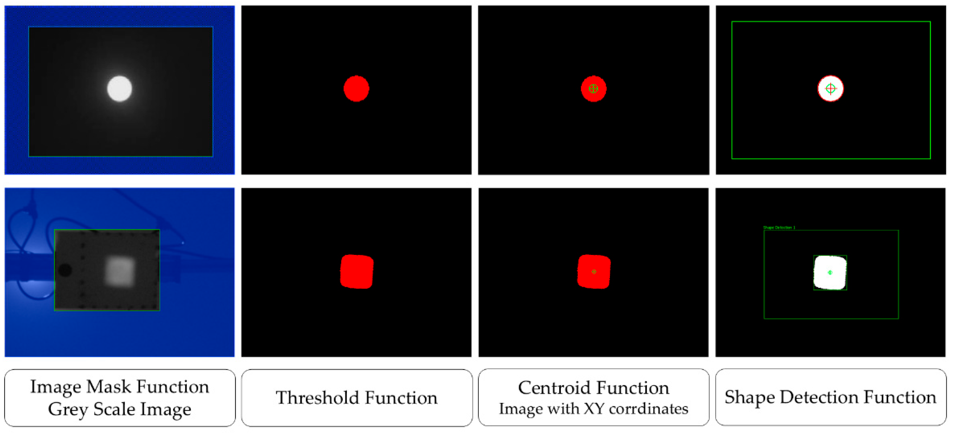
After obtaining the grayscale image, we built an “image mask” to set a region of interest (ROI) and delete brightness produced by other elements that could affect the centroid calculation. An “image mask options” sets all pixels outside an image containing values of 1 and 0.
For the image of the sun, an arbitrary zone of interest is configured due to the distance and field of view of Webcam1 with respect to the sun. For the projected image of the sunspot, the area of interest is set equal to the area of the receiver to eliminate noise produced by the brightness of the elements close to it (see Figure 6).

Threshold Function

In the third stage, the image was set with a threshold function generating a binary image from the grayscale image and was defined by a threshold value ( T h ) [29]. For the threshold function, the default value is red. To each pixel on the image, a value was assigned depending on “ T h ”, for P v a l T h , the pixel intensity is 0, and for P v a l T h , the intensity of the pixel is 255. This is represented in Equation (8):
I m b i n = 0       i f       P v a l T h 0       i f       P v a l T h
For a binary image, P v a l = 0 was equal to 0 (black pixel with no energy), and P v a l = 255 was equal to 1 (white pixel with energy).

Centroid Function

After the original image was converted to a binary image, an image contour was obtained, and the centroid function was applied to calculate pixel coordinates X c and Y c , corresponding to the image energy center. This function is represented in Equation (9):
X c = X = 1 X = n X P v a l / X = 1 X = n P v a l , Y c = Y = 1 Y = n Y P v a l / Y = 1 Y = n P v a l
The program allowed for saving each one of the X c and Y c centroid coordinates, generating a history that permitted us to visualize the displacement trajectory from the initial point at the beginning of the experiment to the final point at the end of the experiment in real time.

Lookup Table Function

With the lookup table function, we can improve the contrast and brightness of each image after applying the threshold function. With the option “Equalize” in this block, we can increase the intensity of pixels through a given threshold range. Pixels are represented by the color white for those with a binary value of 1 and black pixels with a value of 0. This step provides pixel intensity information in a linear histogram.

Shape Detection Function

Finally, for the detection of the edge of the sun image and the sunspot, the shape detection function was used. The algorithm of this step detects object curves based on the assumption that each object in the image or the object background consists of uniform pixel values. Within the algorithm, there is an “Edge Threshold” subfunction that allows for specifying the minimum contrast that an edge pixel must have to be considered part of the detected curve. This value is set equal to the value set by the threshold function previously configured in the image analysis.

3. Results

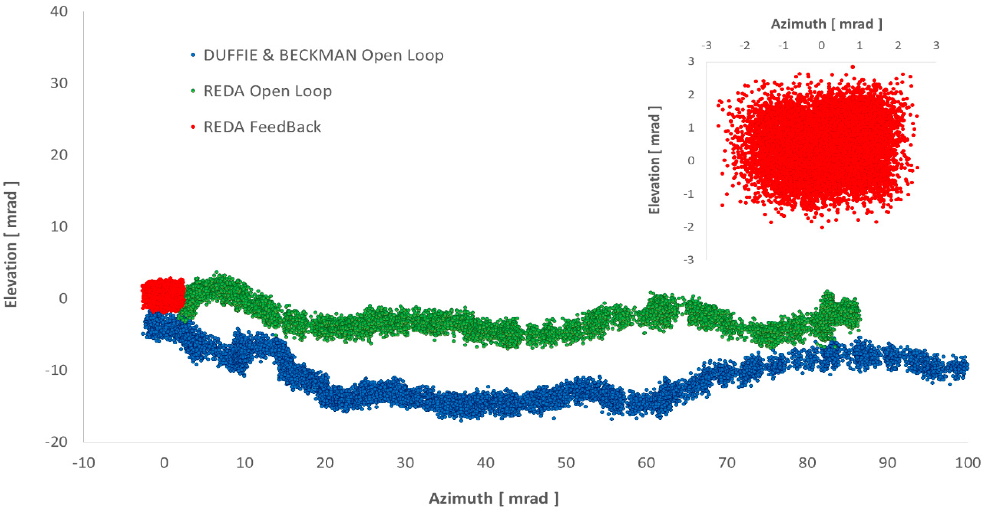
Comparative analysis between Duffie & Beckman (D&B) and SPA algorithms considered solar vector azimuth and elevation angles calculated by each algorithm. The open-loop strategy was used for sun tracking on 26 and 27 September 2022, using DB and SPA algorithms, respectively. The D&B algorithm in open-loop had a significant displacement of 100 mrad in azimuth angle and 15 mrad in elevation angle. These deviations corresponded to 5.71° in the horizontal direction and 0.84° in the vertical direction. Sunspot displacement on the Lambertian target at the starting point was 0.1003 m in the X coordinate (azimuth) and 0.014 m in the Y coordinate (elevation). The SPA algorithm in open-loop exhibited a displacement of 87 mrad and 10 mrad for azimuth and elevation angles, respectively. With SPA, the last point of the trajectory had a total displacement of 87 mrad in azimuth angle and 13 mrad in elevation angle. Regardless of the algorithm, using an open-loop control strategy for solar tracking represents a significant displacement of incident concentration spot on target.
On 20 October 2022, containment of displacement was analyzed using the closed-loop strategy and SPA algorithm. Each webcam registered an image per second in a period of 3.5 h, from 10:00 am to 13.30 pm. Figure 7 shows the trajectory marked by the sun images of centroids. Displacement decreased by 95% using SPA in closed-loop for azimuth angle and 45% for elevation angle, compared to the SPA algorithm in open-loop. Containment of displacement in a closed loop allowed an oscillation of ±2.5 mrad on both azimuth and elevation angles.
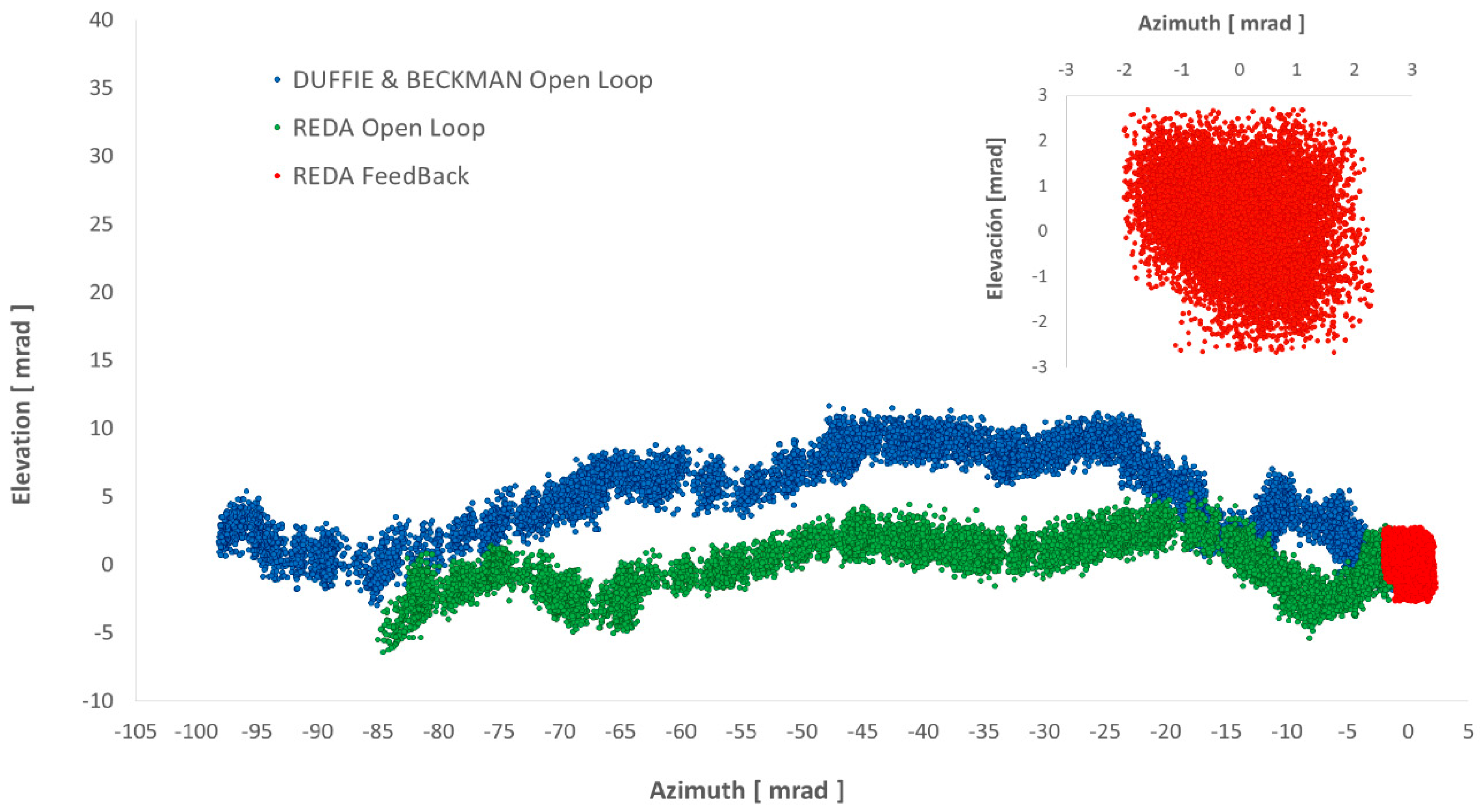
Figure 8 shows angular displacements of the concentration spot projection of FRESNEL on the Lambertian target. Drift containment with SPA in a closed loop allowed for the concentration spot projection to be on target with an oscillation of ±2 mrad over the horizontal direction (azimuth) and ±2.5 mrad in the vertical direction (elevation).
The closed-loop control strategy enabled the spot to be maintained in an adequate range in the Lambertian target, keeping incident radiation constant in the zone of interest. Table 2 depicts sunspot displacements registered by Webcam2; that is, the sunspot projection over the Lambertian target of FRESNEL concentrator for both algorithms with the open-loop and for SPA with closed-loop strategy. According to the results, the closed-loop control strategy with the SPA algorithm decreased displacement in elevation and azimuth axes compared to displacements obtained using the open-loop control strategy. With the closed-loop strategy, the spot oscillated in an area of ±0.0043 m over the horizontal direction (azimuth) and approximately ±0.0054 m over the vertical direction (elevation).
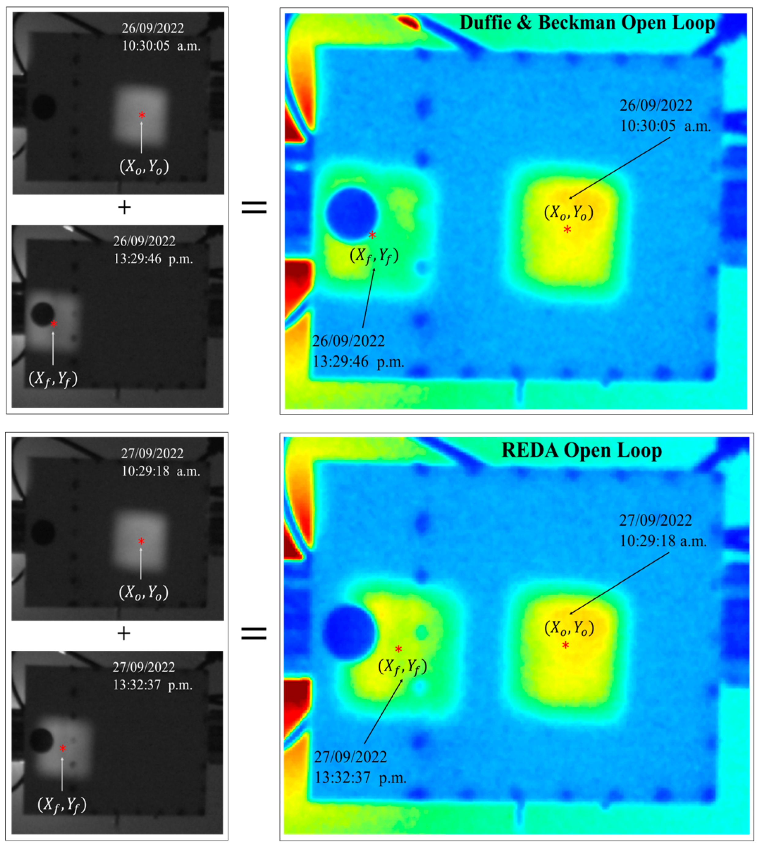
Figure 9 shows the reflected image by FRESNEL POE mirrors bank; it depicts the behavior displacement of reflected images on the Lambertian target. Greyscale images show separately the sunspot from the starting point of reference ( X O , Y O ) to the ending point ( X f , Y f ) . Greyscale images were added and converted into a colormap to show total displacement in two axes during the evaluation period for open-loop algorithms. D&B trajectory (up) shows a higher spot displacement in both directions, 0.1003 m in the horizontal direction (azimuth) and 0.0147 m in the vertical direction (elevation). On the other hand, for the SPA algorithm (down), the trajectory presents a minor displacement of 0.0879 m in the horizontal direction (azimuth) and 0.0127 m over the vertical direction (elevation), compared to the D&B algorithm.
The main similarity between the D&B algorithm and SPA in open-loop is the spot deviation position from the reference point in the zone of interest. The aim was to keep the incident radiative flux over the cell constant during the experimentation period. Closed-loop control with the SPA algorithm and web camera feedback allowed for a decrease in displacement at 96% in azimuth angle and 66% in elevation angle. The highest displacement for both angles was registered when using the D&B algorithm with an open-loop strategy. With closed-loop strategy and SPA configuration, a containment of displacement of ±0.00215 m in the azimuth direction and ±0.0027 m in the elevation direction was obtained (Figure 10).

4. Conclusions

The closed-loop control strategy proposed in this work successfully contained sunspot drift projected on the Lambertian target for the FRESNEL tracking system. Drift containment presented an improvement of approximately 96% in azimuth angle and approximately 66% in elevation angle with respect to displacement when applying the open-loop solar tracking control strategy. Thus, this solar tracking control system makes it possible to track the sun’s apparent position with such precision that it is certain that the sunspot projection will remain fixed within a permissible range over the area of interest in the Lambertian target. With the system in a closed-loop configuration, displacement containment obtained was in a range of approximately ±0.00215 m in azimuth direction and ±0.0027 m in elevation direction.
The closed-loop control strategy proposed in this work allows for the FRESNEL concentrator to have accurate solar tracking in addition to controlling the displacement of the sunspot projection on the receiver. However, there may be disturbances that could compromise the optimal performance of the control output of the tracking system. The system can perform optimally on completely clear days; cloudy sky conditions can affect the calculation of the centroid of the sun image. This is because the exposure and lens aperture conditions are constant, so it would directly affect the amount of light that passes through the sensor. Another disadvantage is that the image processing is performed using specialized software, which requires a license and a high computational resource, which would lead to an increase in the cost of implementing the system.
Webcams can operate outdoors if they are protected from rain, humidity, and dust conditions. However, the lens and the polarized filters are constantly exposed to UV radiation, which wears out the quality of the filters and materials, compromising the quality of the images acquired, so periodic maintenance of the components is necessary.

Author Contributions

H.G.-C.: Conceptualization, methodology, formal analysis, and writing—original draft; C.A.P.-R.: supervision, methodology, and resources; Y.R.G.-L.: conceptualization, writing—original draft, methodology, and writing—review and editing; R.C.-V.: data curation and visualization; R.A.P.-E.: resources and visualization; R.G.-G.: resources and validation; C.A.E.-G.: supervision. All authors have read and agreed to the published version of the manuscript.

Funding

The authors are grateful for the financial support granted by UNAM-PAPIIT IG101422.

Data Availability Statement

The original contributions presented in this study are included in the article. Further inquiries can be directed to the corresponding author.

Acknowledgments

Author Hector Gonzalez-Camarillo appreciates the scholarship granted for completion of a Ph.D. by CONACyT-Mexico.

Conflicts of Interest

The authors declare no conflicts of interest.

Nomenclature

PVPhotovoltaic
CPVConcentration photovoltaic
CNNConvolutional Neural Networks
HCPVHigh-concentration photovoltaic
FRESNELFocusing Retractile heliostat as Evaluator System for Non-imaging concentrated solar Electric generators
SAPOE Semicircular arrays of the primary optical element
POEPrimary optical element
SEOSecond optical element
δSolar declination
wHour angle, °
NJulian day
θ z Zenith angle, °
γ s Azimuth angle, °
α s Elevation angle, °
φ Latitude
LlocLocal Longitude
LstdStandard Longitude
π Pi constant
NRELNational Renewable Energy Laboratory
SPASolar position algorithm
eSPAElevation angle SPA, °
azSPAAzimuth angle SPA, °
δ t Topocentric declination angle, °
ω Topocentric hour angle, °
P i x m , n Pixel element in matrix of an image
ImBidirectional matrix of an image
T h Threshold value
P v a l Pixel value of an image, 0-255
I m b i n Binary image in threshold function
X c Coordinate X of centroid image
Y c Coordinate Y of a centroid image
D&BDuffie & Beckman
X o Reference pixel in X
Y o Reference pixel in Y
X f Final reference pixel in X
Y f Final reference pixel in Y

References

  1. Carballo, J.A.; Bonilla, J.; Berenguel, M.; Fernández-Reche, J.; García, G. New approach for solar tracking systems based on computer vision, low cost hardware and deep learning. Renew. Energy 2019, 133, 1158–1166. [Google Scholar] [CrossRef]
  2. El Jaouhari, Z.; Zaz, Y.; Moughyt, S.; El Kadmiri, O.; El Kadmiri, Z. Dual-axis solar tracker design based on a digital hemispherical imager. J. Sol. Energy Eng. 2019, 141, 011001. [Google Scholar] [CrossRef]
  3. Nsengiyumva, W. Che International Renewable Energy Agency. Available online: https://www.irena.org/data (accessed on 27 February 2025).
  4. Cancro, C.; Palladino, V.; Borriello, A.; Romano, A.; Mongibello, L. Design of a novel hybrid concentrated photovoltaic-thermal system equipped with energy storage, optimized for use in residential contexts. Solar 2024, 4, 526–554. [Google Scholar] [CrossRef]
  5. Tilli, F. GSE/Giosuè Maugeri—RSE, National Survey Report of PV Power Applications in Italy. 2018. Available online: https://iea-pvps.org/wp-content/uploads/2020/01/NSR_Italy_2018.pdf (accessed on 27 February 2025).
  6. Nsengiyumva, W.; Chen, S.G.; Hu, L.; Chen, X. Recent advancements and challenges in Solar Tracking Systems (STS): A review. Renew. Sust. Energ. Rev. 2018, 81, 250–279. [Google Scholar] [CrossRef]
  7. Sidek, M.H.M.; Azis, N.; Hasan, W.Z.; Ab Kadir, M.Z.A.; Shafie, S.; Radzi, M.A.A. Automated positioning dual-axis solar tracking system with precision elevation and azimuth angle control. Energy 2017, 124, 160–170. [Google Scholar] [CrossRef]
  8. Foundation, C.; Lee, S.K.; Han, Y.H.; Lee, W.; Ryu, W. Foundation, Passive Solar Tracking System to Enhance Solar Cell Output. US20140238488A1 17 January 2017. [Google Scholar]
  9. Melo, A.G.; Filho, D.O.; De Oliveira Júnior, M.M.; Zolnier, S.; Ribeiro, A. Development of a closed and open loop solar tracker technology Acta Sci. Technol. 2017, 39, 177–183. [Google Scholar] [CrossRef]
  10. Chowdhury, M.E.H.; Khandakar, A.; Hossain, B.; Abouhasera, R. A low-cost closed-loop solar tracking system based on the sun position algorithm. J. Sens. 2019, 2019, 3681031. [Google Scholar] [CrossRef]
  11. González-Camarillo, H.; Calleja, R.; Pérez-Enciso, R.A.; Pérez-Rábago, C.; Estrada-Gasca, C.A. Corrección de la deriva en sistemas de seguimiento solar a través de control de lazo cerrado. In Proceedings of the XVII Congreso Ibérico y XIII Congreso Iberoamericano de Energía Solar, Online, 3–5 November 2020; pp. 601–609. [Google Scholar]
  12. Azizi, K.; Ghaffari, A. Design and manufacturing of a high-precision sun tracking system based on image processing. Int. J. Photoenergy 2013, 2013, 754549. [Google Scholar] [CrossRef]
  13. Pérez-Enciso, R.; Brito-Bazan, E.; Pérez-Rábago, C.A.; Arancibia-Bulnes, C.A.; Riveros-Rosas, D.; Estrada, C.A. Correction of the concentrated sunlight spot’s drift of the IER-UNAM’s solar furnace. Appl. Therm. Eng. 2015, 75, 1187–1191. [Google Scholar] [CrossRef]
  14. Rubio, F.R.; Ortega, M.G.; Gordillo, F.; López-Martínez, M. Application of new control strategy for sun tracking. Energ. Convers. Manag. 2007, 48, 2174–2184. [Google Scholar] [CrossRef]
  15. Oh, S.J.; Lee, Y.J.; Chen, J.K.; Kim, Y.M.; Lim, S.H.; Chun, W. Development of an embedded solar tracker for the enhancement of solar energy utilization. Int. J. Energy Res. 2012, 36, 249–258. [Google Scholar] [CrossRef]
  16. Zhang, J.; Yin, Z.; Jin, P. Error analysis and auto correction of hybrid solar tracking system using photo sensors and orientation algorithm. Energy 2019, 182, 585–593. [Google Scholar] [CrossRef]
  17. Adrian, W.Y.W.; Durairajah, V.; Gobee, S. Autonomous dual axis solar tracking system using optical sensor and sun trajectory, in Lecture Notes in Electrical Engineering. In Proceedings of the 8th International Conference on Robotic, Vision, Signal Processing & Power Applications; Springer: Singapore, 2014; pp. 507–520. [Google Scholar] [CrossRef]
  18. Kumar, V.S.S. Automatic dual axis sun tracking system using LDR Sensor. Int. J. Curr. Eng. Technol. 2011, 4, 3214–3217. [Google Scholar] [CrossRef]
  19. Mishra, J.; Thakur, R.; Deep, A. Arduino based dual axis smart solar tracker. Int. J. Adv. Eng. Manag. Sci. 2017, 3, 532–535. [Google Scholar] [CrossRef]
  20. Gabe, I.J.; Bühler, A.; Chesini, D.; Frosi, F. Design and implementation of a low-cost dual-axes autonomous solar tracker. In Proceedings of the 8th International Symposium on Power Electronics for Distributed Generation System, Florianopolis, Brazil, 17–20 April 2017. [Google Scholar]
  21. Jamroen, C.; Komkum, P.; Kohsri, S.; Himananto, W.; Panupintu, S.; Unkat, S. A low-cost dual-axis solar tracking system based on digital logic design: Design and implementation. Sustain. Energy Technolo. Assess. 2020, 37, 1000618. [Google Scholar] [CrossRef]
  22. Ahmed, R.; Oh, S.J.; Mehmood, M.U.; Kim, Y.; Jeon, G.; Joo Han, H.; Hoon Lim, S. Computer vision and photosensor based hybrid control strategy for a two-axis solar tracker—Daylighting application. Sol. Energy 2021, 224, 175–183. [Google Scholar] [CrossRef]
  23. Garcia-Gil, G.; Ramirez, J.M. Fish-eye camera and image processing for commanding a solar tracker. Heliyon 2019, 5, e01398. [Google Scholar] [CrossRef]
  24. Abdollahpour, M.; Golzarian, M.R.; Rohani, A.; Abootorabi Zarchi, H. Development of a machine vision dual-axis solar tracking system. Sol. Energy 2018, 169, 136–143. [Google Scholar] [CrossRef]
  25. Fuentes-Morales, R.F.; Diaz-Ponce, A.; Peña-Cruz, M.I.; Rodrigo, P.M.; Valentín-Coronado, L.M.; Martell-Chavez, F.; Pineda-Arellano, C.A. Control algorithms applied to active solar tracking systems: A review. Sol. Energy 2020, 212, 203–219. [Google Scholar] [CrossRef]
  26. Garrido, R.; Díaz, A. Cascade closed-loop control of solar trackers applied to HCPV systems. Renew. Energy 2016, 97, 689–696. [Google Scholar] [CrossRef]
  27. Duffie, J.A.; Beckman, W.A. Solar Engineering of Thermal Processes; Wiley: Hoboken, NJ, USA, 1980; Available online: http://eu.wiley.com/WileyCDA/WileyTitle/productCd-0470873663.html (accessed on 5 January 2013).
  28. Reda, I.; Andreas, A. Solar position algorithm for solar radiation applications. Sol. Energy 2004, 76, 577–589. [Google Scholar] [CrossRef]
  29. Posada-Gómez, R.; Sandoval-González, O.O.; Martínez Sibaja, A.; Portillo-Rodríguez, O.; Alor-Hernández, G. Digital Image Processing Using LabView; InTech: Vienna, Austria, 2011. [Google Scholar] [CrossRef]
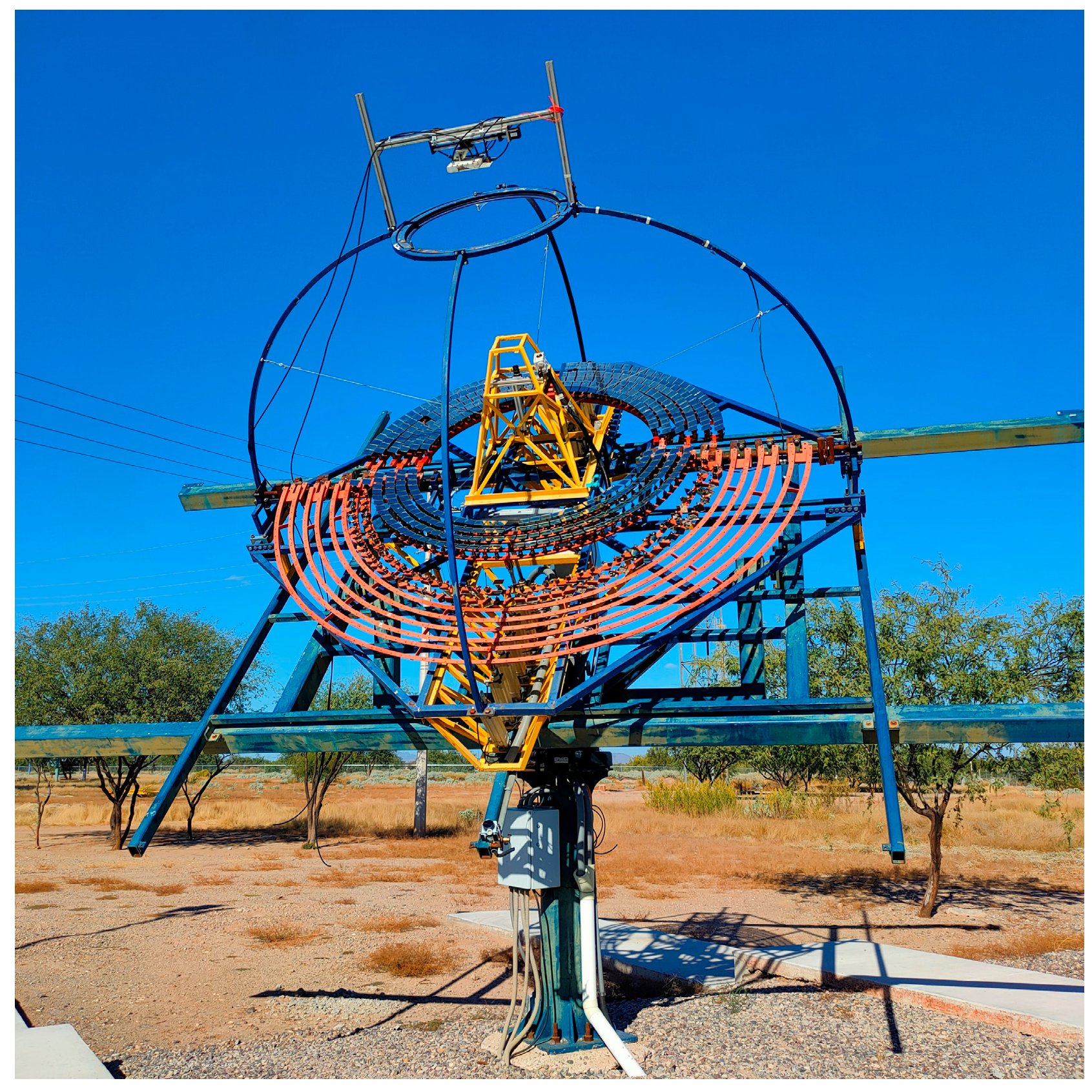
Figure 1. Solar FRESNEL concentrator installed at the Hermosillo solar platform in Sonora, Mexico.
Processes 13 00944 g001
Figure 2. Apparent sun path and solar angles with respect to Earth’s surface.
Processes 13 00944 g002
Figure 3. Open and closed-loop control systems diagram.
Processes 13 00944 g003
Figure 4. Closed-loop control strategy flowchart.
Processes 13 00944 g004
Figure 5. Experimental scheme for feedback in FRESNEL concentrator.
Processes 13 00944 g005
Figure 6. Image processing to obtain sun image centroid and reflected spot.
Processes 13 00944 g006
Figure 7. Sun image displacement observed from Webcam1 in FRESNEL concentrator.
Processes 13 00944 g007
Figure 8. Displacement of sunspot centroid reflected in Lambertian target in FRESNEL concentrator (Webcam2).
Processes 13 00944 g008
Figure 9. Sunspot centroid displacement reflected in the Lambertian target of FRESNEL concentrator (Webcam2) for open-loop algorithm.
Processes 13 00944 g009
Figure 10. Solar spot centroid containment of displacement reflected in the Lambertian target.
Processes 13 00944 g010
Table 1. Number of mirrors and distance sections of the semicircular arrangements of the POE.
ArraySection (m)No. of MirrorsArraySection (m)of Mirrors
00.554081.07116
10.606491.14124
20.6672101.21132
30.7280111.29140
40.7984121.37148
50.8692131.45156
60.93100141.53164
71.00108151.61168
Table 2. Comparison of sunspot projection displacement on the Lambertian target in FRESNEL concentrator.
Solar Axis TrackerDisplacement
[mrad]
Displacement
[°]
Displacement
[m]
(a) Duffie & Beckman algorithm in open-loop
Azimuth 1005.710.1003
Elevation 150.840.0147
(b) SPA algorithm in open-loop
Azimuth8750.0879
Elevation 130.720.0127
(c) SPA algorithm in closed-loop
Azimuth40.250.0043
Elevation 50.310.0054
Disclaimer/Publisher’s Note: The statements, opinions and data contained in all publications are solely those of the individual author(s) and contributor(s) and not of MDPI and/or the editor(s). MDPI and/or the editor(s) disclaim responsibility for any injury to people or property resulting from any ideas, methods, instructions or products referred to in the content.