Shear Rate Coat-Hanger Die Using Casson Viscosity Model


Abstract
:1. Introduction
2. Mathematical Modeling
2.1. General
- ▪
- Steady state flow;
- ▪
- Isothermal flow;
- ▪
- Hydrodynamically fully developed flow;
- ▪
- Incompressible fluid;
- ▪
- No external forces (e.g., the effect of gravity is neglected);
- ▪
- No slip boundary condition;
- ▪
- Uniform shear rate at the walls of the manifold and slit region.
- ▪
- The radius of the manifold at the edge is equal to the half-height of the slit .
2.2. Casson Model-Based Design Equations
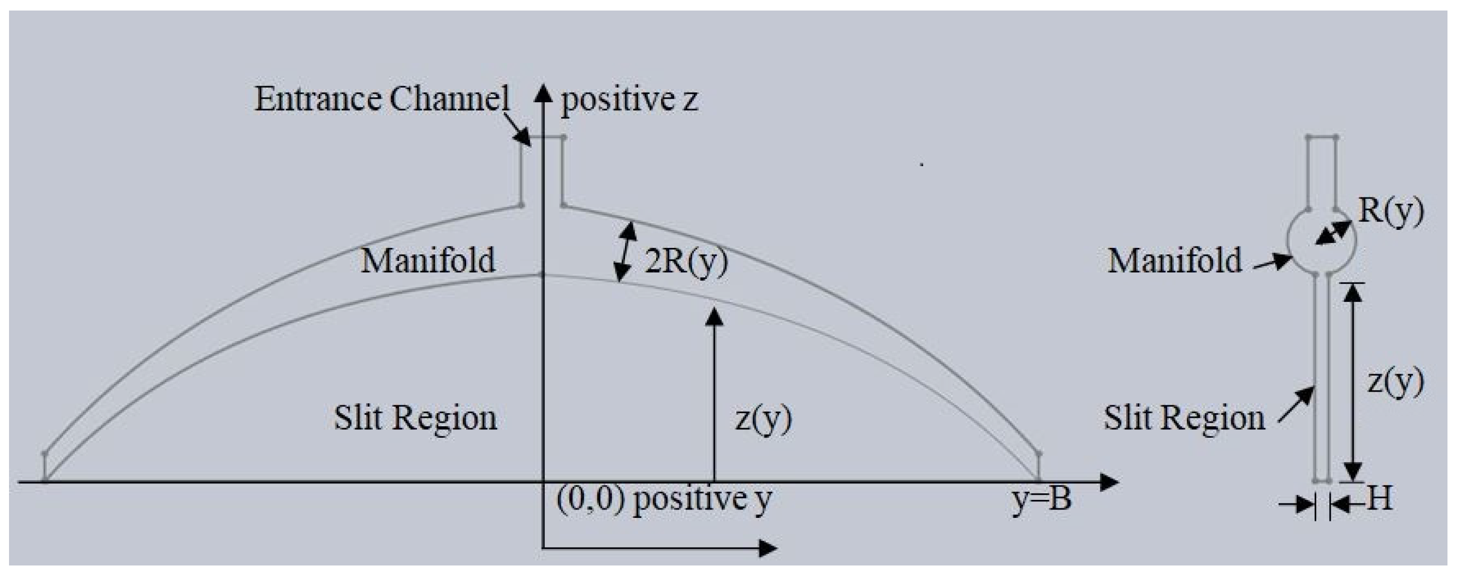
2.2.1. Manifold Region
2.2.2. Slit Region
2.2.3. Computation of the Design Equations
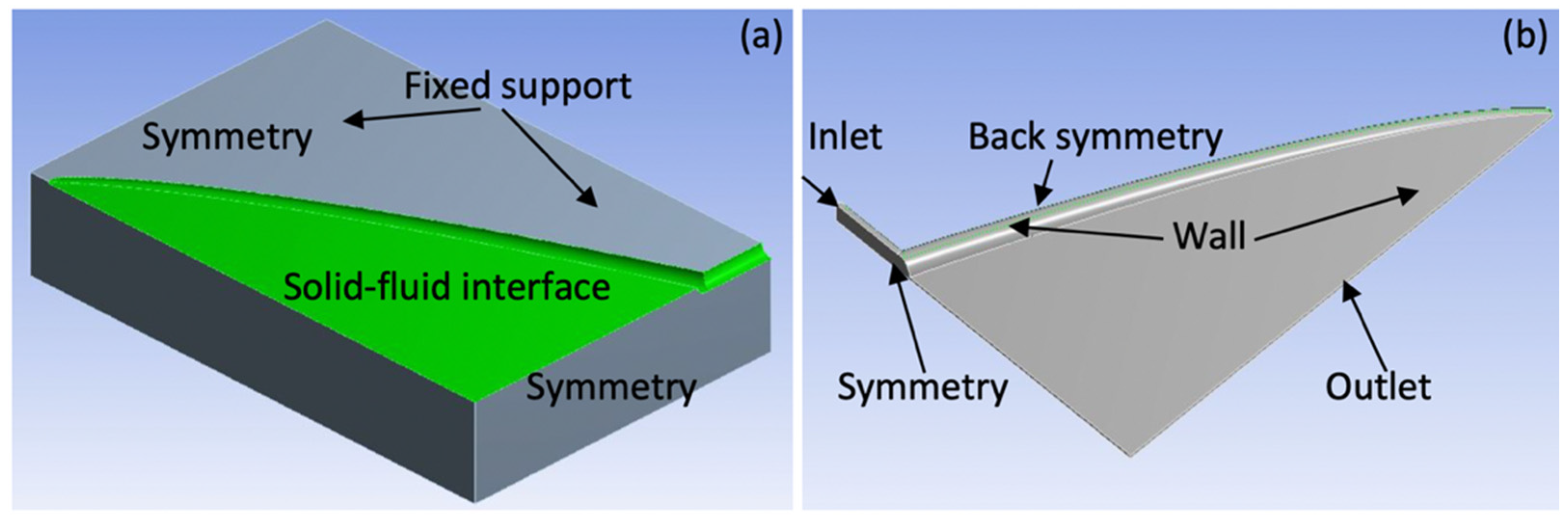
3. Computational Model
- The polymer melt is a incompressible non-Newtonian fluid;
- The polymer flow is assumed to be isothermal, laminar, and fully developed;
- There is a no-slip condition between die wall and polymer melt.
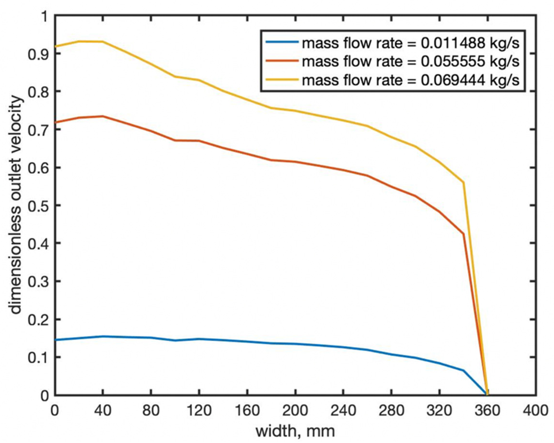
4. Discussion
5. Conclusions
Author Contributions
Funding
Acknowledgments
Conflicts of Interest
References
- Wu, T.; Jiang, B.; Xu, S.; Huang, N. Three-dimensional nonisothermal simulation of a coat hanger die. J. Appl. Polym. Sci. 2006, 101, 2911–2918. [Google Scholar] [CrossRef]
- Matsubara, Y. Geometry design of a coat-hanger die with uniform flow rate and residence time across the die width. Polym. Eng. Sci. 1979, 19, 169–172. [Google Scholar] [CrossRef]
- Chung, C.I. Die Designs. In Extrusion of Polymers: Theory & Practice, 2nd ed.; Hanser Verlag: Munich, Germany, 2019; pp. 373–412. [Google Scholar]
- Kopplmayr, T.; Aigner, M.; Miethlinger, J. A Comparative Study of Viscous Flow in Slit-Exit Cross Section Dies Using Network Analysis. J. Plast. Technol. 2012, 8, 54–73. [Google Scholar]
- Vlachopoulos, J.; Polychronopoulos, N.; Tanifuji, S.; Müller, J.P. Flat Film and Sheet Dies. In Design of Extrusion Forming Tools, 1st ed.; Carneiro, O., Nobrega, J.M., Eds.; Smithers Rapra: London, UK, 2012; pp. 113–140. [Google Scholar]
- Huang, Y.; Gentle, C.R.; Hull, J.B. A comprehensive 3-D analysis of polymer melt flow in slit extrusion dies. Adv. Polym. Technol. 2004, 23, 111–124. [Google Scholar] [CrossRef]
- Meng, K.; Wang, X.; Chen, Q. Fluid flow in coat-hanger die of melt blowing process: Comparison of numerical simulations and experimental measurements. Text. Res. J. 2011, 81, 1686–1693. [Google Scholar] [CrossRef]
- Lee, P.C.; Dietsche, L.; Dooley, J.; Parashar, S. Improving Film Die Flow Uniformity Using Optimization Methods Coupled with Finite Element Computational Fluid Dynamics (CFD) Analysis. Int. Polym. Process. 2015, 30, 51–62. [Google Scholar] [CrossRef]
- Smith, D.E.; Wang, Q. Optimization-based design of polymer sheeting dies using generalized Newtonian fluid models. Polym. Eng. Sci. 2005, 45, 953–965. [Google Scholar] [CrossRef]
- Wang, Q.; Smith, D.E. Analysis of the fluid–structure interaction in the optimization-based design of polymer sheeting dies. J. Appl. Polym. Sci. 2006, 103, 3994–4004. [Google Scholar] [CrossRef]
- Winter, H.H.; Fritz, H.G. Design of dies for the extrusion of sheets and annular parisons: The distribution problem. Polym. Eng. Sci. 1986, 26, 543–553. [Google Scholar] [CrossRef]
- Casson, N. A Flow Equation for Pigment-Oil Suspensions of the Printing Ink Type. In Rheology of Disperse Systems; Mill, C.C., Ed.; Pergamon: New York, NY, USA, 1959. [Google Scholar]
- Mukhopadhyay, S. Casson fluid flow and heat transfer over a nonlinearly stretching surface. Chin. Phys. B 2013, 22, 074701. [Google Scholar] [CrossRef]
- Khan, M.I.; Waqas, M.; Hayat, T.; Alsaedi, A. A comparative study of Casson fluid with homogeneous-heterogeneous reactions. J. Colloid Interface Sci. 2017, 498, 85–90. [Google Scholar] [CrossRef] [PubMed]
- Michaelides, E.E.; Crowe, C.T.; Schwarzkopf, J.D. Fluid–Solid Flow in Ducts. In Multiphase Flow Handbook; Informa UK Limited: London, UK, 2016; pp. 357–454. [Google Scholar]
- Nandy, S.K. Analytical Solution of MHD Stagnation-Point Flow and Heat Transfer of Casson Fluid over a Stretching Sheet with Partial Slip. ISRN Thermodyn. 2013, 2013, 1–9. [Google Scholar] [CrossRef]
- Ullah, I.; Alkanhal, T.A.; Shafie, S.; Nisar, K.S.; Khan, I.; Makinde, O.D. MHD Slip Flow of Casson Fluid along a Nonlinear Permeable Stretching Cylinder Saturated in a Porous Medium with Chemical Reaction, Viscous Dissipation, and Heat Generation/Absorption. Symmetry 2019, 11, 531. [Google Scholar] [CrossRef] [Green Version]
- Lungu, M.; Petrovan, S.; Rusu, M.; Apetroaiei, A.; Lungu, A. Application of rheological models for the description of the flow characteristics of some polymer systems. Acta Polym. 1992, 43, 214–218. [Google Scholar] [CrossRef]
- Matveenko, V.N.; Kirsanov, E.A. Structural Viscosity and Structural Elasticity of Polymer Melts. Russ. J. Appl. Chem. 2018, 91, 839–865. [Google Scholar] [CrossRef]
- Hopmann, C.; Michaeli, W. Fundamental Equations for Simple Flows. In Extrusion Dies for Plastics and Rubber: Design and Engineering Computations, 4th ed.; Hanser Publications: Munich, Germany, 2016; pp. 49–82. [Google Scholar]
- Gurauskis, J.; Baudín, C.; Sanchez-Herencia, A. Tape casting of Y-TZP with low binder content. Ceram. Int. 2007, 33, 1099–1103. [Google Scholar] [CrossRef]


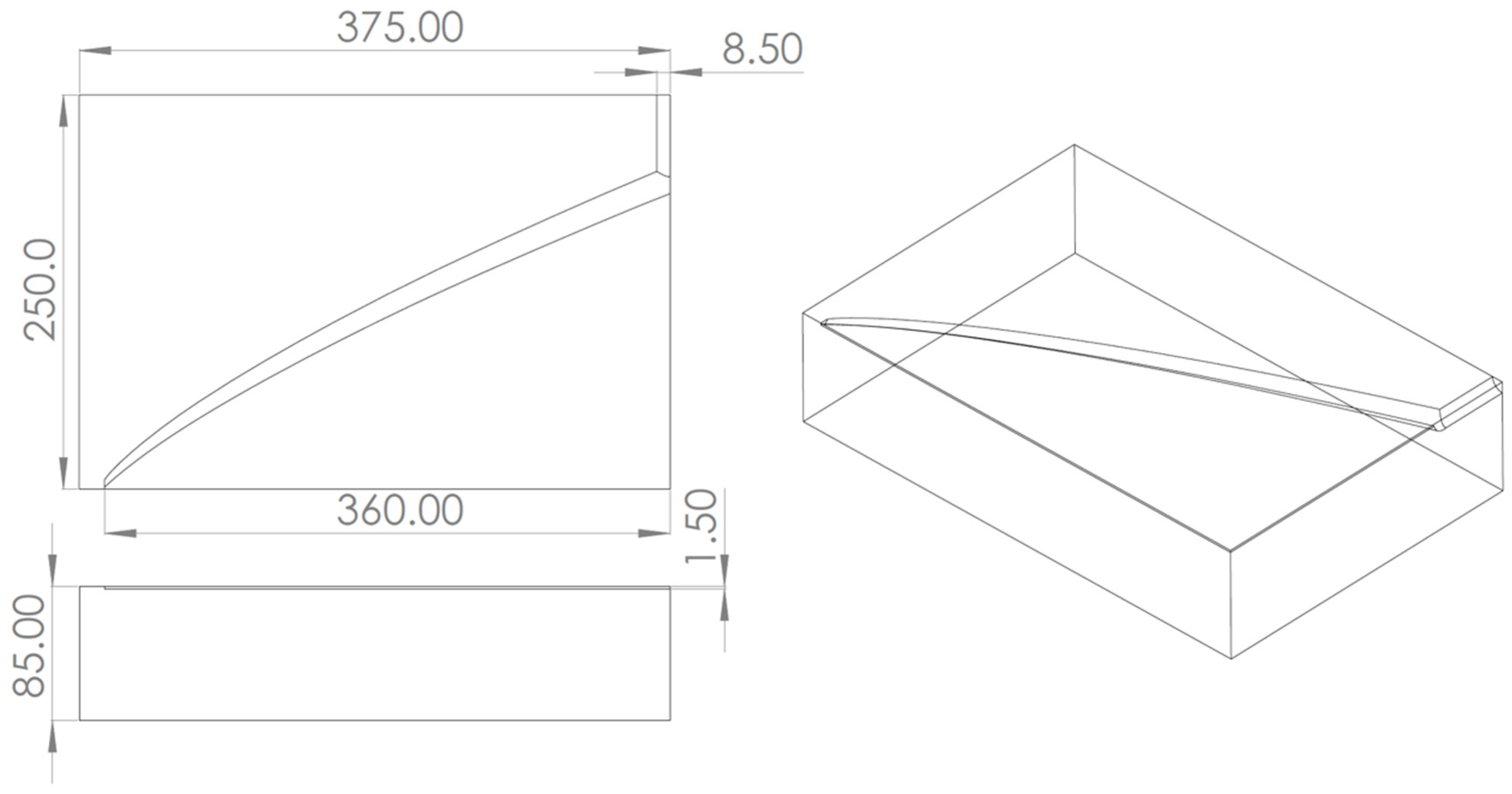
| Entrance Diameter, mm | Distance between Inlet and Outlet, mm | Thickness, mm | Width, mm | Height of the Gap, mm | Width of the Gap, mm |
|---|---|---|---|---|---|
| 20 | 250 | 85 | 750 | 3 | 720 |
| Simulation # | Mass Flow Rate | Material |
|---|---|---|
| 1 | Material #1 | |
| 2 | Material #1 | |
| 3 | Material #1 | |
| 4 | Material #2 | |
| 5 | Material #3 |
| Material # | Rheological Properties |
|---|---|
| Material #1 | Casson model: Pa, Pa·s, n [21] |
| Material #2 | Carreau–Yasuda model: Pa s, , n , [5] |
| Material #3 | Power-law model: Pa·s, [4] |
| Simulation # | #1 | #2 | #3 | #4 | #5 |
|---|---|---|---|---|---|
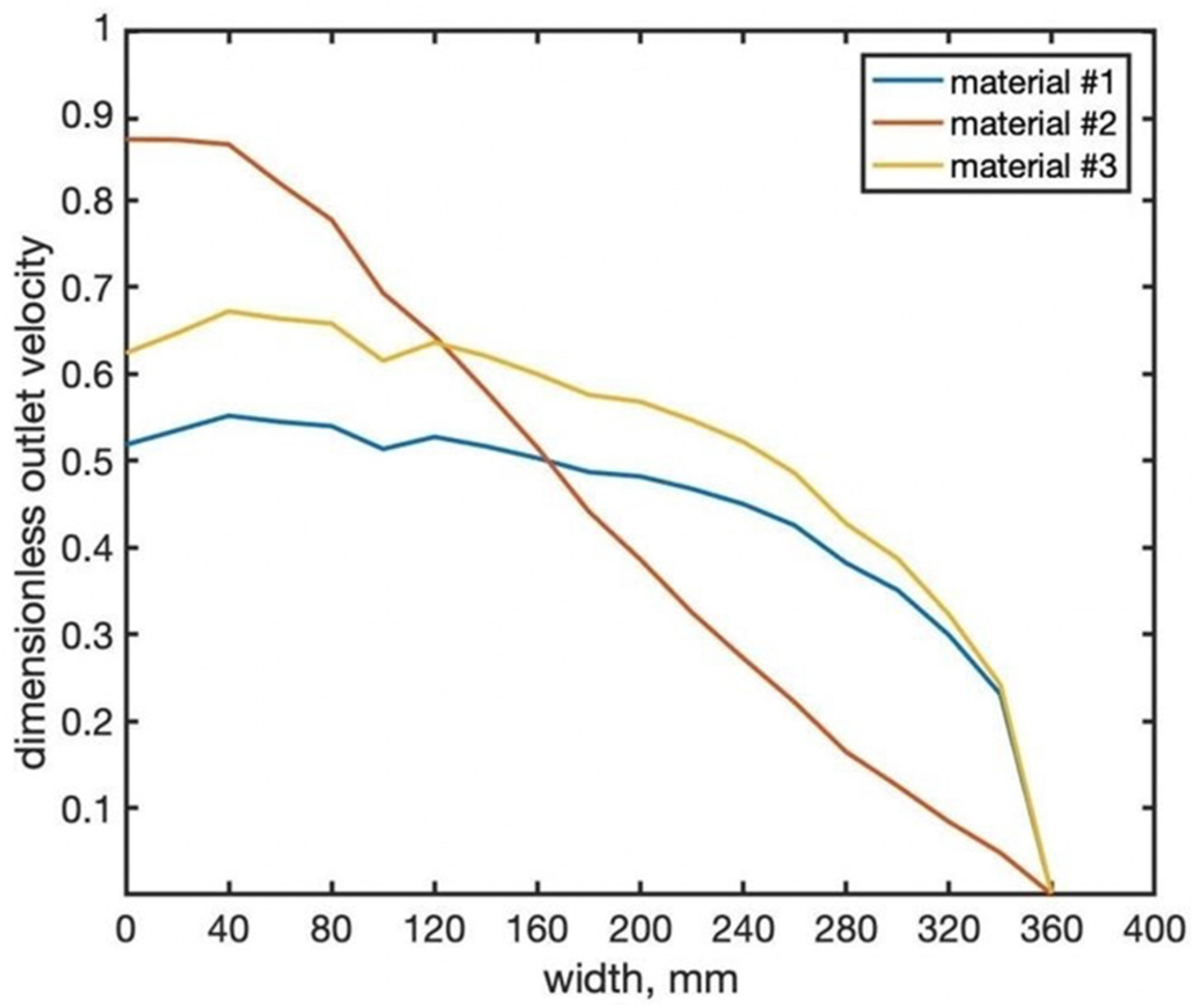
| Die exit average velocity variation |
| Simulation # | #1 | #2 | #3 | #4 | #5 |
|---|---|---|---|---|---|
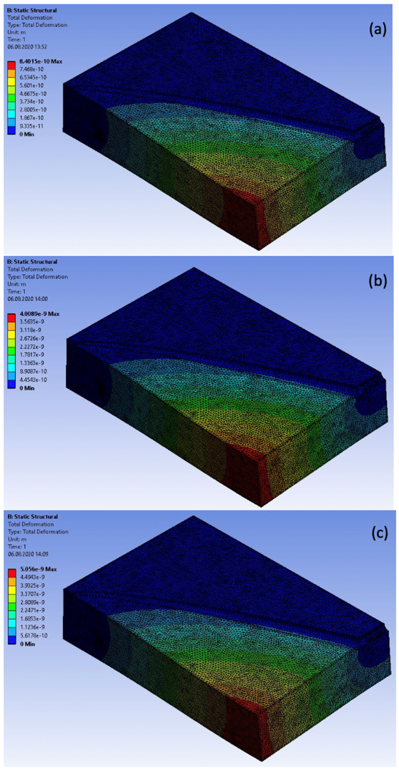
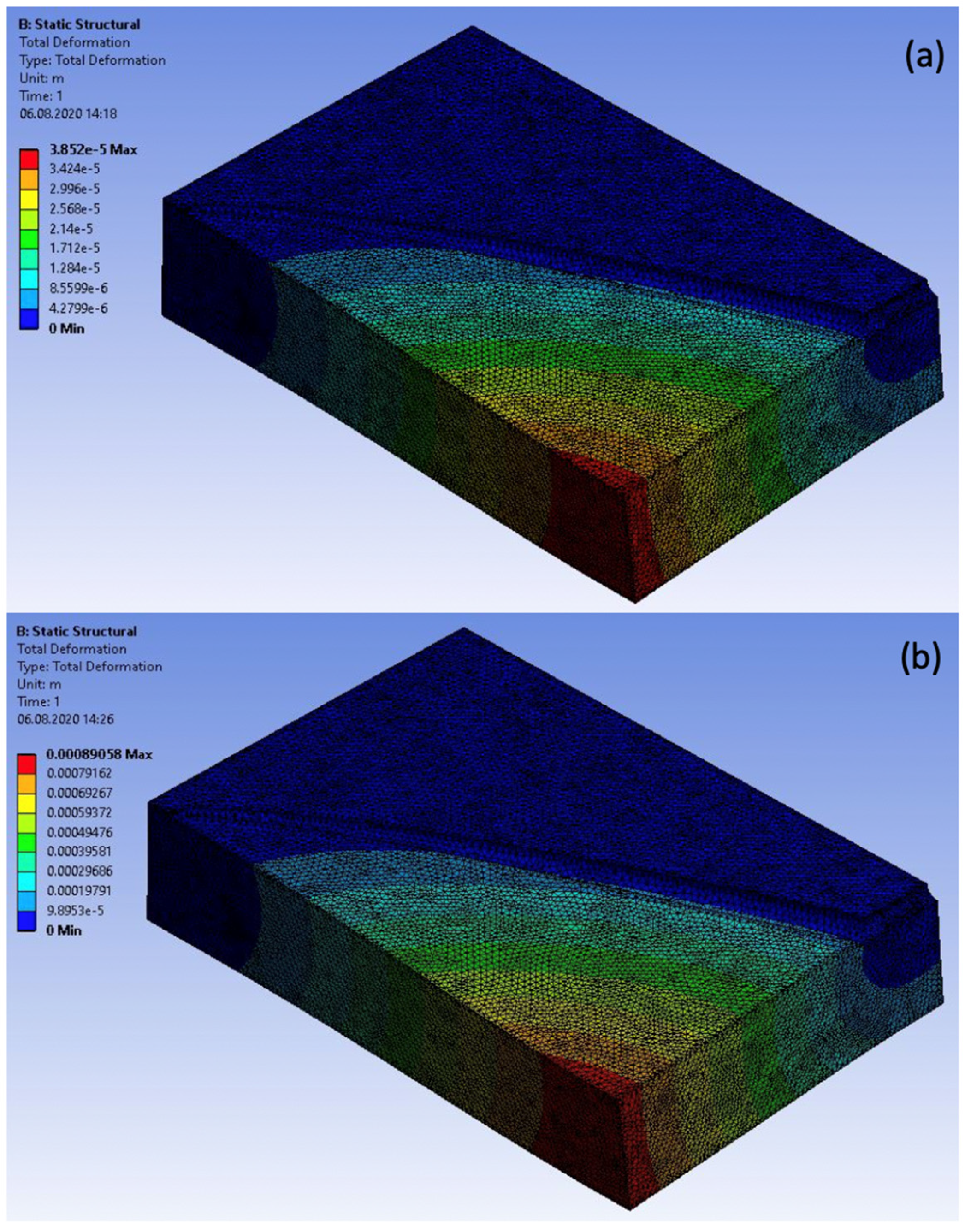
| Maximum von Mises stress, Pa |
Publisher’s Note: MDPI stays neutral with regard to jurisdictional claims in published maps and institutional affiliations. |
© 2020 by the authors. Licensee MDPI, Basel, Switzerland. This article is an open access article distributed under the terms and conditions of the Creative Commons Attribution (CC BY) license (http://creativecommons.org/licenses/by/4.0/).
Share and Cite
Igali, D.; Perveen, A.; Zhang, D.; Wei, D. Shear Rate Coat-Hanger Die Using Casson Viscosity Model. Processes 2020, 8, 1524. https://doi.org/10.3390/pr8121524
Igali D, Perveen A, Zhang D, Wei D. Shear Rate Coat-Hanger Die Using Casson Viscosity Model. Processes. 2020; 8(12):1524. https://doi.org/10.3390/pr8121524
Chicago/Turabian StyleIgali, Dastan, Asma Perveen, Dichuan Zhang, and Dongming Wei. 2020. "Shear Rate Coat-Hanger Die Using Casson Viscosity Model" Processes 8, no. 12: 1524. https://doi.org/10.3390/pr8121524