Article

Extensional Magnetorheology as a Tool for Optimizing the Formulation of Ferrofluids in Oil-Spill Clean-Up Processes

by
José Hermenegildo García-Ortiz
1 and
Francisco José Galindo-Rosales
2,*
1
Departamento de Ingeniería Mecánica y Diseño Industrial, Escuela Superior de Ingeniería, Universidad de Cádiz, Av. Universidad de Cádiz, 10, Puerto Real, 11519 Cádiz, Spain
2
Centro de Estudos de Fenómenos de Transporte (CEFT), Departmento de Engenharia Química, Faculdade de Engenharia da Universidade do Porto, Rua Dr. Roberto Frias s/n, CP4200-465 Porto, Portugal
*
Author to whom correspondence should be addressed.
Processes 2020, 8(5), 597; https://doi.org/10.3390/pr8050597
Submission received: 18 April 2020 / Revised: 9 May 2020 / Accepted: 11 May 2020 / Published: 17 May 2020
(This article belongs to the Special Issue Rheological Study of Nanofluids)

Abstract

:
In this study, we propose a new way of optimising the formulation of ferrofluids for oil-spill clean-up processes, based on the rheological behaviour under extensional flow and magnetic fields. Different commercial ferrofluids (FFs), consisting of a set of six ferrofluids with different magnetic saturation and particle concentration, were characterised in a Capillary Break-Up Extensional Rheometer (CaBER) equipped with two magnetorheological cells that allow imposing a homogeneous and tunable magnetic field either parallel or perpendicular to the flow direction. The filament thinning process with different intensities and orientation of the magnetic field with respect to the flow direction was analysed, and the results showed that the perpendicular configuration did not have a significant effect on the behaviour of the ferrofluids, as in shear magnetorheometry. However, the parallel configuration allowed to determine that the formulation of ferrofluids for oil-spill cleaning processes should consist of a 4% vol concentration of magnetic nanoparticles with a magnetic saturation of M s > 20 mT.

1. Introduction

As long as our model of society keeps consuming products derived from crude oil, oil spills and discharges will be unavoidable. However, they must be remediated to prevent their immediate and longterm detrimental impact on ecosystems’ health and severe economic consequences for the affected zones. Nevertheless, processes available for spills clean-up and mitigation are yet of limited recovery efficiency or have unaffordable energetic demands. Many approaches have been used to clean up the oil, e.g., by mechanical recovery [1], applied heat as in situ burning [2] or thermal desorption [3], using superhydrophobic materials [4]. Other authors [5] investigated the effectiveness of absorbent materials in the clean-up processes. Recently, Zahn et al. [6] proposed a magnetic clean-up process consisting of mixing synthesized magnetic nanoparticles and dispersing them in oil-polluted water in a vessel to form a ferrofluid either in the oil-phase or in the water-phase. To minimize the amount of magnetic nanoparticles, the magnetic fluid will be formed with phase presenting less volume, which is typically the oil-phase. When the mixture is placed in an oil-recovery vessel containing an array of specifically arranged permanent magnets, the magnetic fluid in the reservoir is attracted towards the lateral surface of the magnetic rods undergoing an extensional flow, as shown in Figure 1; and then the ferrofluid climbs to the top of the array, above reservoir level, forming beaded spheres around the magnets’ ends. The magnetic field thus separated the oil from the water phase much faster than gravity (phase-separation method by sedimentation), and without the use of electrical power. Though the design seems to work well, the efficiency of the magnetic separation process is yet to be determined. The performance of the magnetic separator will depend profoundly on the rheological properties of ferrofluids, as the flow imposed by the magnetic field is complex.
According to Solomon [7], ferrofluids (FFs) are colloidal suspensions of magnetic nanoparticles in a non-magnetic carrier fluid. Thus, technically, ferrofluids can be considered to be a magnetically controllable nanofluid [8,9]. Moreover, ferrofluids usually do not retain magnetization in the absence of an externally applied field and thus are often classified as “superparamagnets” [10]. The shear viscosity is independent on the shear rate and the intensity of the magnetic field [11], and consequently they behaves like a fluid in the presence of a magnetic field since the particles do not agglomerate under the influence of strong magnetic fields [12,13,14,15]. The rheological characterization of this type of fluids is traditionally carried out under shear flow by means of different devices, for example, capillary viscometers [16], capillary rheometer [17] or more commonly with rotational rheometers [11,14,18,19,20], under the influence of an external magnetic field oriented perpendicular to the direction of flow. However, to the best of authors’ knowledge, a systematic characterization of the FFs under extensional flow and an external magnetic field by controlling the intensity and orientation of the magnetic field has not yet been reported. In 2015, Galindo et al. [21] developed two magnetorheolgical cells consisting of permanent magnets that allowed to studying the effect of the magnetic field and its orientation on the filament thinning process of ferrofluids under extensional flow, but for a single value of the intensity of the magnetic field strength. More recently, Sadek et al. [22] developed a new version of these magnetorheological cells consisting of solenoids that allowed to control the intensity of the magnetic field by controlling the intensity current; however they only focused on the rheological characterization of magnetorheological fluids. If we intend to improve the oil-spill clean-up processes by means of the magnetic separator proposed by Zahn et al. [6], it is paramount to have a full rheological characterization of the ferrofluids, as it will allow for optimizing the formulation of the ferrofluids and modelling the fluid-flow in real configurations, where shear and extensional flow are coexisting, and the magnetic field may be oriented in any direction.
In this work, we report the rheological behaviour of 6 (3 water-based and 3 oil-based) commercial ferrofluids under the simultaneous application of a uniaxial extensional flow and an external magnetic field. The influence of the intensity and orientation of the magnetic field with regards to the flow direction will be analyzed. Moreover, the extensional properties of ferrofluids and their formulation will be correlated to maximize the efficiency of the magnetic cleaning-up process for the preservation of the ocean’s health.

2. Materials and Methods

2.1. Fluids

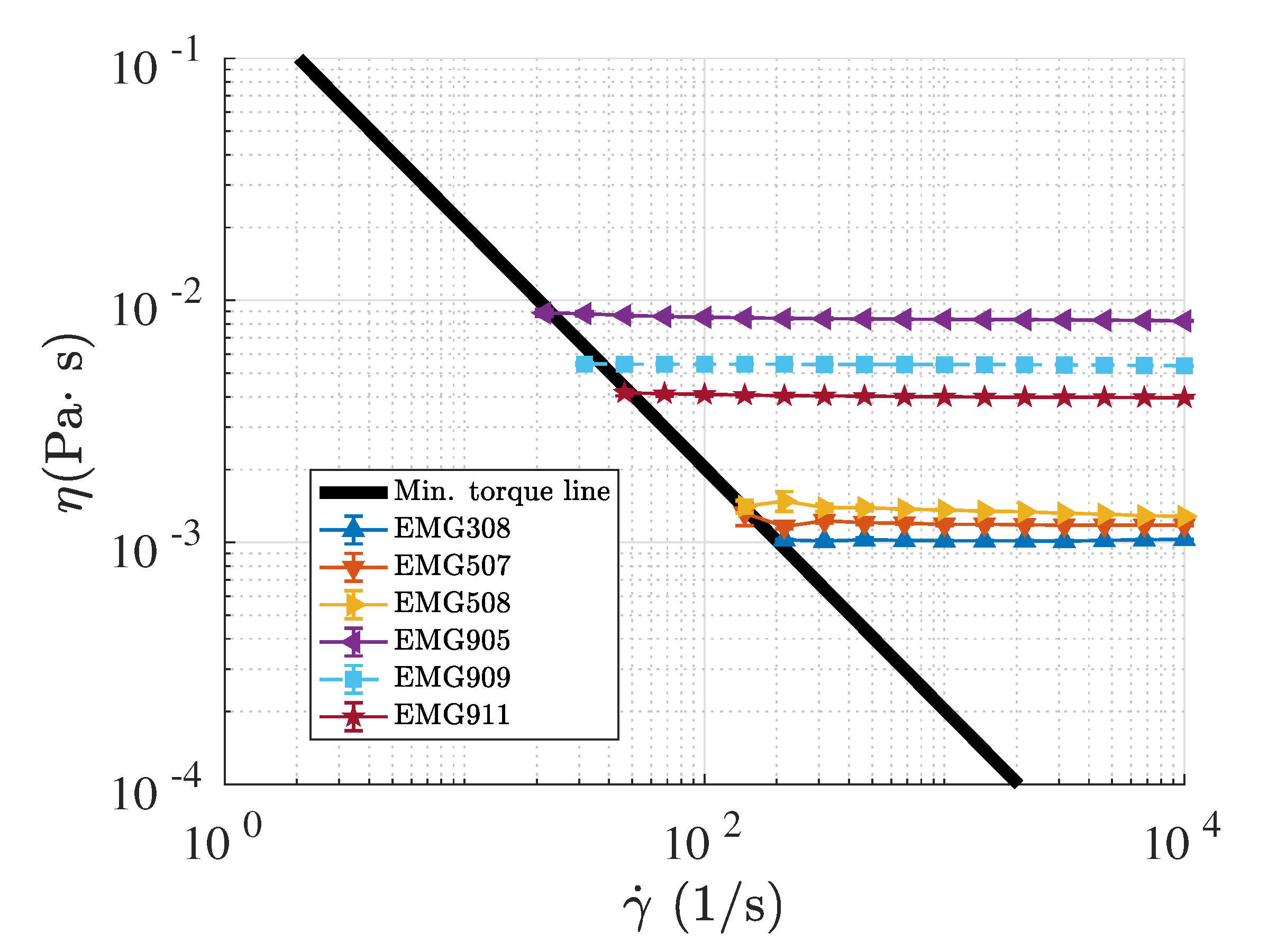
The ferrofluids considered in this study were selected from six different commercial FFs, three of them water-based and three oil-based. In all of them, the solid phase consisted of magnetic iron oxides nanoparticles-magnetite-(Fe 3 O 4 ) and the influence of their concentration, as well as their magnetic susceptibility, was considered. The properties are shown in Table 1, provided by the manufacturer, except for the surface tension and viscosity that were measured at 22 C and in the absence of an external magnetic field. For the surface tension, we used the Sigma 700 force tensiometer (Biolin Scientific, Espoo, Finland), equipped with a Du Noüy ring of 0.185 mm in thickness and 9.58 mm in diameter. The dynamic viscosity η was measured by means of a stress-controlled rotational rheometer (Anton Paar MCR301, Graz, Austria) using parallel plates of 50 mm and 0.1 mm gap (Figure 2). As the rheological properties of colloidal suspensions may depend on the dispersion quality [23], fresh samples were always used for each measurement after being redispersed in an ultrasound bath (Velleman VTUSC3, Gavere, Belgium) 6 min.

2.2. Capillary Breakup Extensional Magneto-Rheometry

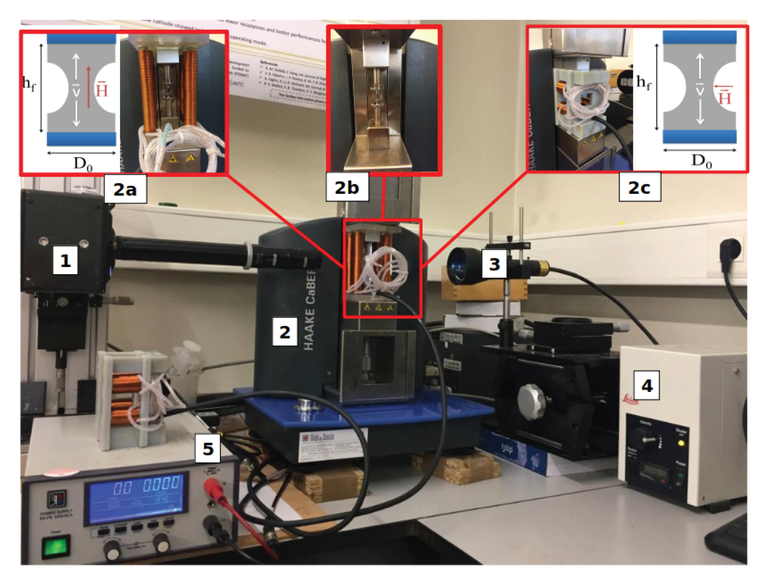
The experimental setup consists of a Capillary Breakup Extensional Rheometer (CaBER-1 device, Thermo Fisher Scientific, Waltham, MA, USA) equipped with the magnetorheological cell (ExMRFx) developed by Sadek et al. [22]. The CaBER device imposes a sudden extensional step strain (from h 0 to h f ) to a stable liquid bridge, reaching a state of unbalance in which capillary forces cause the filament thinning process until it breaks. By studying the temporal evolution of the minimum diameter of the filament, it is possible to characterize the extensional behaviour of the fluid [24,25]. The magnetorheological cells allow for the application of an external magnetic field of tunable intensity (H (kA/m)) in two different configurations: parallel and perpendicular to the direction of stretching (z-axis). Depending on the desired field direction, the corresponding configuration is easily installed in the CaBER. As shown in Figure 3, (2a) corresponds to the ExMRFx with parallel configuration, and (2c) with perpendicular configuration. The coils are connected in series to a DC power supply (PS 5200-02A, power supply, Elektro-Automatik, Viersen, Germany), which allows a current of up to 2A to be applied. Samir et al. [22] reported the correspondence between the current strength provided by the source and the field strength (H). Finally, for the case study of FFs without a magnetic field, the original configuration of CaBER is used (see Figure 3 (2b)). Due to the physical limitations of both the power supply and the coils, the maximum value of H that can be obtained with this device is 4 (kA/m). In this study, the intensity of fields applied, H, was set at 0, 1, 2, 3 and 4 kA/m. In the case of the water-based ferrofluids, due to their less sensibility to the presence of the magnetic field, we also used a permanent magnet device [21] to achieve higher intensity values: 12 kA/m (parallel) and 19 kA/m (perpendicular). At least three experiments were carried out for each case to ensure reproducibility of the results presented, and the temperature control was set to 22 C (Thermo Haake DC10, Karlsruhe, Germany). Besides initial and final gap was measured regularly using a set of thickness gauges, and a thermocouple sensor was used to monitor the fluid temperature.
As in Galindo-Rosales et al. [21], the filament thinning process was not recorded employing the laser system provided by the CaBER device, because the filament may not be symmetric with regards to a horizontal mid-plane. As an alternative, the entire thinning process was monitored employing a high-speed video camera (Photron FASTCAM Mini UX100, West Wycombe, Buckinghamshire, UK) assembled with a set of optical lenses (Optem Zoom 70 XL, Qioptiq, Fairport, New York, USA). To establish the correct illumination and achieve high contrast in the images of the liquid bridge profile, we used a 52 mm Telecentric Backlight Illuminator connected to a metal halide light source (LeicaEL6000, Leica Microsystems, Wetzlar, Germany) by an optical fibre cable. All the components of the experimental setup are indicated in Figure 3.

Slow Retraction Method (SRM)

Due to the low shear viscosity of the ferrofluid samples used in this study, which was smaller than 10 mPa · s (Table 1), according to Rodd et al. [26], the characterization of the extensional properties in the CaBER device is affected by inertial effects due to the fast step strain of the conventional technique, which introduces oscillations in the liquid that result in a loss of symmetry in the filament. (Figure 4a–d). Campo-Deanõ and Clasen [27] developed the so-called slow retraction method (SRM), which consists of recording the filament thinning process with a high-speed camera while the filament thinning process is promoted by a continuous and slow extension of the liquid bridge; in this way, the breaking process is orders of magnitude faster than the separation speed of the plates. By using the SRM, the effect of inertia due to quick plate separation in low-viscosity samples is minimized, as it can be seen in Figure 4e–f, where the oscillations in the last droplets were strongly reduced and the filament maintains its full symmetry up to the point of final breakage compared. Furthermore, it can be observed that SRM is independent of the CaBER stretching profile, as long as the separation rate of the plates remains much slower than the filament thinning process.
To summarize, all the results and discussions presented in the following section were obtained by using the 4 mm plates that separate from h 0 = 2 mm to h f = 6 . 25 mm with a separation speed of the plates 0.11 mm/s (strike time of t s = 38 . 63 s).

3. Results and Discusion

The appropriate dimensionless number characterising breakup process in the CaBER is the Ohnesorge number [28], which is defined as
O h = η 0 ρ σ R m i n ,
where η 0 , ρ , σ are the sample zero-shear viscosity, density and surface tension, respectively, whereas R m i n is the minimum radius of the filament. Then O h 1 = 0 is Stokes flow and O h = 0 gives inviscid flow. Presently, it is more common to use it as a relationship between the Reynolds number ( R e = ρ V c a p R η 0 ) and the Capillary number ( C a = η 0 V c a p σ ) defined in terms of the capillary velocity V c a p = σ η 0 as follows [29]:
O h 2 = R e C a = ρ σ R m i n η 0 2 .
To carry out the analysis and post-processing of the results, we need to know the value of the critical radius, R * , which corresponds approximately to the onset of the liquid bridge instability and when the filament thinning process gets started. According to Campo-Deaño et al. [27], this radius is reached for critical Ohnesorge number O h * = 0.2077 being
R * = 23 . 2 η 0 2 ρ σ
This critical radius is the reference from which we analyze the effect produced by the magnetic field on the filament thinning process of the different FFs.

3.1. Oil Based Samples

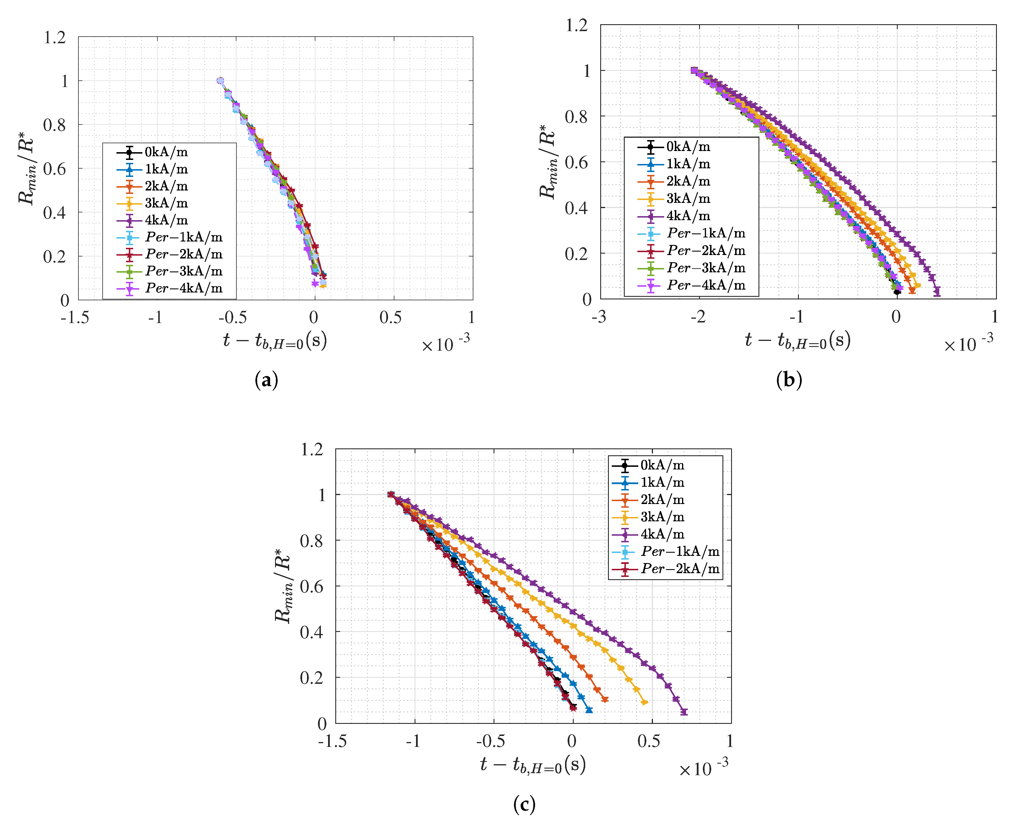
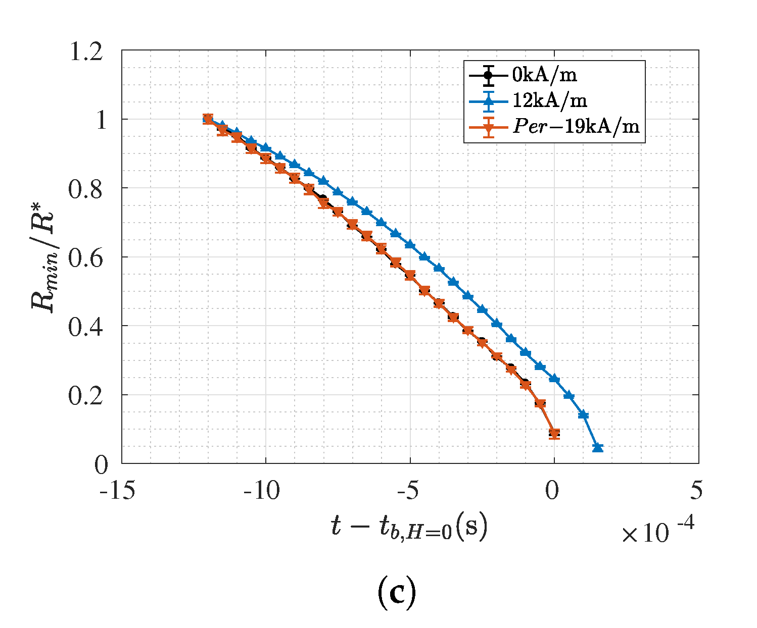
Figure 5a–c, shows the temporal evolution of the last stages of the minimum filament radius, normalised with R * , corresponding to the oil-based ferrofluids for the different intensities and orientation of the external magnetic field. The abscissas of the plots represent the time of the filament thinning minus the break-up time corresponding to the ferrofluid sample without the application of an external magnetic field ( t b , H = 0 )
When the magnetic field is perpendicular to the extensional flow direction, the temporal evolution of the normalized minimum radius follows the curve obtained in the case without the application of any magnetic field, as it is shown in Figure 5a–c. Thus, the presence of an external magnetic field perpendicular to the direction of the extensional flow does not have a significant effect in the thinning process of the ferrofluids. However, when the external magnetic field is oriented with the direction of the flow, the larger the intensity of the magnetic field, the longer the breakup time of the thinning process is. This influence of the magnetic field orientation on the filament thinning process is consistent with the results reported by Galindo-Rosales et al. [21]. As the magnetic field is aligned with the flow direction, the magnetic particles form structures that are aligned [14,30] with the fluid flow and the forces of the magnetic body that act as a result of their magnetization compensate for the effect of the surface tension more effectively than in the perpendicular configuration. Therefore, there is a significant field orientation dependence on the extensional behaviour of FFs, in contrast to their behaviour under shear [21]. Additionally, as expected, the effect of the parallel magnetic field becomes more significant when the values of ϕ , χ and M s increase in the ferrofluids.
Since the effect driven by the surface tension is only counteracted by the viscous resistance, the break-up time in the presence of a magnetic field parallel to the direction of the flow will be higher due to the magnetoviscous effect. The magnetoviscuos effect (MVE) measures the influence of the magnetic field strength on the shear viscosity of the magnetic suspension compared to the viscosity in the absence of a field [11,30,31,32]. Analogously, we define here an extensional magnetoviscous effect eMVE based on the extensional viscosity:
e M V E = η E ( H 0 ) η E ( H = 0 ) η E ( H = 0 )
where η E is the extensional viscosity defined as [33]:
η E ( ϵ ) = σ 2 d R m i n d t
being σ the surface tension.
Figure 6a shows the dependence of the extensional viscosity with the intensity of the external magnetic field applied parallel to the direction of the flow. As expected, the Trouton ratio for Newtonian fluids ( T r = η η E = 3 ) is respected at 0 kA/m. The larger the concentration of the particles and magnetization of the particles in the direction parallel to the extensional flow leads to a higher field-induced viscosity (see Figure 6a) and, consequently, the filament last longer, as discussed above (Figure 5a–c).

3.2. Water Based Samples

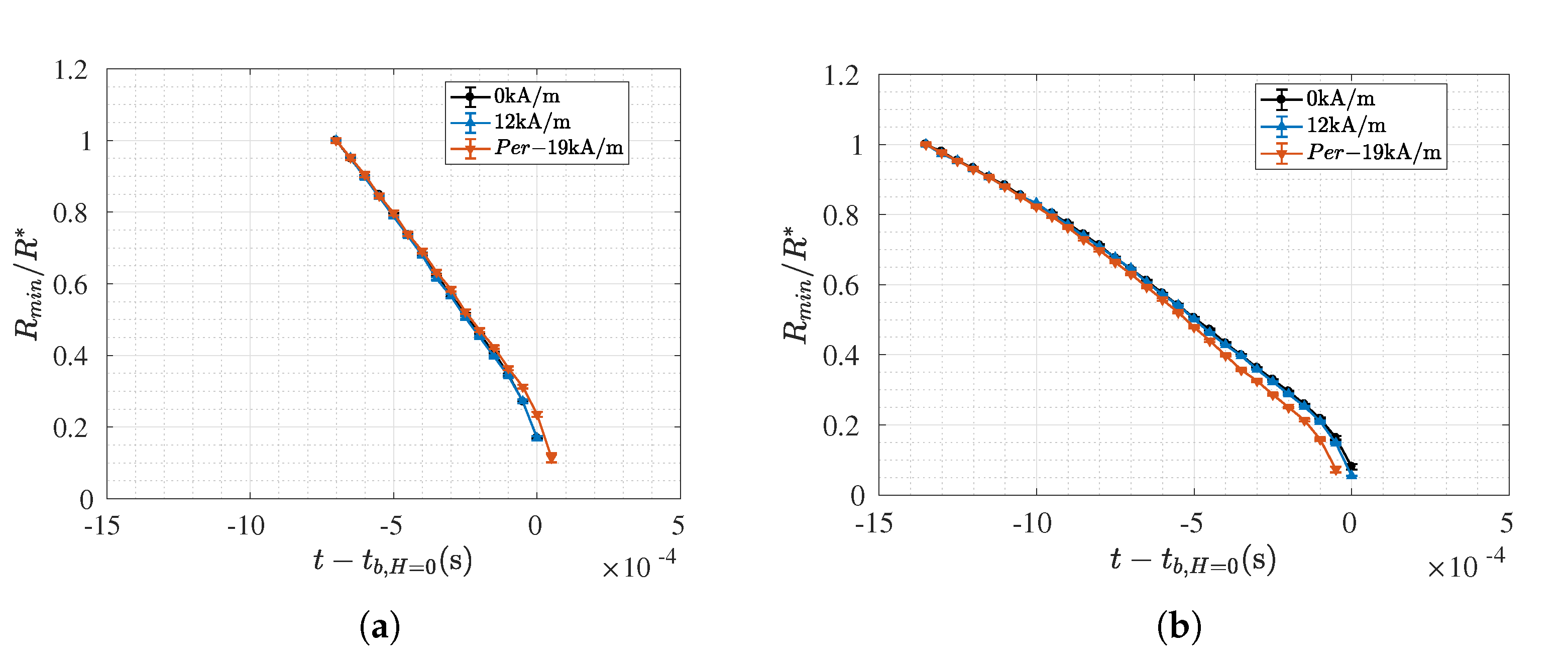
As in the previous section, the critical radius (Equation (3)) was determined for each sample based on the criterion Oh * = 0.2077. The results are shown in Figure 7, where it can be observed that the effect of the magnetic field on the aqueous-based ferrofluids is hardly perceptible. This result is in line with the ones shown in Figure 5, as the formulation of the water-based ferrofluids consists of particles with a magnetic saturation M s 11 mT and with a concentration ϕ 2 % vol (Table 1), which are values similar to the ones of EMG-911, the oil-based ferrofluid which did not exhibit any response to the external magnetic fields. Only the sample EMG-507 under the influence of H = 12 kA/m aligned with the flow direction exhibits a slight increase in the duration of the filament lifetime due to its small extensional magnetoviscous effect (∼0.106). As expected, this result is consistent with the eMVE calculated for the ferrofluid EMG-911 (Figure 6b), once both possess the same volume fraction and the same low magnetic saturation value. It cannot be conclude from this study the effect of the carrier fluid in the filament thinning process for the higher concentrated ferrofluids.

4. Conclusions

In this work, we characterized six FFs under the action of extensional flow using the CaBER device together with the magnetorheological cells that allow the application of a homogeneous and tunable magnetic field either parallel or perpendicular to the flow direction. The experiments were performed by using the slow restraction method, due to the low viscosity of the ferrofluids, under various magnetic field strengths and the two configurations. The magnetic field applied in the parallel direction caused an increase in the breakup time of the filament compared to the case without the presence of an external magnetic field. This is a consequence of an increase in extensional viscosity. However, when the magnetic field is applied perpendicularly to the flow direction, there was no significant modification of the filament thinning process, which means that the extensional viscosity remained unmodified under this configuration. This latter result is consistent with the results reported in the literature under simple shear flow, where the shear viscosity does not depend on the intensity of the magnetic field, which is also applied perpendicularly to the flow direction.
Thus, for the parallel configuration, it was possible to analyze the differences in the filament thinning process of the different ferrofluids, based on their formulation. It was possible to see that independently on the carrier fluid, the ferrofluids consisting on magnetic nanoparticles with a magnetic saturation M s 11 mT and a rvolume fraction ϕ 2 % vol are not sensible to magnetic fields with intensities H < 12 kA/m. Thus, these formulations should be avoided for the oil-spill cleaning process. Thus, considering the fact that magnetic nanoparticles are produced in small quantities, we would recommend to formulate ferrofluids with a concentration of ϕ ∼4% vol. and magnetic nanoparticles with at least a magnetic saturation of M s = 20 mT. Moreover, in order to maximize the oil separation in the magnetic separator proposed by Zahn et al. [6], the configuration of the magnets should promote the extensional flow with the magnetic field aligned to the flow direction.
Additionally, this magnetorheological characterization of ferrofluids under extensional flow can be also useful for optimizing the formulation of fluids for other industrial processes in which the extensional flow may be relevant, such as in printing processes with very low viscosity inks, where the addition of magnetic nanoparticles and the application of an external magnetic field aligned with the flow may be of help for improving the printing quality.

Author Contributions

Conceptualization, J.H.G.-O. and F.J.G.-R.; methodology, J.H.G.-O. and F.J.G.-R.; software, J.H.G.-O.; validation, J.H.G.-O. and F.J.G.-R.; formal analysis, J.H.G.-O. and F.J.G.-R.; writing–original draft preparation, J.H.G.-O.; writing—review and editing, F.J.G.-R.; supervision, F.J.G.-R.; project administration, F.J.G.-R.; funding acquisition, F.J.G.-R. All authors have read and agreed to the published version of the manuscript.

Funding

This research was funded by Fundação para a Ciência e a Tecnologia (FCT) through projects POCI-01-531 0145-FEDER-030765 (RheoOptimized2DInks), funded by FEDER funds through COMPETE2020—Programa Operacional Competitividade e Internacionalização (POCI) and with financial support of FCT/MCTES through national funds (PIDDAC), and MIT-EXPL/IRA/0077/2017 (FERRO-CLEAN). J.H.G.-O. also acknowledges “Programa de Fomento e impulso de la actividad investigadora de la Universidad de Cádiz 2018/19”.

Conflicts of Interest

The authors declare no conflict of interest. The funders had no role in the design of the study; in the collection, analyses, or interpretation of data; in the writing of the manuscript, or in the decision to publish the results.

Abbreviations

The following abbreviations are used in this manuscript:
CaBERCapillary Breakup Extensional Rheometer
ExMRFxExtensional Magneto-Rheological Fixture
FFsFerrofluids
SRMSlow Retraction Method
MVEMagnetoviscous effect
eMVEextensional Magnetoviscous effect

References

  1. Konishi, M.; Kishimoto, M.; Tamesui, N.; Omasa, T.; Shioya, S.; Ohtake, H. The separation of oil from an oil–water–bacteria mixture using a hydrophobic tubular membrane. Biochem. Eng. J. 2005, 24, 49–54. [Google Scholar] [CrossRef]
  2. Carrier, G.; Fendell, F.; Mitchell, J. In Situ burning via towed boom of oil spilled at sea. Combust. Flame 1992, 90, 295–306. [Google Scholar] [CrossRef]
  3. Araruna, J.; Portes, V.; Soares, A.; Silva, M.; Sthel, M.; Schramm, D.; Tibana, S.; Vargas, H. Oil spills debris clean up by thermal desorption. J. Hazard. Mater. 2004, 110, 161–171. [Google Scholar] [CrossRef] [PubMed]
  4. Darmanin, T.; Nicolas, M.; Guittard, F. Electrodeposited polymer films with both superhydrophobicity and superoleophilicity. Phys. Chem. Chem. Phys. 2008, 10, 4322–4326. [Google Scholar] [CrossRef]
  5. Teas, C.; Kalligeros, S.; Zanikos, F.; Stournas, S.; Lois, E.; Anastopoulos, G. Investigation of the effectiveness of absorbent materials in oil spills clean up. Desalination 2001, 140, 259–264. [Google Scholar] [CrossRef]
  6. Zahn, M.; Alan Hatton, T.; Shahriar Rhointon, K. Magnetic collid petroleum oil Spill clean-up of ocean surface, depth, and shore regions. Patent WO 2012/115814 A1, 14 February 2012. [Google Scholar]
  7. Papell, S.S. Low viscosity magnetic fluid obtained by the colloidal suspension of magnetic particles. U.S. Patent 3,215,572, 2 November 1965. [Google Scholar]
  8. Charles, S.W. The Preparation of Magnetic Fluids. In Ferrofluids: Magnetically Controllable Fluids and Their Applications; Odenbach, S., Ed.; Springer: Berlin/Heidelberg, Germany, 2002; pp. 3–18. [Google Scholar] [CrossRef]
  9. Taylor, R.; Coulombe, S.; Otanicar, T.; Phelan, P.; Gunawan, A.; Lv, W.; Rosengarten, G.; Prasher, R.; Tyagi, H. Small particles, big impacts: A review of the diverse applications of nanofluids. J. Appl. Phys. 2013, 113, 011301. [Google Scholar] [CrossRef]
  10. Voit, W.; Kim, D.K.; Zapka, W.; Muhammed, M.; Rao, K.V. Magnetic behavior of coated superparamagnetic iron oxide nanoparticles in ferrofluids. MRS Proc. 2001, 676, Y7.8. [Google Scholar] [CrossRef]
  11. Shahrivar, K.; Morillas, J.R.; Luengo, Y.; Gavilan, H.; Morales, P.; Bierwisch, C.; de Vicente, J. Rheological behavior of magnetic colloids in the borderline between ferrofluids and magnetorheological fluids. J. Rheol. 2019, 63, 547–558. [Google Scholar] [CrossRef]
  12. Behrens, S.; Bönnemann, H.; Matoussevitch, N.; Modrow, H.; Kempter, V.; Riehemann, W.; Wiedenmann, A.; Odenbach, S.; Will, S.; Eberbeck, D.; et al. Colloidal Magnetic Fluids: Basics, Development and Application of Ferrofluids; Springer: Berlin/Heidelberg, Germany, 2009; p. 430. [Google Scholar] [CrossRef] [Green Version]
  13. Iglesias, G.; López-López, M.; Delgado, A.; Durán, J. Description and performance of a fully automatic device for the study of the sedimentation of magnetic suspensions. Rev. Sci. Instruments 2011, 82. [Google Scholar] [CrossRef]
  14. López-López, M.T.; Gómez-Ramírez, A.; Rodríguez-Arco, L.; Durán, J.D.G.; Iskakova, L.; Zubarev, A. Colloids on the Frontier of Ferrofluids. Rheological Properties. Langmuir 2012, 28, 6232–6245. [Google Scholar] [CrossRef]
  15. Nogueras-Lara, F.; Rodríguez-Arco, L.; López-López, M.T. Dynamics of magnetic assembly of binary colloidal structures. EPL 2015, 111, 37002. [Google Scholar] [CrossRef] [Green Version]
  16. Mohammadfam, Y.; Heris, S.Z.; Khazini, L. Experimental Investigation of Fe3O4/hydraulic oil magnetic nanofluids rheological properties and performance in the presence of magnetic field. Tribol. Int. 2020, 142, 105995. [Google Scholar] [CrossRef]
  17. Hong, R.; Ren, Z.; Han, Y.; Li, H.; Zheng, Y.; Ding, J. Rheological properties of water-based Fe3O4 ferrofluids. Chem. Eng. Sci. 2007, 62, 5912–5924. [Google Scholar] [CrossRef]
  18. Susan-Resiga, D.; Vékás, L. Ferrofluid based composite fluids: Magnetorheological properties correlated by Mason and Casson numbers. J. Rheol. 2017, 61, 401–408. [Google Scholar] [CrossRef]
  19. Zhenkun, l.; Yao, J.; Li, D. Research on the Rheological Properties of a Perfluoropolyether Based Ferrofluid. J. Magn. Magn. Mater. 2016, 424. [Google Scholar] [CrossRef]
  20. Zhenkun, l.; Li, D.; Cui, H.; Zhang, Y.; Wang, H. Influence of the Carrier Fluid Viscosity on the Rotational and Oscillatory Rheological Properties of Ferrofluids. J. Nanosci. Nanotechnol. 2019, 19, 5572–5581. [Google Scholar] [CrossRef]
  21. Galindo-Rosales, F.J.; Segovia-Gutiérrez, J.P.; Pinho, F.T.; Alves, M.A.; de Vicente, J. Extensional rheometry of magnetic dispersions. J. Rheol. 2015, 59, 193–209. [Google Scholar] [CrossRef]
  22. Sadek, S.H.; Najafabadi, H.H.; Galindo-Rosales, F.J. Capillary breakup extensional magnetorheometry. J. Rheol. 2020, 64, 55–65. [Google Scholar] [CrossRef]
  23. Galindo-Rosales, F.J.; Moldenaers, P.; Vermant, J. Assessment of the dispersion quality in polymer nanocomposites. Macromol. Eng. 2011, 296, 331–340. [Google Scholar] [CrossRef] [Green Version]
  24. McKinley, G.H.; Tripathi, A. How to Extract the Newtonian Viscosity from Capillary Breakup Measurements In a Filament Rheometer. J. Rheol. 2000, 44, 653–671. [Google Scholar] [CrossRef] [Green Version]
  25. McKinley, G.H. Visco-Elasto-Capillary Thinning and Break-Up of Complex Fluids; Rheology Reviews; The British Society of Rheology: Aberystwyth, UK, 2005. [Google Scholar]
  26. Rodd, L.; Scott, T.; Cooper-White, J.; McKinley, G.H. Capillary break-up rheometry of low-viscosity elastic fluids. Appl. Rheol. 2005, 15, 17–27. [Google Scholar] [CrossRef] [Green Version]
  27. Campo-Deaño, L.; Clasen, C. The slow retraction method (SRM) for the determination of ultra-short relaxation times in capillary breakup extensional rheometry experiments. J. Non-NEwtonian Fluid Mech. 2010, 165, 1688–1699. [Google Scholar] [CrossRef] [Green Version]
  28. Li, Y.; Sprittles, J.E. Capillary breakup of a liquid bridge: Identifying regimes and transitions. J. Fluid Mech. 2016, 797, 29–59. [Google Scholar] [CrossRef] [Green Version]
  29. McKinley, G. Free surface flows of complex fluids. Rheol. Bull. 2005, 74, 6–10. [Google Scholar]
  30. Ilg, P.; Odenbach, S. Ferrofluid Structure and Rheology. In Colloidal Magnetic Fluids: Basics, Development and Application of Ferrofluids; Odenbach, S., Ed.; Springer: Berlin/Heidelberg, Germany, 2009; pp. 1–77. [Google Scholar] [CrossRef]
  31. Odenbach, S.; Thurm, S. Magnetoviscous Effects in Ferrofluids. In Ferrofluids: Magnetically Controllable Fluids and Their Applications; Odenbach, S., Ed.; Springer: Berlin/Heidelberg, Germany, 2002; pp. 185–201. [Google Scholar] [CrossRef]
  32. Santiago-Quinones, D.; Raj, K.; Rinaldi, C. A comparison of the magnetorheology of two ferrofluids with different magnetic field-dependent chaining behavior. Rheol. Acta 2013, 52. [Google Scholar] [CrossRef]
  33. Anna, S.; McKinley, G. Elasto-capillary thinning and breakup of model elastic liquids. J. Rheol. 2001, 45, 115. [Google Scholar] [CrossRef] [Green Version]
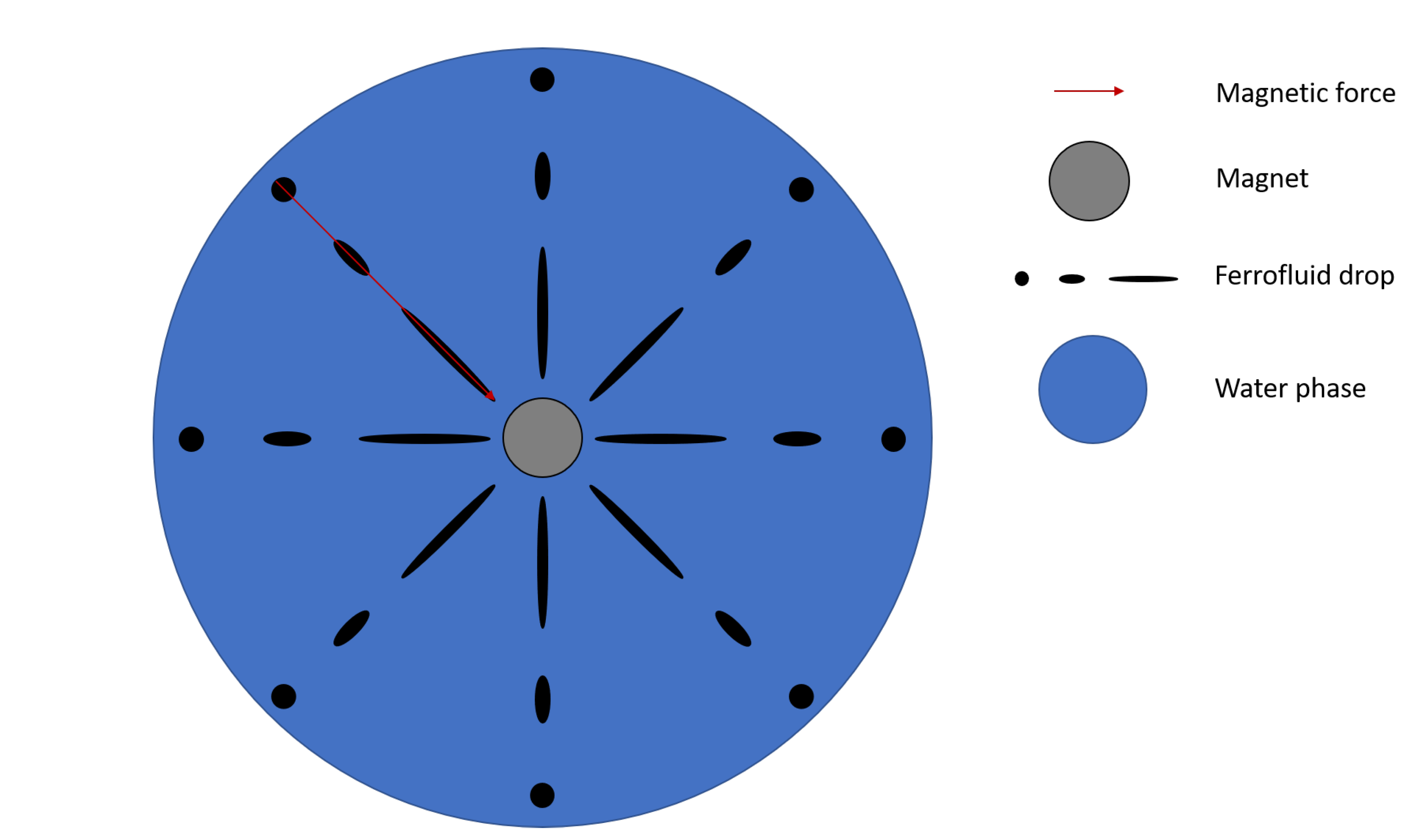
Figure 1. Sketch of the magnetic separator unit proposed by Zahn et al. [6], consisting of a single magnetic rod. In this top view, it is represented how the gradient of magnetic field generates a magnetic force attracting the ferrofluid droplets towards the magnet. As the surrounding water and air move freely, the ferrofluid drop is undergone to a shear-free extensional flow.
Processes 08 00597 g001
Figure 2. Viscosity curve of the ferrofluids in the absence of an external magnetic field.
Processes 08 00597 g002
Figure 3. Experimental setup: (1) High-speed camera; (2) CaBER device: (2a) ExMRFx with parallel configuration, (2b) non-magnetic field, and (2c) ExMRFx with perpendicular configuration; (3) Telecentric Backlight Illuminator; (4) light source; (5) DC power source.
Processes 08 00597 g003
Figure 4. Comparison of the final filament shape obtained when imposing a fast separation rate of the plates provided with the three different streching profiles available in the CaBER device (ad) for the EMG-905 sample, and when using the SRM method (e,f) with a plate separation rate set at 0.11 mm/s in SRM. No external magnetic field was imposed in this prelimiary tests.
Processes 08 00597 g004
Figure 5. Time evolution of the normalised minimum radius ( R m i n / R * ) under the application of an external magnetic field with different intensities and different orientations. Each plot corresponds to each oil-based ferrofluid, where Per referes to the perpendicular configuration.(a) EMG-911, (b) EMG-909, (c) EMG-905.
Processes 08 00597 g005
Figure 6. The figure shows the characteristic extensional viscosity (a) and eMVE (b) as a function of the field strength.
Processes 08 00597 g006
Figure 7. Time evolution of the normalised minimum radius ( R / R * ) under the application of an external magnetic field with different intensities and different orientations. Each plot corresponds to each water-based ferrofluid, where Per referes to the perpendicular configuration and only the curves corresponding to the highest intensity fields are shown for the sake of clarity. (a) EMG-308, (b) EMG-508, (c) EMG-507.
Processes 08 00597 g007aProcesses 08 00597 g007b
Table 1. Main properties of the ferrofluids considered in this study.
EMG-905EMG-909EMG-911EMG-308EMG-507EMG-508
ρ (kg/m 3 ) at 25 C12001020890106011201070
η (mPa · s) at 22 C9.81 ± 0.075.90 ± 0.024.04 ± 0.041.02 ± 0.011.20 ± 0.011.35 ± 0.02
σ (mN/m)22.7623.6623.7558.6458.6650.48
a (nm)∼10∼10∼10∼10∼10∼10
M s (mT)4422116.6116.6
χ 3.521.380.500.501.630.88
ϕ (% vol)7.83.921.221.2
Where ρ is the density, η is the shear viscosity, σ is the surface tension, a is the nominal particle diameter, M s is the magnetic saturation, χ is magnetic susceptibility, and  ϕ is the volume fraction of MNPs in the ferrofluid.