Abstract
There are cases where the output of renewable eappennergy (RE) is curtailed due to an increase in the share of RE. Typically, wind power (WP) is curtailed due to oversupply and low loads at midnight. However, there are cases where the output of WP is limited during the daytime due to the increase in the share of photovoltaics (PV). In the current electricity market, as the share of PV is increased, the curtailments of WP will be increased further, which will add to the difficulties experienced by wind farm operators. This paper proposes a supervisory power coordination scheme. The main purposes are to prevent the penetration of extra power from REs into the grid; thus, the curtailments can be prevented. In order to make it feasible, the proposed scheme is to design a grid-connected microgrid system to be operated only in response to loads and virtual power plant (VPP) requests. The effectiveness of the proposed scheme was verified by simulation studies conducted in the MATLAB/Simulink environment. The verification was conducted based on the voltage criteria, such as the AC voltage regulation between ±6% of the rated AC voltage, the DC voltage regulation between ±10% of the rated DC voltage, the power balance according to variations in the loads, and VPP requests for power. The simulation showed that the proposed scheme is feasible and justifiable, not only to mitigate the power curtailment problem but also to apply different system configurations.
1. Introduction
Due to the binary nature of electricity, microgrids are broadly classified as AC and DC microgrids. However, to comply with the AC system and to interface with the growing DC technologies, coupled AC and DC grids, or AC/DC hybrid microgrid structures, are currently receiving significant attention. The advantage of this structure is that it can accommodate both AC and DC loads and generators instantaneously with minimum AC/DC/AC power conversion. In addition, this structure is suitable for integrating distributed storage such as in the emerging electric vehicle energy storage systems (EV-ESS) for vehicle-to-grid (V2G) applications [1].
High-voltage direct current has been used to connect large-scale grid connections between countries and to incorporate large wind farms into transmission systems. In medium- or low-voltage systems, due to an increase in DC loads and inverter-interfaced distribution generation, DC grids are constructed by converting the AC operations to DC. This can cause electricity losses as well as incurring the initial capital costs associated with voltage-sourced converters (VSCs), but it can control the line power flow and increase the power capability [2]. In addition, the DC power grid can be more efficient in integrating renewable energy sources [3,4]. The development of DC grids has led to AC/DC hybrid microgrids. The advantage of an AC/DC hybrid microgrid is that it reduces the number of energy conversion stages and combines the benefits of AC and DC systems [5].
A microgrid refers to a small-scale distribution network designed to actively manage the power and energy locally, which is essentially an active distribution system [2]. The concept of the AC/DC hybrid microgrid is the same as a conventional pure AC microgrid, but with the addition of a DC grid. A static switch is placed at the point of common coupling or point of interconnection, and there are various energy resources and some controllable loads in AC/DC hybrid microgrids. Typically, but not necessarily, AC loads are in the AC grid and DC loads are in the DC grid. The purpose of such a configuration is to improve energy efficiency. The energy resources are also placed similarly.
Unlike the typical structure in which the main grid is connected to the AC grid, in the AC/DC hybrid microgrid structure, the DC grid is linked to the main grid through the power conversion devices, and static switch is possible [6]. In this structure, the frequency of the AC grid can differ from the main grid due to two voltage conversions (between the DC grid and the main grid, and the DC grid and the AC grid). This structure is more typical at the medium or high voltage level to interconnect with other regions.
One major issue with the current power system is the introduction of DC technology into the system. Initially, DC devices were connected to the AC grid via inverters, but as the number of DC devices increases and the awareness of energy efficiency rises, more DC grids in which the energy is transmitted through the DC line are now being constructed. In the DC grid, there is no system frequency or reactive power flow. Frequency acts as a global variable, and it can be used to recognize the generation and load mismatch in the AC power grid. However, in the DC power grid, the DC voltage is used in a similar way, but it may not provide accurate information because the voltage magnitude is different in the buses due to line resistance. In addition, the voltage should be regulated by the active power.
As typical control schemes, hierarchical microgrid controls have been researched substantially [7,8,9,10,11,12,13,14,15,16,17,18,19]. However, it is shown that such an autonomous control scheme fails to function due to variations such as droop coefficients and the loss/connection of renewable energy sources.
Power curtailment issues have recently arisen due to the high penetration of REs into grids. Approximately 6.5 million MWh of PV output was curtailed in Chile, China, Germany, and the United States [20]. It is difficult for grid operators to manage a great number of distributed energy resources (DERs) without visibility.
In the United States, a network operation center (NOC)-type load management business model that remotely controls demand response resources using a communication network is active, centering on private companies such as EnerNOC and Comverge.
Portland General Electric (PGE) is developing its own self-contained 45 MW generator composed of 32 generators in 21 consumer districts in Oregon through a Dispatchable Standby Generation (DSG) program that integrates consumer-owned emergency generators rather than demand response and uses them to reduce peak loads.
The driving force behind VPP development in the EU is the expansion of RE and distributed generation (DG) distributions and energy efficiency improvements for reducing greenhouse gas emissions and relieving dependence on fossil fuels. In other words, in order to actively respond to problems related to stability and power quality in the distribution network that may occur due to the expansion of RE and DG distributions, and to allow small DERs to participate in the power market, this dispersion is used to improve the overall system operation efficiency. A technology platform for the integrated operation and control of these types of resources is the core of the VPP concept in the EU.
In Jeju, Korea, the number of curtailments increased from 7 in the year 2018 to 77 in the year 2020, which is related to a waste of energy totaling 19,449 MWh. The expected number of power curtailments in the year 2021 is 240, meaning that 60,000 MWh of energy will be wasted. Thus, Korea has recently urged the mitigation of power curtailments utilizing ESSs, as well as technical innovation of the photovoltaic system.
This paper proposes a supervisory power coordination scheme to prevent excessive power generation from REs. The key technology is a scheme that corresponds only to load variations and VPP requests.
2. System Descriptions
- A.
- System Configuration
Figure 1 indicates the proposed system configuration. All AC and DC components are interlinked at the DC common bus. The AC subgrid is represented by the AC constant voltage source, the AC load, and the VPP’s request and is linked to the DC common bus through the AC/DC interlinking converter (IC) with the LCL filter. The DC subgrid consists of an ESS and a PV and is connected to the DC common bus through its own DC/DC converter. The AC load is modeled as single-phase resistance, and its voltage is assumed to be AC 220 V. The VPP’s request is assumed to be kW time step variations in the active power. The ESS is expressed by the battery and the bidirectional DC/DC converter with the associated controller, and its capacity is assumed to be 15 kWh. Finally, the PV is modeled by the PV arrays and the boost DC/DC converter with its associated MPPT control, and its capacity is considered to be 11 kW.
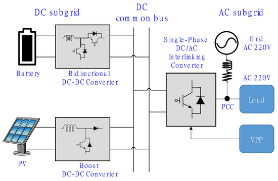
Figure 1.
The architecture of the proposed AC/DC-interlinked hybrid microgrid.
The overall system model is simulated at the sampling time of s. In order to realize a real-time simulation, the sampling time of the controller is set to s to take into account the communication delays. The switching frequency of all converters is assumed to be 20 kHz. Detailed information about the dynamic simulation parameters and sub-models can be found in Appendix A and Appendix B, respectively.
- B.
- Point of Common Coupling (PCC)
The PCC is located between the AC load and the AC/DC interlinking converter (IC), as shown in Figure 1.
- C.
- AC/DC Interlinking Converter (IC)
Switch 1 in the AC/DC interlinking converter plays an important role according to the state of charge (SOC) of the battery. According to the SOC and the VPP’s request, switch 1’s operations can be briefly summarized as follows:
- (1)
- If : the ESS charges until the SOC reaches its pre-defined value (e.g., 50% in this paper), and the DC link voltage is controlled by the IC.
- (2)
- If : the DC link voltage is controlled by the ESS, and the constant voltage-constant frequency (CVCF) is controlled by the IC.
- (3)
- If VPP’s request: the DC link voltage is controlled by the ESS, and the active power is controlled by the IC.
The pre-defined value of the SOC is changeable with respect to the system operating conditions.
As illustrated in Figure 2, the IC controller consists of a second-order generalized integrator (SOGI)-based phase-locked loop (PLL), a proportional–integral (PI)-based current and voltage controller, etc. The parameters are presented in Appendix A. Dynamic models for the rest of the blocks such as SVPWM, Park Transformation, and All Pass Filter can be found in [21].
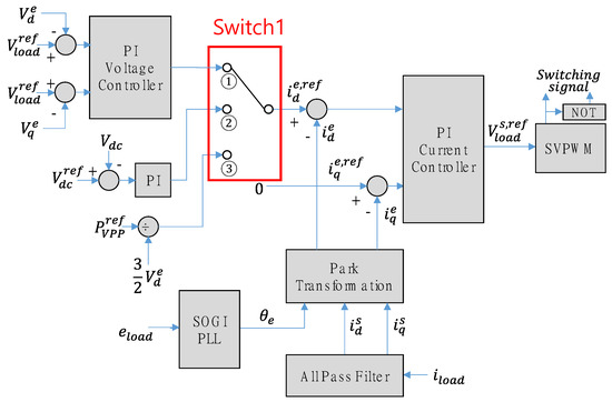
Figure 2.
Control block diagram of the AC/DC interlinking converter (IC).
- D.
- Energy Storage System (ESS)
The modeling is carried out based on concepts presented in [22]. Here, the ESS is modeled by the battery, the bidirectional DC/DC converter, and the associated controls in order to perform the discharging and charging operations [23]. The parameters of the PIs are presented in Appendix A.
Figure 3 presents the control block diagram of the bidirectional DC/DC converter. Switch 2′s operations can be summarized as follows:
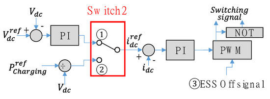
Figure 3.
Control block diagram of the bidirectional DC/DC converter of the ESS.
- (1)
- If : the DC link voltage is controlled by the ESS, PV MPPT ON, and the CVCF is controlled by the IC, Grid OFF.
- (2)
- If : PV MPPT ON, the DC link voltage is controlled by the IC, and the active power is controlled by the ESS until the SOC reaches its pre-defined value.
- (3)
- If : this defines the emergency situation; thus, the ESS is set to STOP.
- E.
- Photovoltaic System (PV)
The PV consists of models of the PV arrays, the DC/DC converter, and the associated control MPPT. The equivalent circuit used in the model is the one-diode model with shunt and series resistance. More detailed information can be found in [22].
Switch 3′s operations in Figure 4 can be simply described as follows:
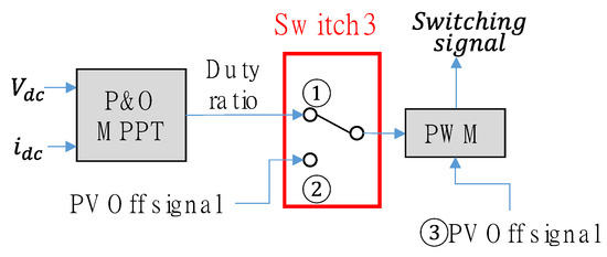
Figure 4.
Control block diagram of the boost DC/DC converter of the PV.
- (1)
- If : PV MPPT ON, the DC link voltage is controlled by the ESS; Grid OFF, the CVCF is controlled by the IC.
- (2)
- If : PV OFF, the ESS discharges until the SOC reaches the pre-defined value; Grid OFF, the CVCF is controlled by the IC.
- (3)
- If : PV OFF, the ESS charges until the SOC reaches the pre-defined value, and the DC link voltage is controlled by the IC, Grid ON.
- F.
- Virtual Power Plant (VPP)
The VPP’s request is represented by the kW time step variation. Such a representation takes into account the power trade between the DC subgrid with the load and the VPP, as shown in Figure 1. In this paper, a positive VPP request is considered to be when the power flow is from the AC grid to the DC subgrid and the load. A negative VPP request is considered to be when the power flows from the DC subgrid with the load to the AC grid. There may not be sufficient power reservoirs in the DC subgrid in order to fully respond to the VPP’s request . Thus, the final VPP request described in Figure 2 is limited by taking into account the battery SOC or the battery voltage , as defined in Equations (1) and (2), respectively. In this paper, Equation (1) was adapted due to its conventional use in industry applications.
3. Supervisory Power Coordination Scheme
This section presents the supervisory power coordination scheme. The overall objective is to distribute the power required by the loads and VPPs by taking into account the operating conditions of the REs. This, in turn, means that the power supply to the load only comes from the REs. The power exchange between the REs and the grid only occurs when there is a request from the VPP so that there is no extra power penetration into the grid. As a result, any power curtailment of REs connected to the grid can be prevented; subsequently, the sale and purchase of power can be performed only when required, without harming the stability of the system. Figure 5 shows a visual comparison between conventional operations and the proposed operations.
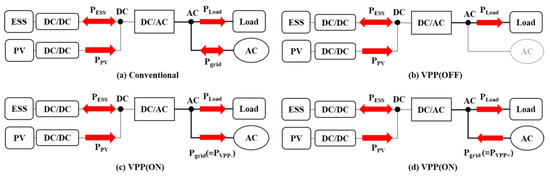
Figure 5.
Comparison between the conventional and proposed operations.
In Section 2, the switch operations of the proposed control schemes were briefly introduced. In this section, the proposed operation process is described based on Figure 6.
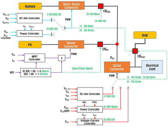
Figure 6.
The overall implementation block diagram for the proposed scheme.
Figure 7 and Figure 8 are representations of Figure 6. Figure 7 is the case when there is a VPP request. Figure 8 is the case when there is no VPP request. The pre-defined SOC parameters shown in Figure 7 and Figure 8 were used for the simulation studies. The VPP’s request means there is a power trade between the AC grid and the DC subgrid with the loads. Moreover, the pre-defined SOC value can be changed according to the system characteristics and overall system operating conditions.
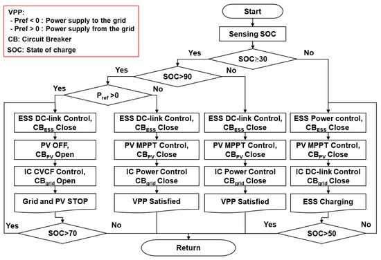
Figure 7.
The proposed supervisory power coordination scheme with a VPP request.
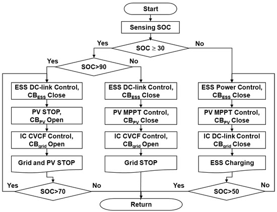
Figure 8.
The proposed supervisory power coordination scheme without a VPP request.
4. Case Studies
The simulation studies were conducted in the MATLAB/Simulink environment [24]. The simulation models are presented in Appendix B. The simulation conditions are summarized as follows (Table 1):

Table 1.
System Parameters.
Figure 9 shows the comparison between the VPP’s request () and VPP’s reference (). As illustrated in Figure 9, the VPP’s reference is generated without violating the system operating conditions of the SOC according to Equation (1). A positive VPP request is considered to be when the power flow is from the AC grid to the DC subgrid and the load. A negative VPP request is considered to be when the power flow is from the DC subgrid with the load to the AC grid.
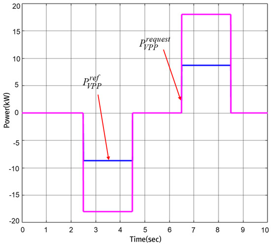
Figure 9.
Comparison between the VPP’s request and the VPP’s reference.
Figure 10 and Figure 11 show the voltage response and the power response, respectively. As shown in Figure 10, the voltage at each component output is well regulated within the required operating range, such as the AC voltage between and the DC voltage between . Figure 9 shows the performance of the power balance between the generation and consumption according to the variations in the loads and the VPP request power. In Figure 11, the DC subgrid performs well with the load variations. Moreover, the power trade, according to the VPP, is conducted sufficiently without violating the SOC condition-based criteria defined in Equation (1).
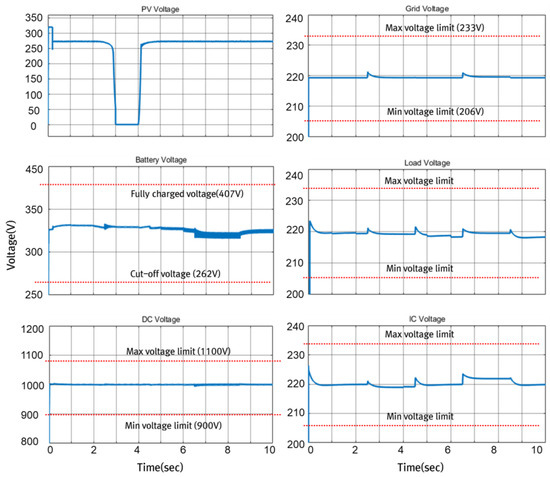
Figure 10.
Comparison among voltages.
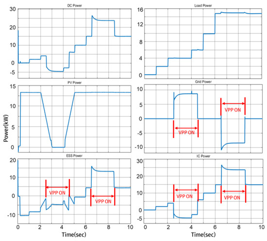
Figure 11.
Comparison among powers.
5. Discussion
As depicted in the simulation studies, the supervisory power coordination performs well. When there is no VPP request, the power supply to the AC load is handled not by the grid, but by the DC subgrid (PV + ESS). When there is a VPP request, the ESS turns to the charging or discharging operation mode, while the PV generates its maximum power. The VPP’s request is limited by the boundary conditions defined in Equation (1); thus, a proper VPP request is achieved without violating the system operating conditions. As a result, the proposed system architecture and the supervisory power coordination scheme are well justified.
6. Conclusions
This paper proposed a supervisory power coordination scheme. As demonstrated in the simulation, the supervisory power coordination scheme performed well in terms of the responses to the load and the VPP’s request from the perspective of the power balance between the AC subgrid and the DC subgrid. In the proposed scheme, the pre-defined SOC parameters can be changed according to the system operating conditions. Furthermore, as depicted in the simulation studies, it is important to consider the system operating conditions, especially when a VPP request is required. Conclusively, the proposed system configuration and supervisory power coordination scheme demonstrate innovative performance in the prevention of excessive power penetration of REs into the grid, as well as contributing to VPP requests. The proposed scheme is readily applicable, reasonable, and justifiable in terms of its application in a variety of system configurations.
Author Contributions
Conceptualization, H.K. and G.K.; methodology, H.K.; software, G.K.; validation, G.K. and Y.N.; formal analysis, H.K.; investigation, G.K.; resources, Y.N. and K.R.; data curation, Y.N.; writing—original draft preparation, H.K.; writing—review and editing, H.K.; visualization, Y.N. and K.R.; supervision, H.K. All authors have read and agreed to the published version of the manuscript.
Funding
This research received no external funding.
Institutional Review Board Statement
Not applicable.
Informed Consent Statement
Not applicable.
Data Availability Statement
Not applicable.
Acknowledgments
This research was funded by the Ministry of Trade, Industry and Energy, and supported by the Korea Institute for Advancement of Technology (KIAT) (grant number P083700028). This work was also supported by a grant from the Korea Agency for Infrastructure Technology Advancement (KAIA), funded by the Ministry of Land, Infrastructure and Transport (grant number 21HSCTB157908-02).
Conflicts of Interest
The authors declare no conflict of interest.
Appendix A
Table A1.
System Parameters.
Table A1.
System Parameters.
| ESSs | |
| Nominal power | 15 kWh |
| Nominal discharging current | 18 A |
| Cut-off voltage | 262 V |
| Maximum SOC | 90% |
| Fully charged battery voltage | 407 V |
| Nominal voltage | 350 V |
| Emergency maximum SOC | 95% |
| PWM generator | |
| (Boost and buck) | |
| PI controller integral gain | 2 |
| PI controller proportional gain | 50 |
| (DC control) | |
| PI controller proportional gain | 20 |
| PI controller integral gain | 150 |
| (Power control) | |
| PI controller proportional gain | 0.5 |
| PI controller integral gain | 5 |
| PWM switching frequency | 20 kHz |
| AC/DC interlinking converter | |
| Nominal power | 15 kW |
| Nominal frequency | 60 Hz |
| DC rated voltage | 1000 V |
| (DC link controller) | |
| DC voltage controller PI proportional gain | 2 |
| DC voltage controller PI integral gain | 5 |
| Current controller PI proportional gain | 10 |
| Current controller PI integral gain | 50 |
| (CVCF controller) | |
| Voltage controller PI proportional gain | 5 |
| Voltage controller PI integral gain | 10 |
| Current controller PI proportional gain | 10 |
| Current controller PI integral gain | 50 |
| Inductance of LCL filter at the converter side | 300 × 10−6 H |
| Inductance of LCL filter at the AC subgrid side | 10 × 10−6 H |
| Capacitance of LCL filter | 110 × 10−6 F |
| Capacitance of DC link | 8800 × 10−6 F |
| PWM switching frequency | 20 kHz |
| DC/DC converter at the PV side | |
| Capacitance at the DC subgrid side | 1500 × 10−6 F |
| Capacitance of LC filter | 500 × 10−6 F |
| Inductance of LC filter at the DC subgrid side | 0.2 × 10⁻³ H |
| DC/DC converter at the battery side | |
| Capacitance at the DC subgrid side | 500 × 10−6 F |
| Capacitance of LC filter | 300 × 10−6 F |
| Inductance of LC filter at the DC subgrid side | 0.2 × 10⁻³ H |
Appendix B
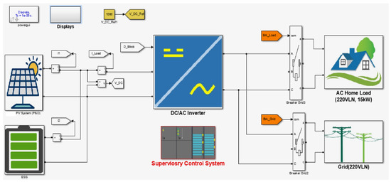
Figure A1.
Dynamic modeling of the system configuration.
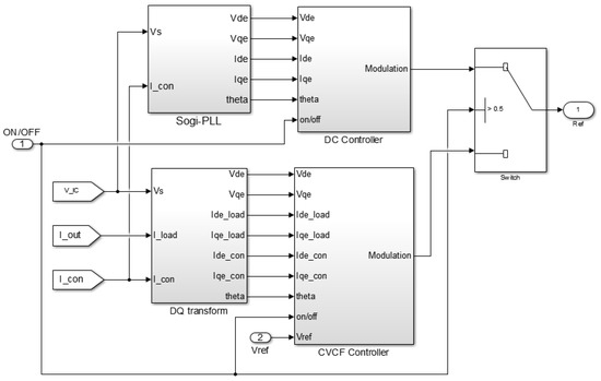
Figure A2.
Control block diagram of the AC/DC interlinking converter.
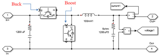
Figure A3.
Bidirectional DC/DC converter.
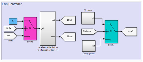
Figure A4.
Control block diagram of the ESS.
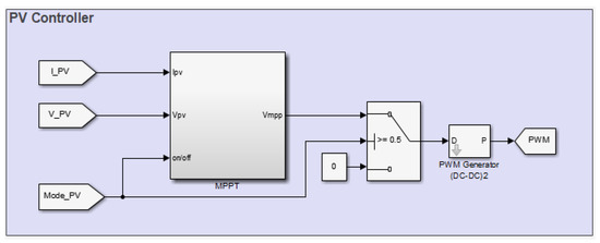
Figure A5.
Control block diagram of the PV.
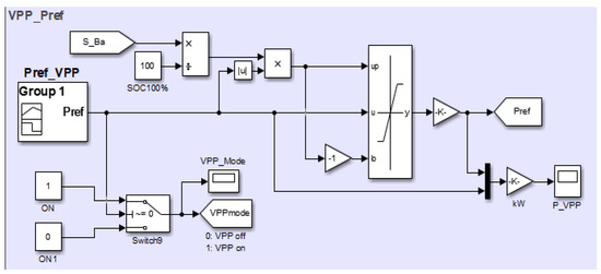
Figure A6.
Block diagram of the VPP simulator.
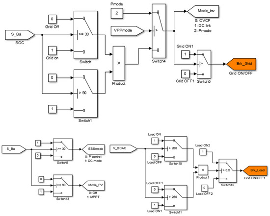
Figure A7.
Concise block diagram of the supervisory power coordination.
References
- Patterson, P.T. Dc, come home: Dc microgrids and the birth of the “enernet”. IEEE Power Energy Mag. 2012, 10, 60–69. [Google Scholar] [CrossRef]
- Zhang, L.; Liang, J.; Tang, W.; Li, G.; Cai, Y.; Sheng, W. Converting AC distribution lines to DC to increase transfer capacities and DG penetration. IEEE Trans. Smart Grid 2018, 10, 1477–1487. [Google Scholar] [CrossRef]
- Wu, T.F.; Chang, C.H.; Lin, L.C.; Yu, G.R.; Chang, Y.R. DC-bus voltage control with a three-phase bidirectional inverter for DC distribution systems. IEEE Trans. Power Electron. 2013, 28, 1890–1899. [Google Scholar] [CrossRef]
- Nguyen, T.T.; Yoo, H.J.; Kim, H.M. A comparison study of MVDC and MVAC for deployment of distributed wind generations. In Proceedings of the 2016 IEEE International Conference on Sustainable Energy Technologies (ICSET), Hanoi, Vietnam, 14–16 November 2016; pp. 138–141. [Google Scholar]
- Wang, P.; Goel, L.; Liu, X.; Choo, F.H. Harmonizing AC and DC: A hybrid AC/DC future grid solution. IEEE Power Energy Mag. 2013, 11, 76–83. [Google Scholar] [CrossRef]
- Guerrero, J.M.; Vasquez, J.C.; Matas, J.; De Vicuña, L.G.; Castilla, M. Hierarchical control of droop-controlled ac and dc microgridsła general approach toward standardization. IEEE Trans. Ind. Electron. 2011, 58, 158–172. [Google Scholar] [CrossRef]
- Guerrero, J.M.; Chandorkar, M.; Lee, T.L.; Loh, P.C. Advanced control architectures for intelligent microgrids, part i: Decentralized and hierarchical control. IEEE Trans. Ind. Electron. 2013, 60, 1254–1262. [Google Scholar] [CrossRef] [Green Version]
- Mahmood, H.; Michaelson, D.; Jiang, J. Accurate reactive power sharing in an islanded microgrid using adaptive virtual impedances. IEEE Trans. Power Electron. 2015, 30, 1605–1617. [Google Scholar] [CrossRef]
- Bidram, A.; Davoudi, A.; Lewis, F.L. A multiobjective distributed control framework for islanded ac microgrids. IEEE Trans. Ind. Inform. 2014, 10, 1785–1798. [Google Scholar] [CrossRef]
- Nasirian, A.; Shafiee, Q.; Guerrero, J.; Lewis, F.; Davoudi, A. Droopfree distributed control for ac microgrids. IEEE Trans. Power Electron. 2016, 31, 1600–1617. [Google Scholar] [CrossRef] [Green Version]
- Guo, F.; Wen, C.; Mao, J.; Song, Y.D. Distributed secondary voltage and frequency restoration control of droop-controlled inverterbased microgrids. IEEE Trans. Ind. Electron. 2015, 62, 4355–4364. [Google Scholar] [CrossRef]
- Bidram, A.; Davoudi, A.; Lewis, F.L.; Guerrero, J.M. Distributed cooperative secondary control of microgrids using feedback linearization. IEEE Trans. Power Syst. 2013, 28, 3462–3470. [Google Scholar] [CrossRef] [Green Version]
- Sun, Q.; Han, R.; Zhang, H.; Zhou, J.; Guerrero, J. A multiagent-based consensus algorithm for distributed coordinated control of distributed generators in the energy internet. IEEE Trans. Smart Grid 2015, 6, 3006–3019. [Google Scholar] [CrossRef] [Green Version]
- Schiffer, J.; Seel, T.; Raisch, J.; Sezi, T. Voltage stability and reactive power sharing in inverter-based microgrids with consensusbased distributed voltage control. IEEE Trans. Control Syst. Technol. 2016, 24, 96–109. [Google Scholar] [CrossRef] [Green Version]
- Shafiee, Q.; Guerrero, J.M.; Vasquez, J.C. Distributed secondary control for islanded microgridsła novel approach. IEEE Trans. Power Electron. 2014, 29, 1018–1031. [Google Scholar] [CrossRef] [Green Version]
- Lu, L.Y.; Chu, C.C. Consensus-based droop control synthesis for multiple dics in isolated micro-grids. IEEE Trans. Power Syst. 2015, 30, 2243–2256. [Google Scholar] [CrossRef]
- Simpson, J.W.; Orfler, M.P.; Bullo, F. Synchronization and power sharing for droop-controlled inverters in islanded microgrids. Automatica 2013, 49, 2603–2611. [Google Scholar] [CrossRef] [Green Version]
- Wu, X.; Shen, C.; Iravani, R. Feasible range and optimal value of the virtual impedance for droop-based control of microgrids. IEEE Trans. Smart Grid 2016, 8, 1242–1251. [Google Scholar] [CrossRef]
- Li, Y.W.; Kao, C.N. An accurate power control strategy for power-electronics-interfaced distributed generation units operating in a low-voltage multibus microgrid. IEEE Trans. Power Electron. 2009, 24, 2977–2988. [Google Scholar]
- O’Shaughnessy, E.; Cruce, J.R.; Xu, K. Too much of a good thing? Global trends in the curtailment of solar PV. Sol. Energy 2020, 208, 1068–1077. [Google Scholar] [CrossRef] [PubMed]
- Pollefliet, J. Power Electronics: Switches and Converters, 1st ed.; Academic Press: Cambridge, MA, USA, 2018. [Google Scholar]
- Ko, H.S.; Jang, M.S.; Ryu, K.S.; Kim, D.J.; Kim, B.K. Supervisory Power Quality Control Scheme for a Grid-Off Microgrid. IEEE Trans. Sustain. Energy 2017, 9, 1003–1010. [Google Scholar] [CrossRef]
- Perez, G.; Gandiaga, I.; Garmendia, M.; Reynaud, J.F.; Viscarret, U. Modelling of Li-ion batteries dynamics using impedance spectroscopy and pulse fitting: EVs application. World Electr. Veh. J. 2013, 6, 644–652. [Google Scholar] [CrossRef] [Green Version]
- The Math-Works Inc. Matlab/Simulink Toolbox; The Math-Works Inc.: Natick, MA, USA, 2016. [Google Scholar]
Publisher’s Note: MDPI stays neutral with regard to jurisdictional claims in published maps and institutional affiliations. |
© 2021 by the authors. Licensee MDPI, Basel, Switzerland. This article is an open access article distributed under the terms and conditions of the Creative Commons Attribution (CC BY) license (https://creativecommons.org/licenses/by/4.0/).