Abstract
This paper studies the dynamics of a two-stage gear transmission system in both the normal state and the fault state with tooth breakage. The torsional vibration model of the two-stage parallel shaft gear was developed by using the lumped parameter method. The time-varying meshing stiffness of the gear transmission system is described by Fourier series which is determined by the periodical meshing characteristics of the gears with both the single-tooth and the double-tooth contacts. By introducing the pulse into the regular time-varying meshing stiffness, the tooth breakage existing in the gear transmission system is mimicked. Based on the numerical simulation of the developed dynamic model, both the time domain analysis and the frequency domain analysis of the gear transmission system under both the normal condition and the tooth breakage are compared accordingly. The influence of the tooth breakage on the dynamic characteristics of the gear transmission system is analyzed comprehensively. Furthermore, based on the developed test bench of a two-stage gear transmission system, the experimental research was carried out, and the experimental results show great agreements with the results of numerical simulation, and thus the validity of the developed mathematical model is demonstrated. By comparing the periodic motion with the chaotic motion, the fault identification for the gear transmission system is verified to be tightly related to its vibration condition, and the control of the vibration condition of the gear transmission system as periodic motion is of great significance to the fault diagnosis.
1. Introduction
The gear transmission system is a key component of wind turbines, aircraft engines and other equipment. The gear transmission system usually works in a high-load, high-speed operating state for a long period, under such a circumstance, gears are easily damaged under the interaction between the fatigue loads and other random factors. Once the gear fails, the transmission system is affected immediately, and thus the safety of the equipment, which can even trigger serious safety accidents and major property losses. Therefore, the research of the vibration characteristics of the gear transmission system is carried out to quickly and accurately identify the faults in the gearbox, which is essential to ensure the stable operation of the gear transmission system.
The gear transmission system transmits power and movement through the meshing of gear pairs, which includes a series of nonlinear factors during the meshing process: time-varying meshing stiffness, meshing error, meshing phase of different tooth pairs, tooth side clearance, friction and wear, etc. [1]. As the first step, the developed model was a linear time-invariant model; specifically, the time-varying meshing stiffness was replaced by the average stiffness, and the internal excitation caused by the time-varying meshing stiffness was ignored, as well as the mutual influence and internal excitation during multi-tooth meshing were also ignored. Kahraman [2] proposed a dynamic torsion model of single-stage planetary gear transmission. Wang et al. [3] established a torsion model of 2K-H uniformly distributed planetary gear transmission. Aiming at studying the error excitation, Yuan [4] established a multi-degree-of-freedom model of the planetary reducer, derived the dynamic differential equation of the vibration system, and analyzed the interaction influences of the meshing stiffness of the gear pair and the excitation of the meshing error. Vinayak et al. [5] studied the influence of meshing error on the dynamics of the single-stage gear system. Sun [6] analyzed a closed planetary gear transmission system. Wang [7] studied the dynamic characteristics of a gear system by considering the time-varying stiffness of gear teeth and the static transfer error excitation by using the multi-scale method. Liu et al. [8] established a single-stage gear system whose clearance is a piecewise linear function and studied the influence of system parameter on the nonlinear behavior of the system. Kahraman et al. [9] studied nonlinear factors fora spur gear pair and received the internal excitation of the gear. Ji [10] established a two-stage gear transmission system considering multiple nonlinear factors. In addition, Sun et al. [11,12] constructed a multi-degree-of-freedom nonlinear torsional vibration model of a planetary gear transmission system, and their study found that the increase of the gear gap will affect the meshing state of the gear pair. Tian [13] used the time-varying meshing stiffness as input excitation to obtain the dynamic responses of the gear transmission system. Zhou [14] comprehensively analyzed the influence of the machining error, assembly error, gear meshing time-varying stiffness and clearance of each part on the uniform load performance of the planetary gear. Qian et al. [15] used Lagrangian equations to establish a 2K-H planetary gear train translation-torsional coupling vibration model, while Zhu [16] established a 2K-H planetary gear translation-torsional coupling vibration model that considered friction, time-varying meshing stiffness, tooth backlash and comprehensive meshing error.
However, in the actual operation of the gear transmission system, various faults are always unavoidable, which affect the stable operation of the gear transmission system. Thus, it is necessary to study the mechanism of failure and its impacts on the gear transmission system. A large number of scholars have conducted studies on the dynamics of gear transmission systems with various faults. Choy et al. [17] conducted numerical and experimental research on gear transmission systems with tooth surface pitting, wear and partial tooth-breaking faults. An et al. [18] used ANSYS to simulate the influence of tooth surface pitting and spalling on the meshing stiffness of the system, and the results showed that these faults reduced the meshing stiffness. Kang and Lin [19] studied the influence of the surface wear of spur gears on the change of the frequency spectrum. Chari et al. [20,21] considered the effect of gear cracks on the meshing stiffness, and compared the differences between the normal and the faulty conditions in both the time domain and the frequency domain. Panrey et al. [22,23] established a dynamic model with multiple faults, and analyzed the corresponding response signals. Wang et al. [24,25] developed a single-stage gear model for shock analysis. Ning et al. [26] studied the effect of tooth root cracks. Wu et al. [27] discussed the effect of crack degree on gear meshing stiffness and analyzed the evolution mechanism of cracks. Zhang et al. [28] conducted corresponding research on the gear dynamic model with fatigue cracks, and the results showed that the greater the load of the gearbox, the more obvious the fault characteristics. Su et al. [29] found that the gear speed and tooth surface friction factor played a major role in the influence of the vibration of gear transmission system. Wang et al. [30] studied the crack propagation of spur gears and the effect of crack propagation on the time-varying meshing stiffness. Wang et al. [31] studied the nonlinear dynamic characteristics of a single-stage gear system with wear faults. Gao et al. [32] found that the gear system’s transmission error, vibration shock state and vibration severity varied with the degree of wear on tooth surface. For the feature extraction of rolling bearing faults, based on variational modal decomposition and singular value decomposition, Liu et al. [33] proposed a method to accurately extract fault features from vibration signals. Li et al. [34] used empirical wavelet transform to extract the modulation components in the frequency spectrum of rubbing fault signal. Yuan et al. [35] used the Hidden Markov model to diagnose multiple types of faults for gearbox shaft. Zhu and Feng et al. [36] used an improved empirical wavelet transform method, combining empirical mode decomposition and wavelet transform, to successfully realize the demodulation of vibration signals. Xu et al. [37] proposed a wavelet correlation filtering method based on the characteristics of wavelet correlation filtering, combined with envelope spectrum analysis, and successfully achieved the extraction of early fault information of gearbox bearings under the influence of strong background noise. Zhang et al. [38] combined multifractal and approximate entropy, and used subtractive clustering and fuzzy C-means clustering to process vibration signals and successfully extracted gearbox fault features. Munro [39] discovered the phenomenon of amplitude jumping, multiple solutions, and irregular motion (chaotic motion) in the gear system in experimental research. Kahraman [40] found the abundant nonlinear phenomena of the gear transmission system through a self-designed test rig. Via the comparison of experiments and finite element methods, Kubur [41] found a number of factors that have important effects on the dynamic responses of the gear transmission system.
Based on the aforementioned literature review, in order to study the nonlinear vibration characteristics and fault mechanism of the gear transmission system, this paper combines the theoretical modeling and the experimental testing, and introduces the fault feature into the dynamic model of the gear transmission system, and analyzes its nonlinear dynamic characteristics. This is beneficial for better understanding the operation state of the gear transmission system, realizing the early fault prediction and identification for the transmission system.
2. Mathematical Modeling
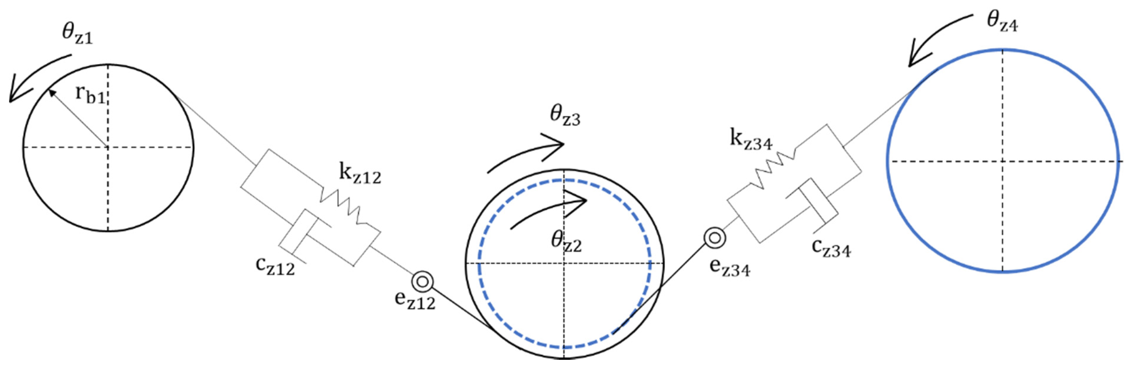
A two-stage gear transmission system consists of two pairs of meshing gears, all of which are spur gears. Ignoring the lateral vibration between the gears, the torsional vibration model of the two-stage gear transmission system is shown in Figure 1. Specifically, and represent the meshing stiffness for gear 1 and gear 2, gear 3 and gear 4, respectively; and represent the meshing damping for gear 1 and gear 2, gear 3 and gear 4, respectively; and represent the meshing errors for gear 1 and gear 2, gear 3 and gear 4, respectively; (i = 1, 2, 3, 4) represents the torsion angular displacement for each gear.
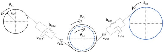
Figure 1.
Torsional vibration model of a two-stage gear transmission system.
2.1. Dynamic Model
The lumped parameter method is used to develop the dynamic model of the two-stage gear transmission system based on the consideration of time-varying meshing stiffness, comprehensive meshing error, and tooth side clearance as
where (i = 12,34) is the moment of inertia for gear; and are the meshing forces for gear 1 and gear 2, gear 3 and gear 4, respectively; and are the relative displacements on the meshing lines of each gear. Specifically
The nonlinear function of gear backlash is defined as (i = 12,34) as
where (i = 12,34) is half of the tooth flank clearance. Therefore, the Equation (1) can be further simplified as
where ,, are the equivalent mass of the gear, which can be expressed as , , .
Defining the time scale as , then the dimensionless time ; in addition, the dimensionless displacement can be set as (i = 1,2); hence, the dimensionless nonlinear function of gear backlash can be set as
Therefore, Equation (3) can be further dimensionalized as
where (i = 1,2) is the dimensionless excitation frequency, and (i = 1,2) is the dimensionless time-varying stiffness , and .
2.2. Time-Varying Stiffness
The gears studied in this work are all straight cylindrical gears. In the process of gear meshing, there will be both single-tooth meshing and double-tooth meshing. In the case of continuous rotation of the gear, the meshing stiffness of the gears will show periodic changes with the continuous alternation between the single-tooth meshing and double-tooth meshing. When only a pair of gears bear the load, and the elastic deformation of the gear pair is large, the comprehensive meshing stiffness of the gears is small. While two pairs of gears are meshed, the elastic deformation of the gear pairs is small, and the meshing comprehensive stiffness is large, hence the gear teeth meshing has obvious step mutations. According to the gear meshing frequency, the gear’s comprehensive meshing stiffness can be simplified as a periodic function of a rectangular wave. Finally, it is expanded as a Fourier series, and the first harmonic term is generally used as the time-varying meshing stiffness of the gear for numerical simulation.
where is the average meshing stiffness of the i-th gear pair; is the change amplitude of the meshing stiffness for the i-th gear pair; is the meshing frequency of the i-th gear pair; is the initial phase angle for the meshing stiffness change of the i-th gear pair.
2.3. Model for Tooth Breakage
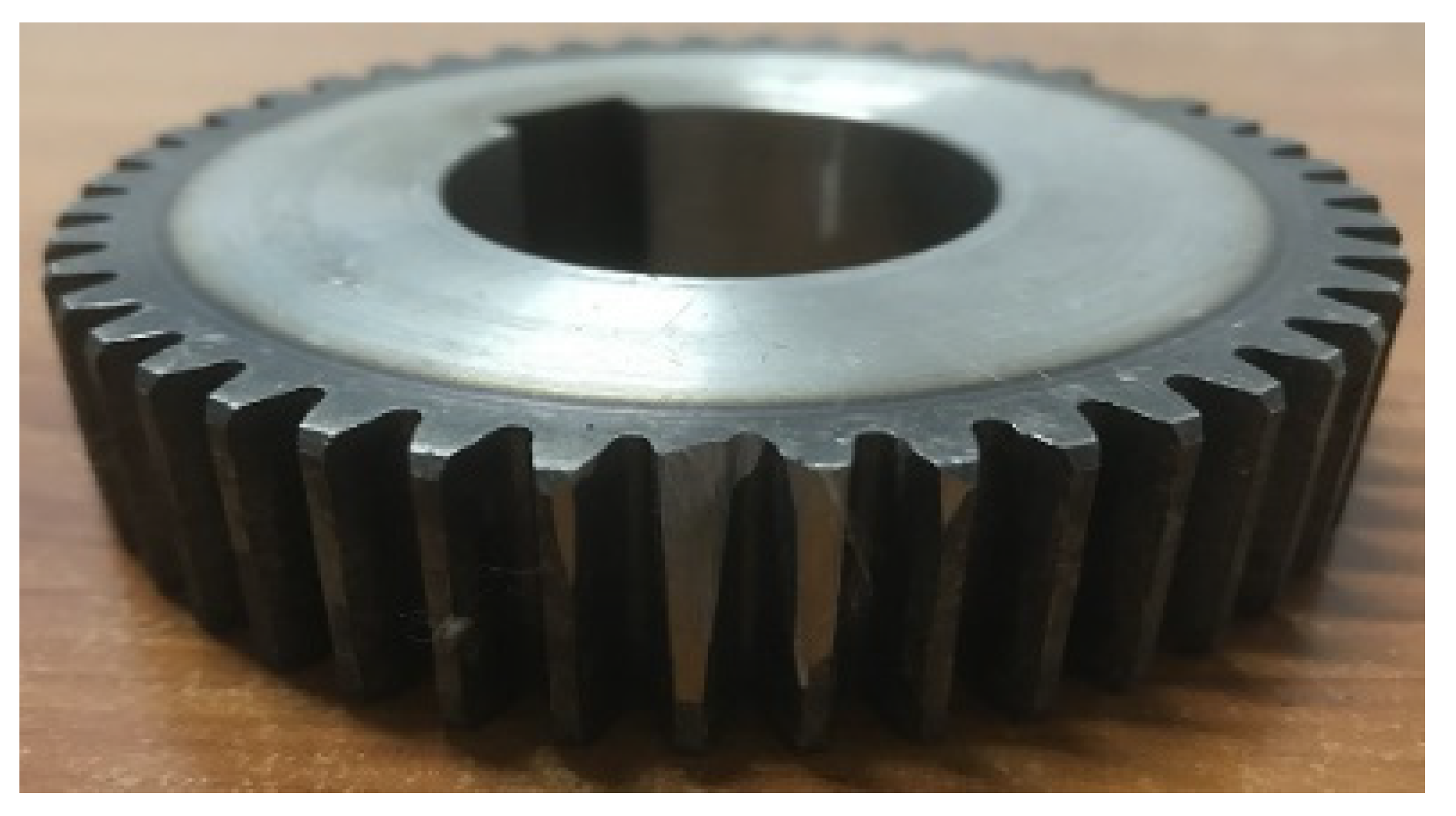
When tooth breakage occurs on single tooth surface of a gear, it will cause the gear to generate a positive meshing impact signal when the tooth is meshed, which will weaken the stiffness of the broken tooth. In order to study this phenomenon, the broken tooth is assumed as belonging to the part of the middle-speed pinion. The gear shown in Figure 2 is a middle-speed pinion with partial broken teeth which will be tested experimentally.

Figure 2.
Partially broken mid-speed pinion gear.
Moreover, is applied to represent the broken tooth fault, where represents the degree of broken tooth, and is a periodic continuous pulse function with a unit amplitude. According to the periodicity of gear meshing, the frequency of the fault shock signal is equal to the rotation frequency of the faulty gear, and the pulse width is the gear meshing period. By considering Equation (7), the time-varying meshing stiffness with failure can be obtained as
k′(t) = k(t) – αδ(t)
2.4. Meshing Error of Gear Pair
The comprehensive meshing error of gears can be regarded as a displacement excitation, which is generally determined according to the initial design grade, and a harmonic function is used to describe the error mathematically as
where is the constant value of the comprehensive meshing error of a gear pair; is the amplitude of the comprehensive meshing error of the i-th gear pair; is the rotational angular velocity of the i-th gear pair; is the initial phase angle for the i-th gear pair.
3. System Parameters
As a prerequisite for the simulation solution based on the developed dynamic model, the parameters for the gear transmission system need to be determined, which mainly include the geometric parameters of the gear transmission system and a series of structure parameters.
3.1. Geometric Parameters
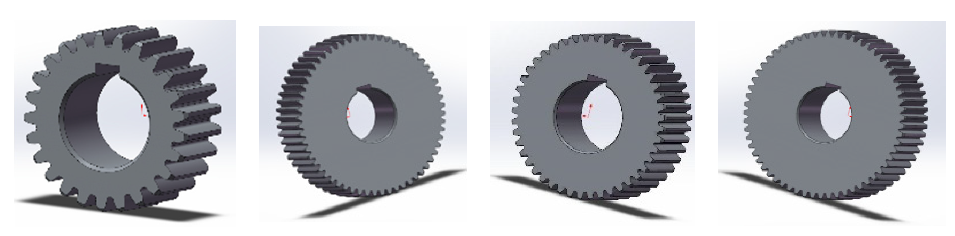
Compared with the experimental device that will be introduced later, the geometric parameters of each gear are listed in Table 1. Moreover, in order to obtain the moment of inertia of each gear, SolidWorks was used to establish the three-dimensional models for all the gears of the two-stage gear transmission system, as shown in Figure 3.

Table 1.
Geometric parameters of gear transmission system.

Figure 3.
Three-dimensional models of the four gears of the two-stage gear system.
3.2. Structure Parameters
Primarily, the finite element method is used to calculate the meshing stiffness of each gear . Specifically, the geometric model established by SolidWorks is introduced into Abaqus, the gear tooth is simplified as an elastic cantilever beam, and an example of the calculation result is shown in Figure 4. In addition, the meshing damping between gear pairs can be solved using empirical calculation formulas [42] as ,where is the gear meshing damping ratio, generally 0.03–0.17, hence 0.1 is used in this work; Rp, Rg are the radius of the base circle of the driving and driven gears, respectively; Ip, Ig are the moment of inertia of the driving and driven gears, respectively; km is comprehensive meshing stiffness of the gear pair. Finally, assuming that the initial phase angle is 0 and the design of the gear is the 8th grade, the comprehensive meshing error parameters of the gear pair can be determined. In summary, the key calculation parameters of the gear transmission system finally obtained are shown in Table 2.
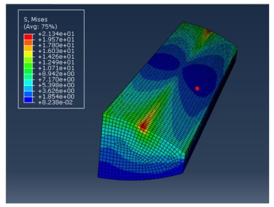
Figure 4.
Von Mises stress cloud diagram of single tooth (MPa).
Table 2.
Structure parameters.
4. Numerical Simulation
Based on the mathematical model developed in Section 2 and the system parameters identified in Section 3, the numerical simulation of the gear transmission system can be carried out subsequently.
4.1. Bifurcation Analysis
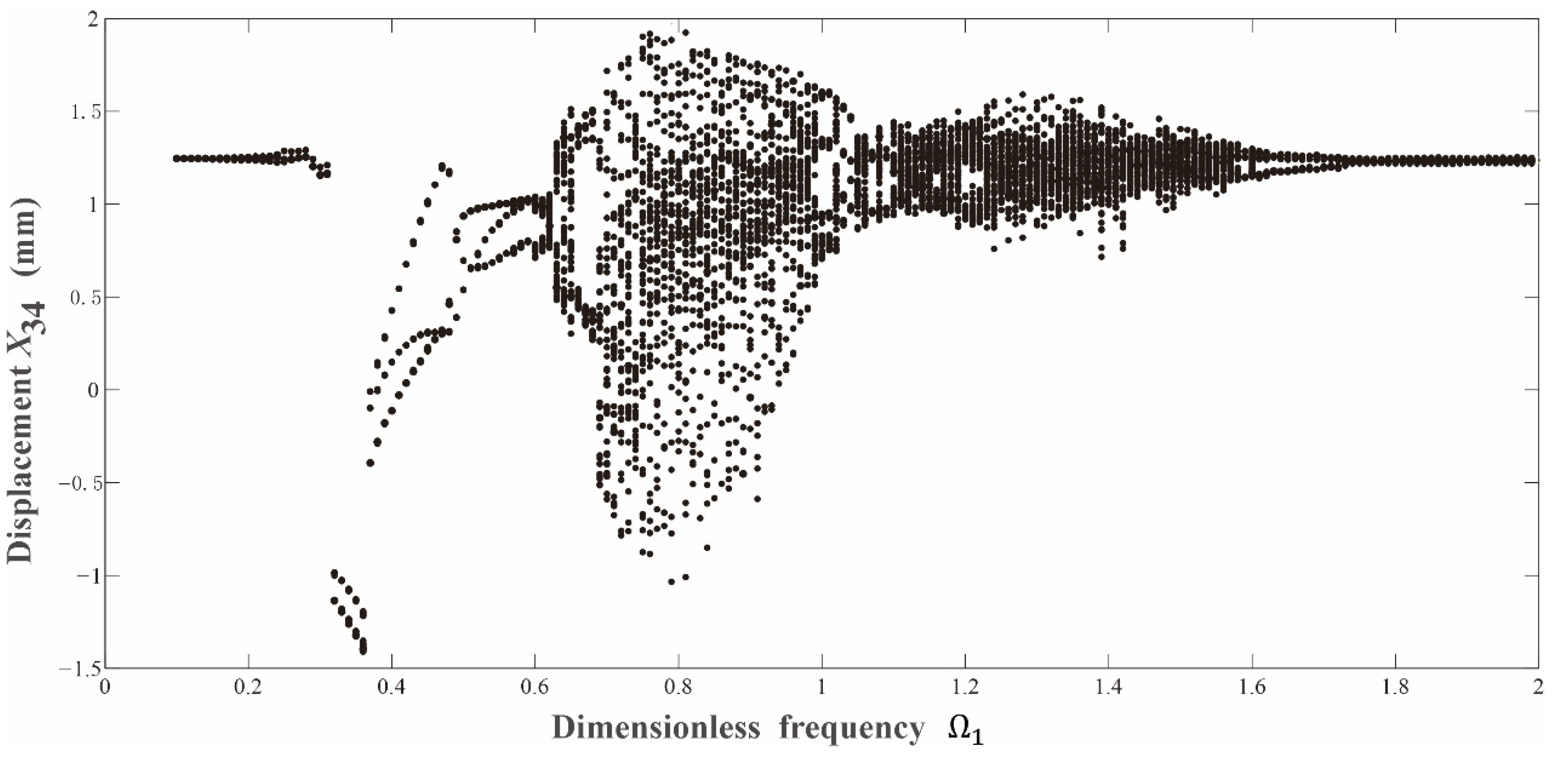
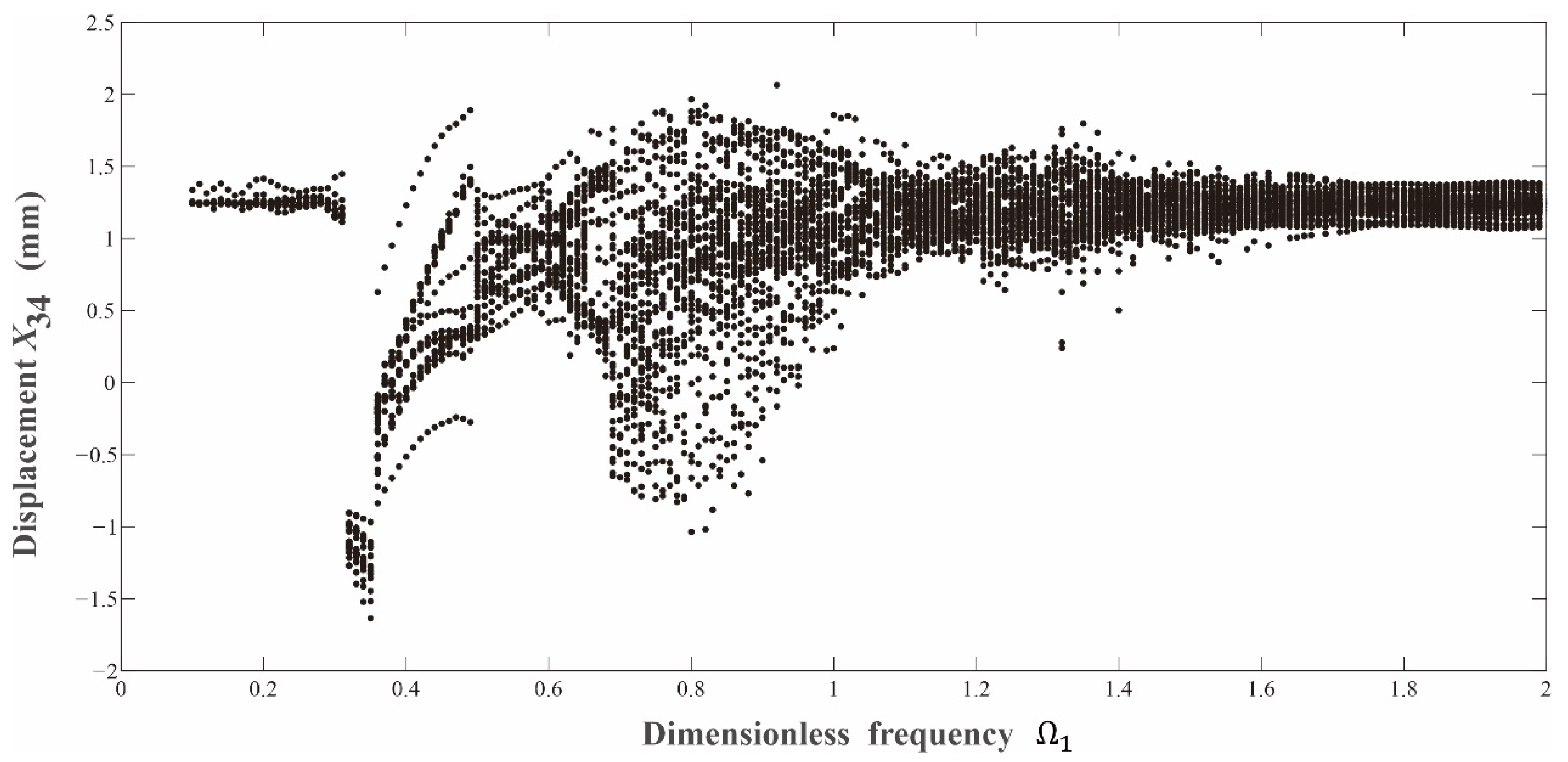
The variable-step Runge–Kutta method was used to solve the corresponding differential equations numerically for the gear transmission system. Primarily, in order to get a comprehensive understanding of the dynamic evolution law of the gear transmission system for both the normal or the fault conditions, their bifurcation diagrams were depicted and compared. Based on the comparison between Figure 5 and Figure 6, it can be seen that the basic structure of the bifurcation diagram for the medium-speed pinion in the fault state with tooth breakage is similar to that for the normal state. Their key difference comes from the numbers of cycles for the system’s periodic motions. Specifically, when compared with the system’s normal state, its fault state with the same system parameters triggers more complicated periodic motions. In addition, when the system enters into chaotic states, the vibration amplitude for the fault state is also greater than that for the normal state.
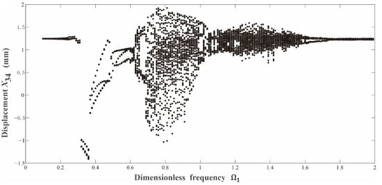
Figure 5.
Bifurcation diagram for the gear transmission system in its normal state.
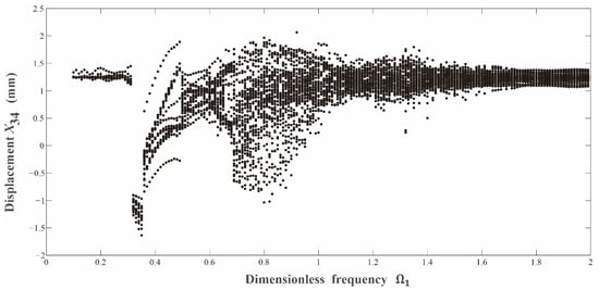
Figure 6.
Bifurcation diagram for the gear transmission system in its fault state.
4.2. Time-Frequency Characteristics
In order to further understand the influences of the tooth breakage on the dynamic responses of the gear transmission system, the phase portraits for the time domain analysis and the frequency spectrums for the frequency domain analysis are depicted for detailed comparison.
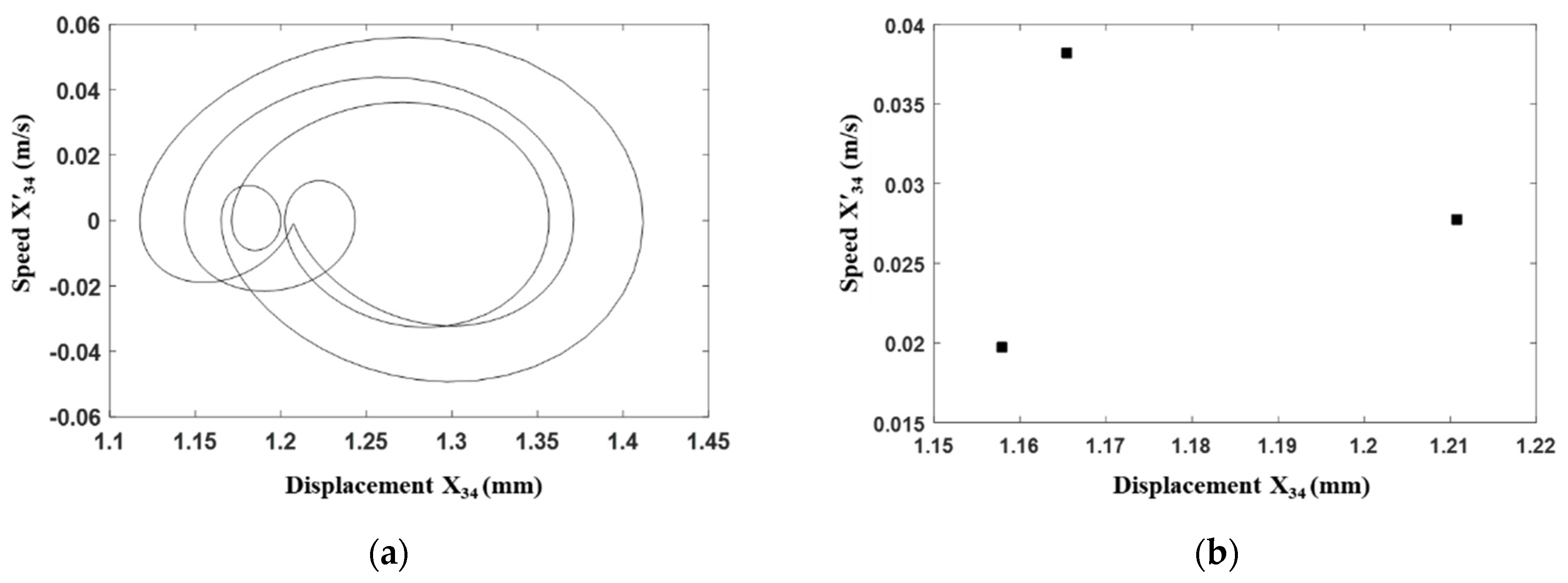
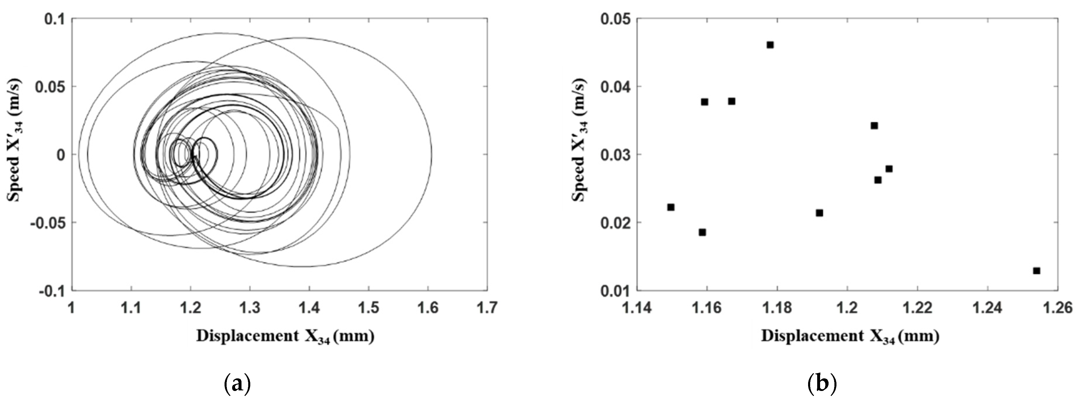
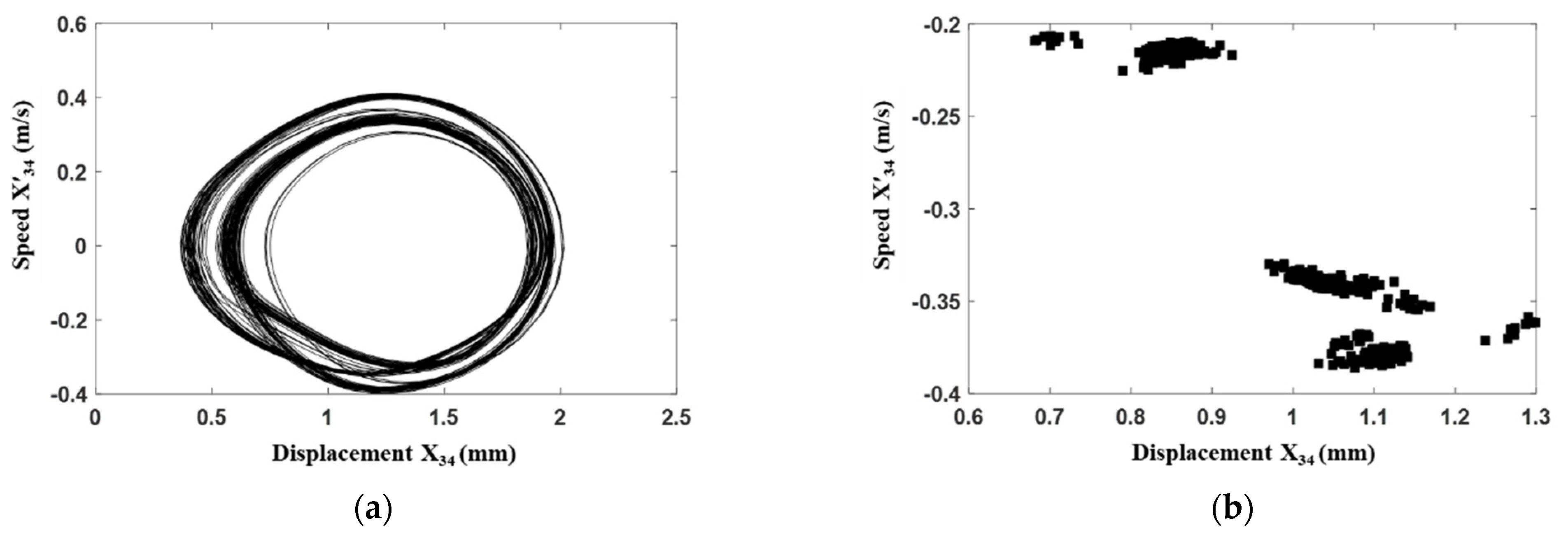
Primarily, the time domain analysis is conducted. It can be seen from Figure 7 for the time domain analysis of the gear transmission system under its normal condition, when the excitation frequency 0.31, a non-circular closed curve appears on the phase portrait, and the Poincarémap displays three discrete points, hence, such avibration condition is a three-period motion. However, as shown in Figure 8, when the middle-speed pinion has the fault as tooth breakage, due to the impact of the broken tooth pulse, the phase portrait under the same excitation frequency becomes a more complicated closed curve with a wider range than that for the normal state; and its Poincarémap changed from three discrete points to ten discrete points, namely, the corresponding vibration condition becomes the ten-period motion.
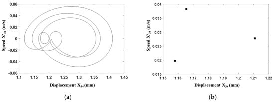
Figure 7.
Time domain analysis of the gear transmission system under its normal condition with . (a) Phase portrait. (b) Poincaré map.
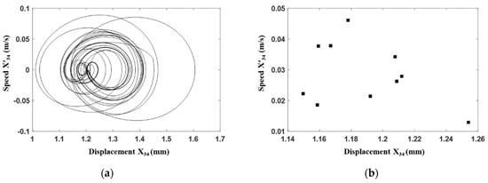
Figure 8.
Time domain analysis of the gear transmission system under the fault condition with . (a) Phase portrait. (b) Poincaré map.
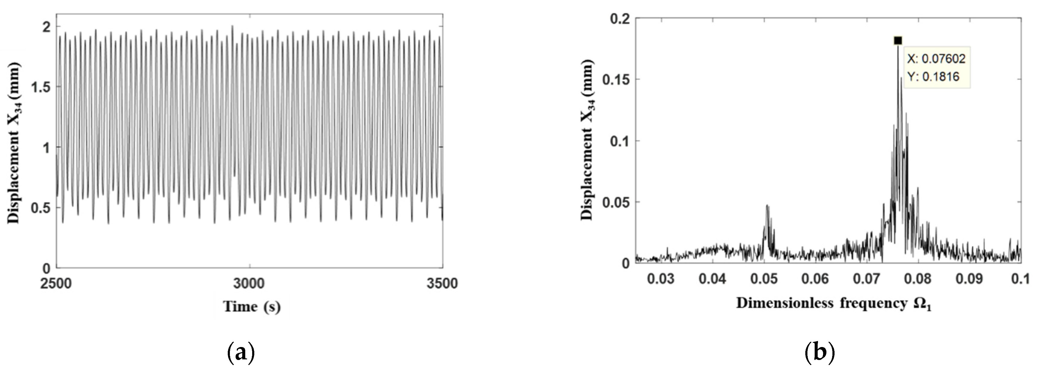
Subsequently, the frequency domain analysis was carried out. The relative displacement between the gear 3 and the gear 4 is shown in Figure 9a for the normal state of the gear transmission system with the dimensionless excitation frequency for the first-stage gear 0.31, thus the corresponding dimensionless excitation frequency for the second-stage gear can be calculated as 0.233, andthe corresponding dimensionless meshing frequency 0.035. Moreover, from the frequency spectrum shown Figure 9b, it can be seen that the main frequency for such a vibration condition is just the meshing frequency . Furthermore, the amplitude of the n/3 (n is an integer) multiple of the main meshing frequency is obviously large, which further demonstrates the three-period characteristics for the corresponding vibration condition.
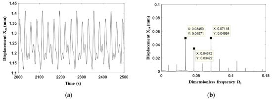
Figure 9.
Frequency domain analysisof the gear transmission system under its normal condition with . (a) Time series. (b) Frequency spectrum.
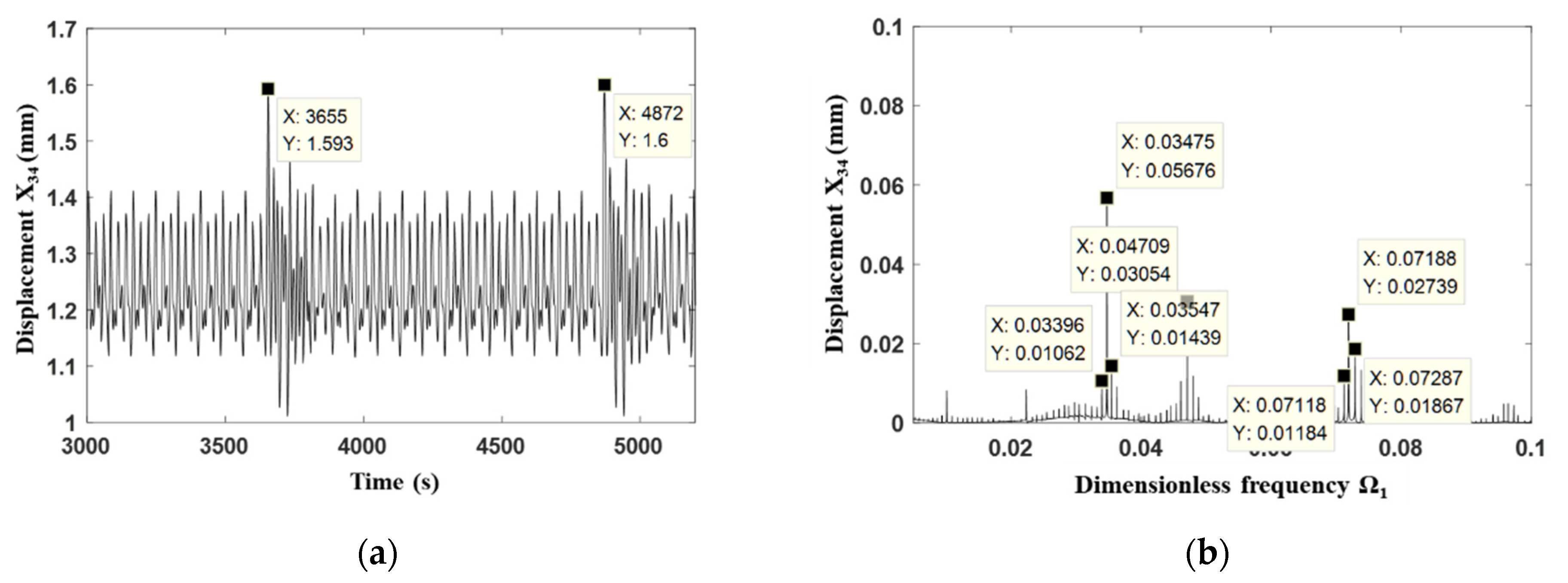
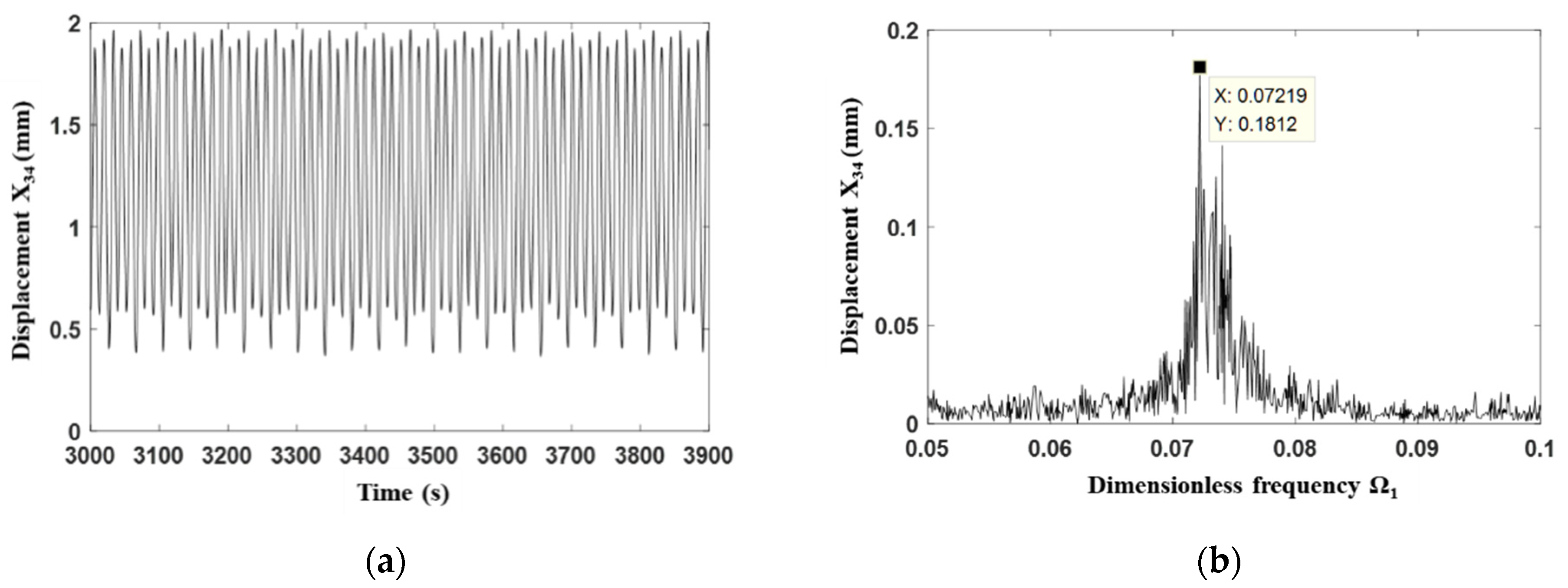
Comparatively, when the gear has the fault with broken tooth, the time series shows pulse fluctuations (see Figure 10a), indicating that the broken tooth is meshing at that time. In addition, it can be seen from Figure 10a that the interval between the two pulse peaks is the rotation period of the medium-speed gear. For the frequency spectrum shown in Figure 10b, the amplitudes of the dimensionless main meshing frequency 0.0354 Hz and its double frequency 0.0723 Hz are obviously large, and there are also obvious equally spaced sidebands, which are consistent with the amplitude-frequency characteristics for broken teeth.
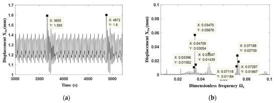
Figure 10.
Frequency domain analysis of the gear transmission system under the fault condition with . (a) Time series. (b) Frequency spectrum.
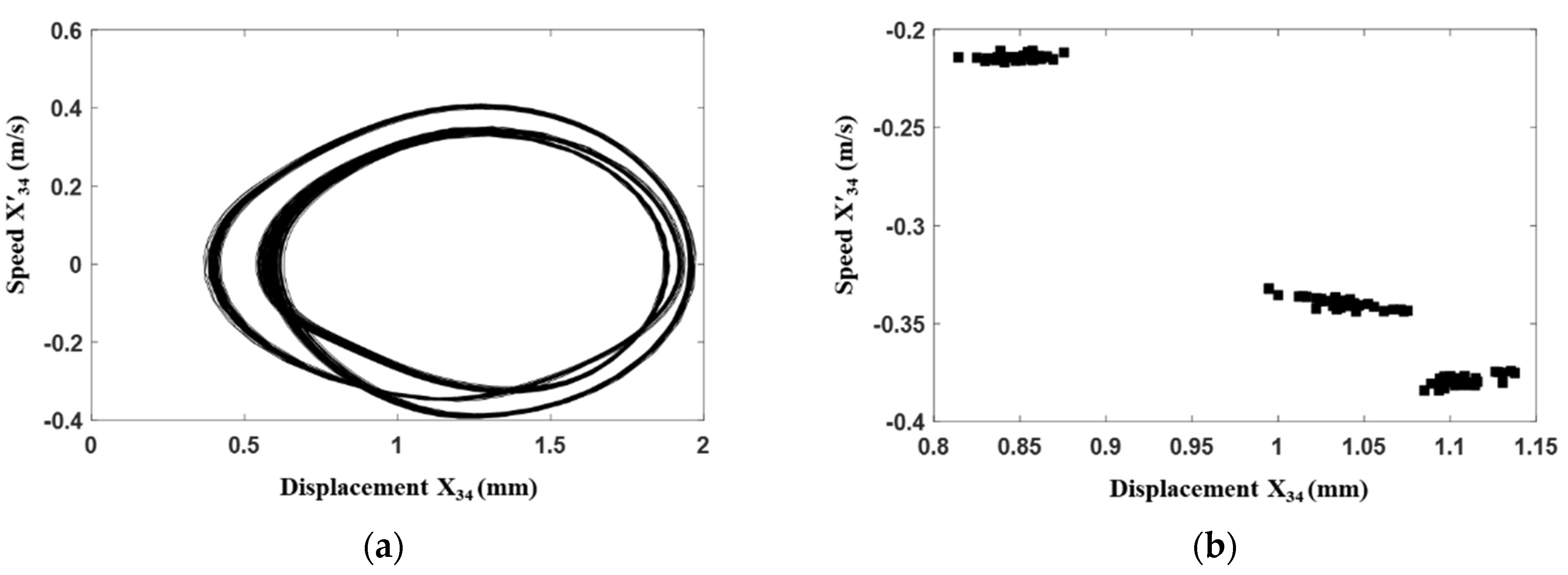
Similarly, the vibration condition for the gear transmission system with the dimensionless excitation frequency for the first-stage gear 0.64 is further discussed. It can be seen from both Figure 11 and Figure 12 that the system enters into chaotic motionsno matter the normal state or the fault state of the gear transmission system. Moreover, when the gear has the fault with the tooth breakage, its motion trajectory is more complicated than that for the normal state.
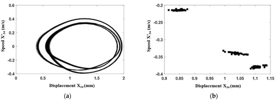
Figure 11.
Time domain analysis of the gear transmission system under its normal condition with . (a) Phase portrait. (b) Poincaré map.
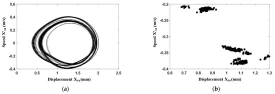
Figure 12.
Time domain analysis of the gear transmission system under the fault condition with . (a) Phase portrait. (b) Poincaré map.
In addition, via the frequency domain analysis as shown in Figure 13 and Figure 14, it can be seen that when the system stays in chaotic motion and the excitation frequency is high, the fault state of the system is not obvious in the frequency domain. Especially, it is difficult to confirm the sidebands in the frequency spectrum, and the time-frequency characteristics are not distinguishing from that of the normal state. On the one hand, when the system stays in chaos for its normal state, the added faults only make its vibration condition more chaotic, and it is hard to find out the fault pulse in the time domain signal. On the other hand, due to the high excitation frequency, the short meshing period decreases the duration of the fault impact, and thus the fault pulse in the time domain signal is difficult to be identified effectively. Under such circumstances, in order to better monitor the operation of the gear transmission system, the parameter ranges of excitation frequency for chaotic motion should be avoided, and the stable periodic motion is ideal for the gear transmission system.
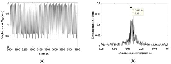
Figure 13.
Frequency domain analysis of the gear transmission system under its normal condition with . (a) Time series. (b) Frequency spectrum.
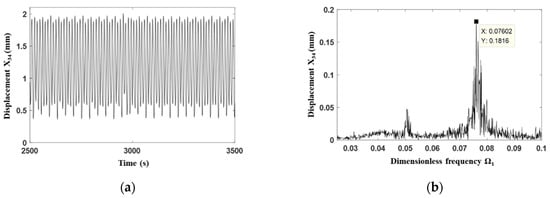
Figure 14.
Frequency domain analysis of the gear transmission system under the fault condition with . (a) Time series. (b) Frequency spectrum.
5. Experimental Verification
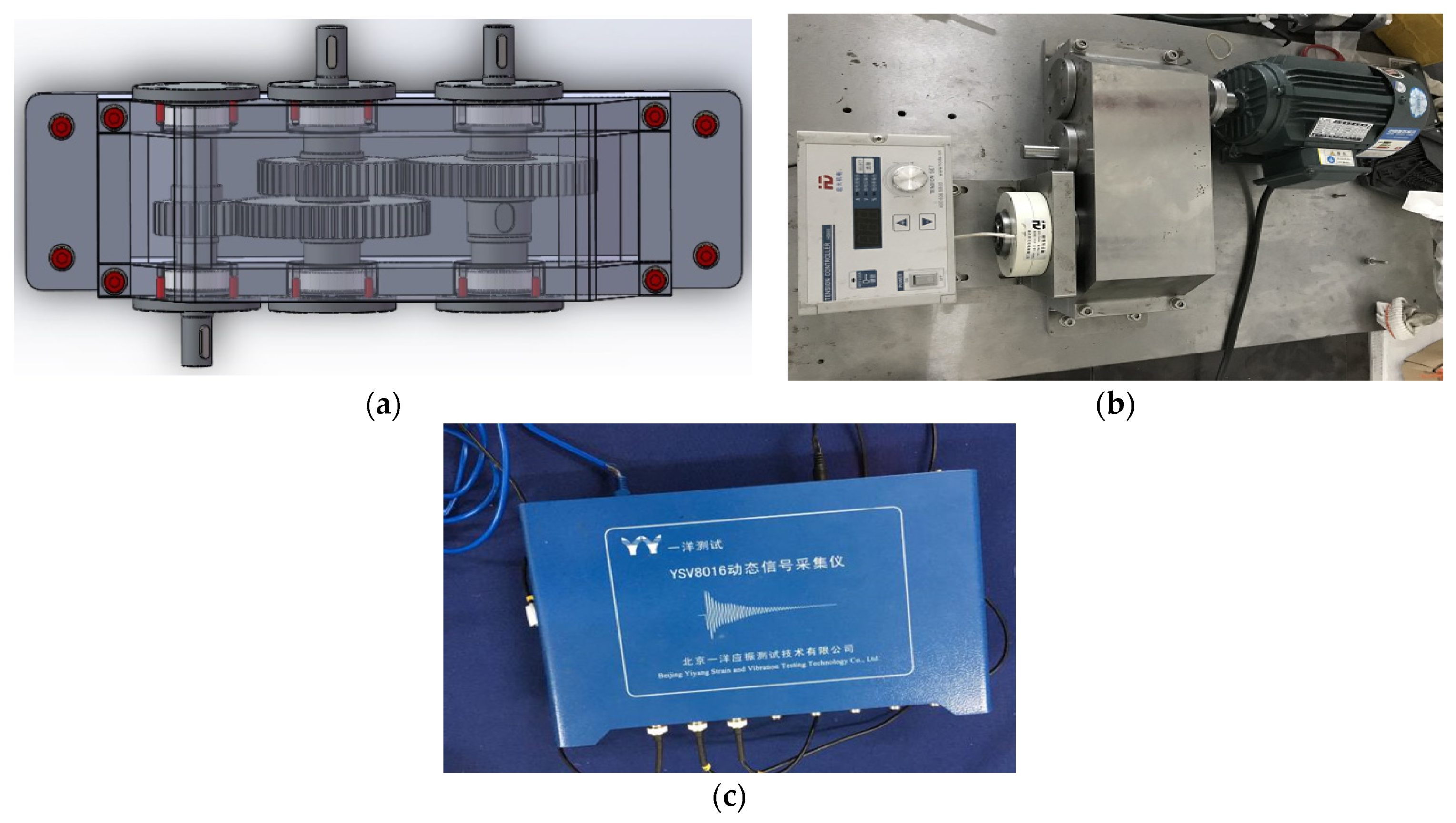
In order to further verify the result of numerical simulation, the corresponding experiment was carried out by using the developed test bench, which is a 0.55 kW two-stage gear transmission system. A load end of this experimental device is equipped with magnetic powder brake, which can generate load by adjusting excitation current. Figure 15 shows the three-dimensional design, the experimental rig for this gear transmission system and the dynamic signal acquisition instrument. During the experimental test, the YA series of three-directional accelerometer was selected, which can collect vibration signals in x, y, and z directions. The advantage of this sensor is that it has a wide range of installation positions and strong flexibility. In this paper, the YSV8016 dynamic signal acquisition instrument was used to convert the analog signal into digital signal, and then the computer records the digital signal to complete the acquisition of the vibration signal. The gearbox bearing seat was selected as the measuring position.
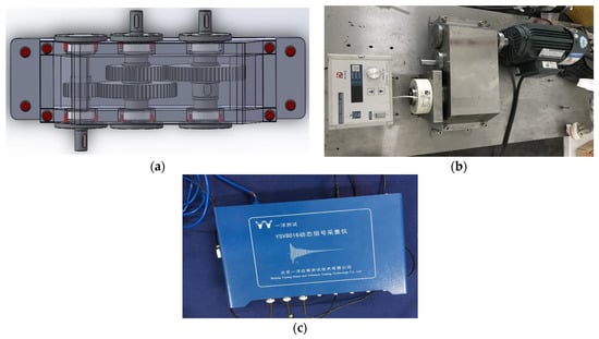
Figure 15.
Experimental set up for the gear transmission system. (a) Three-dimensional design. (b) Experimental rig. (c) YSV8016 dynamic signal acquisition instrument.
This experimental rig can be applied to study the vibration characteristics of the transmission system under different working conditions by changing gears, which is beneficial for the fault diagnosis of the transmission system.
During the experimental test, the gearbox bearing seat was selected as the measuring position, and the sampling frequency was set as 512 Hz with the test duration at 50 s. Since the noise is inevitable for the signals measured via the experiment, the wavelet noise reduction algorithm was also applied [43].
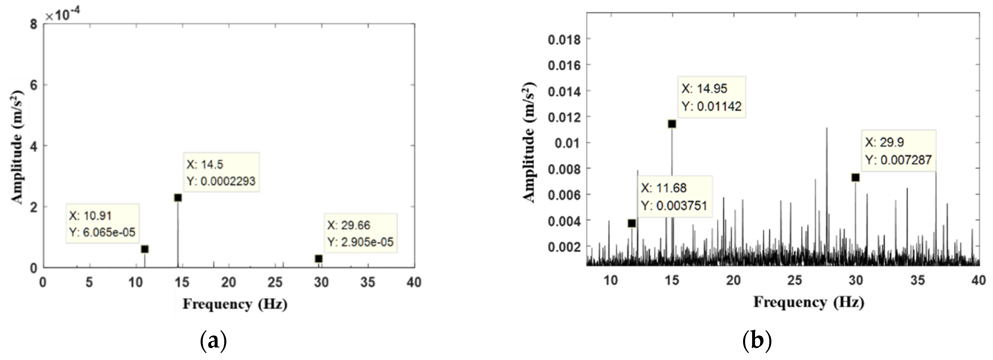
Primarily, the normal state of the gear transmission system was considered. For the experimental test, the rotate speed of the high-speed gear was set as 35 r/min; correspondingly, for numerical simulation, the first-stage gear meshing frequency was14.58 Hz, and the second-stage gear meshing frequency was 10.93 Hz. Under such circumstances, the obtained frequency spectrums of the gear transmission system for both the numerical simulation and the experimental test are shown in Figure 16.
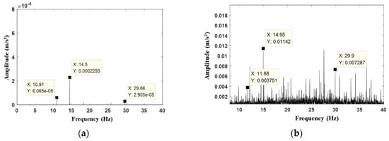
Figure 16.
Comparison of frequency spectrums between numerical and experimental results for normal condition. (a) Numerical result. (b) Experimental result.
As can be observed in Figure 16, the main frequency in the simulated frequency spectrum is 14.5 Hz, which roughly matches the main frequency of 14.95 Hz in the experimental frequency spectrum. Moreover, for the high-speed pinion with rotate speed of 35 r/min, the theoretical meshing frequency is 14.5 Hz. Hence, a great agreement is achieved. The double frequency (29.66 Hz) of the first-stage gear meshing frequency (14.5 Hz) is also observed in the simulated frequency spectrum, comparatively, the double frequency (29.9 Hz) also appeared in the experimental frequency spectrum. In addition, the meshing frequency of the second-stage gear is explored in both the simulated and experimental frequency spectrums, which appears at 10.91 Hz and 11.68 Hz, respectively.
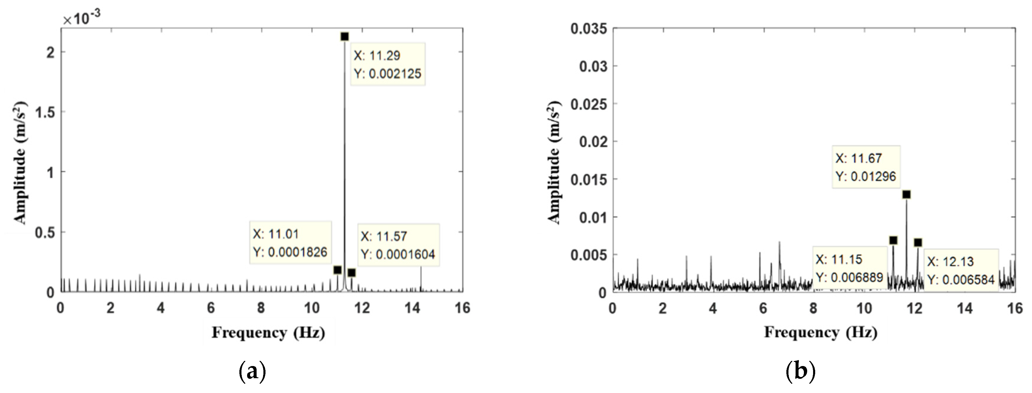
Subsequently, the medium-speed pinion gear was replaced by a gear with tooth breakage as shown in Figure 2, and then the above experimental test was repeated. The simulated and experimental frequency spectrums for the gear transmission system with fault state are shown in Figure 17. The main frequency for numerical result is 11.29 Hz, which roughly matches the main frequency of 11.67 Hz obtained from the experimental frequency spectrum. Numerical simulation shows that the amplitude of the dominant frequency in the fault state (shown in Figure 17a) is higher than that in the normal state (shown in Figure 16a). Furthermore, comparing Figure 17b with Figure 16b, the experimental results also show the same result. Therefore, it can be concluded that the amplitude of the dominant frequency increases when the tooth of gear breaks. In addition, the sidebands with an interval of 0.26 Hz are explored for both the numerical and experimental results, which satisfy the characteristics of the fault with tooth breakage.
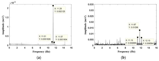
Figure 17.
Comparison of frequency spectrums between numerical and experimental results for fault condition. (a) Numerical result. (b) Experimental result.
Based on the above analyses, it can be concluded that the simulation results of the gear transmission system under both the normal condition and the fault condition are consistent with the experimental results, and thus the developed dynamic model is further verified.
6. Conclusions
In this present work, a dynamic model regarding the torsional vibration for a two-stage gear transmission system was developed by considering the time-varying meshing stiffness, the meshing error, and the nonlinear tooth side clearance simultaneously. The corresponding system parameters were identified according to the built experimental test bench for a 0.55 kW two-stage gear transmission system. The normal state and the fault state with tooth breakage for the medium-speed pinion gear were compared systematically, and thus the influences of the tooth breakage on the dynamic responses of the gear transmission system were discussed. The corresponding experimental test was also carried out, and thus the developed dynamic model was further verified experimentally.
Based on the results of numerical simulation, the two-stage gear transmission system exhibits rich bifurcation scenarios under the influence of time-varying meshing stiffness, tooth backlash and meshing error. Both the periodic motions and the chaos were observed. When compared with the normal state of the gear transmission system, its fault state with the same system parameters triggered more complicated periodic motions. In addition, when the system entered into chaotic states, the vibration amplitude for the fault state was also greater than that for the normal state.
In addition, the fault identification for the gear transmission system is tightly related to its vibration condition. Specifically, the fault characteristics of the system in periodic motion can be conveniently explored from the frequency spectrum, while once the system entered into chaos, the fault characteristics were mixed with the chaotic motion, and it was then hard to find out in the frequency spectrum. Therefore, the control of the vibration condition of the gear transmission system as periodic motions is of great significance to the fault diagnosis.
Author Contributions
Conceptualization, D.F. and S.G.; methodology, S.G.; software, H.L.; validation, D.F. and H.L.; formal analysis, D.F.; investigation, D.F.; resources, S.G.; data curation, H.L.; writing—original draft preparation, D.F.; writing—review and editing, S.G.; visualization, D.F.; supervision, S.G.; project administration, S.G.; funding acquisition, S.G. All authors have read and agreed to the published version of the manuscript.
Funding
This research received no external funding.
Informed Consent Statement
Not applicable.
Data Availability Statement
The datasets generated and analyzed during the current study are available from the corresponding author on reasonable request.
Acknowledgments
Here I would like to thank Shiqiao Gao and Haipeng Liu for their care and support.
Conflicts of Interest
The authors declare that they have no conflict of interest concerning the publication of this manuscript.
References
- Hong, Q.; Cheng, Y. A gear pair model and its application in the software Adams. Acta Armamentaria 2003, 24, 509–512. [Google Scholar]
- Kahraman, A. Natural Modes of Planetary Gear Trains. J. Sound Vib. 1994, 173, 125–130. [Google Scholar] [CrossRef]
- Wang, S.; Zhang, C. Natural Mode Analysis of Planetary Gear Trains. China Mech. Eng. 2004, 16, 1461–1465. [Google Scholar]
- Yuan, R.; Ji, M. Analysis of vibration characteristics of airplane planetary reducer. J. Aerosp. Power 1995, 10, 395–398. [Google Scholar]
- Vinayak, H.; Singh, R.; Padmanabhan, C. Linear dynamic analysis of multi-mesh transmissions containing external, rigid gears. J. Sound Vib. 1995, 185, 1–32. [Google Scholar] [CrossRef]
- Sun, Z.; Shen, Y.; Li, S. Study on dynamic behavior of encased differential gear train. J. Mech. Eng. 2002, 38, 44–48. [Google Scholar] [CrossRef]
- Wang, Y.; Liu, Y.; Wang, Y. Vibration analysis of gears considering time-varying meshing stiffness and transfer error. J. Mech. Transm. 2002, 26, 5–8. [Google Scholar]
- Liu, M.; Shen, Y.; Dong, H. Research on numerical characters of the attractors in a nonlinear gear system. J. Mech. Eng. 2003, 39, 111–116. [Google Scholar] [CrossRef]
- Kahraman, A.; Singh, R. Interactions between time-varying mesh stiffness and clearance non-linearities in a geared system. J. Sound Vib. 1991, 146, 135–156. [Google Scholar] [CrossRef]
- Ji, J. Dynamics Research of a Two-Stage Gear System Based on the Analysis of Multi-Parameters Simulation; Lanzhou Jiaotong University: Lanzhou, China, 2015. [Google Scholar]
- Sun, Z.; Ji, L.; Shen, Y.; Chang, H. Influence of backlashes on torsional vibration of star gear train. J. Mach. Des. 2003, 20, 3–6. [Google Scholar]
- Su, C. Analysis of the nonlinear dynamic characteristics of single-stage gear transmission system. J. Lanzhou Univ. Technol. 2012, 38, 32–36. [Google Scholar]
- Tian, X. Dynamic Simulation for System Response of Gear Box Including Location Gear Faults; University of Alberta: Edmonton, AB, Canada, 2004. [Google Scholar]
- Zhou, J.; Dong, H. On Load Sharing Characteristic of Planetary Gear System Based on Nonlinear Dynamics. Mech. Sci. Technol. Aerosp. Eng. 2008, 27, 808–811. [Google Scholar]
- Qian, B.; Wu, S.; Zhou, G. Research on Dynamic Characteristics of Planetary Gear Sets. J. Syst. Simul. 2009, 21, 6608–6612. [Google Scholar]
- Zhu, E.; Wu, S.; Wang, X.; Deng, M.X.; Qian, B. Study on nonlinear dynamic model of planetary gear train sets with friction force. J. Vib. Shock. 2010, 29, 217–220. [Google Scholar]
- Choy, F.K.; Ruan, Y.F.; Tu, R.K.; Zakrajsek, J.J.; Townsend, D.P. Modal analysis of multistage gear systems coupled with gearbox vibrations. J. Sol. Energy Eng. 1991, 114, 486–497. [Google Scholar] [CrossRef] [Green Version]
- Zhennan, A.C.H. Analysis of the Influence of Pitting and Spalling on Torsional Mesh Stiffness of Gears. J. Vib. Meas. Diagn. 2008, 28, 354–357. [Google Scholar]
- Kuang, J.H.; Lin, A.D. The Effect of Tooth Wear on the Vibration Spectrum of a Spur Gear Pair. J. Vib. Acoust. 2001, 123, 311–317. [Google Scholar] [CrossRef]
- Chaari, F.; Fakhfakh, T.; Haddar, M. Analytical modelling of spur gear tooth crack and influence on gear mesh stiffness. Eur. J. Mech. A/Solids 2009, 28, 461–468. [Google Scholar] [CrossRef]
- Chaari, F.; Fakhfakh, T.; Haddar, M. Dynamic analysis of a planetary gear failure caused by tooth pitting and cracking. J. Fail. Anal. Prev. 2006, 6, 73–78. [Google Scholar] [CrossRef]
- Panrey, A.; Tandon, N. Spur gear dynamic model including defects: A review. Shock. Vib. Dig. 2003, 35, 465–478. [Google Scholar]
- Parey, A.; Badaoui, M.E.; Guillet, F.; Tandon, N. Dynamic modelling of spur gear pair and application of empirical mode decomposition-based statistical analysis for early detection of localized tooth defect. J. Sound Vib. 2006, 294, 547–561. [Google Scholar] [CrossRef]
- Wang, Y.; Zheng, H.; Yang, T.; Yang, J.; Guan, Z. Nonlinear Dynamic Characteristics of Gear System with Single-Tooth Fault. J. Vib. Acoust. 2010, 6, 654–656. [Google Scholar]
- Wang, Y.; Zheng, H.; Yang, T.; Guan, Z.; Yang, J. Nonlinear Dynamics Behavior of Gear System with Fault Parameters. J. Vib. Acoust. 2011, 31, 570–573. [Google Scholar]
- Ning, S.; Han, Z.; Li, Y.; Wu, X. Dynamics Simulation of the Tooth Root Crack Fault of Gear Transmission System. J. Mech. Transm. 2015, 64–67. [Google Scholar]
- Wu, S.; Zuo, M.J.; Parey, A. Simulation of spur gear dynamics and estimation of fault growth. J. Sound Vib. 2008, 317, 608–624. [Google Scholar] [CrossRef]
- Zhang, Q.; Tang, L.; Zheng, H.; Yang, T. Parameters Determination and Simulation Analysis of Nonlinear Dynamic Model of GearTooth Fatigue Crack. J. Vib. Acoust. 2011, 31, 94–97. [Google Scholar]
- Su, X.; Wang, S. Study on the Experiment and Nonlinear Dynamics Mechanism of Gear Fault Evolution. J. Mech. Transm. 2015, 39, 19–24. [Google Scholar]
- Wan, Z.; Zi, Y.; Cao, H. Gear Crack Propagation Simulation and Analysis of Mesh Stiffness. Appl. Math. Mech. 2015, 36 (Suppl. S1), 14–20. [Google Scholar]
- Wang, X.; Wu, S.; Zhou, X.; Hu, J.C. Nonlinear dynamics analysis of gear transmission system with wear fault. J. Vib. Shock. 2013, 32, 37–43. [Google Scholar]
- Gao, H.; Li, Y.; Liu, J. Dynamic analysis of a spur gear system with tooth-wear faults based on dynamic back lash. J. Vib. Shock. 2014, 33, 221–226. [Google Scholar]
- Liu, C.; Wu, Y.; Zhen, C. Rolling Bearing Fault Diagnosis Based on Variational Mode Decomposition and Fuzzy C Means Clustering. Proc. CSEE 2015, 35, 3358–3365. [Google Scholar]
- Li, Z.; Zhu, M.; Chu, F.; Xiao, Y. Mechanical fault diagnosis method based on empirical wavelet transform. Chin. J. Sci. Instrum. 2014, 35, 2423–2432. [Google Scholar]
- Yuan, H.; Zhang, R.; Wang, H. Fault diagnosis of gear box based on HMM and improved distance measure. J. Vib. Shock. 2014, 33, 89–94. [Google Scholar]
- Zhu, W.; Feng, Z. Fault diagnosis of planetary gear box based on improved empirical wavelet transform. Chin. J. Sci. Instrum. 2016, 37, 2193–2201. [Google Scholar]
- Xu, Y.; Zhao, G.; Hou, S.; Zhang, J. DT-CWT Domain Correlation Filter and Its Application in Incipient Gear box Fault Diagnosis. J. Vib. Acoust. 2016, 138–144. [Google Scholar] [CrossRef]
- Zhang, S.; Li, P.; Hu, Y.; Wang, J.; Jiang, W. Application of multifractal approximate entropy and sub tractive FCM clusteringin gear box fault diagnosis. J. Vib. Shock. 2015, 34, 205–209. [Google Scholar]
- Gregory, R.W.; Harris, S.L.; Munro, R.G. Dynamic behavior of spur gears. Proc. Inst. Mech. Eng. 1963, 178, 207–226. [Google Scholar] [CrossRef]
- Kahraman, A.; Blankenship, G.W. Experiments on Nonlinear Dynamic Behavior of an Oscillator with Clearance and Periodically Time-Varying Parameters. J. Appl. Mech. 1997, 64, 217. [Google Scholar] [CrossRef]
- Kubur, M.; Kahraman, A.; Zini, D.M.; Kienzle, K. Dynamic analysis of a multi-shaft helical gear transmission by finite elements: Model and experiment. J. Vib. Acoust. 2004, 126, 398–406. [Google Scholar] [CrossRef]
- Xiang, L.; Gao, N.; Tang, L.; Guo, P.F. Nonlinear dynamic features of wind turbine’s gear systems subjected to internal and external excitations. J. Vib. Shock. 2018, 37, 94–97. [Google Scholar]
- Gao, L.; Zhang, L.; Zhu, J.; Zhou, C. De-noising processing of gear box vibration signal based on wavelet analysis. CSCD 2010, 34, 50–52. [Google Scholar]


Publisher’s Note: MDPI stays neutral with regard to jurisdictional claims in published maps and institutional affiliations. |
© 2021 by the authors. Licensee MDPI, Basel, Switzerland. This article is an open access article distributed under the terms and conditions of the Creative Commons Attribution (CC BY) license (https://creativecommons.org/licenses/by/4.0/).