1. Introduction
Nowadays, it is increasingly important to work more sustainably in chemistry. One area to be addressed is purification, e.g., for enabling the reuse of organic solvents. The increased usage of such applications is expressed by the worldwide development of the market value of solvent recycling equipment: while in 2016 the market value was approximately USD 900 million, a global value of more than USD 1 billion is expected in 2022 [
1]. In the chemical industry are numerous combinations of organic solvent and water, which are waste products in various processes and, in many cases, form an azeotropic mixture. For the separation of those mixtures, several techniques are used, including membranes, pressure swing distillation, and extractive distillation, because conventional distillation is not sufficient for azeotropic mixtures [
2,
3,
4,
5,
6]. However, the achievement of high purity at low cost and energy consumption is still a challenge. Therefore, intelligently designed hybrid processes combining the advantages of different separation techniques are attractive, especially when the focus is put on low energy consumption. Since separation processes are among the most energy-consuming processes in the chemical industry, the energy-saving design of such processes has a high priority.
Membrane separation processes are known for their energy efficiency and are straightforwardly integrated with distillation. Moreover, they convince with several advantages in their application, such as high selectivity, the moderate cost-to-performance ratio, avoidance of entrainers, steady-state operation, and compact and modular design [
7]. However, the membrane has to be selected carefully with respect to the desired separation and the stability of the membrane materials at the anticipated operating pressure and temperature [
8]. The use of membrane processes for the dehydration of process streams has already been investigated with different membrane materials, but no high-quality solvent purification, as aimed for in this study, has been achieved [
9,
10]. Due to the fact that the operating principle depends on the difference of fugacities across the membrane that only can be maintained at extensive costs for ultrapure high-pressure side products, a membrane separation process cannot provide an ultrapure separation of a mixture. Classical distillation processes, e.g., pressure swing distillation or azeotropic or extractive distillation, also suffer from distinct drawbacks, e.g., the energy requirement of operating at different pressure levels or the addition of an entrainer, resulting in narrow operating parameter windows and not allowing for flexibility in operation. The usage of a hybrid process consisting of distillation and a membrane stage can overcome the limitations of the individual processes. The membrane processes well suited for integration into processes aiming at the separation of close boiling or azeotropic mixtures are vapor permeation or pervaporation [
11]. In general, the combination of a membrane process with a classical process is more economical than the use of a membrane process alone [
12]. Hybrid processes combining distillation and vapor permeation are significantly more energy efficient, particularly in terms of heating and cooling power consumption, than conventional distillation processes [
13,
14]. Studies by Roth et al. on the dehydration of ethanol, for example, show an energy saving of up to 29% using a combined process with vapor permeation and adsorption compared to configurations with distillation [
14]. Since dry organic solvents are important for many industrial sectors, the optional integration of an adsorption process as a final polishing stage can ensure ultrapure products [
15]. Therefore, the intended process should be designed for high purity products and low energy consumption. It is known that optimization with regard to additional parameters is also successfully implemented with sensitivity analysis and multiobjective optimization [
16]; however, this kind of optimization was not part of this work because the focus lies on the closed-loop character and the low energy consumption. The recycling of solvents and nonsolvents that are used in polymer production is of great importance since this implies high processing and high waste management costs [
17]. The combination of modern methods for the polymer synthesis such as continuous flow chemistry [
18] model-assisted polymer synthesis [
19], as well as the use of the emulsion or dispersion polymerization techniques [
20,
21] in which water replaces some of the used organic solvents, do not solve the problem since, again, the large volume of solvent mixtures from the synthesis function through the material processing (i.e., precipitation of polymer after the synthesis) lead to the large volume of solvents that need to be processed.
In this publication, the purification of solvent waste from polymerization experiments, exemplary tetrahydrofuran (THF)–water (H
2O), is investigated because THF, in particular, is widely used in polymer synthesis, for example, in the synthesis of block copolymers [
22]. The recycling of THF from waste streams is generally of great interest because of the versatile and multiple uses of this solvent due to its ability to dissolve both protic and aprotic compounds, which leads to a large field of application [
23]. Furthermore, THF has a particularly high energy consumption in both production and recovery by distillation, compared to other organic solvents, and is therefore not recommended from an environmental perspective [
24]. The development of a new sustainable recycling process that makes THF available for reuse in high quality would contribute to the sustainable development of polymer synthesis. Based on the process of precipitating the synthesized polymer in water after a successful polymerization, a THF–H
2O mixture with 20 mass percent THF is used as the feed for the process developed. The synthesis of polymers in pilot scale is considered, which is defined here as batch experiments in reactors with volumes of up to 20 L. The subsequent precipitation of the polymerization solution with H
2O results in a mixture of organic solvent with water with a total volume of about 100 L. The components of the process are designed in a manner that the purification is possible within one day. Therefore, a pilot scale plant is developed.
Since the main goal is the reuse of the solvent THF, it is defined that THF is necessary to be obtained from the separation process in high purity. To create a closed-loop process, it is examined how the water of the mixture, previously considered as waste, can also be treated in order to allow for the reuse for precipitation of the polymer synthesized next. In this way, the potential of sustainable design approaching a zero-discharge process is to be fully exploited.
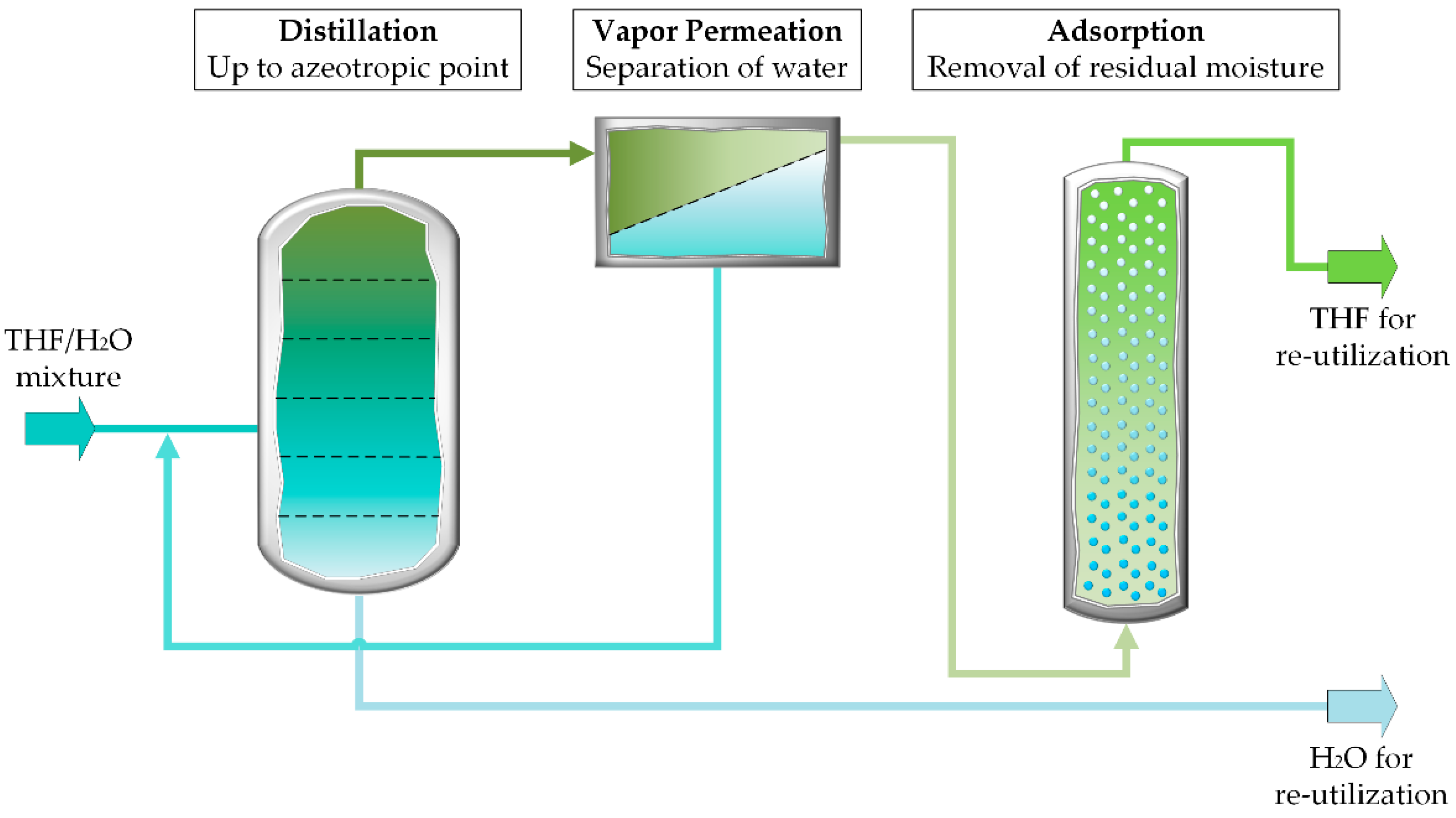
Figure 1 shows how the solvents used in a polymerization process can be reused in the next polymerization process. The organic solvent–water mixture produced after polymer synthesis and subsequent precipitation of polymer product is to be processed in the hybrid process so that the organic solvent can be used again in a new polymer synthesis experiment and the water can be used again for the precipitation of the polymer. In this hybrid process, distillation, membrane separation and adsorption are combined in such a way that purification of the solvent and nonsolvent is achieved with low energy input. The individual advantages of the different processes are combined by using distillation for coarse separation, the membrane process to overcome the azeotropic point and adsorption for ultrafine purification. Due to the complexity of the targeted hybrid process (safety aspects, expenses, and demands for large rooms to host this pilot plant), the simulation-based development of the process before the construction of a plant is of great importance. Additionally, the models for the simulation can be used for the advancement of the process and for the monitoring of the process as well as the examination of the possibilities of using this plant for additional separation tasks. Therefore, this work proposes a novel closed loop process, supported by the simulation that can be further applied for the utilization of the organic waste mixtures from the upstream polymer synthesis, which differs from other processes in particular due to the high purity of the processed products.
4. Hybrid Process Simulation
The software Aspen Plus Dynamics
® v.11 was used to represent the entire hybrid process in one simulation. For a precise representation of the distillation column, it was first configured in Aspen Plus
® and then imported into Aspen Plus Dynamics
® as flow driven file. For the calculation of the membrane and adsorption part of the process, the models created in Aspen Custom Modeler
® were imported into Aspen Plus Dynamics
®. Details of the Aspen Custom Modeler
® models are provided in the
Appendix A. Thus, all required models for representing the interconnected hybrid process were available in Aspen Plus Dynamics
®.
The simulation of the distillation column was first performed with the software Aspen Plus® v.11 based on a rigorous model, whereby the initial values for the design were determined using the McCabe–Thiele method employing the vapor–liquid equilibrium diagram of the binary mixture that is to be investigated. Since this varies with the pressure, the operating pressure of the column must be set as an assumption first. The selection of the operating pressure depends on the distillation process and the membrane process because with the intended design, further compression of the process stream between the distillation column and membrane module can be avoided.
The analysis of the vapor–liquid equilibrium plotted in terms of THF vapor phase mass fraction vs. THF liquid phase mass fraction reveals that an increase in pressure results in a shift of the azeotropic point. The higher the pressure is, the lower the THF mass fraction in the vapor phase (see
Figure 3). Hence, too high pressure is undesirable because of the shift to more significant amounts of water in the top product. Furthermore,
Figure 3 indicates that the vapor in equilibrium with the feed at a THF mass fraction of 20 wt.-% is in equilibrium with a vapor containing THF in excess of 85 wt.-%. This observation led to the design of the distillation section of the process as a stripping column only since no rectifying section was necessary to increase the THF content of the distillate further. For the subsequent membrane process, higher pressure is useful for an increase in the driving force. Additionally, the working range of the membrane module, including the thermal stability of the membrane material, and the energy costs had to be considered when fixing the operating pressure and hence minimum temperature for operation of the vapor permeation module. For this hybrid process, a pressure of 4 bar was selected to support good separation results in the vapor permeation stage, ensuring the stability of the membrane material and having a high enough THF content in the distillate.
Another important aspect in selecting the operating pressure is the existence of a miscibility gap in the THF–H
2O mixture. Similar to the azeotropic point of this mixture, the miscibility gap depends on the pressure [
29]. However, since the first step of the stripping process does not exceed the value of 86 mass percent THF in the vapor phase that lies before the miscibility gap, which starts at a value of 89 mass percent THF, and the separation mechanisms of the following process steps operate independently of the vapor–liquid equilibrium, choosing the hybrid process to purify this mixture, the miscibility gap does not pose a problem.
After setting the working pressure, the McCabe–Thiele method can be applied to the corresponding vapor–liquid equilibrium diagram to determine a first estimate for the number of stages of the stripping column. As initial values for the calculation of the stripping column, a number of five stages was selected.
In the following, Aspen Plus
® v.11 software was used for creating a rigorous equilibrium stage model based on the RadFrac model. The process was designed with regard to the composition of the bottom product. For this purpose, a water mass fraction in the bottom product of 99.9 wt.-% was assumed, whereas the THF composition of the distillate was assumed to be in equilibrium with the liquid exiting the feed stage, resulting in a vapor mass fraction of 88.57 wt.-% (
Figure 3). A material balance around the column results in a bottoms mass flow rate of 38.75 kg·h
−1 that was employed as specification for the RadFrac model. A total number of five stages including the reboiler was simulated, although a McCabe–Thiele design indicated that a number of four stages was sufficient. The additional stage was employed in order to provide flexibility in the intended operation of the process in a research environment.
The temperature inside the stripping column decreases from bottom to top and varies between 146 and 109 °C. The main points of the column’s configuration are summarized in
Table 1. With this design of the stripping column, it is possible to produce a recycled water stream with a purity of 99.8 mass percent from the feed stream with a water content of 80 mass percent. In addition to the recycled water, this process step results in a THF–H
2O mixture containing 11.7 mass percent water. The further purification of the mixture takes place in the following process steps.
In addition, the size of the distillation plant was checked to see if it meets the requirements of an application on a pilot plant scale. Therefore, the diameter of the required column was determined based on the simulation results with Aspen Plus
®. The following equation was used to calculate the column diameter
[
30]:
The pressure
and temperature
are given by the operating conditions and the flow rate
is derived from the results of the previous Aspen Plus
® simulation, which specifies the configuration of the distillation column. In order to determine the flood point velocity
, it is necessary to consider further mathematical coherences and parameters, which express the properties of the structured packing (porosity
, hydraulic diameter of the structured packing
, resistance coefficient of the dry packing
) and the droplet diameter
, see Equation (2) [
30,
31]. The calculation of the flood point velocity
is based on the drop–float–bed model [
32]:
where
is the difference between liquid and vapor density,
is the gravity, and
is the vapor density.
Choosing a structured packing Mellapak 752.Y from Sulzer Chemtec [
33,
34] results in a column diameter of about 7 cm. The height of the column is determined by the number of stages and the packing material, which specifies the number of stages per meter column height. For the selected column material and number of stages, determined in the Aspen Plus
® simulation, the column height is approximately 1.6 m. With these dimensions, this column is well suited for operation in the intended hybrid process on a pilot plant scale.
In order to ensure that the feed to the stripping column is in saturated liquid state, a heat exchanger was included into the Aspen Plus® simulation. The heat exchanger, in combination with the stripping column, was exported into a file format readable by Aspen Plus Dynamics® in order to combine this detailed process description with the following process steps.
In the second process stage, the top product of the distillation process is further purified by vapor permeation. This kind of membrane process is characterized by the fact that the feed, retentate, and permeate are in the vapor phase. This is an advantage compared to the related pervaporation process in combination with distillation, in which there would be a phase transformation within the membrane modules, i.e., the evaporation of the permeate, which leads to a cooling effect. This cooling would have to be counteracted by intermediate heating, in case of using a pervaporation process with several modules connected in series. Therefore, by choosing vapor permeation as process, additional energy for reheating can be saved. A common characteristic of the two processes is that the driving force, as for every membrane process, can be described by the difference of chemical potential. It can be shown that this can be replaced by the difference in fugacities for vapor permeation. For the introduced process, a pressure of 4 bar on the feed side and a vacuum of 0.05 bar absolute on the permeate side are employed to generate the driving force. Mass flow, composition, temperature, and pressure of the feed stream correspond to the top product of the previous distillation process.
For the simulation, a model developed by Brinkmann [
27] was implemented in the Aspen Plus Dynamics
® file, which already contains the distillation part. This model was validated with experimental results collected with a pilot plant for ethanol dehydration. Changing variables along the membrane area, such as concentration and mass flow, required the solution of the system of differential and algebraic equations containing, e.g., material balance and permeation relationship. For the simulation of the membrane module, pressure drops on feed and permeate side were neglected, and no impact of concentration polarization and isothermal operation were assumed. The permeation through the membrane is described by
where
is the permeate molar flux of component
,
is the universal gas constant,
is the standard temperature,
is the standard pressure,
is the permeate volumetric flow rate at standard temperature and pressure of component
,
is the membrane area,
is the permeance of component
, and
is the fugacity of component
for the high pressure (
) and low pressure (
) side of the membrane.
The permeance is determined by the free-volume model (FVM), which was developed by Fang et al. [
28] as a form of the solution–diffusion model for swelling polymers, defined as follows:
where
describes the permeance of a component
for the case of infinite dilution and
is the Lennard–Jones coefficient.
In order to assess the feasibility of this process, the parameters for the permeance
are based on investigations of the permeation of isopropanol–water mixtures with a polymer membrane having poly(vinyl alcohol) as the selective layer [
35]. For this study, the permeation behavior of THF is assumed to be represented by that of isopropanol. The parameters used in the free-volume model are summarized in
Table 2.
Condition for the design of the membrane module is a purification of the THF stream in the retentate stream to 99 mole percent. The result is a membrane area of 517 cm² under the design conditions summarized in
Table 3. This size is well suited for implementation in a pilot plant. A membrane module type that can be applied for the flat sheet membranes is an envelope type membrane module specifically designed for pilot plant application and introduced, e.g., in [
38]. For this membrane area, a feed stream with a THF concentration of 65.15 mole percent results in a THF concentration in the permeate of 6.5 mole percent. This value is similar to the composition of the feed stream into the stripping column so that it can be recycled to the column after condensation for further processing without significantly affecting the operating conditions of the column.
About 99 mass percent of the water stream fed to the pilot plant is already separated from the organic solvent in the first distillation step. Nevertheless, the results confirm that ultrafine purification is not possible with the membrane vapor permeation separation process alone since the decrease of water driving force toward the retentate side renders this impossible. The composition and mass flow of the retentate is used in the following as input flow for the adsorption column.
As last step of the hybrid process, a model for an adsorption column is added to the Aspen Plus Dynamics® simulation to examine the scale and the time frame for a high-quality purification of the THF product stream from the combination of distillation and vapor permeation process. To calculate the breakthrough curve, the dimension of the column must be specified. Based on the assumption that the stream resulting from the previous simulation of the combined process of stripping column with membrane module should be purified at a typical liquid adsorption superficial velocity value of 0.17 cm·s−1, the diameter of the adsorption column is 5 cm. For the dehydration of the stream in the adsorption column, molecular sieve 4Å (Mole Sieve 4A) was selected as the proper adsorption material in form of spheres. The quantity of water to be adsorbed, over a period of approximately 2 h, requires a calculated quantity of 400 g of this adsorption material. This results in a minimum height of the adsorber bed of 30 cm.
The adsorption behavior of a material is described by its adsorption isotherms. The adsorption isotherm for water on Mole Sieve 4A is following the Langmuir adsorption model. This type of isotherm is valid under the assumptions of energetic equality and accessibility of all adsorption sites, no interactions between the adsorbate molecules and a monomolecular coverage of the adsorbent surface. The Langmuir coefficients were taken from Pahl [
39] and are 8287 m³·mole
−1 for the Langmuir constant b and 9.11 mole·kg
−1 for the maximum adsorption q
mon. Equation (5) describes the loading of the adsorption material
.
The model for the adsorption column consists of differential material balances for both components. The velocity is assumed to be constant due to the low water content, while axial dispersion is accounted for by a fixed dispersion coefficient. Mathematically, the material balance is expressed by a partial differential equation, first order with respect to time and second order with respect to axial coordinate. For each spatial location, instantaneous equilibrium between liquid and adsorbate phase is assumed according to Equation (5) for water, whereas no adsorption of THF is considered. Since no extra- or intraparticle mass transfer is considered, liquid and solid phase are combined within one material balance for each component. As already pointed out, the adsorption process is assumed to be isothermal. The created model provides the calculation of the breakthrough curve to check the process conditions and the application in the pilot plant scale. The used adsorption bed specifications, which result from the requirement of the whole hybrid process operation during one working day and the selected adsorption material for efficient dehydration of organic solvent, are summarized in
Table 4. The result of the simulation is discussed in the next paragraphs. At a temperature of 25 °C and a pressure of 4 bar, the adsorption material is fully loaded after a time of about 2 h and cannot adsorb any further water molecules. To ensure sufficient dehydration by the adsorption process, the dimension of the column could, therefore, be adjusted. This can easily be realized by increasing the column height, which, even if doubled, still fits nicely into the desired dimensions of a pilot plant. The model predicts a THF stream with 100% purity up to the onset of breakthrough. Since bypass flows within the adsorption column can occur during actual operation, the purity of the product has to be verified experimentally for an accurate statement; however, due to the complexity of the construction of such a pilot-scale plant, this will be investigated in future work. The suitability of adsorption processes for the removal of water to produce high-purity organic solvents has already been proven in experimental studies [
40,
41].
After the adsorption column has been fully loaded, the adsorption material must be regenerated before the column can be put into operation again. The inert gas nitrogen is particularly suitable for this purpose. This is the only waste product generated during the hybrid process described because the solvent mixture itself can be separated and purified in sufficient quality for reutilization.
Figure 4 shows the whole process as simulated in Aspen Plus Dynamics
® with all steps in combination. The original feed stream is first fed into a vessel (V1) that allows mixing with the permeate stream of the membrane module. Due to the similar composition of the permeate, compared to the feed of the entire process, its addition to the inlet stream of the stripping column has no significant effect on the configuration of this column.
Figure 5 shows the simulation results for the molar composition of the liquid and vapor phase inside the stripping column for each stage. In
Figure 5a, the values for the vapor and liquid mole fraction for THF are shown, while in
Figure 5b, the results for H
2O are shown. Stage one has the same composition as the feed due to the fact that in this stage, the feed inlet is located. With increasing stage number, the THF mole fraction decreases in the stripping column. The difference between stages four and five is hardly visible in the plotted graph. The simulation with Aspen Plus
®, therefore, supports the previous estimation according to the McCabe–Thiele method, i.e., a large part of the purification can already be achieved with four stages. The composition in stage five shows the purity in the bottom product. The bottom product consists of 99.99 mass percent H
2O. Thus, one of the main requirements for the products of this hybrid process is fulfilled since this product stream can be reused, for example, for the precipitation of new polymers. The top product continues to be a mixture of THF and H
2O with above 14 mass percent H
2O. It is only in the next process step that a purification larger than 99 mass percent THF is achieved by using the membrane process. This further purification of the top product by linking it to a membrane module is shown in
Figure 6a, which describes the change in composition of the retentate stream. The green line shows the increasing THF mole fraction in the retentate over the membrane area. After reaching 80% of the membrane area, the retentate stream already has a purity of 0.98 mole·mole
−1. The purification of the organic solvent in high quality takes place in the last process step, the adsorption process.
Figure 6b shows the breakthrough curve of the adsorption column generated by the simulated hybrid process. The breakthrough of the adsorption column starts after approximately 115 min and ends after approximately 125 min. These times correspond to the required feasibility of the process, which, in a realistic scenario, should be able to recycle a quantity of 100 l of mixture of organic solvent and water within one working day. As a result, in addition to the recycling of H
2O, THF can also be recovered in sufficient quality for repeated use as a solvent in polymerization processes. In this way, a zero-discharge process is created that reprocesses both components of the original mixture.
Investigation of Energy Consumption
In view of the fact that a sustainable, resource-saving process is to be developed, its energy consumption is a key parameter. Therefore, the energy consumption of the process was investigated. Since this depends to a large extent on the operating pressure, the influence of this factor was analyzed by variation. For this purpose, seven different feed pressures between 2 and 8 bar were investigated.
Figure 7a shows the energy consumption for the whole process depending on different feed pressures, which includes the individual energy consumptions of pumps, heat exchangers, and the reboiler for the operation of the stripping column. The main part of the energy consumption consists of the heating power of the hybrid process with approximately 80%. Just under 20% results from the necessary cooling power, while the remaining energy is used for electrical power. Besides the total energy consumption,
Figure 7a shows the data for the energy consumption of the stripping column as a single data set. This includes the reboiler of the column itself and the heater for the feed stream. It can be observed that the first process step with stripping accounts for the largest share of the energy consumption of the entire process. The membrane process, on the other hand, consumes only 9 percent of the total energy consumption due to the additionally required vacuum pump and heat exchanger. The distillation process step shows a strong dependence on the pressure in the range investigated. To account for the effect of pressure change on the efficiency of the processes,
Figure 7b shows the molar fraction of THF in the top product of the stripping column and that in retentate and permeate of the membrane process. The top product of the stripping column shows a decreasing THF content with increasing pressure. The permeate stream from the membrane process shows a sharp increase in THF content from a pressure of 4 bar, while the retentate stream shows only a small increase in THF content. This is expected since a molar content of 0.99 is already present at 4 bars. The increase of the THF content in the permeate stream above a value of 6 mole percent is not desired since this stream is to be added to the feed of the stripping column and would increase the load on the column. It is not surprising that the figures shown indicate favorable operation at 4 bars since the configuration of the column and the membrane area are designed for this operating condition. Nevertheless, a consideration in comparison with the dependence of the energy consumption on the pressure is useful, since ultimately, it must be decided whether the energy consumption of the recycling process represents a significant improvement over the production of new solvent, taking into account the achieved purification target. In order to save an additional compressor upstream of the membrane process and take into account the increasing strain on membrane material with increasing pressure, the choice of a feed pressure of 4 bar represents an acceptable compromise. The configuration of the process at a feed pressure of 4 bar results in an energy consumption of 191.8 W per kg·h
−1 of feed mixture to be purified. Calculating the energy required to produce one kg of pure THF from the waste stream that would otherwise be discarded, the value is 3.5 kJ·kg
−1. In addition to reducing the raw material requirement, the use of the process described here for recycling and reuse of the THF and water in the preceding process of polymer synthesis can also save the energy that would otherwise be required for the proper disposal of organic solvent.


