Article

Impact-Rubbing Dynamic Behavior of Magnetic-Liquid Double Suspension Bearing under Different Protective Bearing Forms

1
Fluid Power Transmission and Control Laboratory, Yanshan University, Qinhuangdao 066004, China
2
College of Civil Engineering and Mechanics, Yanshan University, Qinhuangdao 066004, China
*
Author to whom correspondence should be addressed.
Processes 2021, 9(7), 1105; https://doi.org/10.3390/pr9071105
Submission received: 23 March 2021 / Revised: 17 June 2021 / Accepted: 22 June 2021 / Published: 25 June 2021

Abstract

:
The magnetic-liquid double suspension bearing (MLDSB) is a new type of suspension bearing, with electromagnetic suspension as the main part and hydrostatic supports as the auxiliary part. It can greatly improve the bearing capacity and stiffness of rotor-bearing systems and is suitable for a medium speed, heavy load, and frequent starting occasions. Compared with the active electromagnetic bearing system, the traditional protective bearing device is replaced by the hydrostatic system in MLDSB, and the impact-rubbing phenomenon can be restrained and buffered. Thus, the probability and degree of friction and wear between the rotor and the magnetic pole are reduced drastically when the electromagnetic system fails. In order to explore the difference in the dynamic behavior law of the impact-rubbing phenomenon between the traditional protection device and hydrostatic system, the dynamic equations of the rotor impact-rubbing in three kinds of protection devices (fixed ring/deep groove ball bearing/hydrostatic system) under electromagnetic failure mode are established, and the axial trajectory and motion law of the rotor are numerically simulated. Finally, the dynamic behavior characteristics of the rotor are compared and analyzed. The results show that: Among the three kinds of protection devices (fixed ring/deep groove ball bearing/hydrostatic system), the hydrostatic system has the least influence on bouncing time, impact-rubbing force, and impact-rubbing degree, and the maximum impact-rubbing force of MLDSB is greatly reduced. Therefore, the protective bear is not required to be installed in the MLDSB. This study provides the basis for the theory of the “gap impact-rubbing” of MLDSB under electromagnetic failure, and helps to identify electromagnetic faults.

1. Introduction

The magnetic-liquid double suspension bearing (MLDSB) is a new type of suspension bearing, with electromagnetic suspension as the main part and hydrostatic supports as the auxiliary part. With this, the bearing capacity, operation stability, and service life of rotor-bearing systems can be greatly improved. MLDSB is suitable for hydroelectric power, deep-sea exploration, and other fields, especially those that feature a medium speed, heavy load, and frequent starting occasions.
The MLDSB Test Table includes a variable speed motor, coupling, radial bearing, axial bearing, axial loading motor, radial loading motor, step shaft, and frame, as shown in Figure 1 [1].
The radial bearing includes a rotor, magnetic sleeve, supporting cavity, magnetic pole, oil inlet/return hole, shell, and coil, as shown in Figure 2 and Figure 3 [1]. The magnetic pole and magnetic guide sleeve were treated with chromium plating to prevent them from being corroded due to their immersion in oil for a long time [2,3].
The regulation principle of MLDSB is shown in Figure 4 [1]. The PD control and constant pressure supply mode are adopted in the electromagnetic system and hydrostatic system, respectively, to realize real-time regulation of the rotor [1].
Electromagnetic system failure, which is caused by electromagnetic coil corrosion and power amplifier circuit fault [4,5], will lead to friction and excessive wear between the rotor and magnetic pole, causing the structural strength and reliability of the electromagnetic bearing to be severely reduced. Thus, the fixed ring/deep groove ball bearings and other protective devices are equipped with AMB (Active Magnetic Bearings) to improve the operation stability.
In recent years, many scholars at home and abroad have deeply studied the impact-rubbing dynamics of AMB and achieved many results.
Professor JARROUX [6] studied the rotor drop dynamics numerically and experimentally when AMB unexpectedly stops. The finite unit method and three kinds of TDB models were used to simulate rotor drops in the time domain and measure rotor drop responses, according to the displacement and transmission load.
Professor PATPICK [7] studied the control scheme of AMB when intermittent fault or overload occurs. The results showed that proper forced phase synchronization can destabilize the synchronous forward friction response. The rotor under contact rubbing and slight rotational motion is beneficial to the system and does not interfere with the main electromagnetic bearing control loop.
A robust control strategy to ensure suspension recovery was proposed by Professor PESCH [8]. The specific AMB control laws were found by using model-based optimization synthesis to explain and prevent electromagnetic levitation failure, caused by large deformations, using control contact force saturation.
The dynamic model was established by Professor Zhao [9] to study the dynamic characteristics of rotor drops, and a PID control system for a magnetic bearing was designed with contact possibilities. The control strategy was theoretically demonstrated to be effective in returning a rotor to the contact-free levitation position and avoid further fierce contacts under several circumstances involving external disturbances.
The falling behavior of the spindle structure of a vertical axis magnetic levitation wind turbine was simulated by Professor Wu [10] The movement track of the spindle in the axial direction was compared to visually illustrate the influence of different protective bearing structures on the movement track of the magnetic suspension spindle in the falling process.
The situation of the AMB falling on the self-eliminating clearance protection bearing after failure was studied by Professor Xu [11,12,13,14]. Compared with the traditional roller bearing, the self-eliminating clearance protection bearing significantly reduced the vibration of the rotor after falling, and the falling of the high frequency speed was more reliable.
Professor Zdzislaw [15] studied H∞ and H2 control of rigid rotor movement, which is supported in magnetic bearings, and investigated the robust control of magnetic bearings. The paper proposes robust control with a multi-objective controller to achieve good robust stability when the model of a plant is uncertain. Finally, the success of the robust control is verified by numerical simulation results.
Compared with the traditional AMB, the hydrostatic system is used in MLDSB here to replace the protection devices, so that it not only effectively supports the rotor, but can also buffer the friction fault of the rotor. In this way, the wear degree and probability between the rotor and the magnetic pole can be reduced. However, the protection mechanism of the rotor/stator by the static pressure system in this new bearing system is not clear yet, and the difference between the static pressure system and the traditional protection bearing needs to be explored. Therefore, the dynamic equations of the rotor impact-rubbing in three kinds of protection devices (fixed ring/deep groove ball bearing/hydrostatic system) under electromagnetic failure mode are established in this paper, and the axial trajectory, motion law, and dynamic behavior characteristics of the rotor are numerically simulated and analyzed.

2. Rotor Impact-Rubbing Model during Electromagnetic Failure

The time of rotor impact-rubbing is very short, so the assumptions are as follows [16,17]:
(1)
There is a local elastic collision between the magnetic pole and the magnetic jacket, and the deformation is elastic deformation;
(2)
The winding magnetic flux leakage, edge magnetic flux, eddy current loss, core material saturation, and coupling effect between magnetic poles are ignored;
(3)
The tiny gaps between the poles are ignored;
(4)
The inertial force and viscous pressure characteristics of the liquid are ignored;
(5)
The gravity of the inner ring of deep groove ball bearings is ignored;
(6)
The deep groove ball bearing is simplified into a spring damping system with mass.

2.1. Impact-Rubbing Dynamics Model of the “Rotor-Fixed Ring”

The mechanical model of rotor impact-rubbing on the fixed ring protection device in electromagnetic failure mode is shown in Figure 5, and the mathematical equations of the supporting system are shown as follows [18].
{ F M x , j + F x = m x ¨ F M y , j + F y m g = m y ¨ J θ ¨ = F t r
{ F M x , j = μ 0 S N 2 cos φ 2 j = 1 2 ( 1 ) j + 1 [ i 0 + ( 1 ) j ( k p x y + k d x x ˙ ) h 0 + 2 l + ( 1 ) j x cos φ ] 2 F M y , j = μ 0 S N 2 cos φ 2 j = 1 2 ( 1 ) j + 1 { i 0 + ( 1 ) j [ m g ( h 0 + 2 l ) 2 2 μ 0 i 0 S N 2 cos φ + k p y y + k d y y ˙ ] h 0 + 2 l + ( 1 ) j y cos φ } 2
{ F n = { k 1 ( x 2 + y 2 h 1 ) e 1 + c 1 x ˙ x + y ˙ y x 2 + y 2 x 2 + y 2 h 1 0 0 x 2 + y 2 h 1 < 0 F t = f 1 F n F x = F n x 2 + y 2 ( x f 1 y ) F y = F n x 2 + y 2 ( f 1 x + y )
where FMx and FMy are the electromagnetic supporting forces in the x and y directions [19]. Fx and Fy are the components of the impact-rubbing force in the x and y directions. m is the rotor mass. g is the gravity acceleration. J is the inertia moment around the centroid of the rotor. θ is the angular displacement. Fn and Ft are the radial and tangential impact-rubbing forces [20]. R is the radius of the rotor. φ is the angle between the magnetic pole and the center line of the rotating shaft. h0 and h1 are the initial unilateral clearance between the rotor and magnetic pole and the inner ring of the protection device, respectively. μ0 is the vacuum permeability. l is the coating thickness. i0 is the bias current. S is the area of the magnetic poles. N is the number of coil turns. kpx and kdx are the scale and differential coefficients in the x direction. kpy and kdy are the proportional and differential coefficients in the y direction. e1, k1, c1, and f1 are the contact coefficient, stiffness, damping, and friction coefficient of the rotor in contact with the inner ring of the protection device, respectively.
Electromagnetic system failure in the paper includes the failure of solely the upper unit and the failure of the upper and lower units. The mathematical model of the impact-rubbing dynamics is shown in Equation (1), which just requires the following changes:
{ F M y , 1 = 0 Upper   unit   failure F M y , 1 = F M y , 2 = 0 Upper / Lower   units   failure

2.2. Impact-Rubbing Dynamics Model of the “Rotor-Deep Groove Ball Bearing”

The mechanical model of the rotor impact-rubbing on the deep groove ball bearing under electromagnetic failure mode is shown in Figure 6, and the mathematical model of the supporting system is shown as follows [18].
{ F M x , j + F x 1 = m x ¨ F M y , j + F y 1 m g = m y ¨ J θ ¨ = F t 1 r F x 2 F x 1 = m b x ¨ b F y 2 F y 1 = m b y ¨ b J b θ ¨ b = ( F t 2 F t 1 ) ( h 1 + r )
{ F n 1 = { k 1 [ ( x x b ) 2 + ( y y b ) 2 h 1 ] e 1 + c 1 ( x ˙ x ˙ b ) ( x x b ) + ( y ˙ y ˙ b ) ( y y b ) ( x x b ) 2 + ( y y b ) 2 ( x x b ) 2 + ( y y b ) 2 h 1 0 0 ( x x b ) 2 + ( y y b ) 2 h 1 < 0 F t 1 = f 1 F n 1 F x 1 = F n 1 ( x x b ) 2 + ( y y b ) 2 [ ( x x b ) f 1 ( y y b ) ] F y 1 = F n 1 ( x x b ) 2 + ( y y b ) 2 [ f 1 ( x x b ) + ( y y b ) ]
{ F n 2 = k 2 ( x b 2 + y b 2 ) e 2 + c 2 x ˙ b x b + y ˙ b y b x b 2 + y b 2 F t 2 = f 2 F n 2 F x 2 = F n 2 x b 2 + y b 2 ( x b f 2 y b ) F y 2 = F n 2 x b 2 + y b 2 ( f 2 x b + y b )
where Fx1 and Fy1 are the components of the impact-rubbing force acting on the rotor in the x and y directions. mb is the mass of the bearing’s inner ring. Fx2 and Fy2 are the components of the impact-rubbing force acting on the inner ring of the bearing in the x and y directions. xb and yb are the displacements of the bearing’s inner ring in the x and y directions. Jb is the moment of inertia of the bearing’s inner ring around the centroid. θb is the angular displacement of the bearing’s inner ring. Fn1 and Ft1 are the radial and tangential impact-rubbing forces acting on the rotor. Fn2 and Ft2 are the radial and tangential impact-rubbing forces acting on the inner ring of the bearing. e2, k2, c2, and f2 are the contact coefficient, stiffness, damping, and friction coefficient of the bearing’s inner ring in contact with the ball, respectively.
The mathematical model of the impact-rubbing dynamics in the deep groove ball bearing is shown in Equation (3), which requires the changes as shown in Equation (2).

2.3. Impact-Rubbing Dynamics Model of the “Rotor-Hydrostatic System”

The mechanical model of the impact-rubbing dynamics on the hydrostatic system under electromagnetic failure mode is shown in Figure 7, and the mathematical model of the supporting system is shown as follows.
{ F L x , j + F M x , j + F x = m x ¨ F L y , j + F M y , j + F y m g = m y ¨ J θ ¨ = F t r
{ F L x , j = j = 1 2 { ( 1 ) j 2 p s A e cos φ 1 + ( β 1 ) [ 1 + ( 1 ) j x h 0 cos φ ] 3 2 A b A e R h j , x x ˙ cos φ } F L y , j = j = 1 2 { ( 1 ) j 2 p s A e cos φ 1 + ( β 1 ) [ 1 + ( 1 ) j y h 0 cos φ ] 3 2 A b A e R h j , y y ˙ cos φ }
{ R h j , x = μ B ¯ [ h 0 + ( 1 ) j x cos φ ] 3 R h j , y = μ B ¯ [ h 0 + ( 1 ) j y cos φ ] 3 j = 1 , 2
where FLx and FLy are the hydrostatic force in the x and y directions [21]. ps is the oil supply pressure. Ae and Ab are the effective bearing area and extrusion area of the supporting cavity, respectively. Rhj is the fluid resistance of the bearing cavity after loading. μ is the oil viscosity. B ¯ is the flow coefficient [22]. β is the throttling ratio.
The mathematical model of the impact-rubbing dynamics in the hydrostatic system is shown in Equation (4), which requires the changes as shown in Equation (2).

3. Numerical Simulation of the Rotor Impact-Rubbing Process under Electromagnetic Failure

The initial design parameters of the fixed ring/deep groove ball bearing/hydrostatic system support are shown in Table 1.

3.1. Impact-Rubbing Dynamics Behavior of the Rotor-Fixed Ring Supporting System

  • Impact-rubbing behavior of the rotor under upper unit failure mode
The axis trajectory of the rotor falling on the fixed ring under upper unit failure mode is shown in Figure 8.
According to Figure 8, the impact-rubbing phenomenon of the rotor can be divided into the bouncing stage and eddy stage, when the upper unit fails. When the rotor falls directly on the fixed ring, it firstly bounces and collides and then vortexes repeatedly forward/backward.
In order to further analyze the bounce-eddy situation of the rotor falling, the rotor displacement, phase trajectory, rubbing force, and electromagnetic force were extracted, as shown in Figure 9.
According to Figure 9, the bouncing stage mainly occurs within 0.07 s. The rotor displacement, impact-rubbing force, and residual electromagnetic force shake violently, and their amplitudes gradually decrease. The maximum impact-rubbing force is 880 N.
The eddy stage mainly occurs after 0.07 s. The displacement gradually converges at about −26 μm, which is larger than the unilateral air gap, indicating that the rotor will eventually stagnate at the bottom of the fixed ring. The phase trajectory presents a double-periodic closed circle from the outside to the inside, which indicates the displacement tends to converge. The variation of the impact-rubbing force/electromagnetic force is similar to that of the displacement, respectively, converging at about 125 N and −25 N, and their vector sums are just in balance with the rotor’s gravity.
2.
Impact-rubbing behavior under upper and lower unit failure
The axis trajectory of the rotor under upper and lower unit failure mode is shown in Figure 10.
Similarly, the impact-rubbing phenomenon of the rotor can be divided into the bouncing stage and eddy stage, when the upper unit fails. When the rotor falls directly on the fixed ring, it bounces and collides firstly and then vortexes repeatedly forward/backward.
Similarly, the rotor displacement, phase trajectory, rubbing force, and electromagnetic force were extracted, as shown in Figure 11.
According to Figure 11, the bouncing stage mainly occurs within 0.1 s. The rotor displacement, impact-rubbing force, and residual electromagnetic force shake violently, and their amplitudes gradually decrease. The maximum impact-rubbing force is 802 N.
The eddy stage mainly occurs after 0.1 s. In this stage, the displacement gradually converges at about −26 μm, which indicates the rotor will eventually stagnate at the bottom of the fixed ring. The phase trajectory presents a double-periodic closed circle from the outside to the inside, which indicates that the displacement tends to converge. There is no residual electromagnetic force, and the variation of the impact-rubbing force is similar to that of the displacement, converging at about 100 N, and the vector value is just in balance with the rotor’s gravity.

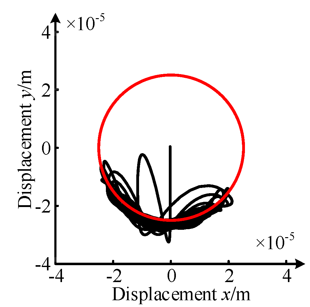
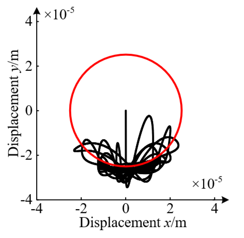
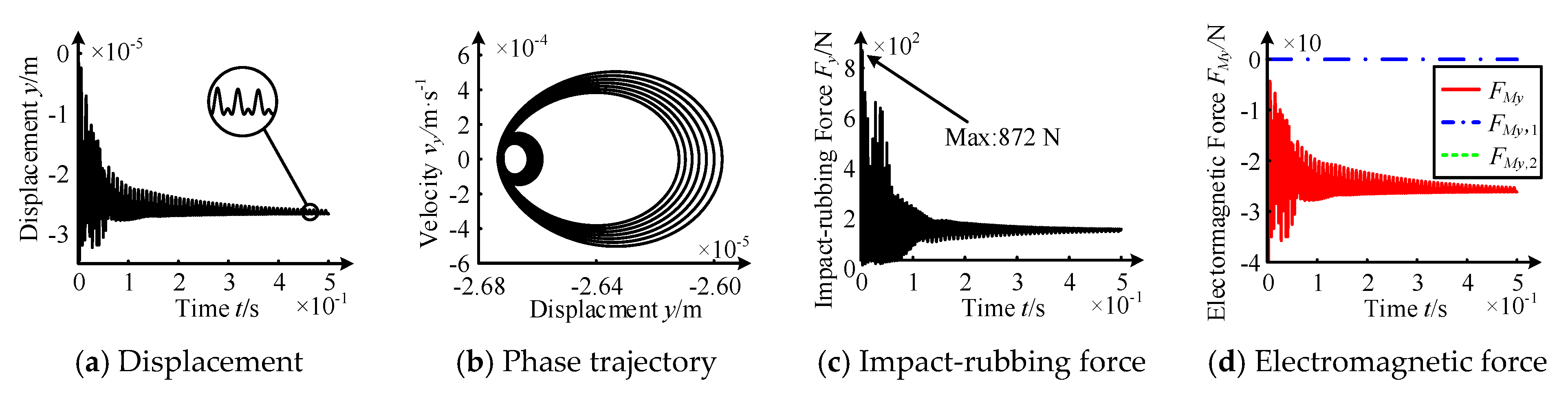
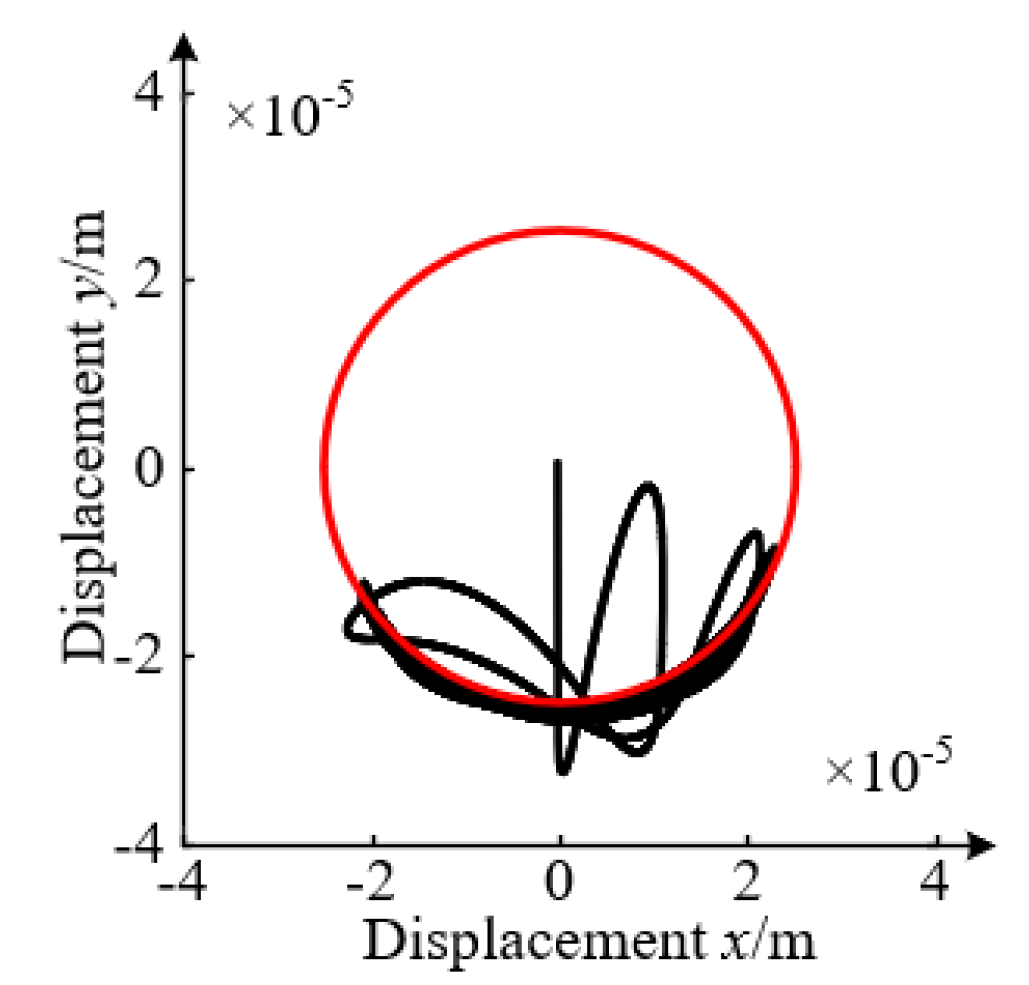
3.2. Impact-Rubbing Dynamics Behavior of the Rotor-Ball Bearings Supporting System

  • Impact-rubbing behavior law under upper unit failure
In the upper unit failure mode, the axis trajectory of the rotor falling in the deep groove ball bearing is shown in Figure 12.
Similarly, the impact-rubbing phenomenon of the rotor can be divided into the bouncing stage and eddy stage, when the upper unit fails. When the rotor falls directly on the inner ring of the ball bearing, it bounces and collides firstly and then vortexes repeatedly forward/backward.
Similarly, the rotor displacement, phase trajectory, rubbing force, and electromagnetic force were extracted, as shown in Figure 13.
According to Figure 13, the bouncing stage mainly occurs within 0.06 s. The rotor displacement, impact-rubbing force, and residual electromagnetic force shake violently, and their amplitudes gradually decrease. The maximum impact-rubbing force is 872 N.
The eddy phase mainly occurs after 0.06 s, and the displacement gradually converges at about −26 μm, which is larger than the unilateral air gap, indicating that the rotor will eventually stagnate at the bottom of the inner ring. The phase trajectory presents a double-periodic closed circle from the outside to the inside, which indicates the displacement tends to converge. The variation of the impact-rubbing force/electromagnetic force is similar to that of the displacement, respectively converging at about 126 N and −26 N, and their vector sums are just in balance with the rotor’s gravity.
2.
Impact-rubbing behavior law under upper and lower unit failure
In upper and lower unit failure mode, the axis trajectory of the rotor falling is shown in Figure 14.
Similarly, the impact-rubbing phenomenon of the rotor can be divided into the bouncing stage and eddy stage, when the upper unit fails. When the rotor falls directly on the inner ring of the ball bearing, it bounces and collides firstly and then vortexes repeatedly forward/backward.
Similarly, the rotor displacement, phase trajectory, rubbing force, and electromagnetic force were extracted, as shown in Figure 15.
According to Figure 15, the bouncing stage mainly occurs within 0.02 s. Both the rotor displacement and impact-rubbing force shake violently. The amplitude decreases gradually, and the maximum impact-rubbing force value is 788 N.
The vortex stage mainly occurs after 0.02 s. The displacement gradually converges at about −26 μm in this stage, indicating that the rotor will eventually stagnate at the bottom of the inner ring. The phase trajectory presents a double-periodic closed circle from the outside to the inside, which indicates that the displacement tends to converge. There is no residual electromagnetic force. The variation of the impact-rubbing force is similar to that of the displacement, respectively converging at about 100 N, and the vector value is just in balance with the weight of the rotor.

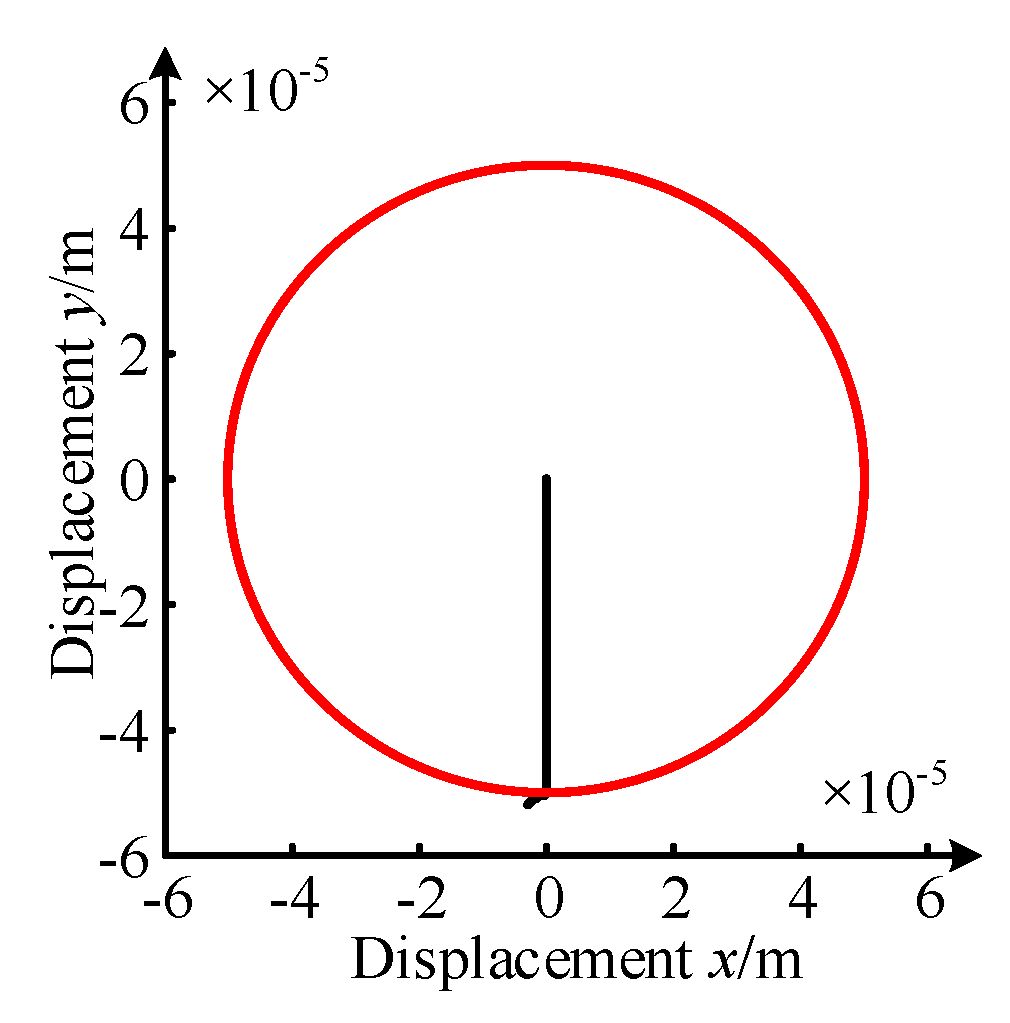
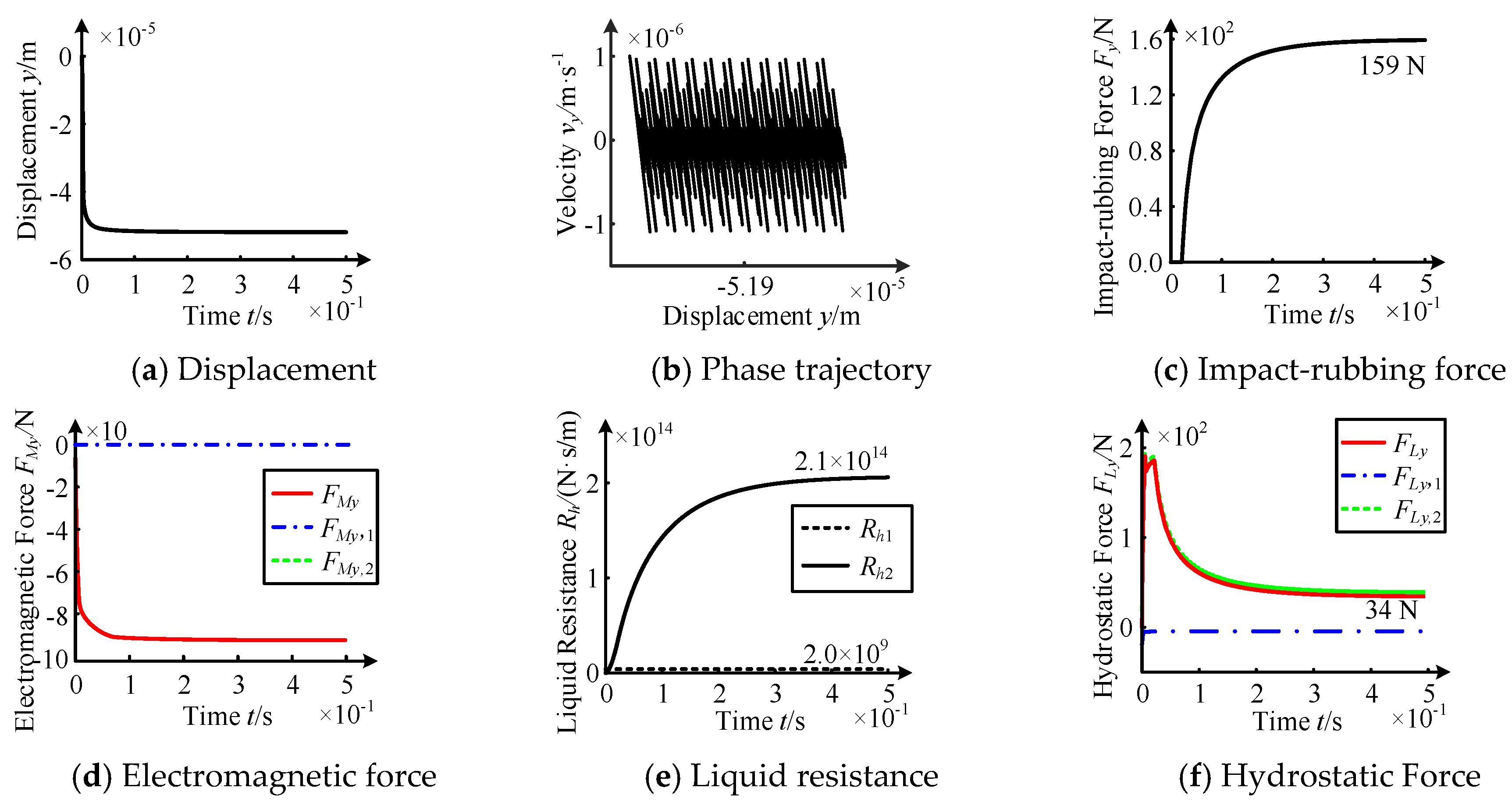
3.3. Impact-Rubbing Dynamics Behavior of the Rotor-Hydrostatic System

  • Impact-rubbing behavior law under upper unit failure
In upper unit failure mode, the axis trajectory of the rotor falling in the hydrostatic system is shown in Figure 16.
According to Figure 16, when the upper unit fails, the rotor directly falls to the magnetic pole with the contact and friction of a small tremor.
In order to analyze the impact-rubbing situation in the rotor-hydrostatic system, the rotor displacement, phase trajectory, rubbing force, electromagnetic force, hydraulic resistance, and hydrostatic force were extracted, as shown in Figure 17.
According to Figure 17, the drop stage mainly occurs within 0.02 s. The rotor displacement decreases rapidly, which means the rotor has a high speed, resulting in a rapid rise in the hydrostatic supporting force FLy. The fluid resistance Rh1 of the upper supporting unit almost does not change, but the fluid resistance Rh2 of the lower supporting unit increases due to the dynamic extrusion effect. The residual electromagnetic force FMy decreases rapidly.
The impact-rubbing contact stage mainly occurs after 0.02 s, and the rotor reaches a new equilibrium state: the phase trajectory shows the rotor displacement can achieve about −51.9 μm and the rotor vibrates periodically at this position at a low speed. As the contact depth between the rotor and stator increases gradually, the impact-rubbing force Fn increases to about 159 N, which can balance the rotor weight with the residual electromagnetic force FMy of −93 N and the hydrostatic force FLy of 34 N. The liquid resistance of the upper supporting unit and the lower supporting unit Rh1 and Rh2 respectively stabilize at 2.0 × 10⁹ N·s/m and 2.1 × 10¹⁴ N·s/m.
2.
Impact-rubbing behavior law under upper and lower unit failure.
In upper and lower unit failure mode, the axis trajectory of the rotor falling in the hydrostatic system is shown in Figure 18.
According to Figure 18, when both the upper and lower units fail, the rotor directly falls to the magnetic pole and collides with a little tremor.
Similarly, the rotor displacement, phase trajectory, impact-rubbing force, electromagnetic force, hydraulic resistance, and hydrostatic force are extracted, as shown in Figure 19.
According to Figure 19, the drop stage mainly occurs within 0.04 s. In this stage, the rotor displacement decreases rapidly, which indicates the rotor has a high speed, resulting in a rapid rise in the hydrostatic supporting force FLy. The fluid resistance Rh2 of the upper supporting unit shows little change, but the fluid resistance Rh2 of the lower supporting unit increases rapidly due to the dynamic extrusion effect. The resultant electromagnetic force FMy is 0.
The collision stage mainly occurs after 0.04 s, and the rotor reaches a new equilibrium state. The phase trajectory shows the rotor displacement can achieve about −51.9 μm and the rotor vibrates periodically at this position at a low speed. With the increase of the contact depth between the rotor and the stator, the impact-rubbing force Fn increases to about 66 N, which can balance the rotor weight with the hydrostatic force FLy of 34 N. The liquid resistance of the upper supporting unit and the lower supporting unit Rh1 and Rh2 respectively stabilize at 2.0 × 10⁹ N·s/m and 6.7 × 10¹³ N·s/m.

3.4. Comparison of the Three Protection Devices in Impact-RUBBING Behavior

  • Analysis of the impact-rubbing behavior under upper unit failure.
According to Figure 8, Figure 12 and Figure 16, it can be seen that under upper unit failure mode, the axis trajectories of the rotor falling in the fixed ring/deep groove ball bearings are basically the same. They both remain in the bouncing stage for a long time, followed by the forward/backward eddy stage, with a low value. Due to the dynamic extrusion effect of oil, only small tremors occur near the falling position of the rotor when it falls in the hydrostatic system, and there is no complex bouncing and eddy phenomena.
According to Figure 9, Figure 13 and Figure 17, it can be seen that the rotor displacement falling in the hydrostatic system is relatively stable in comparison with the fixed ring and deep groove ball bearing protection devices. The phase trajectory is no longer a double-periodic closed circle from the outside to the inside, but a periodic superposition with the same frequency. Compared with the fixed ring and deep groove ball bearings, the maximum impact force respectively decreases by 81.9% and 81.8% in the hydrostatic system. The variation of the residual electromagnetic force is gentler.
2.
Analysis of the impact-rubbing behavior under upper and lower units.
According to Figure 10, Figure 14 and Figure 18, it can be seen that under upper and lower unit failure mode, the axis trajectory of the rotor falling in the fixed ring firstly remains for a long time in the bouncing stage and then presents a low value for the forward/backward vortex phenomenon. A short bouncing phenomenon occurs in the case of falling in the deep groove ball bearing, and then presents a longer lasting time for the forward/backward vortex phenomenon. Due to the dynamic extrusion effect, only the small tremor occurs near the drop position in the case of falling in the hydrostatic system, and there is no complex bouncing and eddy phenomena.
According to Figure 11, Figure 15 and Figure 19, compared with the fixed ring and deep groove ball bearing protection devices, the displacement of the rotor falling in the hydrostatic system changes more stably, and only a slight tremor occurs under upper and lower unit failure mode. The phase trajectories show the form of reciprocating motion with the same frequency. The maximum impact force is reduced by 91.8% and 91.6%, and the degree of impact of the bounce and eddy is greatly reduced.
3.
Analysis of results.
In summary, the influence of the three protection devices on rotor impact-rubbing under electromagnetic failure mode is shown in Table 2 and Table 3.

4. Conclusions

  • The influences of the protection devices on the bouncing time, impact-rubbing force, and impact-rubbing degree are found to be as follows: the hydrostatic system shows the best results, followed by the deep groove ball bearing and then the fixed ring.
  • Compared with the fixed ring and deep groove ball bearing, the positions of the rotor impact-rubbing in the hydrostatic system are the rotor and magnetic pole, and the maximum impact-rubbing force is lower without bounce and eddy phenomena.
  • Compared with the bounce time and the maximum impact-rubbing force of the rotor in the three protective devices, it can be seen that there is no bounce phenomenon of the rotor in the hydrostatic system and the maximum impact-rubbing force is greatly reduced, so the protective bear is not required to be installed in the MLDSB.

Author Contributions

Conceptualization, J.Z.; Data curation, J.Z.; Methodology, J.Z.; Project administration, J.Z.; Resources, J.Z. and W.Y.; Software, L.X.; Supervision, D.G. and G.D.; Writing—original draft, L.X.; Writing—review and editing, L.X. and S.L. All authors have read and agreed to the published version of the manuscript.

Funding

This work was supported by the National Nature Science Foundation of China (no. 52075468); General project of Natural Science Foundation of Hebei Province (E2020203052); Youth Fund Project of scientific research project of Hebei University (QN202013); Open Project Funding of Jiangsu Provincial Key Laboratory of Advanced Manufacture and Process for Marine Mechanical Equipment and Open Project Funding of Fluid Power Transmission Control Laboratory of Yanshan University.

Data Availability Statement

Not applicable.

Conflicts of Interest

The authors declare no conflict of interest.

References

  1. Zhao, J.H.; Yan, W.D.; Wang, Z.Q.; Gao, D.; Du, G. Study on Clearance-Rubbing Dynamic Behavior of 2-DOF Supporting System of Magnetic-Liquid Double Suspension Bearing. Processes 2020, 8, 973. [Google Scholar] [CrossRef]
  2. Xiong, W.L.; Hu, C.; Lang, L.; Zheng L, G. Study on the Influence of Controllable Throttle Parameters on the Characteristics of Hydrostatic Bearing. J. Mech. Eng. 2017, 22, 3354–3359. [Google Scholar]
  3. Zhao, J.H.; Zhang, G.J.; Cao, J.B.; Gao, D.R.; Du, G.J. Decouping Control of Single DOF Supporting System of Magnetic-Liquid Double Suspension Bearing. Mach. Tool Hydraul. 2020, 48, 1–8. [Google Scholar]
  4. Zu, L.; Wang, H. Design and Research of Rotor Drop Protection System Test Bench. At. Energy Sci. Technol. 2015, 49, 340–386. [Google Scholar]
  5. Wang, X.H.; Yang, F.F.; Zhao, Q. Dynamics Analysis of Aircraft Engine Rotor Drop after Electromagnetic Bearing Failure. Gas Turbine Test. Res. 2019, 32, 1–7. [Google Scholar]
  6. Jarroux, C.; Dufour, R.; Mahfoud, J.; Defoy, B.; Alban, T.; Delgado, A. Touchdown Bearing Models for Rotor-AMB Systems. J. Sound Vib. 2018, 440, 51–69. [Google Scholar] [CrossRef] [Green Version]
  7. Patrick, K.; Matthew, C. Dynamic Conditions to Destabilize Persistent Rotor/Touchdown Bearing Contact in AMB Systems. Mech. Eng. J. 2017, 4, 17-00005. [Google Scholar]
  8. Pesch, A.H.; Sawicki, J.T.; Maslen, E.H. Active Magnetic Bearing Online Levitation Recovery through μ-Synthesis Robust Control. Actuators 2017, 6, 2. [Google Scholar] [CrossRef] [Green Version]
  9. Zhao, J.L.; Gong, H.L.; Yang, G.J.; Shi, C.G. Research on Drop Recovery Control Strategy of Electromagnetic Bearing Horizontal Rotor. Fan Technol. 2020, 62, 38–45. [Google Scholar]
  10. Wu, G.Q.; Lu, B.; He, D.W.; Song, C.G. Influence of Protective Bearing Structure on the Spindle Dropping Trajectory of Vertical Axis Maglev Wind Turbine. Mech. Des. Res. 2018, 34, 108–110. [Google Scholar]
  11. Wei, P.; Wang, Y.F.; Yang, Y.; Yan, J.L. Research on the Impact Force of High Speed Suspending Rotor Dropping on the Protective Bearing. Vib. Shock. 2018, 37, 251–258. [Google Scholar]
  12. Yu, C.T.; Xu, L.X.; Jin, C.W. Kinematics Analysis of Protective Clearance Mechanism for Automatic Elimination of Active Magnetic Bearing System. J. Aviat. 2015, 36, 2485–2496. [Google Scholar]
  13. Zhu, Y.L.; Jin, C.W. Analysis of Maximum Impact Force and Thermal Characteristics of Double Layer Protective Bearings under High Speed and Heavy Duty. China Mech. Eng. 2016, 27, 25–31. [Google Scholar] [CrossRef]
  14. Zhu, Y.L.; Jin, C.W.; Lian, C.Y.; Zheng, Z.Q. Dynamic Analysis of Vertical Rotor Fall into Deep Groove Ball Protective Bearing. Mech. Des. Res. 2017, 33, 72–77. [Google Scholar]
  15. Gosiewski, Z.; Mystowski, A. The Robust Control of Magnetic Bearings for Rotating Machinery. Solid State Phenom. 2006, 113, 125–130. [Google Scholar] [CrossRef]
  16. Ebrahimi, R.; Ghayour, M.; Khanlo, H.M. Nonlinear Dynamic Analysis and Experimental Verification of a Magnetically Supported Flexible Rotor System with Auxiliary Bearings. Mech. Mach. Theory 2018, 121, 545–562. [Google Scholar] [CrossRef]
  17. Zhao, J.; Chen, H.T.; Wang, Q.; Zhang, B.; Gao, D.R. Stability Analysis of Single DOF Support System of Magnetic-Liquid Double Suspension Bearing. Hydromechatron. Eng. 2019, 47, 1–7. [Google Scholar]
  18. Jiang, L. Research on Dynamics of Rotor Drop on Auxiliary Bearing. Ph.D. Thesis, Nanjing University of Aeronautics and Astronautics, Nanjing, China, 2011. [Google Scholar]
  19. Weiss, G.; Staffans, O. Maxwell’s Equations as a Scattering Passive Linear System. SIAM J. Control. Optim. 2013, 51, 3722–3756. [Google Scholar] [CrossRef]
  20. Liu, T.; Sun, X.; Wu, J. Study on Extraction of Impact Vibration between Sliding Bearing and Rotor under Different Friction Condition. Lubr. Seal. 2018, 43, 67–71. [Google Scholar]
  21. Verma, S.; Dewan, A. Partially-Averaged Navier-Stokes (PANS) Approach for Study of Fluid Flow and Heat Transfer Characteristics in Czochralski Melt. J. Cryst. Growth 2018, 481, 56–64. [Google Scholar] [CrossRef]
  22. Zhao, J.H.; Liang, Y.N.; Gao, D.R. Oil Pocket’s Bearing Capacity Analysis of Liquid Hydrostatic Worktable in Gantry Moving Milling Center. Chin. J. Mech. Eng. 2014, 27, 1008–1017. [Google Scholar] [CrossRef]
Figure 1. MLDSB Test Table.
Processes 09 01105 g001
Figure 2. Cutaway view of the Radial Unit.
Processes 09 01105 g002
Figure 3. Photo of the Radial Unit.
Processes 09 01105 g003
Figure 4. Single DOF control system of MLDSB.
Processes 09 01105 g004
Figure 5. Mechanical model of the “rotor-fixed ring” protection device.
Processes 09 01105 g005
Figure 6. Mechanical model of the protection device for the “rotor-deep groove ball bearing”.
Processes 09 01105 g006
Figure 7. Mechanical model of the protection device for the “rotor- hydrostatic system”.
Processes 09 01105 g007
Figure 8. Axis trajectory under upper unit failure mode.
Processes 09 01105 g008
Figure 9. Operating law under upper unit failure.
Processes 09 01105 g009
Figure 10. Axis trajectory under upper and lower unit failure.
Processes 09 01105 g010
Figure 11. Operating law of the system under the failure of the upper and lower units.
Processes 09 01105 g011
Figure 12. Axial trajectory under upper unit failure.
Processes 09 01105 g012
Figure 13. Operating law under upper unit failure.
Processes 09 01105 g013
Figure 14. Axial trajectory under upper and lower unit failure.
Processes 09 01105 g014
Figure 15. Operating law under upper and lower unit failure.
Processes 09 01105 g015
Figure 16. Axial trajectory under upper unit failure.
Processes 09 01105 g016
Figure 17. Operating law under upper unit failure.
Processes 09 01105 g017
Figure 18. Axial trajectory under upper and lower unit failure.
Processes 09 01105 g018
Figure 19. Operating law under upper and lower unit failure.
Processes 09 01105 g019
Table 1. Initial design parameters of the protection device.
Rotor Mass
m/(kg)
Gravitational Acceleration g/(m/s2)Rotor Radius
r/(m)
Rotor Rotational Inertia
J/(kg·m2)
10100.10.05
Angle
φ/(°)
Bias current
i0/(A)
Coating thickness
l/(μm)
Initial unilateral clearance
h0/(μm)
22.50.55050
Magnetic area
S/(mm2)
Vacuum permeability
μ0/(H/m)
Coil number
N/(dimensionless)
Stator contact coefficient
e1/(dimensionless)
10804π × 10−75010/9
Stator damping
c1/(N·m/s)
Stator stiffness
k1/(N/m−10/9)
Stator friction coefficient
f1/(dimensionless)
Inner ring unilateral clearance h1/(μm)
10003.5 × 1080.125
Inner ring rotational inertia Jb/(kg·m2)Inner quality
mb/(kg)
Inner ring friction coefficient f2/(dimensionless)Contact coefficient
e2/(dimensionless)
1 × 10−40.010.0071.5
Ball bearing stiffness
k2/(N/m−3/2)
Ball bearing damping
c2/(N·m/s)
Oil supply pressure
ps/(MPa)
Extrusion area
Ab/(mm2)
4 × 10128000.0556
Oil viscosity
μ/(Pa·s)
Throttling ratio
β/(dimensionless)
Discharge coefficient/(dimensionless)Effective bearing area Ae/(mm2)
1.3 × 10−320.71416
Table 2. Influence of upper unit failure on impact-rubbing.
Protective DevicesBounce TimeEddyMax. Impact-Rubbing ForceImpact-Rubbing Parts
Fixed ring<0.07 syes880 Nrotor and fixed ring
Ball bearing<0.06 syes872 Nrotor and inner ring
Hydrostatic systemnonenone159 Nrotor and pole
Table 3. Influence of upper and lower unit failure on impact-rubbing.
Protective DevicesBounce TimeEddyMax. Impact-Rubbing ForceImpact-Rubbing Parts
Fixed ring<0.1 syes802 Nrotor and fixed ring
Ball bearing<0.02 syes788 Nrotor and inner ring
Hydrostatic systemnonenone66 Nrotor and pole
Publisher’s Note: MDPI stays neutral with regard to jurisdictional claims in published maps and institutional affiliations.

