Communication

Impact of Motion Characteristics of Airborne Platforms on the Performance of Space Laser Communication Links

1
School of Optoelectronics Engineering, Changchun University of Science and Technology, Changchun 130022, China
2
Centre for Optical and Electromagnetic Research, State Key Laboratory of Extreme Photonics and Instrumentation, International Research Center for Advanced Photonics, Zhejiang University, Hangzhou 310058, China
3
Ningbo Innovation Center, Zhejiang University, Ningbo 315100, China
4
National and Local Joint Engineering Research Center of Space Optoelectronics Technology, Changchun University of Science and Technology, Changchun 130022, China
5
School of Electronics and Information Engineering, Changchun University of Science and Technology, Changchun 130022, China
6
School of Mechanical and Electrical Engineering, Changchun University of Science and Technology, Changchun 130022, China
7
The 613th Research Institute of AVIC, Luoyang 471000, China
*
Author to whom correspondence should be addressed.
Photonics 2024, 11(4), 378; https://doi.org/10.3390/photonics11040378
Submission received: 7 March 2024 / Revised: 7 April 2024 / Accepted: 12 April 2024 / Published: 17 April 2024
(This article belongs to the Section Optoelectronics and Optical Materials)

Abstract

:
When a platform carrying a space laser communication system moves through the atmosphere, the relative motion of the turret and the air produces fluctuations in the air density, which affects the beam propagation, and, hence, the laser communication performance. In this paper, we propose a performance analysis method for the space laser communication link to the airborne platform. By employing this method, which is based on a flow field simulation, we are able to determine the laser link’s communication performance curves for various flying situations. At an altitude of 5 km and a signal-to-noise ratio (SNR) of 10 dB for the laser communication link, the bit error rate (BER) under a flight speed of 0.4 Mach is 5.1 × 10 4 . With each 0.1 Mach increase in speed, the BER decreases by approximately 6 × 10 5 . If the flight speed is 0.8 Mach and the flight altitude increases from 5 km to 10 km, the BER decreases from 7 . 26 × 10 4 to 1 . 89 × 10 4 , but the system becomes more sensitive to changes in flight speed. Under the same flight altitude conditions, the beam spot on the downwind side is more affected by airflow, resulting in a general increase in the BER by approximately one order of magnitude, compared to the upwind side.

1. Introduction

With the emergence and limited applications of the new concept of integrated air-space–ground communication, free-space laser communication, characterized by high speed, high directionality, and high security, has garnered increasing attention [1]. In particular, airborne platforms play an essential role in space laser networking. However, the complex environment within the atmosphere and the relative motion between different platforms poses significant challenges to the applications of wireless laser communication links. The propagation of laser signals in free space is subject to various interferences, such as atmospheric turbulence effects [2], atmospheric scattering effects [3], and aero-optical effects [4,5,6]. Also, the relative motion and mechanical vibrations can also lead to errors in laser beam pointing [7,8]. Therefore, the motion characteristics of these airborne platforms within the atmosphere will inevitably affect the transmission of laser signals.
Many previous contributions have analyzed the influence of atmospheric turbulence on the laser communication performance. The received light intensity has been simulated and the link performance has been evaluated by selecting a turbulence model to represent the effects of atmospheric turbulence [9,10]. However, most of the aforementioned studies are based on the assumption that there are fixed transceivers at both ends.
Since the moving platforms play an important role in space laser networks, it is necessary to analyze the unique effect of its motion characteristics on optical transmissions. When an aircraft platform traverses through the atmosphere, the air density near the platform will fluctuate, due to the rapidly relative motion against the surrounding air. As a result, the refractive index distribution will be affected. This phenomenon significantly affects the propagation of the light beam, commonly referred to as the aero-optical effect.
The aero-optics effects in airborne laser systems have been well studied [11,12]. Aerodynamic simulation of the forward turntable of the aircraft has been carried out and the flow field data around the turntable and the imaging performance of the light beam at various angles have been obtained [11]. The aero-optics effect of the airborne optical turntable has been comprehensively described, and the advantages and disadvantages of different turbulence-solving methods have also been discussed [4]. An aero-optical simulation of a hemispherical cylindrical turret has been performed, using a Shack–Hartmann sensor to measure and evaluate the variation in the optical path difference caused by the aero-optical effect at different angles [5]. The aero-optics effects suffered by the laser communication equipment on surface-to-air missiles have been studied, and the beam path difference under different motion states has been evaluated by means of flow field modeling [6]. Moreover, numerous wind tunnel experiments and numerical studies on the aerodynamic optical effects of laser turrets have been carried out with different shapes [12,13]. A series of projects have been conducted to study the fluid dynamics issues of different rotating turret [14,15].
Among these studies, it was found that the flow field structures are tightly related to the shape of the optical system. So far, numerous optical windows have been used in aerodynamic flow fields, including flat optical windows mounted on the side sides of fuselages [16] and optical hoods that open on the side of cones [6]. These structures are not susceptible to wind resistance, making the installation of refrigeration equipment simple. However, their field of view is strictly limited. To obtain a full field-of-regard, hemisphere-on-cylinder turrets are used to offer a simple, mechanically efficient choice [14].
Although the aero-optics effects in airborne laser systems attracted much concern, the study on laser communication performance with airborne platforms is hardly found. A laser communication model is established by oversimplifying the aero-optics impact, due to the considerable uncertainty of the flow field. The air around an airborne platform is considered to be a thin turbulent boundary layer, and the aero-optics effect is limited to the power loss caused by spot diffusion [17]. Moreover, the communication performance of aviation links has been simulated, including the influence of different channel models [18]. This approximation method creatively substitutes the effects of aero-optics into the communication model. However, only the light spot diffusion caused by the turbulent boundary layer is considered in this method, and the phase interference caused by other flows in the flow field is entirely ignored. Therefore, the impact of flight altitude and flight speed cannot be involved, and the direction of the aero-optics effect cannot be exactly reflected. Accordingly, it is imperative to simulate the flow field structure around specific moving platforms and analyze the propagation process of the beam.
In this paper, we present a method for analyzing the performance of airborne platform space laser communication links based on a numerical simulation of flow fields. In Section 2, the communication system model and the wavefront distortion evaluation technique are provided. In Section 3, we obtained the flow field data around the hemisphere-on-cylinder turret installed under the belly of the aircraft by means of numerical simulation, which changed with the flight altitude and speed. Flow field data are extracted to obtain the wavefronts of laser beams emitted at different angles and their corresponding optical field distributions. In Section 4, the Monte Carlo phase screen method is used to analyze the effects of short-range aero-optics and long-range atmospheric turbulence. The energy distribution of the light spot is analyzed by considering the diffusion and phase difference of the beam, and the influence of different moving speed and moving height on the laser communication performance is analyzed. The fifth part is the conclusion. In Section 5, a conclusion is given.

2. Atmospheric Laser Communication Link Model

Due to the rapid motion of airborne platforms, the compression of the air near the optical turret results in a non-uniform density distribution, causing the significant distortion of the light beam as it passes through the flow field. The assessment of this distortion typically employs optical path difference as a criterion [19]. In the context of short distances, the Navier–Stokes equations indicate that the motion of an airborne optical turret in the atmosphere induces changes in the air density [20]. The velocity influences the gradient distribution of the air density, while the flight altitude dictates the environmental temperature, static pressure, and static air density. Upon selecting the flight altitude and velocity, steady-state solutions can be computed for the flow field to determine the gradient distribution of the air density.
The aircraft is assumed to be in constant motion with velocity v at altitude h . We build a fluid computing space around the gondolas, with ( x , y , z ) representing the spatial position. The relationship between air density and refractive index can be established through the Gladstone-Dale relationship [19,21], as follows:
n ( h , v , x , y , z ) = 1 + K GD ρ ( h , v , x , y , z ) ,
where ρ ( h , v , x , y , z ) represents the air density function at the position ( x , y , z ) within the computational domain under the current altitude h and flight velocity v conditions; n ( h , v , x , y , z ) denotes the refractive index at that point; and K GD represents the wavelength-dependent Gladstone–Dale constant, expressed as follows:
K GD ( λ ) = 2.23 × 1 0 4 ( 1 + 7.52 × 10 3 λ 2 ) .
In geometrical optics theory, the optical path length (OPL), L OPL , is defined as the integral of the refractive index along the propagation path of a light ray. Given the relatively uniform density distribution in the upstream direction within the flow field, optical path lengths are computed separately for different emission directions, θ , to distinguish the beam distortion caused by different regions of the flow field. Equation (1) provides the variation in the optical path length for the emitted beam at a propagation distance L , as follows:
O P L ( h , v , x , y ) = 0 L n ( h , v , x , y , z ) d z ,
The optical path difference (OPD) is defined as the difference in the optical path length experienced by different rays as they propagate through an inhomogeneous and dynamic flow field, as follows:
O P D ( h , v , x , y ) = O P L ( h , v , x , y ) O P L ( h , v , x , y ) ,
In Equation (4), O P L ( h , v , x , y ) represents the spatial average of O P L ( h , v , x , y ) within a specific range. The phase difference can be characterized using the optical path difference, expressed as follows:
φ ( h , v , x , y ) = 2 π λ ( O P D ( h , v , x , y ) ) ,
Thus, the light field distribution after the optical beam with an amplitude of A ( x , y ) is affected by aerodynamic optical effects, which can be represented as follows:
U ( h , v , x , y ) = A ( x , y ) exp [ i φ ( h , v , x , y ) ] ,
Assuming the receiving aperture area is D R , the basic model of the communication system under an intensity modulation–direct detection (IM-DD) scheme can be represented as follows:
i RX = f ( h ) R P RX + N = f ( h ) R U ( h , v , x , y ) 2 D R + N ,
Equation (7) provides the following parameters: i RX represents the received photocurrent, R denotes the detector sensitivity, P RX signifies the received optical power, and N describes the zero-mean additive Gaussian white noise with variance σ N 2 . The signal-to-noise ratio (SNR) of the received signal under the influence of aero-optics can be determined as follows [22]:
R S N R aero = ( R P Rx ) 2 2 σ n 2 = [ R × U ( h , v , x , y ) ] 2 D R 2 2 σ n 2 .
Expanding on this, taking into account the impact of atmospheric turbulence, γ atm denotes the channel parameter affected by atmospheric turbulence, representing its attenuating effect on the optical signal. The gamma-gamma model is used to characterize the distribution of the optical signals [23], as follows:
f ( γ atm ) = 2 ( α β ) ( α + β ) 2 Γ ( α ) Γ ( β ) γ atm [ α + β 2 ] 1 K α β ( 2 α β γ a t m ) ,
In Equation (9), K n ( · ) denotes the second-type modified Bessel function, Γ ( · ) represents the gamma function, and α and β , respectively, stand for the large-scale and small-scale eddy parameters. Consequently, the bit error rate (BER) at the receiver can be formulated as follows [24]:
R B E R = 1 2 0 f ( γ atm ) e r f c ( R S N R aero × γ a t m 2 ) d ( γ a t m ) ,
Substituting Equations (8) and (9) into Equation (10), the expression for the BER is obtained, as follows:
R B E R = 1 2 0 2 ( α β ) ( α + β ) 2 Γ ( α ) Γ ( β ) γ atm [ α + β 2 ] 1 K α β ( 2 α β γ atm ) e r f c ( [ R × U ( h , v , x , y ) ] 2 D R 2 4 σ n 2 γ a t m ) d ( γ a t m ) .
As discussed above, the motion characteristics of the aircraft and the flight environment have implications for the distribution of the optical field, U ( h , v , x , y ) , and the atmospheric turbulence effect influences the channel parameters. Equation (11) provides a means to analyze the performance of the airborne laser communication system across different altitudes and velocities.

3. Simulations and Data Analysis

Fluent 2021R1, known as a prominent computational fluid dynamics (CFD) software, excels in geometric construction, numerical computation, and data post-processing with its high-precision capabilities. Using FLUENT, we calculated the air density distribution around the fairing at varying velocities and altitudes.
The geometric shape of the laser communication equipment studied in this paper is shown in Figure 1. There are slight differences in the shapes of the different optical turrets. To maintain generality, the computational model is chosen as the fairing outside the electro-optical gondola. The fairing consists of a cylindrical base and a hemispherical surface, in which the height of the cylindrical base is denoted as L TU = 114   mm , and both the radius of the cylindrical base and the hemispherical working surface are R TU = 152   mm , while the aperture of the optical window is D R = π × ( 0.9 × R TU ) 2 = 0.0059   m 2 .
The geometric structure and grid division of the flow field were established using Ansys-ICEM (Integrated computer engineering & manufacturing) 2021R1 software. The computational domain is rectangular, with a length of 4180 mm, and both the width and height are 912 mm. The flow field is divided using a hexahedral grid, resulting in a total of 361,0720 hexahedral elements within the computational domain.The velocity is set to 0.4 MA–0.9 Ma, and the altitude to 0 km–10 km above sea level. The FLUENT solver type is a three-dimensional transient velocity–pressure solver with single precision. It is tailored for subsonic motion, ensuring precise computations for compressible fluids and swift convergence. Boundary conditions for the flow field include ambient temperature and static pressure, which are determined by the flight altitude. Specific parameters are provided in Table 1. The boundary condition for the flow field is set as a pressure far field to simulate free boundary conditions under infinite inflow conditions. The wall is configured as non-adiabatic, with a thermal flux density of zero.
Aerodynamic–optical numerical simulation methods mainly consist of Reynolds-averaged Navier–Stokes (RANS) equations and large eddy simulations (LESs). This study adopts the large eddy simulation approach, with a time step of 0.001 s and a maximum of 20 iterations per time step.

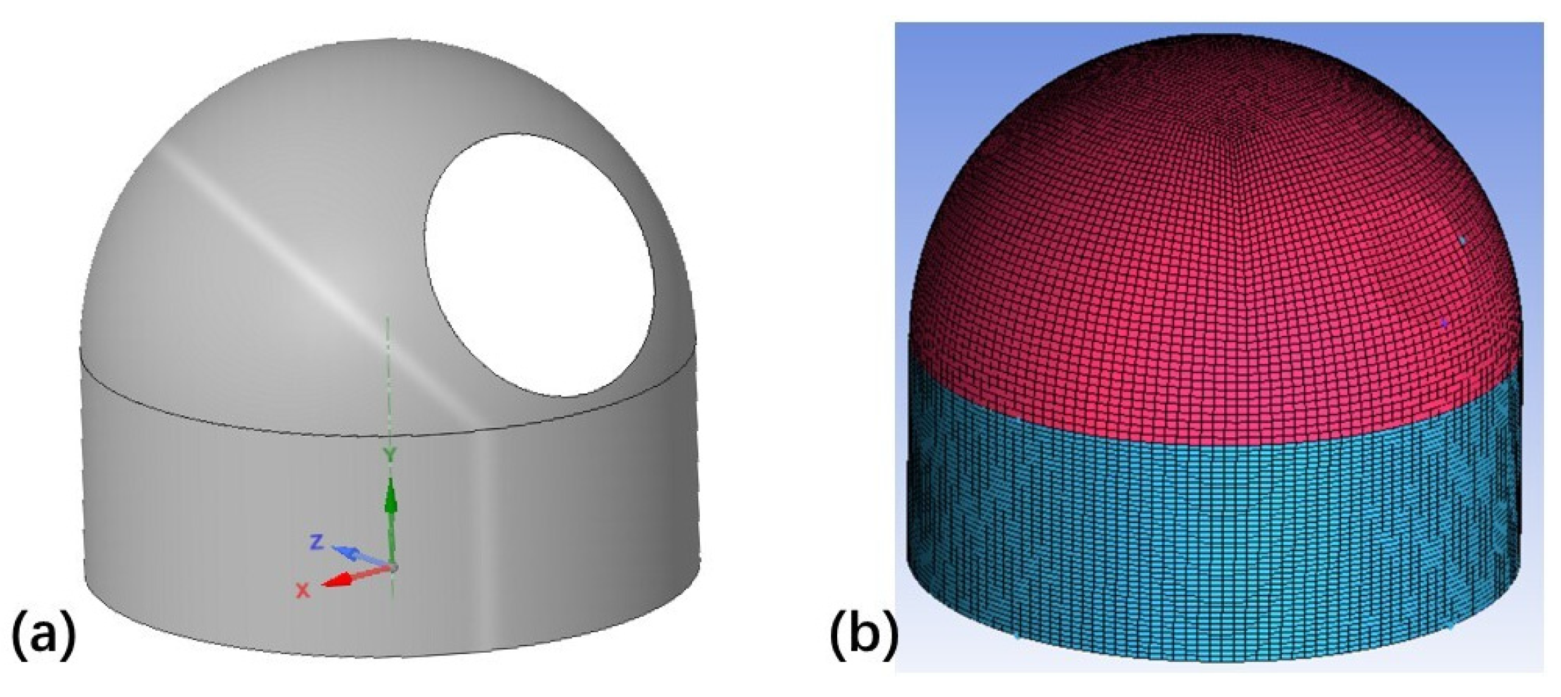
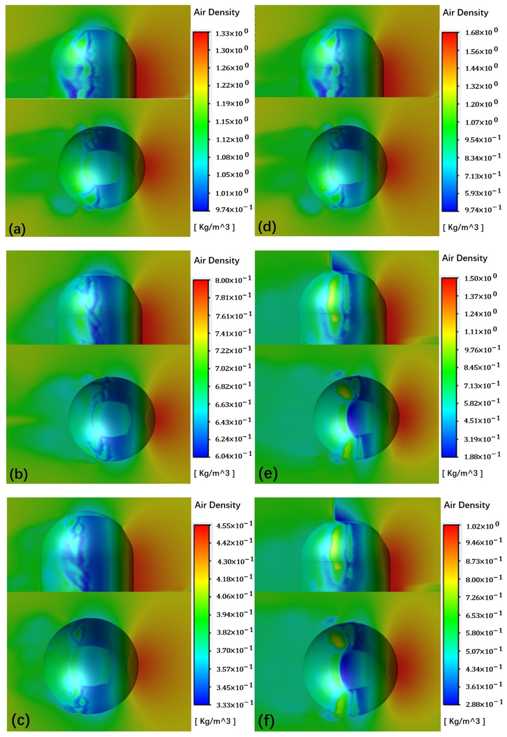
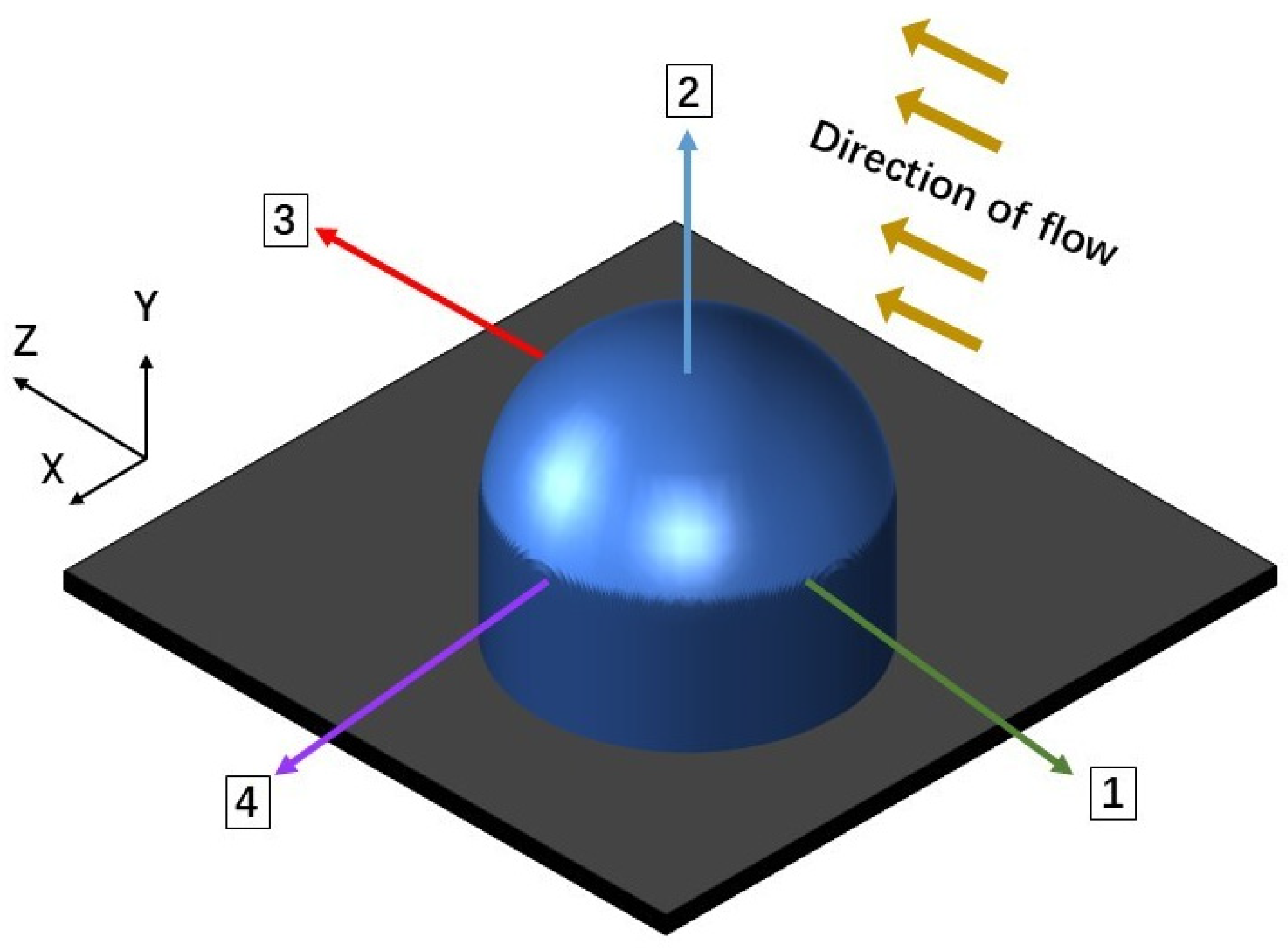
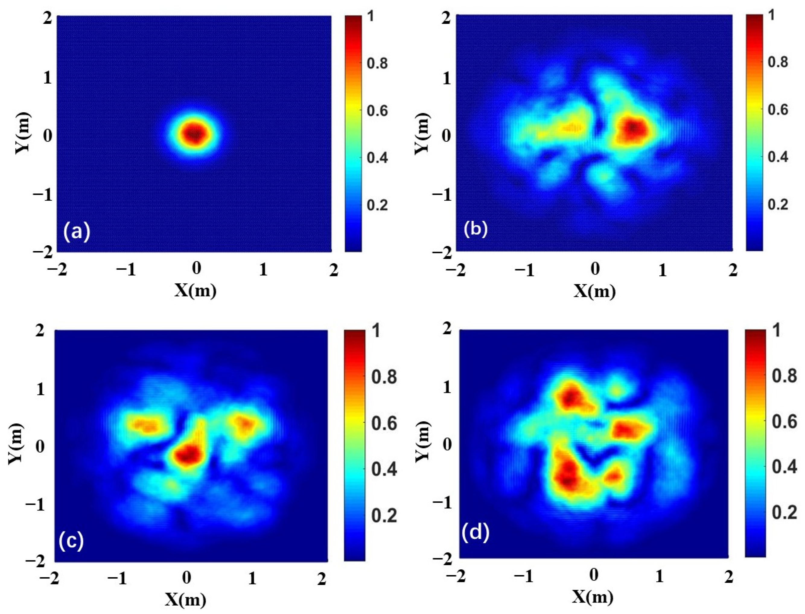
Simulation of Flow Fields and Beam Propagation

Under the flow field simulation conditions described in the previous section, the distribution of the air density near the optical turret is shown in Figure 2.
The density data obtained from the aforementioned flow field simulation are extracted, and the corresponding refractive index distribution is derived using Equation (1), with the wavelength of the optical beam being λ = 1550 nm. For the emission directions proposed in Equation (3), this study selected four typical emission angles, namely angles 1 to 4, as illustrated in Figure 3. Subsequently, the light field distribution is derived from Equations (4)–(6). Based on the phase distortion caused by flow field interference, corresponding phase screens are generated to filter the Gaussian beam, yielding the SNR expressed in Equation (8).
Utilizing the Monte Carlo phase screen method, a sequence of subsequent phase screens is generated based on Equation (9) to simulate the impact of atmospheric turbulence on beam propagation over long distances. Figure 4 displays the normalized intensity distribution of the light spot emitted in direction (2) under the combined influence of aero-optics and atmospheric turbulence at an altitude of 5 km and a velocity of 0.4 Ma.

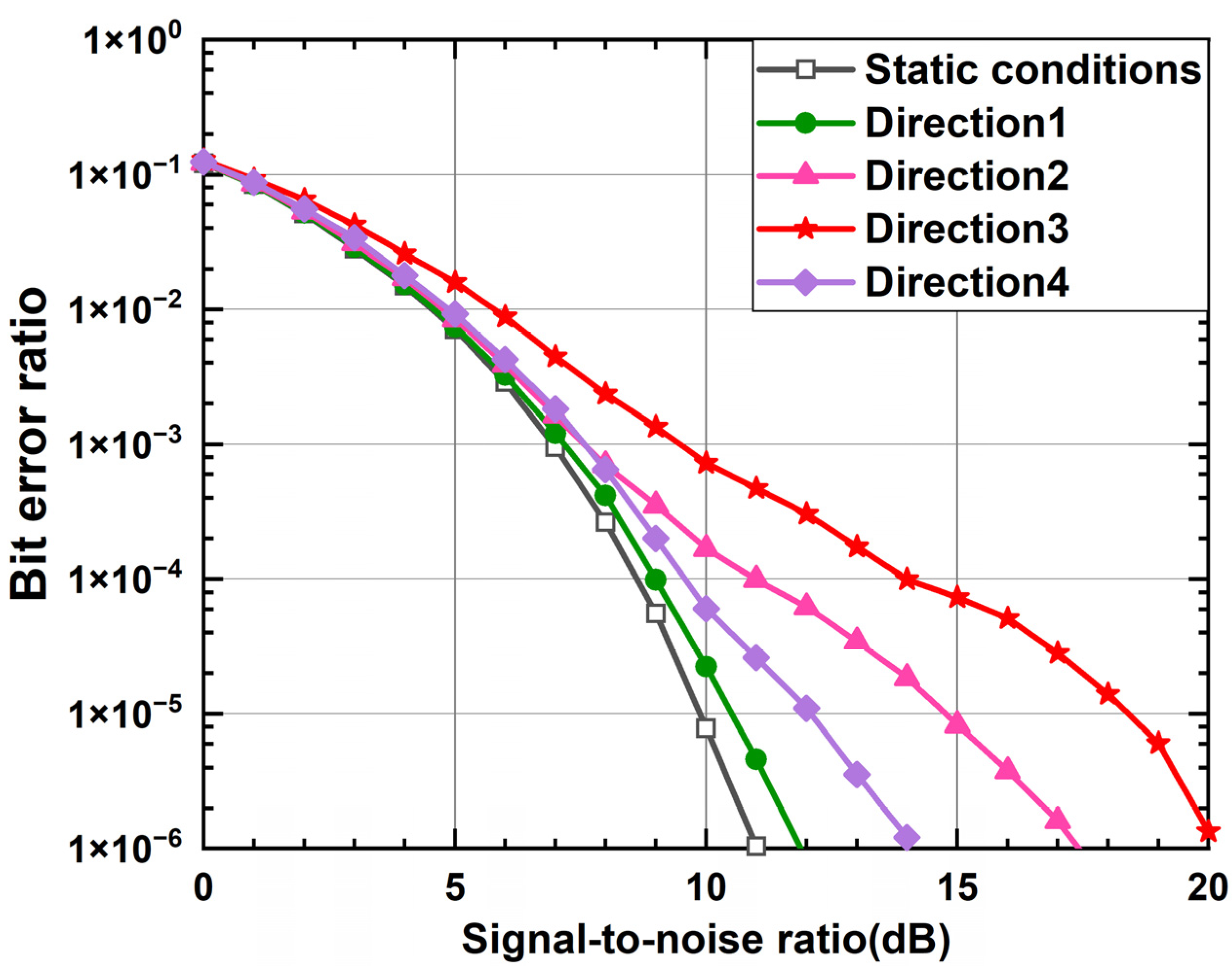
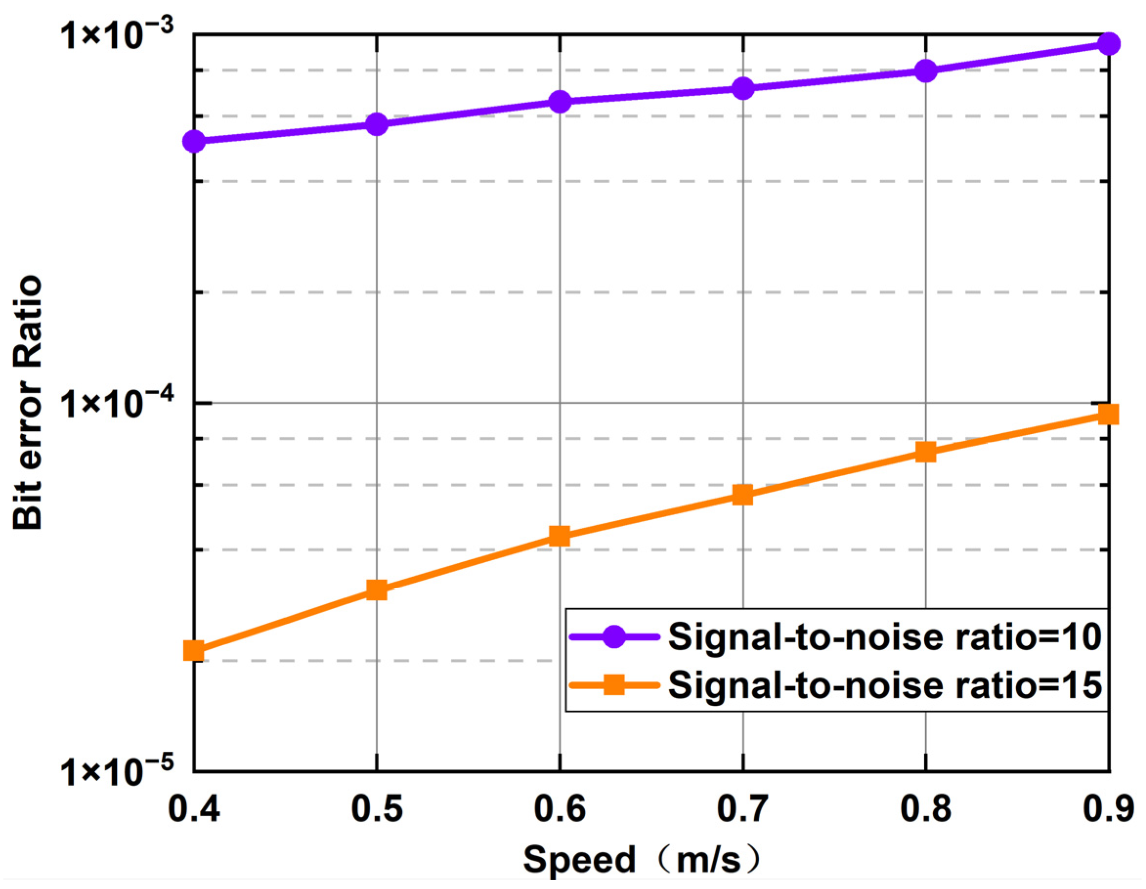
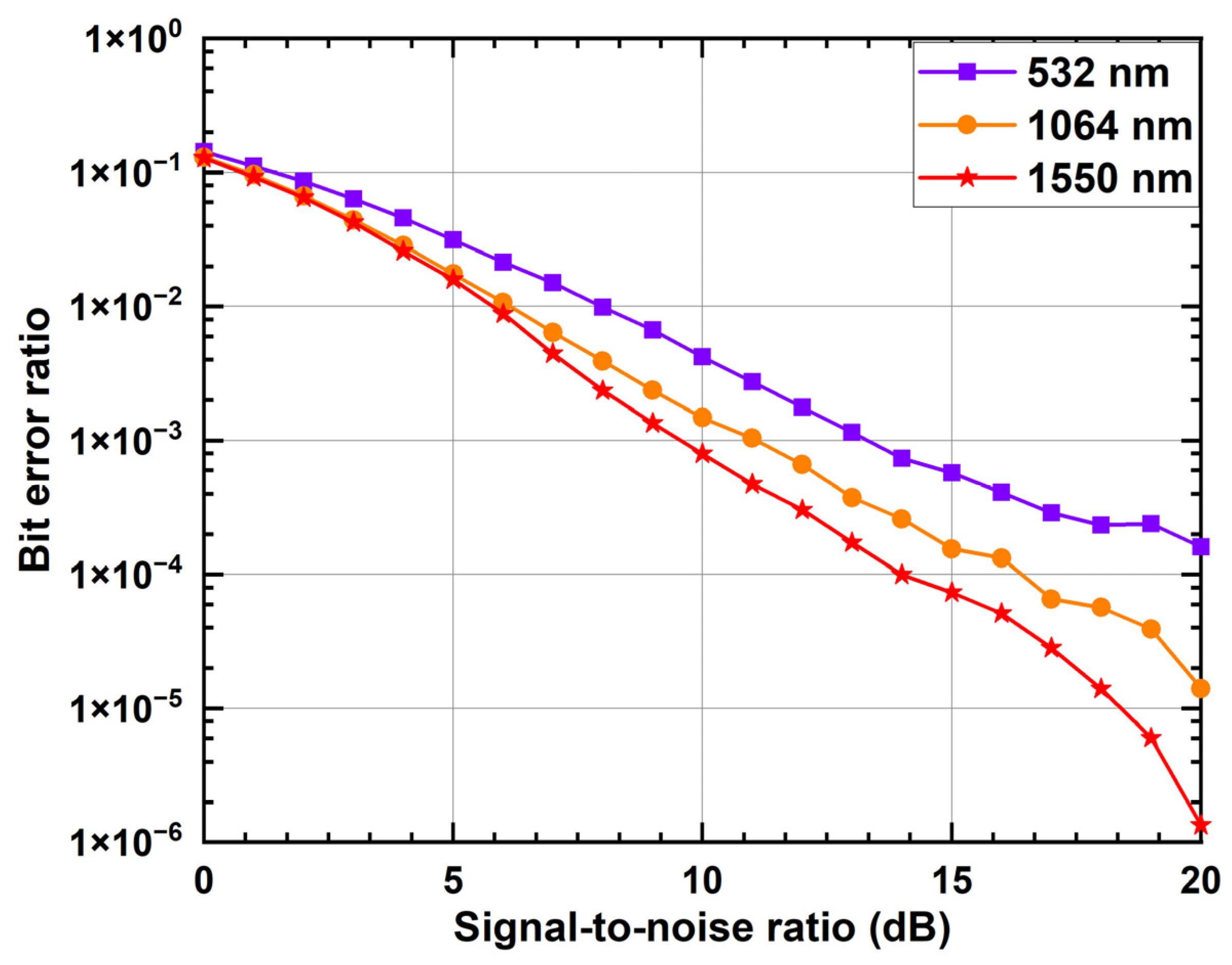
4. Simulation of Communication Performance

Following this, the Monte Carlo method is employed to generate the phase screens simulating the atmospheric turbulence-induced phase distortions, thereby facilitating the simulation of the error rate relationship expressed in Equation (11) and yielding insights into the evolving error rate trends of the airborne laser link. The atmospheric structure constant C n 2 is 5 × 10 15 m−2/3, and the transmission rate of the OOK signal is 5 Gb/s. At an altitude of h = 5 km and a speed of v = 0.4 Ma, Figure 5 depicts how the relationship between R B E R and R S N R aero varies as light propagates at different angles. From this graph, it is evident that, as R S N R aero increases, R B E R decreases accordingly. Under static conditions, the propagation of the beam is hardly affected by the directional airflow. Hence, it can be observed that aero-optical effects independently interfere with optical signals.
For instance, when the R S N R aero is 7.81 × 10 6 , the average R B E R is approximately 2.24 × 10 5 without aerodynamic optical disturbances. However, under the four typical angles specified in this study, the emitted beam along direction angle 1 experiences minimal density fluctuations in the flow field, resulting in slight variations in the refractive index and an R B E R of approximately 2.24 × 10 5 . Similar simulation results apply to direction 4, with an R B E R of approximately 6 . 04 × 10 5 . Conversely, the R B E R exceeds 1 × 10 4 for other directions under the same conditions.
Direction 2 is mainly considered for the following simulation since motion conditions have a significant impact on the changing of the light spot in that direction. Figure 6 illustrates the variation in the BER under various aircraft speeds, assuming a flying altitude of h = 5 km. The turret’s more intense compression effect on the air causes the corresponding average BER to increase dramatically at high speeds compared to low speeds. This makes the impact of moving conditions evident when compared to static situations.
Taking the flight speed as a single variable and fixing the SNR, the communication performance under the condition of the selected SNR is studied, in order to more intuitively portray the influence of motion speed on laser communication connection. The outcomes are displayed in Figure 7. The BER steadily rises as flight speed is increased. For every 0.1 Ma increase in flying speed, the SNR increases by around 0.87 × 10 4 when the SNR is 10 dB. When the SNR is high, the BER increases as the speed increases. For example, when the speed increases from 0.4 Ma to 0.5 Ma, the BER increases by approximately 1.4 × 10 5 ; however, the BER increases by just 1.02 × 10 5 when the speed increases from 0.8 Ma to 0.9 Ma. The simulation results indicate that, as the flight speed increases, the BER gradually rises. Moreover, under high SNR conditions, the influence of the flight speed on the communication performance becomes more pronounced.
The simulation results are shown in Figure 8, which shows how the BER varies with the SNR at various altitudes. The BER of laser communication systems operating at high altitudes is often lower than that at low altitudes because the static air density decreases with height. Compared to lower altitudes, the rarefied air at higher altitudes is more prone to compression, which causes more noticeable variations in air density with increasing flight speed. The BER threshold is considered to be 1 × 10 6 . At the altitude h = 10 km, the required SNR increases by approximately 3.5 dB as the moving speed increases from 0.4 Ma to 0.8 Ma. However, the required SNR increase is only approximately 2 dB at the altitude h = 5 km. Thus, it can be concluded that, during high-altitude flights, the effect of the aircraft speed on the airborne communication performance is more noticeable.
The communication performances are compared for several different communication light wavelengths under identical motion conditions, as shown in Figure 9. Formula (2) shows that KGD increases as the communication beam’s wavelength decreases. A higher KGD will also intensify the optical path change brought on by density fluctuations, increasing the degree of wavefront distortion and ultimately resulting in a further reduction in the beam’s communication quality under the same motion conditions.

5. Conclusions

A communication performance analysis method has been proposed, based on a numerical simulation of flow fields for widely used airborne laser communication systems. Using this method, the communication performance variation in laser links with different emission angles was analyzed under different motion speeds and flight altitudes. Under subsonic conditions, the system’s communication performance steadily declines as flight speed increases. For every 0.1 Ma increase in flight speed, the increase in BER is around 0.87 × 10 4 when the SNR is 10 dB. The system’s communication performance improves with an increasing flight altitude, but it also becomes more susceptible to variations in flight speed. For every 5 km increase in altitude, the BER drops to half of the initial rate when the SNR reaches 10 dB. The wavefront distortion of laser beams emitted in different directions varies. In contrast to existing models of airborne laser communication systems, our proposed model is based on a specialized flow field simulation and incorporates a full aerodynamic flow field structure, including boundary layer effects and other complex flows. To improve accuracy, the model can modify the simulation parameters based on various motion states. The proposed model serves as a theoretical foundation for the testing and implementation of laser communication links on aerial platforms.

Author Contributions

Conceptualization, X.Z. and S.G.; methodology, X.Z.; software, X.Z.; validation, Z.L. and H.W.; formal analysis, X.Z.; investigation, L.M. and K.D.; resources, X.Z.; data curation, Q.J.; writing—original draft preparation, X.Z.; writing—review and editing, S.G.; visualization, S.G.; supervision, Z.L. and S.G.; project administration, S.G.; funding acquisition, Z.L. All authors have read and agreed to the published version of the manuscript.

Funding

This work was supported by the National Natural Science Foundation of China (U2141231, 62375239) and the Zhejiang Provincial Natural Science Foundation (LDT23F04015F05).

Institutional Review Board Statement

Not applicable.

Informed Consent Statement

Not applicable.

Data Availability Statement

Data are contained within the article.

Conflicts of Interest

The authors declare no conflicts of interest.

References

  1. Liu, Y.; Tan, X.; Jia, J.; Dong, B.; Huang, C.; Luo, P.; Shi, J.; Chi, N.; Zhang, J. A Hybrid Millimeter-Wave and Free-Space-Optics Communication Architecture with Adaptive Diversity Combining and HARQ Techniques. Photonics 2023, 10, 1320. [Google Scholar] [CrossRef]
  2. Chen, J.; Huang, Y.; Cai, R.; Zheng, A.; Yu, Z.; Wang, T.; Liu, Z.; Gao, S. Free-space communication turbulence compensation by optical phase conjugation. IEEE Photonics J. 2020, 12, 1–11. [Google Scholar] [CrossRef]
  3. Bai, J.; Wan, X.; Arslan, E.; Zong, X. Global Solar Radiation and Its Interactions with Atmospheric Substances and Their Effects on Air Temperature Change in Ankara Province. Climate 2024, 12, 35. [Google Scholar] [CrossRef]
  4. Wang, K.; Meng, W. Computational Analysis of Aero-Optical Distortions by Flow over a Cylindrical Turret. AIAA J. 2016, 54, 1461–1471. [Google Scholar] [CrossRef]
  5. Jumper, E.J.; Fitzgerald, E.J. Recent advances in aero-optics. Prog. Aerosp. Sci. 2001, 37, 299–339. [Google Scholar] [CrossRef]
  6. Jiang, L.; Yu, X.; Wang, C.; Dai, T.; Dai, Z.; Tong, S. Analysis of imaging quality of new laser communication system on missile in the aerodynamic environment. J. Russ. Laser Res. 2021, 42, 210–218. [Google Scholar] [CrossRef]
  7. Zheng, A.R.; Huang, Y.; Gao, S.M. Modeling and spatial diversity-based receiving improvement of in-flight UAV FSO communication links. Appl. Sci. 2021, 11, 6365. [Google Scholar] [CrossRef]
  8. Dabiri, M.T.; Sadough, S.M.S.; Khalighi, M.A. Channel modeling and parameter optimization for hovering UAV-based free-space optical links. IEEE J. Sel. Areas Commun. 2018, 36, 2104–2113. [Google Scholar] [CrossRef]
  9. Lyke, S.D.; Voelz, D.G.; Roggemann, M.C. Probability density of aperture-averaged irradiance fluctuations for long range free space optical communication links. Appl. Opt. 2009, 48, 6511–6527. [Google Scholar] [CrossRef] [PubMed]
  10. Li, Y.; Mei, H.; Ye, S.; Tao, Z.; Deng, H.; Wu, X.; Rao, R. Spatial Fluctuations of Optical Turbulence Strength in a Laboratory Turbulence Simulator. Photonics 2024, 11, 229. [Google Scholar] [CrossRef]
  11. Ding, H.; Yi, S.; Zhu, Y.; He, L. Experimental investigation on aero-optics of supersonic turbulent boundary layers. Appl. Opt. 2017, 56, 7604–7610. [Google Scholar] [CrossRef] [PubMed]
  12. Ren, X.; Yu, H.; Yao, X. Passive fluidic control on aero-optics of transonic flow over turrets with rough walls. Phys. Fluids 2022, 34, 109–115. [Google Scholar] [CrossRef]
  13. Jacob, M.; Stanislav, G.; Nicholas, D.L.; Jumper, E.J. Shock-related effects on aero-optical environment for hemisphere-on-cylinder turrets at transonic speeds. Appl. Opt. 2017, 56, 4814–4824. [Google Scholar]
  14. Pond, J.E.; Sutton, G.W. Aero-Optic Performance of an Aircraft Forward-Facing Optical Turret. J. Aircr. 2006, 43, 600–607. [Google Scholar] [CrossRef]
  15. Beauchamp, R.L.; Fiorino, S.T. Propagation of laser light through aero-optic flow: Dry air at 0.4 Mach with three-dimensional turret. In Proceedings of the SPIE—The International Society for Optical Engineering, Baltimore, MD, USA, 23–27 April 2012; Volume 8380, p. 18. [Google Scholar]
  16. Yang, B.; Yu, H.; Liu, C.; Wei, X.; Fan, Z.; Miao, J. An Aero-Optical Effect Analysis Method in Hypersonic Turbulence Based on Photon Monte Carlo Simulation. Photonics 2023, 10, 172. [Google Scholar] [CrossRef]
  17. Kalensk, M.; Gordeyev, S.; Jumper, E.J. In-flight studies of aero optical distortions around AAOL-BC. In Proceedings of the AIAA Aviation 2019 Forum, Dallas, TX, USA, 17–21 June 2019; AIAA: Reston, VA, USA, 2019; p. 3253. [Google Scholar]
  18. Wayne, D.T.; Phillips, R.L.; Andrews, L.C.; Leclerc, T.; Sauer, P. Observation and Analysis of Aero-Optic Effects on the ORCA Laser Communication System. In Proceedings of the Atmospheric Propagation VIII, Orlando, FL, USA, 25–29 April 2011; SPIE: Bellingham, WA, USA, 2011; Volume 8038, pp. 101–112. [Google Scholar]
  19. Phillips, R.L.; Andrews, L.C. FSO communications: Atmospheric effects for an airborne backbone. In Proceedings of the Atmospheric Propagation V, Orlando, FL, USA, 16–20 March 2008; SPIE: Bellingham, WA, USA, 2008; Volume 6951, pp. 11–21. [Google Scholar]
  20. Zhao, J.; Zhao, S.; Zhao, W.; Cai, J.; Liu, Y.; Li, X. Probability of fade for airborne laser communication system over exponentiated Weibull distribution under aperture averaging. Opt. Rev. 2018, 25, 487–492. [Google Scholar]
  21. Sun, X.W.; Yang, X.L.; Liu, W. Aero-optical suppression for supersonic turbulent boundary layer. J. Turbul. 2021, 22, 1–25. [Google Scholar] [CrossRef]
  22. Ninos, M.P.; Nistazakis, H.E.; Sandalidis, H.G.; Stassinakis, A.N.; Tombras, G.S. Block error rate performance of OOK free-space optical links over gamma–gamma turbulence channels with generalized non-zero boresight pointing error. IET Optoelectron. 2018, 12, 269–272. [Google Scholar] [CrossRef]
  23. Chang, Y.; Liu, Z.; Yao, H.; Gao, S.; Dong, K.; Liu, S. Performance Analysis of Multi-Hop FSOC over Gamma-Gamma Turbulence and Random Fog with Generalized Pointing Errors. Photonics 2023, 10, 1240. [Google Scholar] [CrossRef]
  24. Zhao, J.; Zhao, S.H.; Zhao, W.H.; Cai, J.; Liu, Y.; Li, X. BER performance analysis of M-ary PPM over exponentiated Weibull distribution for airborne laser communications. J. Opt. Technol. 2017, 84, 658–663. [Google Scholar] [CrossRef]
Figure 1. Airborne turntable model. The turntable geometric model (a) and the turntable grid structure (b).
Photonics 11 00378 g001
Figure 2. Simulation results of the air density under different motion conditions. (a) h = 0 km, v = 0.4 Ma; (b) h = 5 km, v = 0.4 Ma; (c) h = 10 km, v = 0.4 Ma; (d) h = 0km, v = 0.8 Ma; (e) h = 5 km, v = 0.8 Ma; (f) h = 10 km, v = 0.8 Ma.
Photonics 11 00378 g002
Figure 3. Schematic diagram of the laser direction angle.
Photonics 11 00378 g003
Figure 4. Comparison of the spot distortion under different motion conditions. (a) v = 0 Ma; (b) v = 0.4 Ma; (c) v = 0.6 Ma; (d) v = 0.8 Ma.
Photonics 11 00378 g004
Figure 5. BER curves of different emitted angles under the flight conditions of h = 5 km and v = 0.4 Ma.
Photonics 11 00378 g005
Figure 6. BER curve for the communication performance under several typical moving speed conditions.
Photonics 11 00378 g006
Figure 7. Trend of the communication performance with the motion speed.
Photonics 11 00378 g007
Figure 8. Variation curve of the average BER as the SNR varies under different flight altitudes.
Photonics 11 00378 g008
Figure 9. Comparison of the communication performance of different wavelength communication beams under the same moving conditions.
Photonics 11 00378 g009
Table 1. Relationship between the temperature and the gauge pressure at different altitudes.
Altitude/kmTemperature/KStatic Pressure/Pa
0288.15101,325
5255.6754,048
10223.2526,499
Disclaimer/Publisher’s Note: The statements, opinions and data contained in all publications are solely those of the individual author(s) and contributor(s) and not of MDPI and/or the editor(s). MDPI and/or the editor(s) disclaim responsibility for any injury to people or property resulting from any ideas, methods, instructions or products referred to in the content.

