1. Introduction
Energy resource depletion is a global concern, causing severe environmental consequences. Fossil fuels, like coal, oil, and natural gas, release harmful pollutants, affecting human health, wildlife, and ecosystems. Burning these fuels contributes to climate change, rising temperatures, melting ice caps, and extreme weather events [
1,
2].
Transitioning towards renewable energy sources like solar, wind, hydropower, and geothermal is crucial to reduce reliance on finite resources and promote a greener future. Energy efficiency measures and responsible resource management are essential for mitigating environmental impacts. Global energy development should promote the widespread use of renewable energy sources, particularly in densely populated cities. Transitioning from non-renewable fuels like oil and coal to clean energy sources and natural gas is critical to climate change policy [
3,
4,
5,
6]. Renewable energy sources are expected to become the world’s leader in power generation by 2030 [
7,
8,
9].
The Fischer–Tropsch synthesis (FTS) technology represents a significant breakthrough in providing alternative energy sources to address the increasing global energy needs while prioritizing environmental sustainability [
10,
11,
12]. The FTS is a sophisticated liquefaction technique that simplifies the production of many premium and environmentally friendly fuels using natural gas and coal as raw materials. This process involves using a catalyst in a highly exothermic reaction [
13,
14]. Also, the FT synthesis process encompasses the manufacturing of numerous kinds of clean fuels as well [
5,
15,
16,
17,
18,
19]
Five prominent varieties deserve attention within the domain of multi-phase reactors that can facilitate exothermic processes. These include the bubble/slurry bubble column reactors, multi-tubular fixed reactors, fluidized reactors (both regular and circulating systems), and the micro-structured (channel) reactor [
20,
21,
22]. Fluidized bed reactors have been increasingly popular in the chemical and petrochemical industries due to their versatility in facilitating various processes, including FT, cooling systems, fluid catalytic cracking (FCC), solid coating systems, and drying processes [
23,
24]. These applications often involve high exothermic reactions, and, to prevent the excessive build-up of heat and to maintain an optimal reaction temperature, a bundle of heat-exchanging tubes is typically integrated into these reactors. This is made possible by the good solids mixing and high heat and mass transfer rates associated with fluidized bed reactors [
25,
26].
Effective heat management methods are necessary due to the high occurrence of extremely exothermic processes in these applications. The excessive build-up of heat can significantly impact the functioning of a reactor, potentially resulting in temperature runaway reactions, diminished product quality, and compromised safety. In order to address these concerns, it is imperative to utilize a bundle of heat-exchanging tubes within the reactors. This particular approach aids in mitigating the accumulation of excessive thermal energy and sustaining ideal conditions for chemical reactions. Notably, these reactors’ designs and scaling up frequently depend on empirical correlations established from experimental data acquired from fluidized beds that lack heat-exchanging tubes (i.e., empty columns) [
27,
28,
29]. The utilization of correlations and the extension of findings to fluidized beds containing a bundle of heat-exchanging tubes raises a relevant inquiry [
30,
31,
32,
33].
Designers favor using fluidized bed data without heat exchanging tubes in the design of such reactors due to its accessibility, availability, cost-effectiveness, and ability to yield conservative estimates. However, it may not fully capture complexities in reactors with heat-exchanging tubes. Therefore, there is a great need to conduct experimental studies to precisely evaluate the impact of heat-exchanging tubes on heat transfer rate.
The heat transfer rate within these reactors depends on many factors, among which the design and configuration of heat exchange tubes are paramount. For example, an investigation was conducted by Taofeeq et al. (2019) to examine the impact of the diameter of vertically immersed tubes on heat transfer within a gas–solid fluidized bed. The authors performed experiments utilizing a laboratory-scale fluidized bed column and fast-response heat transfer probes. It has been discovered that enhancing the heat transfer performance within a gas–solid fluidized bed can be achieved by increasing the diameter of the vertically submerged tube [
34]. Hasan et al. (2022) recently used an advanced heat transfer technique to measure the local and instantaneous heat transfer coefficient for different tube bundle designs, including square-pitch and triangular-pitch arrangements. The results showed that the square-pitch tube arrangement exhibited a significant increase and uniformity in heat transfer coefficient when measured instantaneously compared with other tube arrangements. They also found that the heat transfer coefficient was enhanced when the axial positions increased for all radial positions [
27].
Prior studies have emphasized the significance of tube diameter and bundle design to heat transfer efficiency, setting the stage for further extensive investigations in this particular area of inquiry. However, it is important to mention that previous studies commonly utilized tube bundles with flat ends. Tube ends, often overlooked in traditional reactor designs, have recently emerged as a focal point for potential enhancements in heat transfer performance.
Therefore, this study aims to evaluate and measure the influence of utilizing tapered and flat end shapes on local and instantaneous heat transfer coefficients in different operating conditions. Our goal is to shed light on the potential improvements that could result from selectively altering the shape of tube ends, using the most recent heat transfer technique.
By quantifying local and instantaneous heat transfer coefficients under varying conditions, we seek to unlock novel routes for improving reactor efficiency and environmental sustainability in generating renewable energy domination. Additionally, this study exhibits potential for researchers and scholars seeking to progress the discipline and for engineers and designers endeavoring to develop more effective reactor designs. Moreover, this study enhances the fundamental comprehension of heat transfer in intricate reactor systems. Furthermore, the data generated from this work will be of great value in developing and validating sophisticated models, hence enhancing the optimization of fluidized bed reactor operations [
35,
36].
2. Experimental Work
2.1. Experimental Setup
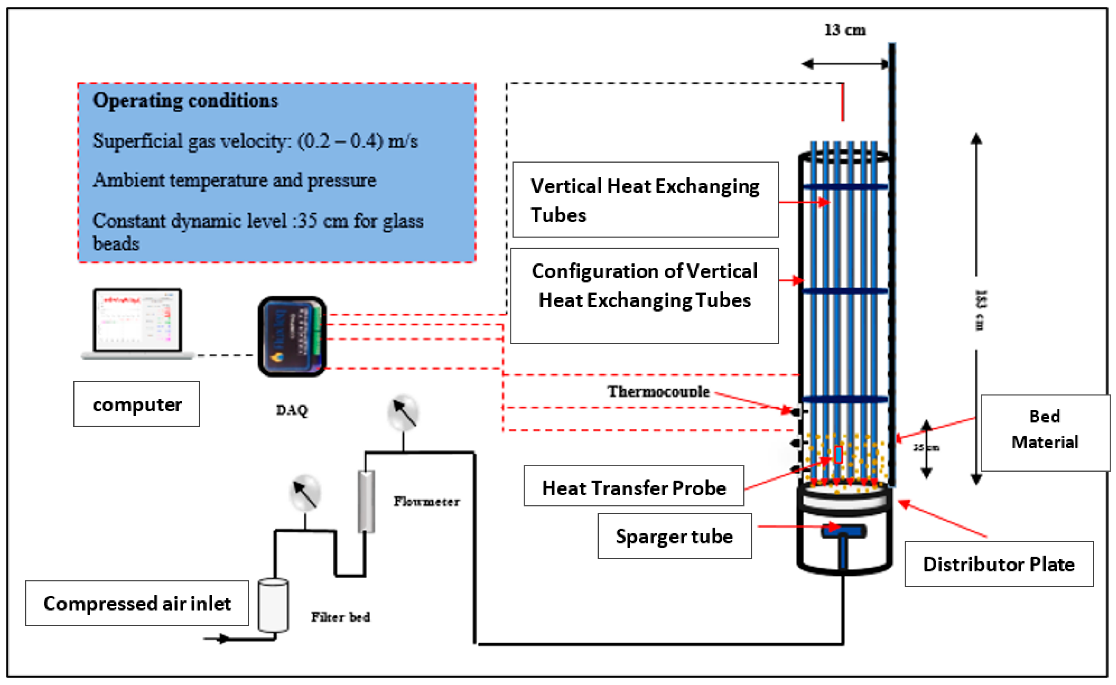
A fluidized bed column was specifically developed to systematically investigate the impact of tube end shapes on the local heat transfer coefficient under different operating conditions. The height of the column measured 1.83 m, whereas its diameter was 0.13 m, as depicted in
Figure 1. In addition, the column was equipped with thirty stainless steel tubes, with dimensions of 1.93 m in height and 0.012 m in diameter. These tubes occupied a quarter of the cross-sectional area of the fluidized bed column to simulate an industrial FT reactor. A tapered-shaped end was fabricated utilizing a 3D printer and securely attached using a high-quality adhesive. This was performed to evaluate the influence of end shapes on the heat transfer coefficient in square tube configurations, as illustrated in
Figure 2.
Before air was introduced into the calibration flowmeter, the compressed air underwent a process of filtration and drying. A flowmeter was chosen to monitor the necessary flow rates on an industrial level, encompassing various flow regimes such as churn turbulent, slugging, and bubbling. Subsequently, the desiccated air was delivered into the column via a 30 cm plenum and guided through the gas distributor.
The gas (air) distributor employed in this investigation was fabricated using polyethylene, a permeable substance, having a thickness of 0.127 cm. The distributor plate was specifically engineered to facilitate consistent air distribution while simultaneously providing structural support for the weight of the bed. The distance between the lower extremity of the heat-exchanging vertical tubes, and the distributor plate was maintained at 10 cm.
The experimental data collection involved a diverse set of air velocities, spanning from 0.2 to 0.4 m/sec. The primary objective of this extensive inquiry was to assess the influence of different tube end designs on the local heat transfer coefficient (LHTC). The heat-exchanging tube bundle area was determined by considering the free cross-sectional area (CSA). This enabled the computation of gas velocities, as demonstrated by the following relationship [
27,
37,
38]:
2.2. Advanced Heat Transfer Measurement Technique in a Fluidized Bed Reactor
In recent years, notable technological breakthroughs have expanded the domain of possibilities in terms of real-time monitoring of heat transfer and the local heat transfer coefficient (LHTC) with enhanced sensitivity. The advancement in heat flux sensor technology played a crucial role in this study by facilitating accurate measurement of local heat transfer coefficients (LHTC) within a fluidized bed column that contained a bundle of tubes. The local heat transfer Coefficient (LHTC) was a fundamental metric that plays a crucial role in comprehending heat transfer phenomena within the scope of this study. It aided in acquiring valuable insights into the effectiveness of heat exchange mechanisms.
This measurement technique entailed the application of a solid brass component with dimensions of 8 cm in length and 12 mm in diameter, together with a cartridge heater, a heat flux sensor (PHFS), and two Teflon components. The first step involved the creation of a chamber within the brass component to accommodate the cartridge heater. Subsequently, the cartridge heater was carefully inserted into the cavity inside the brass piece. Following this, the PHFS heat flux sensor was affixed onto the outside surface of the brass component by epoxy glue in order to quantify heat flux precisely. In order to mitigate thermal dissipation and uphold a regulated atmosphere, two Teflon segments were employed to secure the upper and lower regions of the brass plate. Comprehensive information on the manufacturing process for the heat transfer technique may be found in the scholarly publication authored by Zahraa et al. [
27,
38].
The placement of the heat transfer probe within the column was crucial for data acquisition. The proposed non-invasive technique involved the insertion of a probe into a singular tube inside the tube bundle. This probe interfaced with a vertical heat exchanger and was then incrementally pushed radially around the diameter of the column. Implementing this setup guaranteed the continuous monitoring of LHTC while minimizing any disruption to the flow dynamics within the column.
In addition, type T thermocouples were utilized to acquire bulk temperature data at various positions along the probe as shown in
Figure 3. As mentioned earlier, the measurements offered significant data for the research, aiding in characterizing temperature patterns within the column.
The acquisition and logging of data, such as heat flux measurements from PHFS and integrated temperature signals, were performed using the ComPAQ Instrument for Acquisition system for heat flux and thermocouple data. Implementing this integrated system facilitated the collection of data-gathering procedures, enhancing the precision and uniformity of the experiment. Further elaboration regarding this configuration can be found in the scholarly work authored by Zahraa et al. [
27,
38].
In brief, the heat transfer measurement technique utilized in this investigation utilized state-of-the-art heat flux sensor technology to precisely assess local heat transfer coefficients (LHTC) within a fluidized bed column housing a bundle of tubes. In conjunction with bulk temperature measurements, this non-invasive technique offered a thorough understanding of heat transfer phenomena.
2.3. The Reproducibility and Uncertainty Analysis of Heat Transfer Technique Measurements
The instantaneous determination of the local heat transfer coefficient (LHTC) was achieved through the utilization of a heat flux sensor (HFS) to monitor the heat flow while considering the disparity in temperature between the bulk and surface temperatures, as prescribed by Newton’s equation [
27,
38].
Here, ℎi represents the instantaneous LHTC (W/m2·°C), hav is the time-averaged heat transfer coefficient, qi denotes the instantaneous heat flux (W/m2), Tsi is the surface temperature (instantaneous), and Tbavg is the instantaneous bulk temperature. The sample size (n) for each measurement consisted of 250 sampled data points at a rate of 750 Hz.
The analysis of heat transfer coefficient measurements conducted on the first and second days provided valuable insights regarding the replicability and dependability of the experimental findings. The observations were of utmost importance in evaluating the accuracy of the heat transfer method utilized in this research.
Figure 4 exhibits the measured heat transfer coefficient under different operating superficial gas velocities for the first and second days (i.e., the data measured at different times).
It can be seen from the figure that, at lower surface gas velocities, ranging from 0.2 m/s to 0.28 m/s, the differences seen between measurements conducted on the two separate days are very minimal, generally falling below 2%. The observed consistency in the data indicates a substantial likelihood of reproducibility within the specified velocity range, hence suggesting the possibility of achieving reliable measurements. Moreover, error analysis indicates that the error bars for these measurements were calculated to be less than 5%, further underlining their reliability.
Nevertheless, when the surface gas velocity reached 0.32 m/s and exceeded this threshold, the differences between measurements conducted on various days became more noticeable, with certain cases exhibiting percentage variances above 4%. However, the percentage of differences was still minimal. This confirmed that measurements had smaller error bars, which suggested a decrease in uncertainty.
The heat transfer process demonstrated exceptional reproducibility and dependability at lower gas velocities, as evidenced by the modest percentage changes and low error bars. Identifying and resolving the factors contributing to this heightened variability was of utmost importance to improve the dependability of measurements under these circumstances and guarantee the precision of forthcoming experimental investigations.
Each measurement in the study was conducted using a sample size (n) of 250 data points sampled at a rate of 750 Hz. The primary objective of this sampling approach was to guarantee a high level of repeatability and measurement reliability under various operating situations, as illustrated in
Figure 4.
In order to improve the reproducibility of measurements, a minimum of three experimental runs were undertaken, thereby mitigating the potential influence of purposeful sampling on the measurements. In order to mitigate potential sources of error in the experimental process, the results section exclusively presents the mean values of the heat transfer coefficient. Additionally, error bars were computed below 5% for each measurement, showing a limited degree of variability.
It is crucial to acknowledge that the time-averaged heat transfer coefficient for the advanced heat transfer probe at each position was determined by calculating the average of the instantaneous heat transfer coefficient readings obtained throughout the 300-s sampling intervals employed in each experimental trial. This rigorous methodology guaranteed the reliability and accuracy of the measurements while also considering the inherent uncertainty associated with the obtained data.
3. Results and Discussion
The LHTC was presented instantaneously using a new version of data acquisition instruments, demonstrating promising results regarding the effects of the tubes’ end shapes in enhancing the effectiveness of heat transport and reactor operation.
3.1. Impact of Superficial Gas Velocity on LHTC for Tapered End Shape
Figure 5 presents the heat transfer coefficients (HTC) observed in a fluidized bed column’s wall and center areas, with varied superficial gas velocities. Significantly, it can be shown that there is a general increase in the heat transfer coefficients in both locations when the superficial gas velocity rises from 0.2 m/s to 0.4 m/s, as shown in
Figure 6. For instance, at all radial positions (±0.58, ±0.03) along the diameter of the column, the LHTC for the cone end shape between the regions of middle and wall was increased by 38.59%, 30.1%, 27.69%, 31.019%, 29.09%, and 33.98% from 0.2 to 0.4 m/s.
The heat transfer coefficient (HTC) within the wall region exhibits its minimum value of 105.72 W/m2·°C when the gas velocity is 0.2 m/s. The observed value increase as gas velocities increase can be attributed to the enhanced gas flow, which facilitates improved mixing and heat transfer between the solid particles and the gas in this specific location. Likewise, within the central region, the heat transfer coefficient (HTC) commences at a value of 171.53 W/m2·°C when the gas velocity is 0.2 m/s. Furthermore, it exhibits an ascending pattern as the gas velocities increase. The observed behavior can be linked to the increased circulation of particles and improved heat transfer, which is helped by higher gas velocities.
It is worth noting that the heat transfer coefficients in the central region continuously exceed those in the wall region across all gas velocities, indicating variations in particle concentrations and flow patterns between these locations. In conclusion, the data presented in these figures indicate that increasing the superficial gas velocity in the fluidized bed column improves heat transfer. This finding has significant implications for optimizing reactor designs and processes that rely on efficient heat transfer.
In summary, the evidence underscores the significance of superficial gas velocity and tube end shape in impacting heat transfer coefficients within a fluidized bed column. The aforementioned findings provide helpful information that can be utilized to optimize reactor designs and operations that necessitate efficient heat transfer.
3.2. Quantifying the Impact of Radial Position and Superficial Gas Velocity on Heat Transfer Coefficients
The data in
Figure 7 demonstrate the fluctuations in heat transfer coefficients (HTC) at different radial locations within a fluidized bed column, including a bundle of heat-exchanging tubes with tapered ends. These variations occur as a result of changes in superficial gas velocities.
The impact of radial locations on heat transfer coefficients is evident. A significant differentiation becomes apparent when contrasting the heat transfer coefficient at the central region of the column (0.03) with that at the wall (−0.58). For example, at a superficial gas velocity of 0.2 m/s, the heat transfer coefficient (HTC) at the center exceeds that at the wall by approximately 65%. The observed difference decreases as the gas velocity increases, yet it remains a significant phenomenon.
The quantification of the impact of superficial gas velocity on the heat transfer coefficient (HTC) is feasible. An observable increase in heat transfer coefficient (HTC), averaging around 26% across all radial positions, is observed when the gas velocity is increased from 0.2 m/s to 0.4 m/s. This observation provides evidence of a clear and positive relationship between gas velocity and heat transfer efficiency.
The importance of radial position is further emphasized by examining the variance in HTC (heat transfer coefficient) at different positions for each flow velocity. As an example, when the superficial gas velocity is 0.2 m/s, the heat transfer coefficient (HTC) at the center (0.03) exceeds the HTC near the wall (−0.58) by approximately 57%.
The quantifications above emphasize the complex characteristics of heat transmission in fluidized beds. The relationship between the radial location and gas velocity gives rise to significant variations in heat transfer coefficients, which requires careful attention from engineers and researchers involved in designing and optimizing fluidized bed reactors.
In order to optimize heat transmission in real-world scenarios, it is crucial to recognize and measure these factors. Engineers can utilize these quantifications to customize the designs and operational parameters of fluidized bed reactors to meet specific objectives, ultimately aiming to improve energy efficiency and reactor performance.
To conclude, assessing the impact of radial location and superficial gas velocity on heat transfer coefficients emphasizes the crucial requirement for a thorough understanding of these factors in the context of fluidized bed systems. This knowledge serves as a significant resource, enabling well-informed decision-making about the design and operation of reactors, ultimately promoting increased efficiency and effectiveness in industrial operations.
3.3. Comparison of Different Tube end Shapes at High Superficial Gas Velocities on Heat Transfer Coefficient
Figure 8 and
Figure 9 present the local heat transfer coefficient (LHTC) instantaneous signals at a superficial gas velocity of 0.4 m/s near the wall (−0.58) and at an axial height of 1.923. These signals correspond to square-pitch tube configurations, including distinct end tube shapes, namely, tapered and flat ends.
When analyzing the performance of LHTC (local heat transfer coefficient) in relation to different tube end forms, a recurring pattern becomes evident, wherein the tapered end shape regularly exhibits superior performance compared to other shapes under diverse operating situations. For example, when the superficial gas velocity is 0.4 m/s, the local heat transfer coefficient (LHTC) for the tapered end form is roughly 20% greater than that for the flat end shape.
The enhanced efficacy of the tapered end configuration can be ascribed to the specific design characteristics and arrangement of the vertical heat exchange tubes. The tapered-shaped end design facilitates enhanced heat transfer efficiency by influencing flow patterns, turbulence effects, and fluid dynamics within the fluidized bed. The progressive enlargement of the tapered configuration facilitates a more streamlined fluid flow, resulting in decreased turbulence and improved thermal interaction between the solid particles and the fluid. Consequently, this leads to an enhancement in the overall efficiency of heat transfer.
The constant pattern seen in our study, wherein the tapered end shape consistently demonstrates superior performance in LHTC across various operating circumstances, supports our research objective. For example, at a superficial gas velocity of 0.4 m/s, it is seen that the tapered end form demonstrates a significant 20% increase in the local heat transfer coefficient (LHTC) when compared to the flat end design. The quantifying of the performance disparity underscores the practical significance of our research outcomes. The tapered configuration of the end shape is also a critical factor in enhancing the efficiency of solid mixing and circulation within the fluidized bed. The tapered end design minimizes particle stagnation and promotes the interface between solid particles and the fluid by decreasing dead zones and promoting a more uniform distribution of solid particles. The enhanced blending results in increased efficacy of heat transmission mechanisms.
The implementation of the tapered end form ultimately results in enhanced energy efficiency within fluidized bed reactors. The reactor can more efficiently attain its intended temperature and reaction conditions by enhancing heat transmission mechanisms, optimizing solid mixing processes, and improving fluid dynamics. The observed efficiency has noteworthy consequences for industrial processes, decreasing energy consumption and operational expenditures.
In conclusion, the findings of our investigation emphasize the significant importance of tube end shape within the framework of fluidized bed reactors. Through illuminating the benefits of the tapered end shape and presenting quantitative evidence of its enhanced performance, we provide significant insights for engineers and researchers who aim to customize fluidized bed reactor designs and optimize operating conditions. The acquisition of this knowledge possesses the capacity to facilitate significant enhancements in energy efficiency and overall reactor performance.
4. Conclusions
In summary, this research sheds light on the significant impact of tube end shapes, superficial gas velocity, and radial positioning on heat transfer coefficients in fluidized bed reactors. The results of this study offer measurable insights that can be utilized to enhance reactors’ design and operational efficiency.
Tapered tube end configurations have been empirically proven to significantly improve energy efficiency in fluidized bed reactors. At a superficial gas velocity of 0.4 m/s, the tapered end form’s local heat transfer coefficient (LHTC) demonstrated a significant 20% enhancement compared to the flat end shape. This apparent enhancement facilitates precisely manipulating temperature and reaction parameters within these reactors.
The acquisition of this knowledge holds significant value for professionals in engineering, research, and design, as it can generate considerable advantages. Engineers have the potential to use these results in order to enhance reactor performance, decrease energy consumption, and foster the development of sustainable energy generation.
Moreover, the data produced in this work represents a significant asset for advancing and verifying sophisticated computational models. These models enable the optimization of fluidized bed reactor operations with more precision, potentially resulting in decreased operational expenses and improved overall reactor efficacy.
Regarding future research, it would be beneficial for scholars further to investigate the impacts of different tube end configurations, extending beyond the commonly studied tapered and flat ends. Further exploration of intricate geometries or non-traditional designs may yield further insights towards improving heat transfer in fluidized bed reactors.

 ,
, 
