Abstract
Porous medium models are commonly used in Computational Fluid Dynamics (CFD) to simulate flow through permeable screens of various types. However, the setup of these models is often limited to replicating a pressure drop in cases where fluid inflow is orthogonal to the screen. In this work, a porous medium formulation that employs a non-diagonal Forchheimer tensor is presented. This formulation is capable of reproducing both the pressure drop and flow deflection under varying inflow angles for complex screen geometries. A general method to determine the porous model coefficients valid for both diagonal and non-diagonal Forchheimer tensors is proposed. The coefficients are calculated using a nonlinear least-squares optimisation based on an analytical solution of a special case of the Navier–Stokes equations. The applicability of the proposed method is evaluated in four different scenarios supplemented by local CFD simulations of permeable screens: wire mesh, perforated screens, air louvers, and expanded mesh panels. The practical application of this method is demonstrated in the modelling of windbreaks and permeable double-skin facades, which typically employ the aforementioned types of porous screens.
1. Introduction
Permeable screens are often employed as wind-shielding devices: these can be used as free-standing porous elements or they can be adopted in bridges to realise wind breakers. More recently, porous panels have been employed in buildings as cladding elements with a wide variety of installation contexts: these include their usage as the outer cladding layer, placed at a certain distance from the inner wall, realising the so-called double skin façades [1,2]. For those cases, it is expected that the wind-interaction of such permeable elements depends on its installation context within the building or bridge and on the free-standing aerodynamics of the mesh itself, usually dictated by geometrical details of a much smaller scale than the structure itself. This difference in scale introduces unique challenges in designing civil structures with permeable elements. A purely experimental approach, based on wind tunnel tests, with scaled models is limited by the multi-scale nature of the problem: the main limitation lies in the representation of the porous elements in the scaled model and in the possibility of pressure sensor placement on such elements to measure pressure fluctuations [3]. A recent promising alternative for wind load estimation is represented by Computational Fluid Dynamics (CFD) simulations, specifically the ones employing Large Eddy Simulation models: several studies [4,5] assess its potential application in building design, allowing for a direct estimate of design pressure values. Additionally, it is currently a standard practice to complement wind tunnel tests with CFD simulations to obtain additional information on the flow characteristics around and inside large-scale civil structures [6]. This is especially true for coupled and decoupled thermodynamic simulations [7].
When referring to large-scale permeable screens in the CFD framework, relying on a model which includes all geometrical details of porous structures would result in unattainable computational requirements. However, there exists the possibility to model such screens using a macroscopic representation through a porous-media approach. An advantage of this is the possibility to model the porous medium in most modern “off-the-shelf” CFD packages. This avoids an explicit modelling of porous layer geometry or an introduction of a custom code to the CFD solver. Even though this is a viable strategy to assess wind interaction with permeable façades or windbreak barriers, the application of a porous-media approach in this specific contexts is still in its early stages of research and the number of studies on the topic is currently limited [8,9]. This is, not in the least, due to the lack of a well-established methodology to compute the coefficients governing the porous-media model, that characterise porous structures and reflect the flow interaction on a macroscopic scale.
Porous-media models have been otherwise widely used and experimentally verified in other application fields, such as ocean engineering and ventilation systems design, with different methodologies for the computation of the input coefficients, as discussed in the next section.
1.1. Current Modelling Practice
A macroscopic description of the porous structure can be realised as a 2D surface with zero thickness or as a 3D volume. When the former is used, the method is usually referred to as a porous baffle. A porous baffle relies on a pressure-jump condition to realise the resistance source [10], while both approaches use the Darcy–Forchheimer formulation to define an additional source term in the momentum equations, the latter defines the resistance source through a tensorial term. As a consequence, it is (at least theoretically) able to describe isotropic or anisotropic porous medium characteristics [11].
A porous baffle is typically characterised by a porous resistance that acts normal to the baffle surface and is defined by two scalar Darcy–Forchheimer resistance coefficients ( and , respectively). This approach is typically used to model very thin membranes [12] or permeable windbreak barriers [13,14,15,16]. However, as shown by the experiments conducted by [17], in the case of inclined perforated screens, the pressure drop is not always proportional solely to the normal component of the flow, and therefore cannot be defined by scalar resistance coefficients. This fact has been recently addressed in [18,19], in which the authors proposed a custom pressure–velocity jump condition to model permeable surfaces.
In cases when a volumetric porous medium is adopted, the question of how to set coefficients for the other two directions (, and , ) in the resistance tensor arises. In practice, CFD modellers (such as [20,21]) often set these coefficients related to the non-orthogonal components of the flow to some values that are several orders of magnitude higher than and . Such an approach is erroneous as discussed in Section 2.4. Conversely, in [22], only the normal component of the flow is considered when establishing the value of the resistance coefficients, essentially resulting in = . In fact, this lack of clarity about the role of the resistance coefficients in characterising permeable screen macro behaviours leads the authors of [23] to recommend the use of isotropic coefficients ( = ) as they compare the performance of porous baffles to volumetric porous media with isotropic and orthotropic resistance coefficients, without sufficient insight on the differences in behaviour of the models considered on the fundamental level. (Note: The orthotropic formulation in the mentioned work applies resistance only in the direction normal to the sheet surfaces, i.e., = .)
The authors of [24], while modelling air louvers, also propose to set and to rotate the porous medium reference frame such that the x-axis is aligned with the slut tilt angle. This approach is dubious, as the rotation of a reference frame will not preserve translational periodicity. Meanwhile, ref. [25] proposed empirical relations to derive resistance coefficients. However, no in-depth investigation on the behaviour of louvers under varying inflow conditions was presented. In fact, in cases of flow incoming at high angles of attack, the difference in velocities between the porous media model and the resolved geometry was as high as 38%.
At the same time, in the field of ocean engineering, while modelling thin permeable structures, such as fishing nets, the authors of [26,27,28] rely on a simplified analytical model that assumes a linear relationship between the total forces experienced by the nets and the Darcy–Forchheimer coefficients. The coefficients are obtained by a least-squares fit of total forces obtained from the simplified model to the experimental data or high-fidelity CFD simulations. This approach provides meaningful resistance coefficients and is similar to the method proposed in the present paper. The major difference is that the analytical formulation presented in this paper is derived by solving a system of non-linear differential equations describing the flow through a porous medium.
On the topic of selecting the porous resistance coefficients without the availability of high fidelity simulations or experimental tests, ref. [29] proposes an approach valid for fishing nets, based on the transformation of the Morison-type load model. This approach can be adopted for wired mesh panels, while more complex geometries still rely on experimental results and empirical relationships derived from them.
Thus, based on the current modelling practice, there is no rigorous framework that allows CFD modellers to connect Darcy–Forchheimer resistance coefficients to the macroscopic behaviour of complex permeable screens. The overwhelming majority of existing works consider only the pressure drop in the case of fluid inflow orthogonal to the screen. This is also reflected in the experimental set-ups used to characterise these screens. The permeable panels, if tested in the wind tunnel, are placed in wall-bounded flow conditions. In rare cases where the effect of the inclination is tested [17], the panel remains in the wall-bounded flow. In such a set-up, the flow deflection cannot be possibly measured, and the total pressure drop is affected by the imposed boundary condition. Meanwhile, the approach proposed by [26], in the context of modelling fishing nets, while taking into account the effect of inflow angles of attack, can only be adopted for wired meshes and perforated screens. An extension of this approach is required to model screens with more complex geometries.
1.2. Research Scope
As discussed above, employing porous medium models is not a novel approach. This approach has been, at least partially, validated through the experimental results in certain set-ups. However, there is little to no rigorous research on the selection of porous model coefficients such as to replicate macro-scale screen behaviour not only in terms of permeability but also in terms of flow deflection (or equivalently, in terms of forces experienced by a portion of the screen). Moreover, as will be discussed in the following sections, modelling certain types of permeable screens such as air louvers and expanded mesh panels is not possible within the current porous medium framework and requires the introduction of extradiagonal terms to the Forchheimer tensor. Therefore, it is fundamental for a new modelling framework to meet the following requirements:
- -
- Exhibit similar macro behaviour (pressure drop and flow deflection) to the permeable screen under varying inflow conditions, i.e., for different angles of attack.
- -
- Capture the inherent lack of symmetry for complex geometries such as expanded meshes.
- -
- Provide a possibility to evaluate resistance coefficients using geometry resolved CFD or wind tunnel test results.
The aim of the present paper is twofold. Firstly, it is intended to introduce a general method to compute the coefficients for the porous-media approach. Secondly, it is to propose an application of such methodology in modelling of typical geometries of permeable cladding panels with the adoption of a non-diagonal Forchheimer tensor. In addition, this study aims to establish the necessary basis for the use of the porous-media model as a design tool for permeable cladding within the CFD framework. It is given that this would ultimately require the adoption of unsteady approaches to perform full-scale simulations with incoming turbulent atmospheric boundary layer. Nevertheless, it is essential to guarantee the capability of the porous-media model to reflect the complex flow interaction with porous panels, foremost with a steady state assumption. Hence, this paper assess the applicability of the proposed methodology from a practical point of view though an application of porous medium models in steady state simulations of permeable cladding panels such as wired meshes, perforated panels, expanded metal mesh panels and air louvers (Figure 1).
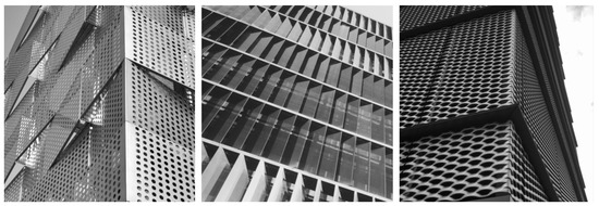
Figure 1.
Permeable screen types on building facades: perforated screens, louvers, expanded mesh (left to right).
- Perforated cladding panels and wire mesh
The main characteristic of these panels is the presence of multiple planes of symmetry. As discussed in Section 2.4, this greatly simplifies the modelling of such screens.
- Louvers and expanded metal mesh cladding
Unlike perforated cladding, air louvers and expanded mesh panels have only one plane of symmetry. These panels introduce a significant flow deflection also in cases of inflow normal to the screen. Expanded mesh panels are most geometrically complex.
1.3. Paper Organisation
In Section 2, the theoretical basis for the modelling framework is established, and the method to evaluate Forchheimer resistance coefficients is presented. In particular, Section 2.2 introduces a porous medium formulation with non-diagonal Forchheimer tensor along with the derived analytical solutions, and Section 2.4 lists the necessary steps to obtain Forchheimer resistance tensor coefficients, such that porous media exhibit the same macro-behaviour as permeable screens. Moreover, some practical conclusions about resistance coefficients for the four major typologies of permeable screens are drawn based on the analytical derivations. Then, in Section 3, the practical applicability of the proposed method is discussed. The setup of geometry-resolved CFD simulations is presented in Section 3.1, while the equivalent porous volume counterparts are presented in Section 3.2. In Section 4, the proposed method is applied to evaluate resistance coefficients in the case of four major typologies of permeable screens. The results are discussed in terms of correspondence of the analytical solutions to the ones obtained from CFD solvers, and, generally, in terms of porous model capabilities and limitations. Finally, overall conclusions are drawn in Section 5 along with an indication of possible future research.
2. Evaluation of Forchheimer Coefficients
2.1. Darcy–Forchheimer Formulation
In the case of presence of porous medium, the Navier–Stokes Equation is modified by adding a source (or rather “sink”) term on the right-hand side based on Darcy–Forchheimer law.
Conventionally, d and f are diagonal matrices. The first term of Equation (1) can be dropped, if the viscous stresses can be neglected. This is a valid simplification for modelling windscreens on building facades or windbreaks as a porous medium. The forces exerted on these screens are dominated by the resultant of pressure field integration, rather than by viscous stresses. Additionally, it is reasonable to start with a steady state assumption as the atmospheric boundary layer turbulence scale is much larger than a permeable screen characteristic length, i.e., the size of the openings. Thus, assuming inviscid and incompressible steady state flow, the governing equation becomes
2.2. Non-Diagonal Forchheimer Tensor Formulation
Equation (2) can be used to model the flow through a perforated screen; however, in the case of air louvers and expanded mesh due to inherent lack of symmetry, two extra-diagonal terms need to be introduced, as follows, starting with a more general definition:
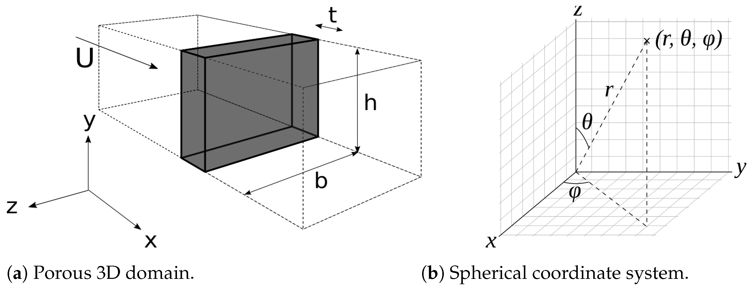
In the case of porous screens, it is possible to assume a porous zone infinite in two directions, neglecting the effect of borders. This is true to some extent also for air louvers. The computational domain can be represented as in Figure 2a. The x-axis is aligned to the normal of the screen/porous volume and the panel extends in y- and z- (tangential) directions. In this configuration, for incompressible flow, the pressure gradient is present only in the x-direction, due to momentum conservation. Thus, Equation (3) can be simplified to
where , while and are constant. In this case, the f tensor is a 3 × 3. Each coefficient in this setup relates i-th component of the force experienced by the porous screen due to the j-th component of the fluid velocity vector. Louvers and expanded mesh panels have a mirror symmetry with respect to the xy plane. The introduction of non-null coefficients , , , would break the symmetry. For instance, the forces and should be same for and . Conversely, is different for and for porous screens that are not symmetric with respect to xz plane. Moreover, the incoming flow is deflected in the y-direction. These considerations necessitate the definition of and coefficients.
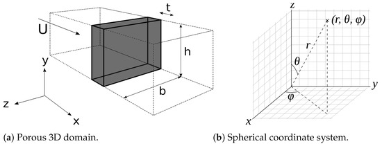
Figure 2.
Computational domain and coordinate systems.
The solution of Equation (5) is still not straightforward. To further simplify the problem, two different flow conditions are considered:
- Case 1
The first case implies , resulting in a 2D flow through the porous screen in the xy-plane, described by
The analytical solution for , thus, can be decoupled from the rest of the system. It is a hyperbolic function, presented here in its exponential form. With defined, it is possible to solve for p.
defining the following:
- , ;
- , ;
- , are integration constants obtained by imposing proper boundary conditions.
- Case 2
The second case is a particular 3D flow through the porous screen, which does not introduce any change to (i.e., is null). In Case 2, both and are constant throughout the entire domain. From Equation (5), it is clear that this is possible for some combinations of and , i.e., only for some inflow conditions.
Writing Equation (9) in the spherical coordinate system defined in Figure 2b,
In this case, can be simply computed as
defining
- ;
- is the integration constant obtained by imposing suitable boundary conditions.
The analytical solutions of the pressure and flow fields derived above are exact, given the inviscid, incompressible, and steady-state assumption. Thus, a CFD finite-volume solver employing a porous medium though a Forchheimer sink term is expected to provide the same results. Therefore, these solutions create a link between the Forchheimer coefficients and the macroscopic behaviour of the porous model. The goal is, therefore, to match this macroscopic behaviour to that of an actual screen. However, the measurement of pressure drop and flow deflection in a wind tunnel setup (rather than a local geometry resolved CFD simulation) is rather challenging. Meanwhile, it is much more straightforward to measure total forces experienced by a portion of a screen, with force-balance devices.
2.3. Forces on the Permeable Screen
Total porous forces (equivalently the forces experienced by a portion of a permeable screen) can be obtained using a Control Volume (CV):
where
- is computed integrating forces acting throughout CV such as gravity;
- ;
- is computed integrating the viscous stresses on the Control Surface (CS).
Rearranging Equation (13) to solve for and applying the aforementioned simplifications by disregarding gravitational and viscous forces in an incompressible steady flow, total porous resistance can be computed as follows:
In the specific case of a cyclic domain (Figure 2a),
where h, b, and t are the CV dimensions for the permeable screen/equivalent porous media considered.
2.4. Resistance Tensor Coefficients
Assuming that the forces on a permeable screen can be obtained either from high-fidelity CFD simulation or from wind tunnel tests, the resistance coefficients can be computed by solving a nonlinear least-squares optimisation problem. The implementation itself is straightforward [30], and the general procedure can be summarised in the Algorithm 1.
| Algorithm 1: A Method to Evaluate Forchheimer Tensor |
Input: with and with Result: , , , ,
|
It should be noted that steps 3 and 4 are necessary only for the definition of porous coefficients in the case of expanded meshes, as explained further. Before proceeding with the implementation of the proposed modified porosity model, several observations can be pointed out in relation to the f resistance tensor coefficients.
- Perforated plates and wired meshes
In the case of perforated plates and wired meshes, due to the double symmetry, = , resulting in a diagonal f tensor. Therefore, perforated plates and wired meshes can be modelled using standard porous theory equations. Moreover, wired meshes and some perforated plates also have a rotational symmetry around the x-axis. In these cases, = .
A common mistake in the modelling of these objects is to set , to high values by arguing that the panel itself is not permeable in these directions (see [20,21]). However, from Equation (7), one can observe that as for any and . Therefore, such a porous panel would align the flow to its normal, regardless of the inflow angles. This describes the behaviour of a perforated plate with thickness t much larger than the perforation dimension. Only in this case would one expect the outflow to always be aligned with the x-direction.
On the contrary, most perforated plates introduce only slight deflections to the incoming flow at an angle with respect to the normal. As a result, , are often of an order of magnitude lower than . An extreme case is that of an infinitely thin plate, often referred to as “baffle”. Such a model is not expected to introduce any noticeable flow deflections regardless of the inflow condition. From Equation (5), it is clear that such behaviour for a volumetric porous medium is possible only with = . This fact should be recognised, when neglecting tangential resistance coefficients, as was considered for instance in [23].
- Air louvers
Air louvers are not expected to introduce flow deflections in the xz-plane, and therefore, . As mentioned before, both, and will be non-null. Generally, is not equal to (see Section 4), and therefore, the resistance tensor cannot be diagonalised, as suggested by [24].
- Expanded mesh
Expanded meshes introduce a slight flow deflections in xz-plane; however, as will be shown in the following chapters, the is usually an order of magnitude less compared to the other two components. Consequently, plays a minor role in describing the behaviour of these objects.
3. CFD Simulations Setup for Method Applicability Study
Many modern CFD solvers have the ability to model porous regions. Before performing the applicability study of the proposed methods and assessing the capability of the porous model to simulate the flow past screens in practical problems, OpenFOAM and Fluent finite volume method (FVM) solver results were compared against the analytical solution. Both solvers are widely used in the industry and yielded results consistent with the solution derived in Section 2. To implement the modified sink term with a non-diagonal resistance tensor, some changes to the code are required. In the case of OpenFOAM, these code changes have been described in [31]. Meanwhile, the most recent version of Fluent allows users to directly implement source terms in the properties of the fluid region.
3.1. Resolved Geometry CFD Simulations
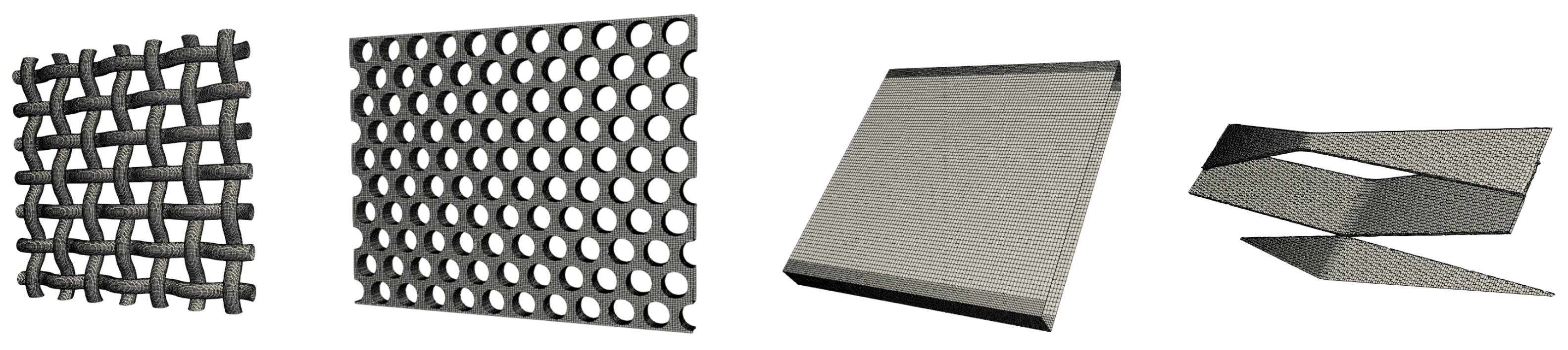
To assess the applicability of the proposed method in practice and explore the limitations of the porous model, in general, the authors utilised available CFD simulations performed in the past on the portions of the wire mesh, perforated screens, and expanded mesh. These simulations provided realistic (albeit possibly not precise) sets of forces experienced by permeable screens under various inflow conditions. A detailed description of the resolved CFD simulations can be found in previous publications [11,31]. In addition, a model with louver geometry was prepared to complete the demonstration of practical use cases. Forces obtained from medium/high-fidelity simulations were used to characterise equivalent porous mediums as described by Algorithm 1.
- Geometry and Domain
All resolved geometry simulations modelled a portion of a permeable screen (see Figure 3) placed in a rectangular-shaped domain as shown in Figure 2a. Their main geometrical characteristics are as follows:
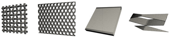
Figure 3.
Resolved portions of the permeable screens.
- -
- Wire mesh: wire diameter 4 [] with 6 [] × 6 [] square openings.
- -
- Perforated panel: hole diameter 6 [], porosity 50%.
- -
- Louvers: plate 150 [] × 15 [], tilt angle.
- -
- Expanded mesh: opening 250 [] long and 50 [] wide.
To represent an infinitely extended screens, periodic boundary conditions are applied to the lateral surfaces. Null pressure condition is enforced at the outlet, while the velocity vector of 10 m/s magnitude and null pressure gradient are specified for the inlet for all simulations. Table 1 summarises the dimensions of the computational domains for the resolved geometry CFD models.

Table 1.
Computational domain section for resolved geometry and porous volume simulations.
- Numerical setup and validation of resolved geometry models
Resolved geometry CFD simulations were performed adopting steady state solvers and RANS ( and ) turbulence models. The detailed numerical set-up can be found in [11,31]. Meanwhile, rigorous performance evaluation of the resolved geometry models lies outside the scope of this paper. This work does not seek to answer the question whether a CFD simulation can reproduce the flow through a given permeable screen using a geometry resolved model. The performance of the porous models is also not a focus of this study. The algorithm described in Section 2.4 minimises the least-square error between any set of forces provided by a geometry resolved simulation (or wind tunnel measurements) and the values attainable from the analytical solution. Therefore, the question of the true value of forces experienced by the permeable panel should be answered separately in each specific case. This can be achieved by performing verification and validation through wind tunnel testing or uncertainty quantification. The following cases are employed merely as a demonstration of the proposed method to evaluate resistance coefficients. They do, however, indicate that the simplified porous model, in principle, is capable of exhibiting the same macro-physical behaviour as a permeable screen.
3.2. Porous Volume CFD Simulations
In these simulations, the characteristics of an equivalent porous medium are set up following the Algorithm 1 so as to exhibit the same macro behaviour as the resolved geometry counterparts. In cases with a non-diagonal resistance tensor, the porous formulation cannot be used “as is” in OpenFOAM or Ansys Fluent. A modified OpenFOAM solver was previously used in [11,31]. On the other hand, Ansys Fluent allows a user to define custom source terms as defined by Equation (5) in the properties of the fluid region. The reader can refer to the user manual for practical implementation.
- Geometry and Domain
The computational domain for all the porous volume simulations was the same as the one for their resolved geometry counterpart (see Table 1). Naturally, the solid regions representing the resolved geometry of the screens were replaced with a porous volume. The thickness of the porous volume can be arbitrary and is limited only by the desired discretisation. Nevertheless, the resistance coefficients in the Forchheimer tensor are defined per unit of length, and therefore, the thickness should be fixed before performing the least square optimisation to the total forces. In this study, porous volume thickness for all the simulations was chosen at .
- Numerical Setup
The numerical simulations have been performed using steady-state solvers with RANS turbulence models. However, as noted before, the current framework does not address viscous and turbulence effects. Hence, an inviscid solver provided similar results. The adoption of the RANS solvers, nevertheless, is necessary in practical simulations such as the case of porous façades which are simulated together with the building itself. Neglecting the porous volume effects on the turbulent flow likely may lead to an underestimation of turbulence in the permeable screen wake, but it is reasonable to assume that it will have a minor contribution to the macro flow characteristics. A second order differentiation scheme has been adopted across all simulations.
In terms of discretisation, a structured mesh with hexahedron elements with a characteristic size of 0.05 m has been adopted. Additional tests with coarser and finer meshes showed little sensitivity to the mesh refinement, with the bare minimum requirement of three elements across the thickness of the porous zone. It is important to remark that, in the case of OpenFOAM, the initial testing showed the necessity to significantly reduce the size of the cells in the x-direction next to the porous zone interfaces. This allows us to achieve results consistent with the general theory. The reasons for such behaviour are most likely related to the interpolation of the values at the cell faces and particular implementation of the porous solver.
4. Results and Discussion
4.1. Perforated Panels and Wired Mesh
In this section, the proposed method is discussed in application to the modelling of wire meshes and perforated panels. Additionally, three different cases of perforated plates with plate thicknesses of 0, 2 and 4 mm were considered.
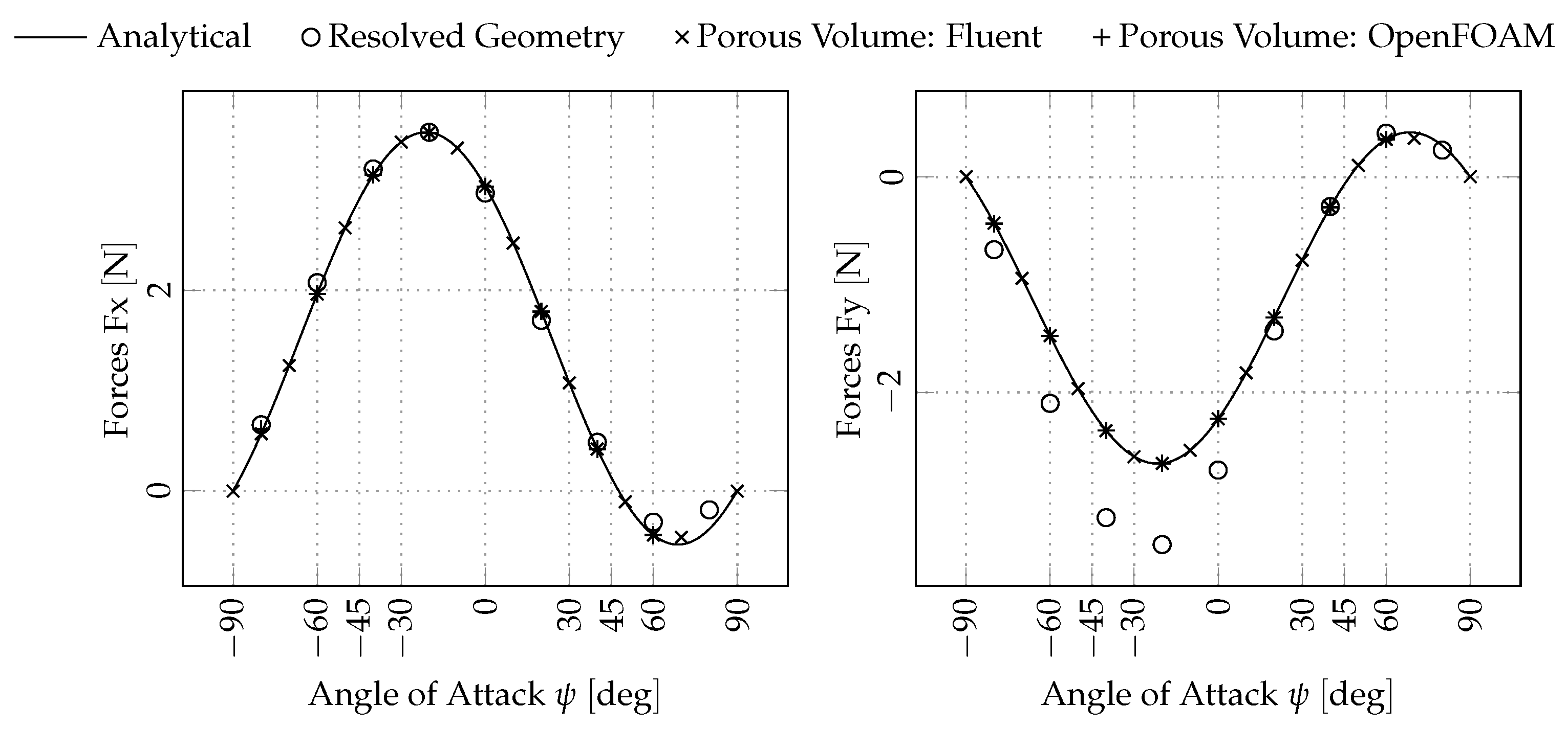
In general, for these geometries, Case 2 flow is equivalent to Case 1, as can also be deduced from the analytical solutions. As discussed in Section 2.4, due to double mirror symmetry, the resistance tensor is diagonal, and rotational symmetry implies . In fact, due to the xz-plane mirror symmetry, is even and is odd, as can be observed in Figure 4 and Figure 5.
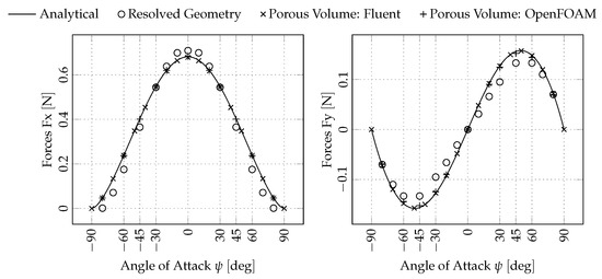
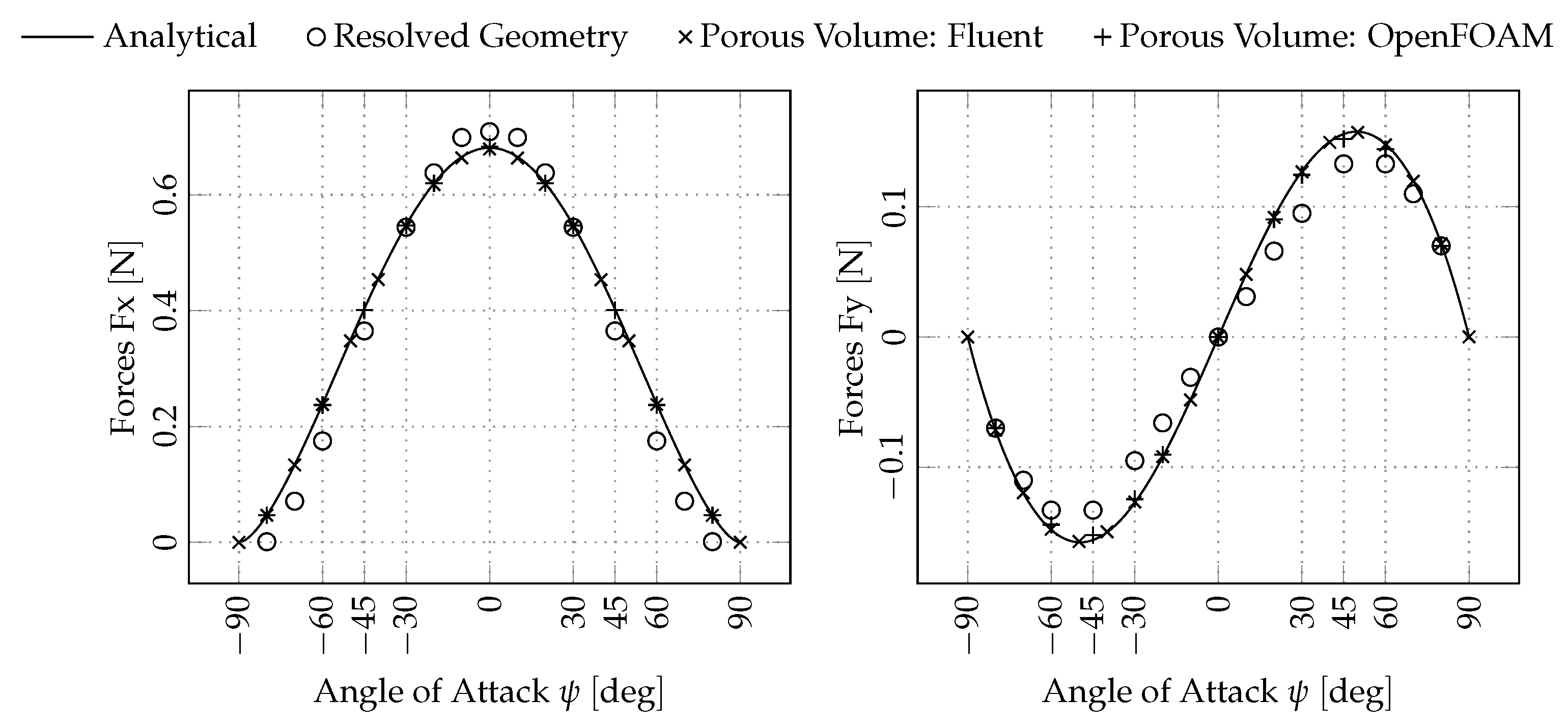
Figure 4.
Wired mesh: analytical, FVM porous vs. resolved geometry CFD solutions in the Case 1 flow.

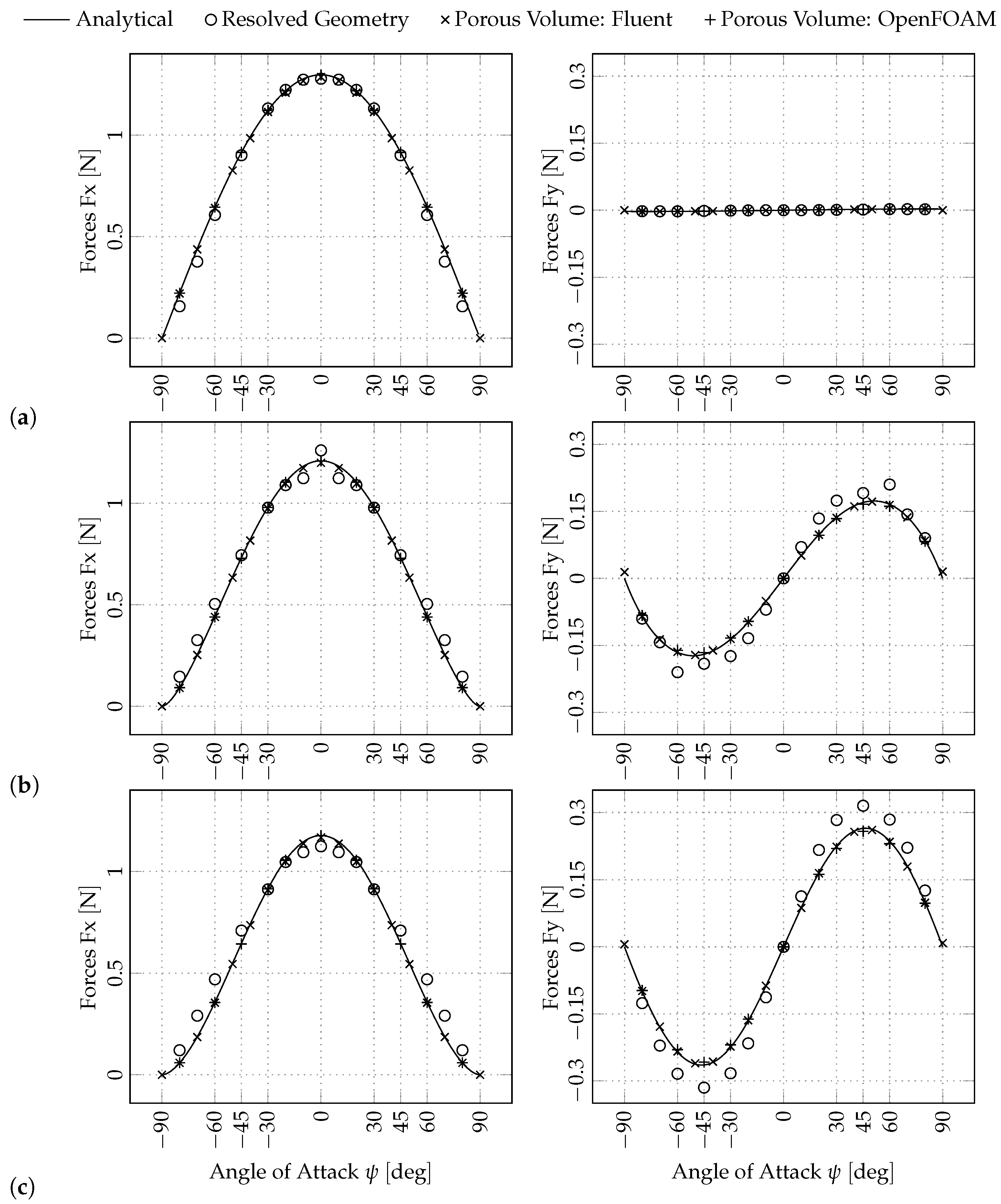
Figure 5.
Perforated panels: analytical, FVM porous vs. resolved geometry CFD solutions in the Case 1 flow; (a) 0 mm thickness, (b) 2 mm thickness, (c) 4 mm thickness.
- Wired mesh
Given the set of forces obtained from a CFD simulation of a wire mesh, the optimisation algorithm resulted in the following resistance tensor:
The overall macro-behaviour of the wire mesh was captured reasonably well by a porous model, as can be observed in Figure 4. FVM solvers provided results consistent with the analytical solution, as in the benchmark cases. However, there is no combination of coefficients that would result in a porous volume that exhibited exactly the same behaviour as the one observed in the resolved geometry model. In practice, the porous model did not match a steep gradient of at increasing angles of attack. This gradient would be possible only with a significant increase in the value of coefficient and consequently overestimation of the . Naturally, the least-squares error optimisation provided a “middle ground”. The resistance coefficients were set in a way to underestimate at small and overestimate at higher angles of attack. To fully assess the potential of the porous model in terms of accuracy, however, uncertainty should be quantified for the resolved geometry results.
- Perforated Panel, 0 mm thickness
Resolved geometry simulations of a perforated plate with null thickness show a negligible compared to (see Figure 5a). Consequently, in a resulting optimisation term dominates the resistance tensor. For such an idealised geometry, it is reasonable to assume a porous jump.
- Perforated Panel, 2 mm thickness
A perforated panel with a non-null thickness introduces resistance in the y direction due to the component of the flow, as can be observed in Figure 5b. As a result, the component of the resistance tensor is no longer null.
In this instance, the porous model also managed to reproduce the macro-behaviour of the resolved case rather closely. The sets of forces seem to have several outliers. This did not pose a problem for optimisation, as the remaining data outweighed the inconsistent readings.
- Perforated Panel, 4 mm thickness
An increase in thickness of the the perforated plates resulted in a higher forces, and consequently, the optimisation algorithm returned higher value of the coefficient. The fit of the porous model to the resolved geometry CFD results is not as good as in the other two perforated plate cases. The problem is opposite to the wire mesh case, resulting in a slight underestimation of and at high angles of attack.
The results discussed above illustrate the importance of a proper set-up of the and resistance coefficients. As can be observed in Figure 5, even relatively thin perforated plates experience a non-negligible force in the tangential direction at high angles of attack. This results in an incoming flow deflection that cannot be captured by a porous model if the resistance coefficients are not chosen properly. At the same time, the effect of these resistance coefficients on the pressure drop (as seen from ) is not as pronounced. As discussed previously, it is expected that a plate with a thickness much greater than its perforation size can be modelled by setting and coefficients to values that are several orders of magnitude higher than .
4.2. Louvers
This case is presented in Figure 6. In contrast to the previous cases of perforated panels and wired mesh, the is no longer and even function. Furthermore, as expected, is no longer null, as the incoming flow is deflected by the louvers. The resulting resistance tensor is the following:
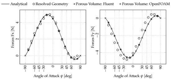
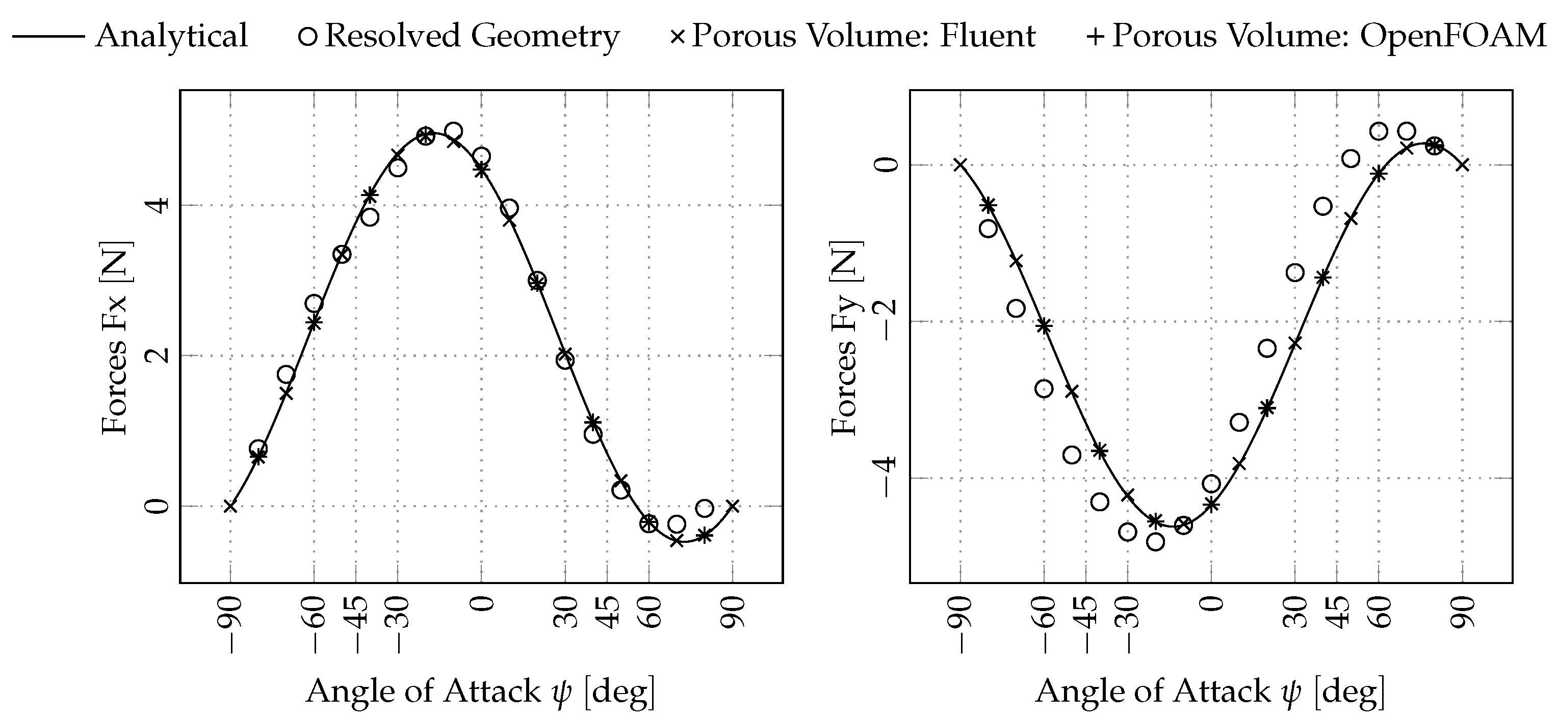
Figure 6.
Louvers: analytical, FVM porous vs. resolved geometry CFD solutions in the Case 1 flow.
As can be observed, in Figure 6, the porous model managed to capture the behaviour of (and, therefore, of a pressure drop), while there was no solution that would closely match the observed (related to flow deflection). The former is shifted by a constant value towards lower angles of attack.
It is not clear whether this observed behaviour is a limitation of the porous model itself in representing a particular permeable screen typology or it is a result of uncertainty in forces obtained from the resolved geometry CFD simulation. This issue is related to a correct estimation of the lift force generated by an array of louvers.
4.3. Expanded Mesh Panels
Figure 7 reports the behaviour of expanded mesh and its porous equivalent in the Case 1 flow. To demonstrate the flexibility of the proposed framework, during LSE optimisation the values of at and have been given more weight (assuming these values as more certain). As a result, a porous model approximates much better in this range of angles of attack.
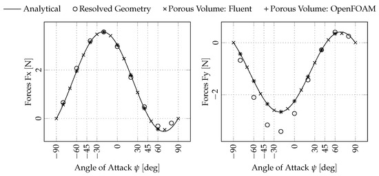
Figure 7.
Expanded Mesh: analytical, FVM porous vs. resolved geometry CFD solutions for Fx and Fy in the Case 1 flow.
In the case of expanded meshes, the resistance tensor also contains coefficient, as mentioned before. Given the results of LSE optimisation for the Case 1 flow, the condition for Case 2 flow is . Figure 8 compares under this condition. The resulting resistance tensor is the following:
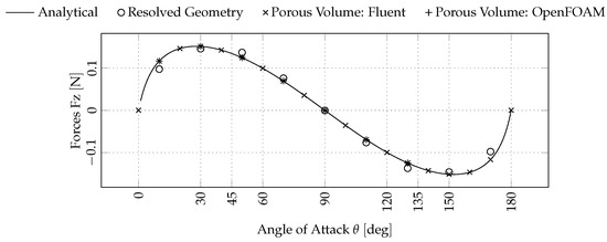
Figure 8.
Expanded mesh: analytical, FVM porous vs. resolved CFD solutions for Fz in the Case 2 flow.
As in the case with other permeable panels, the proposed framework managed to capture the macro-behaviour of the expanded mesh, especially in terms of . Additionally, the porous model manages to reproduce the sign reversal of the forces at extreme angles of attack. It can be seen that is an order of magnitude less compared to and . Therefore, the influence of coefficient is marginal in this case.
It is worth noting that across all the resolved geometry simulations, the pressure forces were several orders of magnitude higher than the viscous ones. This justified the initial assumptions taken while developing the proposed framework, at least, for the screen typologies and sizes considered in this study.
5. Conclusions
The analytical solution, derived in the present work, established a relation between Forchheimer stress tensor coefficients and the forces experienced by a portion of a permeable panel that is far from the edges, modelled as a porous medium. The least-squares optimisation provided a straightforward and flexible way to match porous model output with geometry resolved results. This is the essential first step in addressing the multi-scale modelling problem for permeable screens in the double skin facades or windbreaker contexts and reliably representing the screens’ macro behaviour in CFD simulations.
In the case of wired mesh panels and perforated panels, the porous model successfully replicated the macro behaviour across all inflow angles. It has been demonstrated that for these two typologies, the proper setup of the resistance coefficients in the tangential directions is essential to properly characterise even relatively thin screens. Moreover, it has been shown that the magnitude of the coefficients is highly correlated with the panel thickness. The current modelling practice of setting these values an order of magnitude higher with respect to the normal direction resistance coefficient results in entirely different flow from the one occurring in reality.
In cases of complex geometries such as air louvers and expanded meshes, it has been demonstrated that a volumetric porous media with a non-diagonal Forchheimer stress tensor can model the macro behaviour of permeable screens, as well. For these geometries, the tangential forces (or equivalently the flow deflection) were not as closely replicated as the normal force (or equivalently the pressure drop). Further investigation is required to establish the reason for this observation.
The method to evaluate resistance coefficients described in this study allows for an efficient search of a macro-flow solution, which is realisable within the porous modelling framework. Meanwhile, to fully assess the applicability of the porous modelling approach itself, it is necessary to quantify the uncertainty of the macro-behaviour of permeable screens in question. At the same time, adopting the proposed framework to characterise permeable panels in the double skin facade or windbreaker contexts requires a modification of the current experimental practice. Instead of solely measuring the pressure drop in wall-bounded flow conditions, a screen should be placed in an open section, and the forces in all principal directions should be measured under varying inflow angles of attack on a cutout portion of the screen sufficiently far from the edges.
The computational gains introduced by the adoption of porous medium models provide the possibility to carry out practical CFD simulations of large-scale civil engineering structures with permeable double skin facades or wind-screens. The work presented in this paper provides CFD modelers with clear guidelines on the implementation of porous models and furthers their understanding of possible model limitations.
- Future scope of work
In this work, only a volumetric porous medium was considered. This was mainly driven by the fact that most existing CFD software packages already include a capability to model such media using Darcy–Forchheimer formulations. It is, however, possible to define custom pressure jump baffles similar to the ones proposed by [18], characterised by 5 Forchheimer coefficients. The modelling capability of such baffles as well as computational gains and solution stability can be compared with respect to the modelling techniques considered thus far. In the derivation of the analytical solution, the viscous stresses have been neglected, which limits the applicability of the analytical solution to cases where this assumption holds. It is possible to seek an analytical solution without such simplification [32]. Another possibility is to use a black-box optimisation framework to search for the optimal coefficients that will minimise the difference between the porous model and geometry resolved simulation results. However, this may prove to be computationally demanding, due to the high number of model evaluations.
In terms of medium- and high-fidelity simulations, uncertainty quantification can be performed. Ideally, a series of targeted wind tunnel tests can provide high-confidence data sets describing the macro-behaviour of the facade panels. This can serve as a basis for further validation of the porous modelling approach against experimental studies.
Author Contributions
Conceptualization, Y.M.; methodology, Y.M., G.P., P.S. and A.Z.; software, Y.M., G.P. and P.S.; formal analysis, Y.M.; investigation, Y.M. and G.P.; writing—original draft preparation, Y.M.; writing—review and editing, Y.M., G.P. and P.S.; visualization, Y.M.; supervision, A.Z. All authors have read and agreed to the published version of the manuscript.
Funding
This research received no external funding.
Data Availability Statement
The raw data supporting the conclusions of this article will be made available by the authors on request.
Conflicts of Interest
The authors declare no conflicts of interest.
Nomenclature
The following nomenclature is used throughout this manuscript:
| u | Fluid velocity vector |
| U | Fluid velocity magnitude |
| p | Fluid pressure |
| Fluid density | |
| d | Darcy tensor |
| f | Forchheimer tensor |
| F | Total Force vector on a portion of the permeable screen (or porous volume) considered for the estimation of the Forchheimer tensor coefficients |
| Cartesian coordinate system axis, where x is aligned with the permeable screen normal and are aligned in the directions tangential to the screen plane | |
| Angles of attack of the incoming flow in the spherical coordinate system | |
| t | Thickness of the 3D porous volume region |
| Height and width of the portion of the permeable screen |
References
- Lago, A.; Trabucco, D.; Wood, A. Chapter 6—Architectural aspects and building system interaction. In Damping Technologies for Tall Buildings; Lago, A., Trabucco, D., Wood, A., Eds.; Butterworth-Heinemann: Oxford, UK, 2019; pp. 437–464. [Google Scholar] [CrossRef]
- Belloli, M.; Rosa, L.; Zasso, A. Wind loads and vortex shedding analysis on the effects of the porosity on a high slender tower. J. Wind. Eng. Ind. Aerodyn. 2014, 126, 75–86. [Google Scholar] [CrossRef]
- Lo, Y.L.; Wu, Y.T.; Fu, C.L.; Yu, Y.C. Wind load reduction effects on inner buildings by exterior porous façades. Build. Environ. 2020, 183, 107148. [Google Scholar] [CrossRef]
- Ricci, M.; Patruno, L.; Kalkman, I.; de Miranda, S.; Blocken, B. Towards LES as a design tool: Wind loads assessment on a high-rise building. J. Wind. Eng. Ind. Aerodyn. 2018, 180, 1–18. [Google Scholar] [CrossRef]
- Lamberti, G.; Gorlé, C. Sensitivity of LES predictions of wind loading on a high-rise building to the inflow boundary condition. J. Wind. Eng. Ind. Aerodyn. 2020, 206, 104370. [Google Scholar] [CrossRef]
- Montazeri, H.; Blocken, B.; Janssen, W.; van Hooff, T. CFD evaluation of new second-skin facade concept for wind comfort on building balconies: Case study for the Park Tower in Antwerp. Build. Environ. 2013, 68, 179–192. [Google Scholar] [CrossRef]
- Stasi, R.; Ruggiero, F.; Berardi, U. Influence of cross-ventilation cooling potential on thermal comfort in high-rise buildings in a hot and humid climate. Build. Environ. 2024, 248, 111096. [Google Scholar] [CrossRef]
- Pomaranzi, G.; Bistoni, O.; Schito, P.; Rosa, L.; Zasso, A. Wind Effects on a Permeable Double Skin Façade, the ENI Head Office Case Study. Fluids 2021, 6, 415. [Google Scholar] [CrossRef]
- Xu, M.; Patruno, L.; Lo, Y.L.; de Miranda, S.; Ubertini, F. On the numerical simulation of perforated bluff-bodies: A cfd study on a hollow porous 5: 1 rectangular cylinder. Wind. Struct. 2022, 34, 1–14. [Google Scholar]
- Xu, M.; Patruno, L.; Lo, Y.L.; de Miranda, S. On the use of the pressure jump approach for the simulation of separated external flows around porous structures: A forward facing step. J. Wind. Eng. Ind. Aerodyn. 2020, 207, 104377. [Google Scholar] [CrossRef]
- Pomaranzi, G.; Bistoni, O.; Schito, P.; Zasso, A. Numerical modelling of three-dimensional screens, treated as porous media. Wind. Struct. 2021, 33, 409–422. [Google Scholar] [CrossRef]
- Arghode, V.K.; Joshi, Y. Modeling Strategies for Air Flow through Perforated Tiles in a Data Center. IEEE Trans. Components Packag. Manuf. Technol. 2013, 3, 800–810. [Google Scholar] [CrossRef]
- Bourdin, P.; Wilson, J.D. Windbreak Aerodynamics: Is Computational Fluid Dynamics Reliable? Bound.-Layer Meteorol. 2007, 126, 181–208. [Google Scholar] [CrossRef]
- Santiago, J.; Martín, F.; Cuerva, A.; Bezdenejnykh, N.; Sanz-Andrés, A. Experimental and numerical study of wind flow behind windbreaks. Atmos. Environ. 2007, 41, 6406–6420. [Google Scholar] [CrossRef]
- Tominaga, Y.; Shirzadi, M. RANS CFD modeling of the flow around a thin windbreak fence with various porosities: Validation using wind tunnel measurements. J. Wind. Eng. Ind. Aerodyn. 2022, 230, 105176. [Google Scholar] [CrossRef]
- Xu, M.; Patruno, L.; Lo, Y.L.; de Miranda, S. Simulation strategies for wind shields and porous barriers for bridge deck optimization. Structures 2022, 40, 824–839. [Google Scholar] [CrossRef]
- Teitel, M.; Dvorkin, D.; Haim, Y.; Tanny, J.; Seginer, I. Comparison of measured and simulated flow through screens: Effects of screen inclination and porosity. Biosyst. Eng. 2009, 104, 404–416. [Google Scholar] [CrossRef]
- Xu, M.; Patruno, L.; de Miranda, S. A pressure–velocity jump approach for the CFD modelling of permeable surfaces. J. Wind. Eng. Ind. Aerodyn. 2023, 233, 105317. [Google Scholar] [CrossRef]
- Xu, M.; Patruno, L.; de Miranda, S. Simulation of permeable surfaces using the pressure–velocity jump approach: A lamellar screen upstream of a ground-mounted obstacle. J. Wind. Eng. Ind. Aerodyn. 2024, 250, 105756. [Google Scholar] [CrossRef]
- Packwood, A. Flow through porous fences in thick boundary layers: Comparisons between laboratory and numerical experiments. J. Wind. Eng. Ind. Aerodyn. 2000, 88, 75–90. [Google Scholar] [CrossRef]
- Oezcan, M. How to Use the Porous Media Feature to Define a Perforated Plate? In SimScale Documentation. 2020. Available online: https://www.simscale.com/knowledge-base/how-to-use-porous-media-feature-to-define-perforated-plate/ (accessed on 18 June 2024).
- Qiao, D.; Mackay, E.; Yan, J.; Feng, C.; Li, B.; Feichtner, A.; Ning, D.; Johanning, L. Numerical simulation with a macroscopic CFD method and experimental analysis of wave interaction with fixed porous cylinder structures. Mar. Struct. 2021, 80, 103096. [Google Scholar] [CrossRef]
- Feichtner, A.; Mackay, E.; Tabor, G.; Thies, P.R.; Johanning, L. Comparison of Macro-Scale Porosity Implementations for CFD Modelling of Wave Interaction with Thin Porous Structures. J. Mar. Sci. Eng. 2021, 9, 150. [Google Scholar] [CrossRef]
- Safer, N.; Woloszyn, M.; Roux, J.J. Three-dimensional simulation with a CFD tool of the airflow phenomena in single floor double-skin facade equipped with a venetian blind. Sol. Energy 2005, 79, 193–203. [Google Scholar] [CrossRef]
- Ooi, C.; Chiu, P.H.; Raghavan, V.; Wan, S.; Poh, H.J. Porous media representation of louvers in building simulations for natural ventilation. J. Build. Perform. Simul. 2019, 12, 494–503. [Google Scholar] [CrossRef]
- Patursson, Ø.; Swift, M.R.; Tsukrov, I.; Simonsen, K.; Baldwin, K.; Fredriksson, D.W.; Celikkol, B. Development of a porous media model with application to flow through and around a net panel. Ocean. Eng. 2010, 37, 314–324. [Google Scholar] [CrossRef]
- Zhao, Y.P.; Bi, C.W.; Dong, G.H.; Gui, F.K.; Cui, Y.; Guan, C.T.; Xu, T.J. Numerical simulation of the flow around fishing plane nets using the porous media model. Ocean. Eng. 2013, 62, 25–37. [Google Scholar] [CrossRef]
- Zhao, Y.P.; Bi, C.W.; Liu, Y.X.; Dong, G.H.; Gui, F.K. Numerical Simulation of Interaction between Waves and Net Panel Using Porous Media Model. Eng. Appl. Comput. Fluid Mech. 2014, 8, 116–126. [Google Scholar] [CrossRef]
- Chen, H.; Christensen, E.D. Investigations on the porous resistance coefficients for fishing net structures. J. Fluids Struct. 2016, 65, 76–107. [Google Scholar] [CrossRef]
- Marykovskiy, Y. Forchheimer Coefficients Calculator for Permeable Screens and Air Louvers; Zendodo: Geneva, Switzerland, 2024. [Google Scholar] [CrossRef]
- Buscemi, L. A CFD’s Modeling of a Screen Considering as a Porous Media. Master’s Thesis, Politecnico di Milano, Milan, Italy, 2019. [Google Scholar]
- Knupp, P.M.; Lage, J.L. Generalization of the Forchheimer-extended Darcy flow model to the tensor premeability case via a variational principle. J. Fluid Mech. 1995, 299, 97–104. [Google Scholar] [CrossRef]


Disclaimer/Publisher’s Note: The statements, opinions and data contained in all publications are solely those of the individual author(s) and contributor(s) and not of MDPI and/or the editor(s). MDPI and/or the editor(s) disclaim responsibility for any injury to people or property resulting from any ideas, methods, instructions or products referred to in the content. |
© 2024 by the authors. Licensee MDPI, Basel, Switzerland. This article is an open access article distributed under the terms and conditions of the Creative Commons Attribution (CC BY) license (https://creativecommons.org/licenses/by/4.0/).