Article

Flow and Aeroacoustic Characteristics of Underexpanded Supersonic Jets Exhausting from a Conical Converging Nozzle

by
Konstantin Volkov
Department of Mechanical Engineering, Kingston University, London SW15 3DW, UK
Fluids 2024, 9(7), 148; https://doi.org/10.3390/fluids9070148
Submission received: 27 March 2024 / Revised: 13 June 2024 / Accepted: 20 June 2024 / Published: 22 June 2024
(This article belongs to the Special Issue High Speed Flows, 2nd Edition)

Abstract

:
Ensuring the safety of space flights and solving the problems of reducing acoustic loads during the launch of space vehicles requires not only the development of new technical systems for launch complexes, but also methods for the numerical simulation of fluid and aeroacoustic fields generated by supersonic jets. The growing regulations for space vehicle noise also explain the interest in developing models and techniques that anticipate flow and the aeroacoustic characteristics of supersonic jets. Together with integral techniques for computing far-field noise, development of relevant mathematical models and implementation of numerical tools, the concepts of computational fluid dynamics (CFD) and computational aeroacoustics (CAA) are covered. The noise generated by a supersonic underexpanded jet is used to illustrate the capabilities of current numerical modelling and simulation tools. The jet structure, flow properties, and aeroacoustic quantities are affected by the nozzle pressure ratio. The outcomes of numerical simulation are contrasted with existing experimental and computational data. The available numerical modelling and simulation tools facilitate the development of novel computational methods and methodologies for challenges in CFD and CAA, in addition to solving research and engineering problems.

1. Introduction

One of the primary issues with manned flight and space flight safety is minimizing the acoustic influence on a rocket and space launch vehicle. Space exploration tasks require an increase in the power of the rocket launcher. An increase in the power of space launch vehicles leads to an increase in aerodynamic noise, which plays a key role on the launch pad [1].
When launching a space vehicle, the gas jets of the propulsion system, interacting with each other and with the structural elements of the launch facility, lead to the formation of powerful acoustic fields, as a result of which the space vehicle experiences strong vibro-acoustic stresses. Acoustic protection solutions, such as insulating materials, can be used to reduce vibro-acoustic stresses. This approach, however, is not the best one because it increases the mass of the head compartment that houses the astronauts. Combining two approaches by using local acoustic protection in the head compartment region and lowering the noise generated by supersonic jets of operational propulsion systems is a way to solve this issue [2].
A supersonic non-isobaric and non-isothermal jet is a complex source of noise. To ensure the safety of space flights, it is necessary not only to emit jet streams and the acoustic fields generated by them, but also to consider possible ways to suppress acoustic fields in the area of an operating propulsion system [3].
The governing parameter of an underexpanded turbulent jet is the nozzle pressure ratio (NPR), defined as NPR = p 0 / p , where p 0 and p are the total pressure at nozzle inlet and the atmospheric pressure [4].
A supersonic turbulent jet is a complex source of acoustic radiation [5]. To assess the noise of a jet, semi-empirical dependencies are widely used, in which the sound power is expressed through the jet speed, diameter of the nozzle, density of the gas jet, and environment using empirical constants. Models of broadband noise sources give an idea of the integral value of the sound level and the spatial distributions of noise sources. When supersonic nozzle jets are produced at high-enough exhaust velocities, their total sound power is proportional to the third power of speed rather than the eighth power, as is the case in subsonic jets. In addition to their relatively low accuracy, semi-empirical approaches do not allow one to evaluate the effects of measures to reduce jet noise. In acoustic experiments, acoustic fields are studied, but detailed information about distributions of flow quantities, as a rule, is absent. To accurately reproduce jet acoustic fields, the ability to simulate the entire flow field is essential [6].
Methods for calculating noise are divided into two groups: direct methods and integral methods. Using governing equations, direct techniques (Direct Noise Computation, DNC) compute both the sound wave propagation from the turbulent region to the observer position and sound generation caused by turbulent structures. Detailed meshes and expanded computational domains are necessary for direct modelling. The integral techniques are based on the independent computation of noise generation and its propagation. The first step involves solving the governing equations and storing data on specific control surfaces. In the second step, integral formulas are utilized to compute the sound propagation to the observer position based on data recorded on control surfaces. Acoustic properties are calculated at great distances from the source of noise thanks to integral approaches. Ffowcs Williams–Hawkings equation (FW–H) and Kirchhoff method are the two most well-known integral approaches. FW–H equation accounts for non-linear factors, which permits the integration surface to be placed in areas with greater noise levels where the linear acoustics approximation is broken. This is the primary distinction between FW–H approach and Kirchhoff method. Numerous studies include the findings from experimental and numerical examinations of supersonic jets and the noise they produce [3,7,8].
The following noise components are widely acknowledged: radiation from turbulent vortices convecting at supersonic speed in relation to the surroundings; the broadband component of shock noise produced by turbulence interacting with shock waves; and the discrete component resulting from jet instability under specific flow regimes. The nozzle pressure ratio and Mach number have an impact on overall noise level of supersonic jets. The analysis of experimental data is made more difficult by the various effects that these parameters have on the noise of various components.
An experimental and numerical study of the initial section of a supersonic underexpanded jet flowing from a convergent axisymmetric nozzle and a nozzle with chevrons is performed in [9]. The length of the jet’s initial section grows as the Mach number increases because as the mixing intensity reduces, the jet mixing layers’ thickness decreases, and so on. Relations that restrict the rise of turbulent viscosity and turbulence energy close to shock waves are utilized to enhance the accuracy of description of turbulent flows in the presence of shock waves [10,11]. Creating approximations for the terms in the transport equation of turbulent kinetic energy [12,13] that account for the effect of compressibility on turbulence and altering the model constants [14,15] are the two most popular methods of modifying a turbulence model.
The study [15] presents a semi-empirical model for noise calculation that is simplified. Turbulent mixing produces noise from two distinct sources: small-scale structures that are dominating near the jet boundary and noise produced by Mach waves, which are large-scale structures that propagate downstream. Two different models are used because both large- and small-scale structures produce the broadband spectrum. The semi-empirical model [15] has stable accuracy over a wide frequency range for cold- and moderate-temperature jets. For hot jets, the model proposed in [16] is used, which, in addition to typical sources of cold jets (such as Reynolds turbulent stress covariance), takes into account temperature fluctuations as a separate noise source. The studies [17,18] explore the flow and acoustic fields of jets flowing from conical nozzles, and the study [19] discusses self-oscillating processes in supersonic jets.
Numerous studies have examined acoustic quantities of a supersonic jet and impact of injecting water in mixing layer on intensity of acoustic radiation. Studies [20,21] conducted a number of experimental investigations on impact of injecting water into a solid propellant rocket engine supersonic jet. The results obtained show that, starting from a certain value of water supply pressure, the relative flow rate has insignificant effect on amount of noise reduction. In this case, injection is most effective in close proximity to the nozzle outlet at a certain angle [22,23].
Optimizing the computational technologies used is essential to using aeroacoustics techniques successfully, which eliminates or reduces needless costs related to computer resources. The computer modelling of fluid flows and acoustic properties of supersonic jets entering a flooded region from a conical converging nozzle is the focus of this study. The noise modal composition is examined, and it is established how the characteristics of the resulting noise directionality relate to its different constituents and sources. The jet noise level in the far field is predicted, and the outcomes of numerical simulations are compared with computational and experimental data that are currently available for different input parameters.

2. Structure of Supersonic Jet

The nozzle diameter, d a , and the nozzle half-opening angle, θ a , are the geometric parameters impacting on jet structure and quantities exhausted from a conical nozzle. In the general case, dimensionless regime parameters that determine the flow in a jet are the Mach number of the jet, M a , the ratio of specific heat capacities at constant pressure and constant volume, γ , the ratio of stagnation temperatures of the jet and surroundings, T 0 / T , and the ratio of static pressures at the nozzle outlet and surroundings n = p a / p (degree of non-design). Three outflow regimes for a supersonic jet are seen based on degree of non-design: (i) an overexpanded jet if n < 1 , (ii) a design jet if n = 1 , and (iii) an underexpanded jet if n > 1 . Three zones are typically identified in jet flow analysis: initial (gas-dynamic), transition, and main. Off-design (n ≠ 1) supersonic jets in the initial zone are best suited for the implementation of self-oscillatory processes due to unevenness of parameters over the jet cross section [19].
Figure 1 depicts the structure of the gas-dynamic section of a jet outflow from a conical nozzle (1). The barrel-shaped structure in the early area faces the surroundings in a convex manner. The mixing layer (2), center shock wave (3) (Mach disk), barrel (4), reflected shock waves (5), and expansion fans (6) are the key components of the jet in this region. The position of the Mach disk in the free supersonic jet, l c , and length of the first barrel, l s , are also depicted in the image. Typical for the degree of non-design n > 1 is a jet diamond shock wave structure. In the gas-dynamic zone, many barrels of jet can exist for n < 2 ; dangling shocks are reflected regularly off the jet centerline without a Mach disk forming.

3. Sources of Jet Noise

The noise emissions of supersonic jets occur due to interaction of shock waves and turbulence resulting in noise in the range of relatively low frequencies.

3.1. Mixing Noise

Mixing noise occurs due to turbulent mixing of supersonic jet with surrounding. Large transverse velocity gradients that cause instability and a rise in harmonic amplitudes are characteristics of shear layers. Wave attenuation results from a decrease in the velocity gradient and an increase in the thickness of shear layers downstream. A wideband wavenumber spectrum is produced by varying wave amplitudes. Sound is produced by harmonics with a supersonic phase velocity relative to surrounding that are feasible in the short-wave portion of spectrum. Acoustic radiation from small-scale turbulence and acoustic radiation from large-scale turbulent eddies make up this noise [15]. While small-scale eddies produce background noise, large-scale vortices are the dominating generators. Turbulent noise dominates in a narrow interval of Strouhal numbers, 0.1 < St < 0.25 [24].
In the case when the speed of vortex transfer (convective speed) exceeds the speed of sound in the surroundings, Mach waves are emitted, the theory of which is developed in [25,26]. Large coherent turbulent structures simulate sine waves of instability with a wavelength equal to the distance between two successive eddies. They move with convective speed v c . In the surroundings, the speed of sound remains constant and equals c 0 . If v c > c 0 , Mach waves are emitted at an angle θ = arccos ( c 0 / v c ) . The peak of the Strouhal number, with which Mach waves are emitted, corresponds to the strongest instability wave [27]. The impact of non-isothermal flow on the emission of Mach waves is discussed in [28].

3.2. Broadband Shock Wave Noise

Broadband shock wave noise occurs due to the interaction of turbulent vortical structures propagating downstream and the diamond shock wave structure of a supersonic jet. A description of this noise source and relationships for the intensity of acoustic radiation are given in [29]. The intensity of the acoustic disturbance is found as I M a 2 1 2 , where M a is the nozzle outlet Mach number.
The relationship between flow velocity, jet temperature, and the angle of maximum radiation into the far field is measured is positive. For a cold jet ( M a 1.4 , T 0 300 K), the angle of maximum radiation is around 25 degrees, and for a high-temperature jet ( M a 3.4 , T 0 2900 K), it is around 65 degrees. The broadband noise produced by shock waves lacks a noticeable directionality, and the maximal acoustic radiation of mixing noise corresponds to an angle range from 30 to 60 degrees [3]. The intensity of the shock waves in the jet determines the noise intensity, which is slightly influenced by stagnation temperature [30]. The amount of mixing noise rises as stagnation temperature rises. At large angles, the sound produced by shock waves is more noticeable for cold jets, where mixing noise is small [3].

3.3. Discrete Tone

The noise radiation of supersonic jets is related shock waves and characterized by the presence in the noise spectrum of a discrete component (screech). Its frequency and intensity depends on the Mach number, nozzle pressure ratio and temperature ratio, the presence of co-flow, and other factors [31,32]. The level of the discrete component significantly exceeds the level of broadband components. It is caused by acoustic feedback [3] and determines the total level of noise emitted by a supersonic jet.
Disturbances occur as a result of the development of Kelvin–Helmholtz instability in the jet boundary. They propagate downstream with a convective velocity v c . These vortices reach the shock wave at the end of the first jet barrel, which has a length of l s , and generate an acoustic wave that propagates to nozzle outlet and enhances the initial disturbances of jet boundary. The emission of a discrete tone depends on the length of the jet barrel, l s , the speed of sound in the surroundings, c 0 , and the convective speed of large coherent structures, v c . Many experimental studies show that the discrete component of the noise spectrum depends on outlet Mach number, and it is realized in a certain interval of nozzle-to-pressure ratios. Increasing co-flow velocity leads to a monotone decrease in the frequency of the discrete component.

4. Jet Flow Field

Several acoustic models are utilized in engineering practice, which allows for a significant reduction in the amount of processing power needed to achieve the desired outcome. This method does not always produce accurate findings, particularly when it comes to accounting for the contribution of different physical factors to acoustics, like wave scattering, diffraction, reflection from solid surfaces, and others. Both direct methods (where all acoustic oscillation scales in the computational domain are resolved) and acoustic analogy approaches (where the near-field acoustic oscillation scales are identified, followed by modelling and far-field parameter calculation) are used to calculate acoustic parameters. The zone where acoustic waves propagate and the turbulent flow occurs are separated using a hybrid technique.
The equation describing unsteady three-dimensional viscous compressible flow in Cartesian coordinates ( x , y , z ) is written as
Q t + F x x + F y y + F z z = 0 .
The perfect gas equation of state is added to Equation (1). It has the form
p = ( γ 1 ) ρ e 1 2 v x 2 + v y 2 + v z 2 .
The vector of conservative variables Q and the flux vectors F x , F y , F z have the form
Q = ρ ρ v x ρ v y ρ v z ρ e ,
F x = ρ v x ρ v x v x + p τ x x ρ v x v y τ x y ρ v x v z τ x z ( ρ e + p ) v x v x τ x x v y τ x y v z τ x z + q x ,
F y = ρ v y ρ v y v x τ y x ρ v y v y + p τ y y ρ v y v z τ y z ( ρ e + p ) v y v x τ y x v y τ y y v z τ y z + q y ,
F z = ρ v z ρ v z v x τ z x ρ v z v y τ z y ρ v z v z + p τ z z ( ρ e + p ) v z v x τ z x v y τ z y v z τ z z + q z .
The components of heat flux and viscous stress tensor are
τ i j = μ v i x j + v j x i 2 3 v k x k δ i j , q i = λ T x i .
Here, t is time, ρ is the density, v x , v y , v z are the velocity components in x, y and z directions, p is the pressure, e is the total energy per unit mass, T is the temperature, γ is the ratio of specific heat capacities.
Air standard assumptions (air is treated as an ideal gas at normal atmospheric conditions) are applied to simulate the air flow field. The impact of the temperature of air on the structure of the supersonic jet is not a part of the present study.
The molecular viscosity, μ , is a function of temperature. For air, it is modelled with Sutherland’s law
μ μ * = T T * 3 / 2 T * + S 0 T + S 0 ,
where μ * and T * are a reference viscosity and reference temperature, S 0 is an experimental constant. So, μ * = 1.7894 × 10 5 kg/(m s), T * = 273.11 K, and S 0 = 110.56 K for air. The thermal conductivity, λ , is linked to specific heat capacity at constant pressure, c p , and Prandtl number, Pr, so that λ = c p μ / Pr , and Pr = 0.7 for air.
The development of vortical structures, as well as their propagation and interaction with a wall, must be understood when modelling the unsteady turbulent flows and acoustic fields they produce [33]. Eddy-resolving approaches, like large-eddy simulation (LES), hybrid URANS/LES methods, and detached eddy simulation (DES) and its modifications are some of the most popular approaches used in modelling of turbulent flows. When compared to direct numerical simulations (DNS), LES requires less computer resources, since it simulates the interaction of large eddies with small-scale turbulence using subgrid models [34]. The scope of usage of LES in DES and its variations are automatically selected by the typical grid size and the existence of turbulent flow components.
The numerical dissipation of finite-difference schemes in ILES (Implicit LES) plays the role of subgrid viscosity. This is because it is critical to accurately characterize the change from laminar to turbulent flow regimes in the mixing layers descending from the nozzle edge when computing the noise of turbulent jets within the context of LES. The range of noise frequencies that LES can resolve is determined by this process, which happens quickly at high Reynolds numbers. It is impossible to resolve small-scale vortex formations that originate from the boundary layer on the nozzle wall and cause the mixing layer to experience turbulence because of the high computer resource requirements. The application of traditional (explicit) subgrid viscosity models typically causes the transition process to lag. A potential solution to this problem is to substitute the fake turbulent pulsations for the real ones near the nozzle outlet. This method adds spurious noise, though, which is hard to separate from the real noise.

5. Jet Acoustic Field

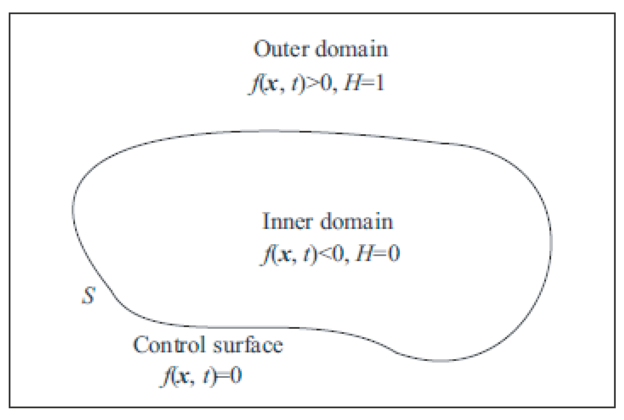
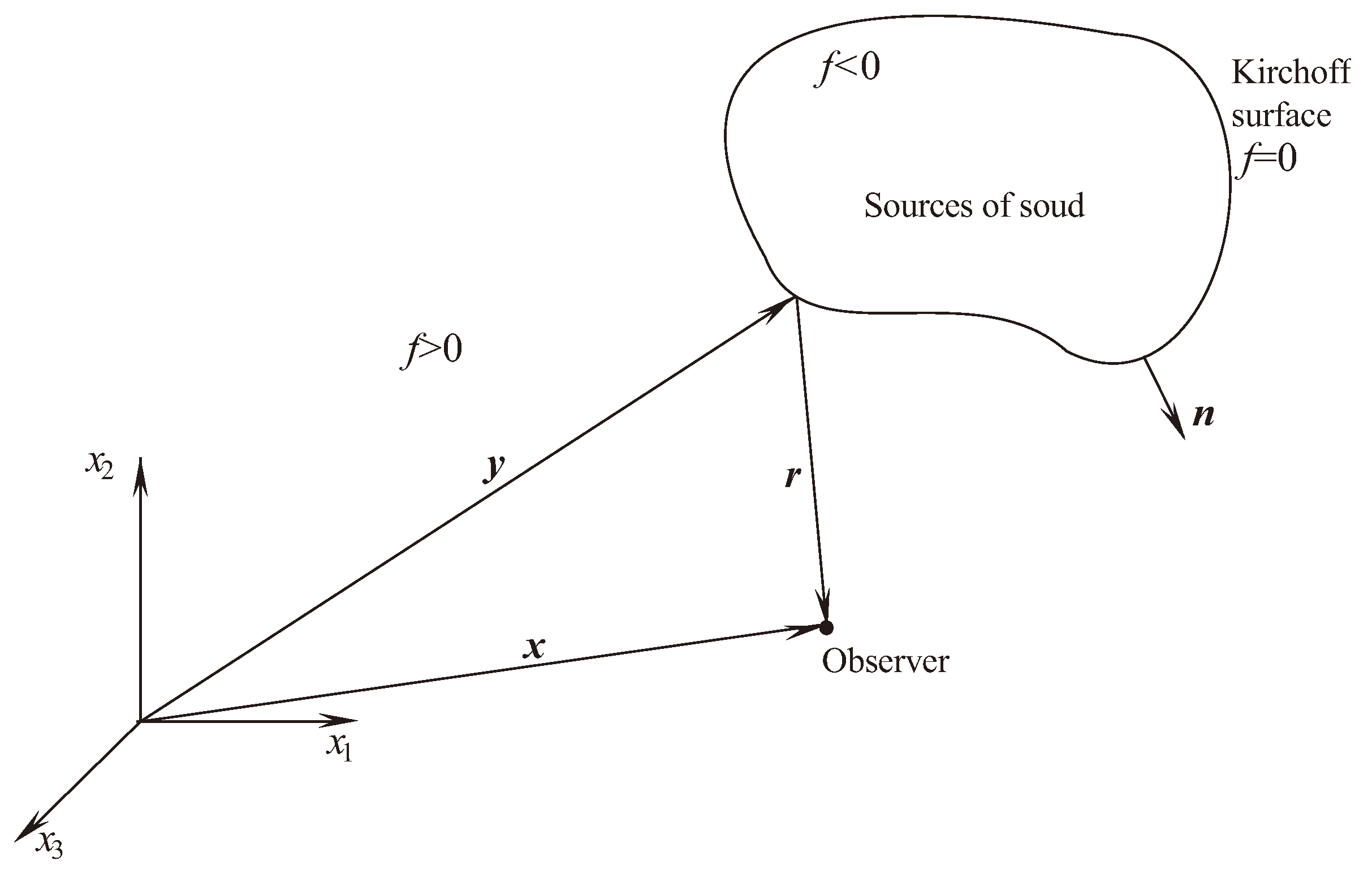
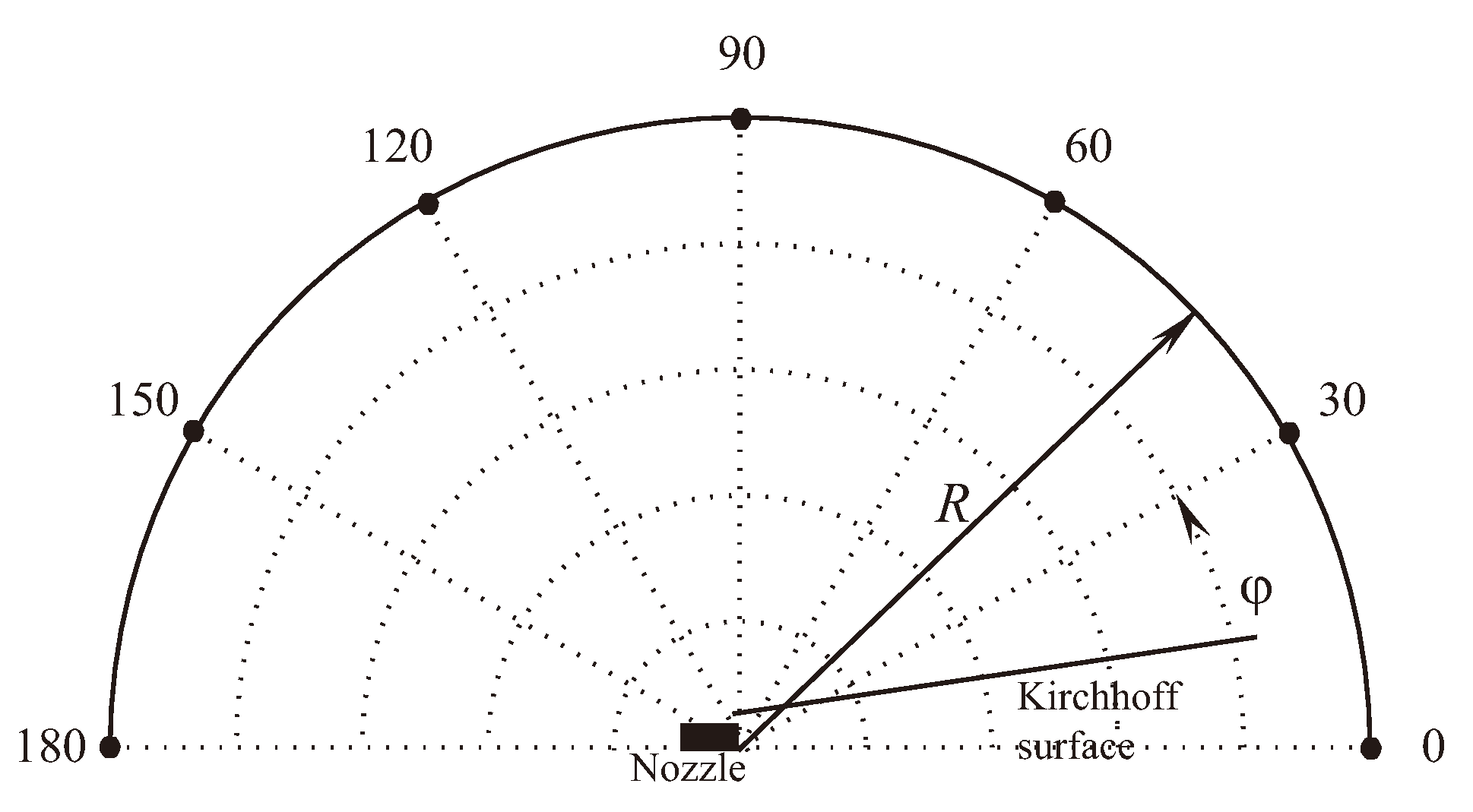
The flow of compressible viscous air in an unbounded region with solid boundaries is considered. An inhomogeneous wave equation is created by transforming the Navier–Stokes equations in methods based on the Lighthill acoustic analogy. A control surface (Figure 2) is introduced, encompassing all solid entities in the computational domain at each time moment, to derive the Lighthill wave equation characterizing the sound field. The function-indicator f is defined, where f > 0 is the outside surface, f < 0 is the inside surface, and f = 0 on the Kirchhoff surface surrounding the noise sources.
The control surface f ( x , t ) = 0 (Kirchhoff surface) separates the internal and external flow regions. The control surface is defined with the marking function
f ( x , t ) = > 0 , if x > S , = 0 , if x S , < 0 , if x < S .
The flow quantities (density, momentum, pressure) are found in a way to correctly include the discontinuity through the interface using the Heaviside function
H [ f ( x , t ) ] = 1 , if f ( x , t ) > 0 , 0 , if f ( x , t ) < 0 .
When deriving the FW–H equation, the following differentiation rule is applied
d H d t = f t + f x i x i t H f = H t + v i H x i = 0 .
Derivatives are expressed as
H t = v i H x i = v i δ ( f ) f x i ; H x i = H f f x i = δ ( f ) f n i .
Here, v i = x i / t is the component of the speed of control surface, and n i is the component of the local outer normal to control surface. It is found as
n i = f x i f x j f x j 1 / 2 .
The Dirac delta function is
δ [ f ( x , t ) ] = H f = 1 , if f ( x , t ) = 0 , 0 , if f ( x , t ) 0 .
The FW–H equation outside the Kirchhoff surface, covering sources of sound radiation (there are no barriers between the source and the observer), is written in the form
ρ ˜ H ( f ) = 2 x i x j V ( τ ) [ T i j ] 4 π c 0 2 y x d 3 y x i S ( τ ) ρ u i ( u j v j ) + p ˜ δ i j τ i j 4 π c 0 2 y x d S j ( y ) + t S ( τ ) ρ ( u j v j ) + ρ 0 v j 4 π c 0 2 y x d S j ( y ) .
Square brackets mean that the functions are taken accounting for the delay of the signal τ = t y x / c 0 coming from the source to the observation point (retired time). The radius vector is r = y x ; it refers to distance between the observation point and the point on the Kirchhoff surface (Figure 3). The components of the Lighthill stress tensor have the form
T i j = ( p p 0 ) c 0 2 ( ρ ρ 0 ) δ i j + ρ u i u j τ i j .
Here, ρ is density, p is pressure, c is the speed of sound, u i and v i are the components of flow velocity and the velocity of the control surface, and τ i j are the components of the viscous stress tensor. Index 0 refers to flow quantities in surrounding.
The partial derivatives / x i are converted in partial derivatives / t . Quadrupole noise sources are disregarded, presuming that the control surface is sufficiently large to cover volumetric sources, to derive the wave Equation (2), which is convenient for numerical calculations. Farassat’s formulation I [35] is the integral form of the FW–H equation. It is written for acoustic pressure p ˜ ( x , t ) = p ( x , t ) p 0 and has the form
H p ˜ ( x , t ) = H p ˜ T ( x , t ) + H p ˜ L ( x , t ) .
Here,
4 π p ˜ T ( x , t ) = t f ( y , τ ) = 0 ρ 0 U n r 1 M r r e t d S ( y ) ; 4 π p ˜ L ( x , t ) = 1 c 0 t f ( y , τ ) = 0 L r r 1 M r r e t d S ( y ) + f ( y , τ ) = 0 L r r 2 1 M r r e t d S ( y ) .
Time derivatives shift under the integral sign when modelling flows with a dynamic control surface because they lead to numerical instabilities. The FW–H equation is expressed in the integral form written for acoustic pressure p ˜ ( x , t ) = p ( x , t ) p 0 . Farassat’s formulation II [36] has the form
H p ˜ ( x , t ) = H p ˜ T ( x , t ) + H p ˜ L ( x , t ) + H p ˜ Q ( x , t ) ,
where
4 π p ˜ T ( x , t ) = f ( y , τ ) = 0 ρ 0 U ˙ n + U n ˙ r 1 M r 2 r e t d S ( y ) + f ( y , τ ) = 0 ρ 0 U n r M ˙ r + c 0 M r M 2 r 2 1 M r 3 r e t d S ( y ) ; 4 π p ˜ L ( x , t ) = 1 c 0 f ( y , τ ) = 0 L ˙ r r 1 M r 2 r e t d S ( y ) + f ( y , τ ) = 0 L r L M r 2 1 M r 2 r e t d S ( y ) + 1 c 0 f ( y , τ ) = 0 L r r M ˙ r + c 0 M r M 2 r 2 1 M r 3 r e t d S ( y ) ; 4 π p ˜ Q ( x , t ) = 1 c 0 2 2 t 2 f ( y , τ ) > 0 Q r r r 1 M r r e t d V ( y ) + 1 c 0 t f ( y , τ ) > 0 3 Q r r Q i i r 2 1 M r r e t d V ( y ) + f ( y , τ ) > 0 3 Q r r Q i i r 3 1 M r r e t d V ( y ) .
Here, n i is the component of the outer normal to control surface in i direction, and r i = x i y i is the component of radius vector from a point on the Kirchhoff surface to the observation point. The dot denotes differentiation with respect to time. The multiplier D = 1 M r takes into account the Doppler effect. The function U i (modified speed) and its derivatives are found from
U i = ρ u i ρ 0 + 1 ρ ρ 0 v i , U n = U i n i , U ˙ n = v i n τ , U n ˙ = v i n i τ .
The relations yield the projection of a non-dimensional velocity vector (Mach number) on direction of the observer at the time of sound emission and its derivatives
M r = v i r i c 0 , M ˙ r = M ˙ i r i r , M ˙ i = 1 c 0 v i τ , M 2 = v i v i c 0 2 .
The components of the vector L and its derivatives are found as
L i = p p 0 δ i j + ρ u i u j v j n j τ i j , L r = L i r i r L ˙ r = L i τ r i r , L M = L i v i c 0 .
The components of the tensor Q are found as
Q i j = f > 0 T i j d n , Q r r = Q i j r i r j .
The delay of the signal from the source to observation point is taken into consideration by the functions. The statement τ = t r / c 0 is written at the moment of sound emission by elementary source (retired time), as indicated by index ret. Regarding the variable y , integration in the relation (4) is carried out in coordinate system connected to the source.
For a stationary control surface the following relations are valid:
Farassat’s formulation I
4 π p ˜ T ( x , t ) = t f ( y , τ ) = 0 ρ 0 U n r ret d S ( y ) ; 4 π p ˜ L ( x , t ) = 1 c 0 t f ( y , τ ) = 0 L r r ret d S ( y ) + f ( y , τ ) = 0 L r r 2 ret d S ( y ) ;
Farassat’s formulation II
4 π p ˜ T ( x , t ) = f ( y , τ ) = 0 ρ 0 U ˙ n r ret d S ( y ) ; 4 π p ˜ L ( x , t ) = 1 c 0 f ( y , τ ) = 0 L ˙ r r ret d S ( y ) + f ( y , τ ) = 0 L r r 2 ret d S ( y ) .
The terms in the right hand side of Equation (4) take on the following meaning when the control surface coincides with the surface of a solid body [37]. The term p ˜ L ( x , t ) is produced by a force acting on the fluid from the surface (loading contribution term). The term p ˜ Q ( x , t ) is determined by volumetric sound sources outside the control surface. The term p ˜ T ( x , t ) is determined by the shape and kinematics of movement of the control surface (thickness contribution term). It is difficult to calculate the term p ˜ Q ( x , t ) , since it necessitates integration over volume.
It is possible to solve the FW–H equation in real space. On a control surface, information on unsteady flow quantities is recorded. The output data contain the acoustic pressure time-dependence. Of interest are noise spectrum properties. After applying a Fourier transformation in time to the received sound signals, the frequency spectra of the signals are obtained based on the amplitude versus frequency, allowing for the determination of the sound pressure levels at certain observation points. The sound pressure level (SPL) and overall sound pressure level (OSPL) are
SPL = 20 log P i 2 1 / 2 P * , OSPL = 10 log i = 1 N 10 SPL i / 10 ,
where P i is the harmonic amplitude i, P * is the reference threshold ( P * = 2 × 10 5 Pa).

6. Numerical Method

The governing equations are solved with in-house finite volume code ran on unstructured meshes consisting of cells of various topologies. To achieve flexibility, the CFD solver treats all cells through an unstructured, edge-based data structure [38]. The fluxes though the surface of a cell are thus calculated on the basis of flow variables at nodes at either end of an edge, and an area associated with that edge (edge weight). The edge weights are pre-computed and take into account the geometry of the cell. The penalty for using an unstructured approach is that the connectivity information for each node, defining its neighbours, must be held in memory and used to access information indirectly, whereas a structured solver makes use of the inherent patterns in the mesh to derive neighbour information at each node.

6.1. CFD Solver

The density-based CFD solver works in an explicit time-marching technique, based on a three-step Runge–Kutta stepping procedure. Convergence to a steady state is accelerated by the use of multigrid techniques, and by the application of block-Jacobi preconditioning for high-speed flows, together with a separate low Mach number preconditioning method for use with low-speed flows. The sequence of meshes is created using an edge-collapsing algorithm. Preconditioning improves the rate at which information propagates through the flow domain during the solution iterations.
The governing equation is written in the form
d Q i n d t + L ( Q i n ) = 0 ,
where L ( Q i n ) is the spatial differential operator. The subscript i refers to the control volume, and the superscript n refers to the time layer. The flow variables vector averaged over the control volume V i is
Q i = 1 V i V i Q d V .
The flow residual within each cell of unstructured mesh is given by the sum of the normal inviscid and viscous fluxes over all faces
R i ( Q ) = 1 V i j N i F i j ( Q ) S i j ,
where F i j is the numerical flux from cell i through the face j at the face center, V i is the volume of cell i, S i j is the area of the face j of the cell i, and N i is the number of faces of the cell i.
The third-order Runge–Kutta method is applied to time discretization
Q i ( 1 ) = Q i ( 0 ) + Δ t L ( Q i ( n ) ) , Q i ( 2 ) = 3 4 Q i ( 0 ) + 1 4 Q i ( 1 ) + Δ t L ( Q i ( 1 ) ) , Q i ( 3 ) = 1 3 Q i ( 0 ) + 2 3 Q i ( 2 ) + Δ t L ( Q i ( 2 ) ) .
The stability region is a circle with radius r c = 1.25 .
The inviscid flux is calculated using gradient reconstruction of primitive variables. The calculations of gradients are based on the Green–Gauss theorem. The inviscid flux is found from the relation
F ( Q L , Q R ) = 1 2 F ( Q L ) + F ( Q R ) | A | Q R Q L .
where the subscripts L and R refer to cells on the left and on the right edges of the control volume. The matrix A is presented in the form A = R Λ L , where Λ is the diagonal matrix composed from the Jacobian eigenvalues, and R and L are the matrices composed from its right and left eigenvectors, respectively.
Viscous fluxes are discretized with a centered scheme of the second order, whereas inviscid fluxes are discretized with the MUSCL scheme (it is a combination of centered finite differences of the second order and a dissipative term, which are switched between by a flux limiter designed with characteristic variables). It satisfies the TVD (Total Variation Diminishing) condition and allows one to increase the order of approximation in spatial variables without losing monotonicity of the solution. The system of finite-difference equations is solved with the geometric multigrid method [38].
The numerical scheme assumes a piecewise parabolic distribution of the desired variables within the control volume [39]. At an intermediate step, auxiliary variables are defined
α 1 , m + 1 / 2 i = l m + 1 / 2 i Q m Q m 1 , α 2 , m + 1 / 2 i = l m + 1 / 2 i Q m + 1 Q m , α 3 , m + 1 / 2 i = l m + 1 / 2 i Q m + 2 Q m + 1 .
Here, l = { l 1 , l 2 , } represents the set of left eigenvectors. The superscript i corresponds to the ith eigenvalue and the ith eigenvector. Subscripts 1, 2, 3 are used for numbering.
The family of circuits satisfying the TVD condition has the form
F m + 1 / 2 = H m + 1 / 2 + i 1 + ϰ 4 α ˜ 2 , m + 1 / 2 i + 1 ϰ 4 α ˜ ˜ 2 , m + 1 / 2 i λ m + 1 / 2 i + r m + 1 / 2 i i 1 + ϰ 4 α ˜ ˜ 2 , m + 1 / 2 i + 1 ϰ 4 α ˜ 3 , m + 1 / 2 i λ m + 1 / 2 i + r m + 1 / 2 i ,
where λ = { λ 1 , λ 2 , } and r = { r 1 , r 2 , } represent the set of eigenvalues and the set of right eigenvectors. The first term on the right side determines the flow according to the first-order scheme
H m + 1 / 2 = 1 2 F ( Q m + 1 / 2 ) + F ( Q m ) 1 2 i λ m + 1 / 2 i + λ m + 1 / 2 i α 2 , m + 1 / 2 i r m + 1 / 2 i .
Here,
α ˜ ˜ 1 , m + 1 / 2 i = minmod α 1 , m + 1 / 2 i , b α 2 , m + 1 / 2 i , α ˜ 2 , m + 1 / 2 i = minmod α 2 , m + 1 / 2 i , b α 1 , m + 1 / 2 i , α ˜ ˜ 2 , m + 1 / 2 i = minmod α 2 , m + 1 / 2 i , b α 3 , m + 1 / 2 i , α ˜ 3 , m + 1 / 2 i = minmod α 3 , m + 1 / 2 i , b α 2 , m + 1 / 2 i .
Here, b = ( 3 ϰ ) / ( 1 ϰ ) , and ϰ defines schemes of varying accuracy (in calculations, ϰ = 1 / 3 ). The flow limiter has the form
minmod ( x , y ) = sign ( x ) max 0 , min | x | , y sign ( x ) .

6.2. CAA Solver

The FW–H equation is solved numerically by utilizing quadrature formulas to calculate integrals, interpolating flow quantities present in the integrands to the acoustic signal point of delay, and computing source terms as a function of time.
In aeroacoustics, small-amplitude acoustic waves relative to turbulent fluctuations and turbulent structures must be accurately reproduced using finite-difference techniques with a higher order of precision. High-spatial resolution is needed in the near-field region where noise creation takes place. The need to produce broadband spectra in conjunction with integration and long-term averaging explains the requirement for a high time resolution.
Higher-order precision finite-volume techniques are used for spatial discretization. Many explicit and implicit schemes are utilized for integration over time [38]. The far-field signal in the traditional integral acoustic model is produced by integrating a numerical solution over a control surface encircling the sound sources. Analyzing the impact of different physical model components on the overall contribution to far-field noise requires reducing the sensitivity of the hybrid model solution to numerical parameters, such as the location of the control surface.
The integral relation obtained as a result of solving the FW–H equation has the form
4 π ϕ ( x , t ) = [ f ] r e t = 0 Q ( y , τ ) 4 π r N 1 1 M r N 2 d S ( y ) ,
where N 1 and N 2 are integer numbers, and Q ( y , τ ) refers to the source intensity. Acoustic pressure p ˜ ( x , t ) is the sum of integrals written in the form (7).
The integrand is computed at a delayed period in time, τ = t r / c 0 , and integration is performed over the chosen control surface. The integral is calculated using the point ( x , t ) fixed. Three stacked loops make up the calculations. The inner loop corresponds to the locations of sound sources on the chosen control surface, while the two outer loops represent integration over time and space (over observation points).
The control surface S is divided into M faces. The integrand at each face center is computed in discrete form at time τ m c = t r m c / c 0 . This integrand is defined by the radius vector y m c . The form of the relation (7) is
4 π ϕ ( x , t ) = m = 1 M Q m ( y m c , t r m c / c 0 ) r m c N 1 1 M r m c N 2 r e t Δ S m ,
where r m c = x y m c . The position of a moving source is determined by time y m c ( τ ) . The delayed time moment in this instance is implicitly determined as the root of the equation
t τ r m c ( τ ) c 0 = 0 .
Interpolating functions in time is necessary to calculate the function Q m c at each face center at a delayed time point. The acoustic pressure is found by applying external cycles to all potential spatial and temporal positions of the observer.
The relation (8) is not employed in order to increase accuracy; instead, an estimate of the integrand is applied to several points on each face
4 π ϕ ( x , t ) = m = 1 M i = 1 M i α i Q m ( y i , t r i / c 0 ) r i N 1 1 M r i N 2 r e t J i Δ S m ,
where
M i ( M r , Δ S m ) Δ S m 1 M r i N 2 .
Here, α i and J i are quadrature weighting coefficients and Jacobians associated with point i. It is feasible to carry out computations tailored to the integrand rate of change by using a multi-point quadrature formula (number of quadrature points, M i , depends on face m).
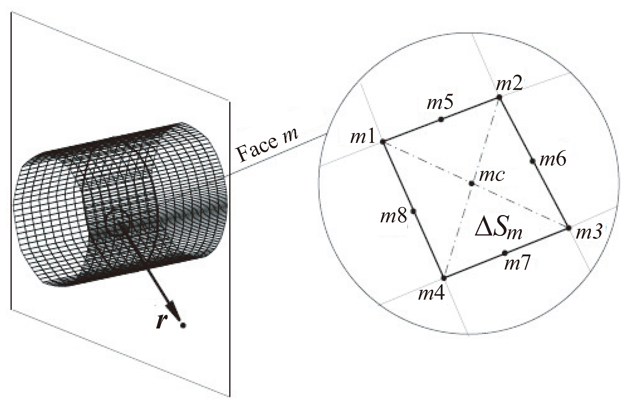
Then, the spatial discretization of the cylindrical control surface is performed. The control surface is presented in Figure 4. The total of the integrals over each face that the control surface is divided into is the surface integral over the control surface. Second-order quadrature formulae or fourth-order quadrature formulas (Simpson approach) are used to calculate the integral for each face. The integrand is calculated at nine points ( m 1 , m 2 , …, m 8 , and m c ) when utilizing fourth-order formulas, as opposed to the central point of the face m c when using second-order formulas.
1. Formulas of the second order. When using a second-order formula, the integrand is represented as
m = 1 M Q ( y m c , t n r m c / c 0 ) Δ S m ,
where
y m c = 1 4 y m 1 + y m 2 + y m 3 + y m 4 .
Here, t n is the observation time, x is the position of the observer, r m c = x y m c .
2. Formulas of the fourth order. When using a fourth-order formula, the integrand is represented as
m = 1 M i = 1 9 α i Q ( y m i , t n r m i / c 0 ) Δ S m i = 1 9 α i ,
where
y m c = 1 4 y m 1 + y m 2 + y m 3 + y m 4 .
Here, y m c = y m 9 . The points y m 1 , y m 2 , y m 3 , y m 4 correspond to the corner points of the face. The coordinates of the midpoints are found from the relations
y m 5 = 1 2 y m 1 + y m 2 , y m 6 = 1 2 y m 2 + y m 3 , y m 7 = 1 2 y m 3 + y m 4 , y m 8 = 1 2 y m 4 + y m 1 .
Here, t n is the observation time, x is the position of the observer, r m i = x y m i . The weighting coefficients have values α i = 1 if i = 1 , , 4 and α i = 16 if i = 5 , , 9 .
Based on values Q ( y m i , τ m ) , where τ m represents source time utilized in CFD calculations, integrand Q ( y m i , τ n ) , where τ n = t n r m i / c 0 , is computed using an interpolation approach. Generally speaking, τ n τ m . Density, velocity, and pressure distributions that vary with time are used to store information at the source. Finding time derivatives is required in order to compute surface integrals and integrands that are functions of density, velocity, and pressure and that depend on L ˙ i , U ˙ i , and M ˙ i . Relations between the second and fourth order of accuracy are applied to a non-uniform mesh in order to achieve this goal (Figure 5).
The source time τ m corresponds to CFD calculations. The time τ n is necessary for the numerical determination of integrals. Interpolation procedure is applied to obtain values between τ m and τ n .
1. Formulas of the second order. When using formulas of the second order of accuracy, interpolation from time point τ m to point τ n is performed
F ( τ n ) = F ( τ m ) τ n τ m 1 τ m τ m 1 + F ( τ m 1 ) τ m τ n τ m τ m 1 .
The time derivative is found as
F τ τ = τ n = F m ( τ n τ m 1 ) 2 F m 1 ( τ m τ n ) 2 ( τ m τ n ) ( τ n τ m 1 ) ( τ m τ m 1 ) + F n [ ( τ m τ n ) 2 ( τ n τ m 1 ) 2 ] ( τ m τ n ) ( τ n τ m 1 ) ( τ m τ m 1 ) .
2. Formulas of the fourth order. When using formulas of the fourth order of accuracy, interpolation from time point τ m to point τ n is performed
F ( τ n ) = a 0 + a 1 τ n + a 2 τ n 2 + a 3 τ n 3 .
The time derivative is found as
F τ τ = τ n = a 1 + 2 a 2 τ n + 3 a 3 τ n 2 .
Here,
a 1 = Δ 1 Δ = 3 τ i 2 + 6 τ i ( Δ τ ) + 2 ( Δ τ ) 2 6 ( Δ τ ) 3 F i 1 + 3 τ i 2 + 4 τ i ( Δ τ ) ( Δ τ ) 2 2 ( Δ τ ) 3 F i 3 τ i 2 + 2 τ i ( Δ τ ) 2 ( Δ τ ) 2 2 ( Δ τ ) 3 F i + 1 + 3 τ i 2 ( Δ τ ) 2 6 ( Δ τ ) 3 F i + 2 ; a 2 = Δ 2 Δ = τ i + Δ τ 2 ( Δ τ ) 3 F i 1 3 τ i + 2 Δ τ 2 ( Δ τ ) 3 F i + 3 τ i + Δ τ 2 ( Δ τ ) 3 F i + 1 τ i 2 ( Δ τ ) 3 F i + 2 ; a 3 = Δ 3 Δ = 1 6 ( Δ τ ) 3 F i 1 + 1 2 ( Δ τ ) 3 F i 1 2 ( Δ τ ) 3 F i + 1 + 1 6 ( Δ τ ) 3 F i + 2 .

7. Geometry and Grid

A jet of cold air exhausting from an axisymmetric conical nozzle into the surroundings is considered. The flow field is defined by the nozzle pressure ratio, NPR = p 0 / p , where p 0 is the total pressure at nozzle inlet, and p is the atmospheric pressure downstream of the nozzle. NPR varies from 1 to 10. To change NPR, the total pressure varies. The nozzle geometry and flow conditions are consistent with those described in [40,41,42,43]. The problem itself is considered as part of the international AIAA Propulsion Aerodynamics Workshop, dedicated to the comparison of various codes designed to solve CFD problems.
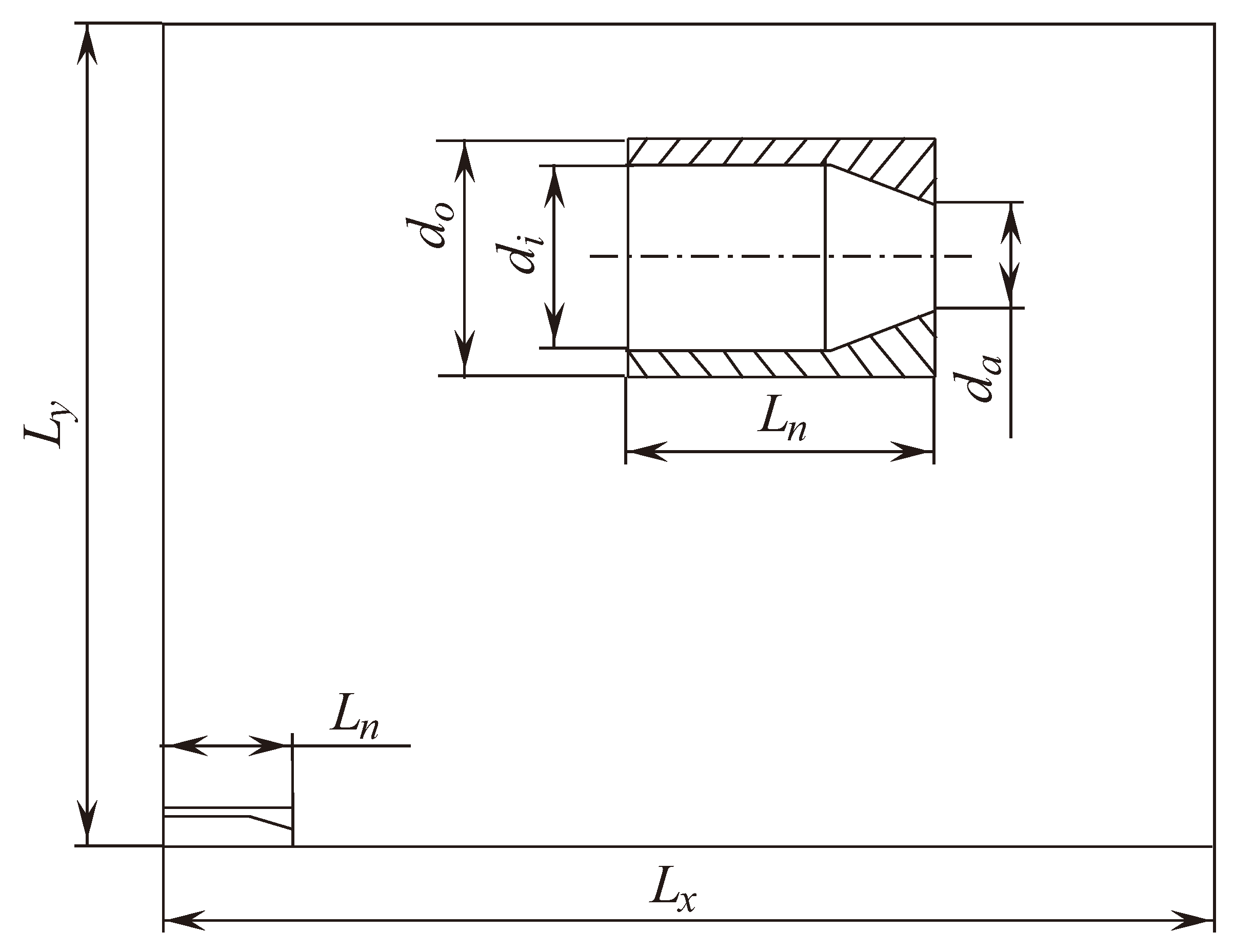
The diameter of the nozzle outlet is d a = 76.20 mm. The nozzle half-opening angle is θ a = 25 (Figure 6). The inner diameter of the cylindrical nozzle section is d i = 145.48 mm. Its outer diameter is d o = 185.20 mm.
The computational domain represents a cylinder [ 0 , L x ] × [ 0 , L y ] , where L x is length and L y is radius. The length of the domain is 82 d a downstream from the nozzle outlet, 12 d a upstream from the nozzle outlet (this distance equals the length of the nozzle section, L n , which includes a cylindrical section and a conical nozzle), 38 d a in the radial direction.
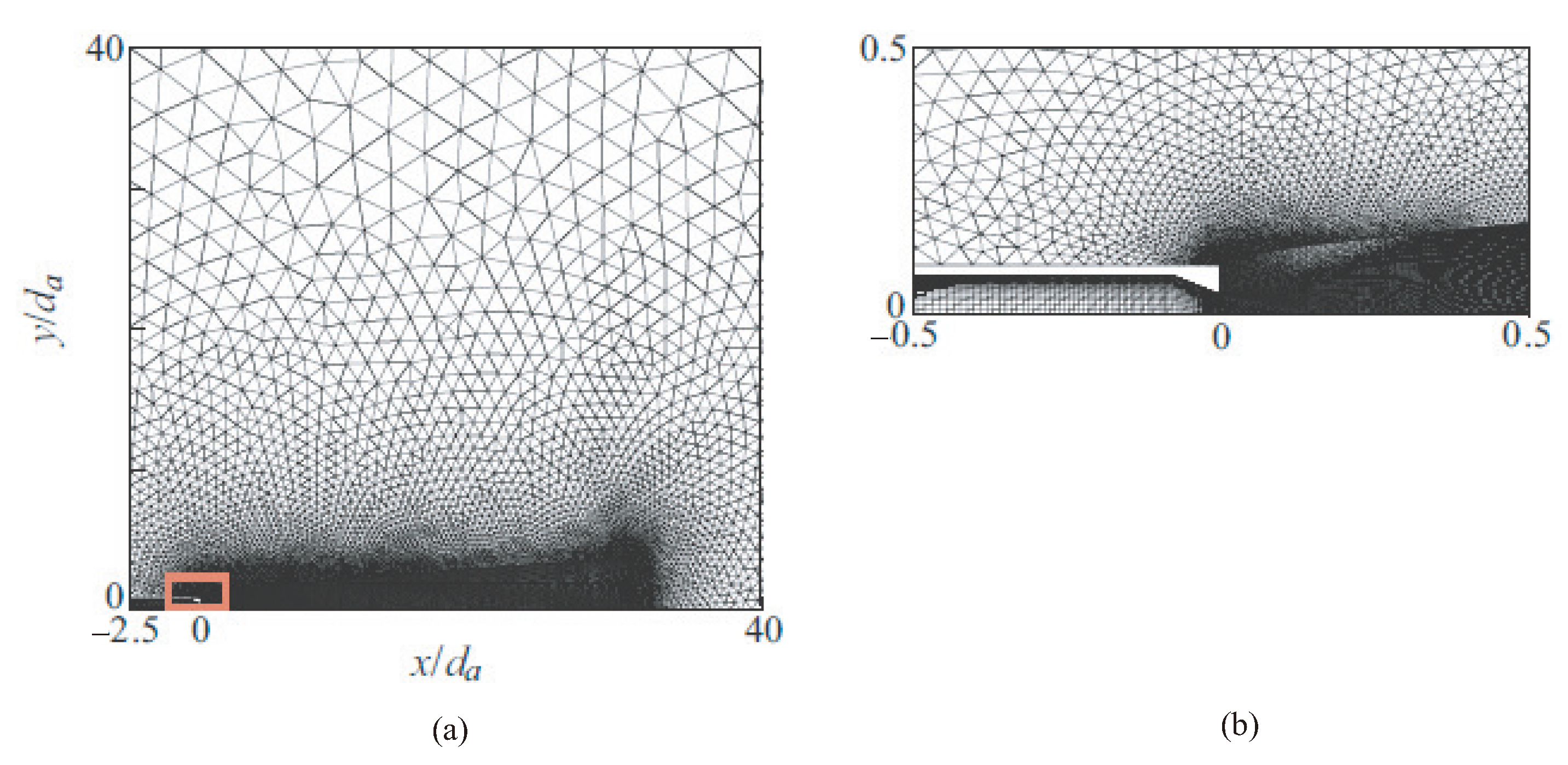
The calculations are performed with a block-unstructured grid (Figure 7). The structured part of the grid (quadrangular elements) is applied to the nozzle and jet region at a distance of about 18 outlet diameters. The unstructured part of the grid (triangular elements) is used in the far-field region. Inside the nozzle, a uniform grid is generated in the flow direction (x direction) and a stretched grid in the radial direction (y direction), with nodes clustered near the nozzle wall. CFD calculations are performed on a grid containing 210 × 90 nodes. The grid step size in the radial direction near the nozzle wall is about 1.86 × 10 5 m ( y + 1.4 ). The grid has about 352 nodes in the axial direction and about 210 nodes in the radial direction downstream of the nozzle outlet. The grid is refined near the jet flow region, providing high resolution of shear-layer instability waves, shock wave structures, and the propagation of acoustic waves in the near field. The grid is coarsened towards the output boundaries.
Initial calculations are carried out with URANS and Realizable k ε turbulence model. The values of empirical constants change as recommended in [14]. The results computed are compared with experimental data presented in [40,43].
Velocity, density, and temperature profiles are specified in the jet region at the initial time. The total pressure p 0 is set on the boundaries of the computational domain, and the total temperature T 0 , corresponding to stagnation temperature in the receiver ( T 0 = 288 K), is specified. The level of initial turbulence in the jet is determined by setting the intensity of fluctuations of flow velocity in the nozzle equal to 0.1%, and the ratio of turbulent to laminar viscosities equal to 1. At the outer boundary of the domain, the pressure and temperature in the surrounding are fixed at p = 10 5 Pa and T = 288 K. On the inner and outer walls of the nozzle, no-penetration and no-slip boundary conditions are used for velocities and adiabatic boundary conditions for temperature.
At the first stage, a stationary calculation of the jet flow quantities is carried out. For the stationary problem to converge, about 2000 iterations are required. At the second stage, unsteady calculations are carried out with a time step of 2.1 × 10 6 s. The time step is found from the experimental data on jet frequency characteristics. To obtain averaged flow, turbulence quantities, and noise levels, statistics are collected, the time length of which is 28 d a / u a . Sound pressure levels are calculated from unsteady flow quantities recorded on conical Kirchhoff surfaces enveloping the jet.
A tiny portion of the domain behind the nozzle exit is designated as a zone of laminar flow in the computations. As a result, the mixing layer’s instability waves can be more strongly excited. The flow is regarded as turbulent in the remaining portion of the region. It is positioned 500 wavelengths away from the nozzle exit to prevent wave reflection from the output boundary. The numerical viscosity causes the acoustic waves to disperse. The computational grid is coarsened toward the output boundary (big cells have a size of around 25 times the wavelength).
Sound pressure levels are calculated from unsteady flow quantities recorded on conical Kirchhoff surfaces enveloping the jet (Figure 8). Unsteady flow quantities on the Kirchhoff surface are recorded after obtaining a developed vortex structure in the jet mixing region for 5 × 10 4 time steps (the time step is 1.78 × 10 6 s). Kirchhoff surface data are used to numerically integrate the inhomogeneous wave equation FW–H to calculate the sound pressure at selected observation points.
Far-field acoustic pressure pulsation spectra are calculated based on the fast Fourier transform using the Hanning window. The pressure pulsation spectra are additionally averaged in the azimuthal direction.

8. Results and Discussion

An air jet exhausting from a conical nozzle into a surrounding is considered with various NPRs.

8.1. Jet Structure

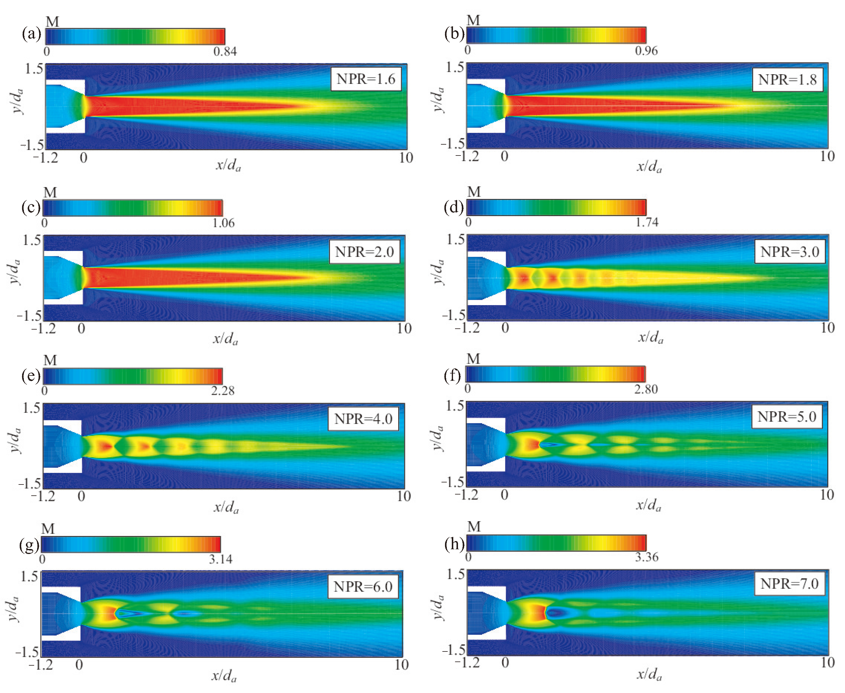
Figure 9 displays the contours of the Mach number. The flow is subsonic when NPR goes from 1.42 to 1.82, and supersonic when NPR increases to 2 (the crucial pressure ratio for air is 1.9). At NPR = 4 , the Mach disk is clearly apparent. Along with a rise in pressure ratio, the Mach disk’s size also grows, and the Mach disk itself tends to move downstream.
The results computed describe well the structure of steady-state supersonic non-isobaric jets. The structure of the jet’s initial region is characterized by the presence of shock waves, rarefaction waves, and a mixing layer. A diamond structure of a free supersonic underexpanded jet is clearly reproduced. It includes a shock wave, reflected shock wave, Mach disk, jet boundary, and shear layer formed behind the triple point. In a supersonic underexpanded jet, the jet core with its wave structure and the mixing zone are distinguished. The mixing zone is located at the jet boundary, coming from the nozzle outlet. It expands downstream and covers the entire flow at a sufficient distance. Three regions are distinguished: (i) the initial region, where flow strongly depends on the Reynolds number, nozzle diameter, the characteristics of flow in the nozzle, and the nozzle’s opening angle; (ii) the transition region, which is characterized by the closure of mixing layers and significant flow turbulization; (iii) the main region, where average flow becomes self-similar. The point on the jet centerline corresponding to distance x n , where the mixing zone closes, characterizes the end of the initial region. If x > x n , supersonic speeds are maintained, gradually decreasing to the speed of sound at a certain point x s on the jet axis. The segment between coordinates x n and x s represents the transition region. If x > x s , the subsonic region of the jet starts. Another characteristic of a supersonic underexpanded jet is the average barrel size, which is the average size of the second, third and fourth barrels of the jets. The flow in the second and subsequent jet barrels, the lengths of which monotonically decrease compared to the length of the first barrel, is characterized by the regular interaction of oblique shock waves. The point of intersection of these waves is located on the jet centreline. Inside the supersonic jet, regions of subsonic flow appear behind the shock waves.
The high radial gas speed in non-isobaric jets creates a complicated flow with expansion and compression zones as well as shock waves in a variety of configurations, which in turn determines the jet structure. Along the jet length, the radial velocity at the jet boundary turns out to be variable and can change direction multiple times before becoming negligible. This causes a series of distinctive, roughly comparable structures to emerge at a specific distance from the nozzle outlet. As the mixing layer grows along the jet boundary, viscosity factors cause the outlines of these structures to gradually become less distinct.
The outcomes, expressed as the density gradient absolute value, are displayed in Figure 10 alongside the shadow flow pattern extracted from [43]. Two to three cells are covered by the shock wave. At x / d a = 1.23 , the shock wave and jet centerline intersect. The calculated angle of shock inclination to jet centerline is 49 , which agrees well with the 47 value found in experimental data [42].

8.2. Local Quantities

Figure 11 shows the distributions of turbulence kinetic energy and Mach number along the jet centerline. The supersonic flow is decelerated smoothly to a subsonic speed through the system of shock waves. These shock waves (diamond structure of the supersonic jet) are visible in the figure presented (oscillations in Mach number in the initial part of the distribution are presented).
A series of shock waves forms at the nozzle outlet. Near the jet centerline, a supersonic jet cellular structure with discernible velocity distribution minimums and maximums is seen. The first and second cells of the jet are located based on the variation of peaks and minima. The boundaries of cells match the speed minima. The shocks stop around 10 diameters from the nozzle outlet. The Mach number gradually drops in an axial direction downstream. There is turbulence in the shear layer. Sharp velocity gradients at the nozzle outlet cause a significant increase in turbulence energy. The kinetic energy profile gradually smooths out, its values decrease downstream, and as the jet speed drops as it interacts with the surrounding air.
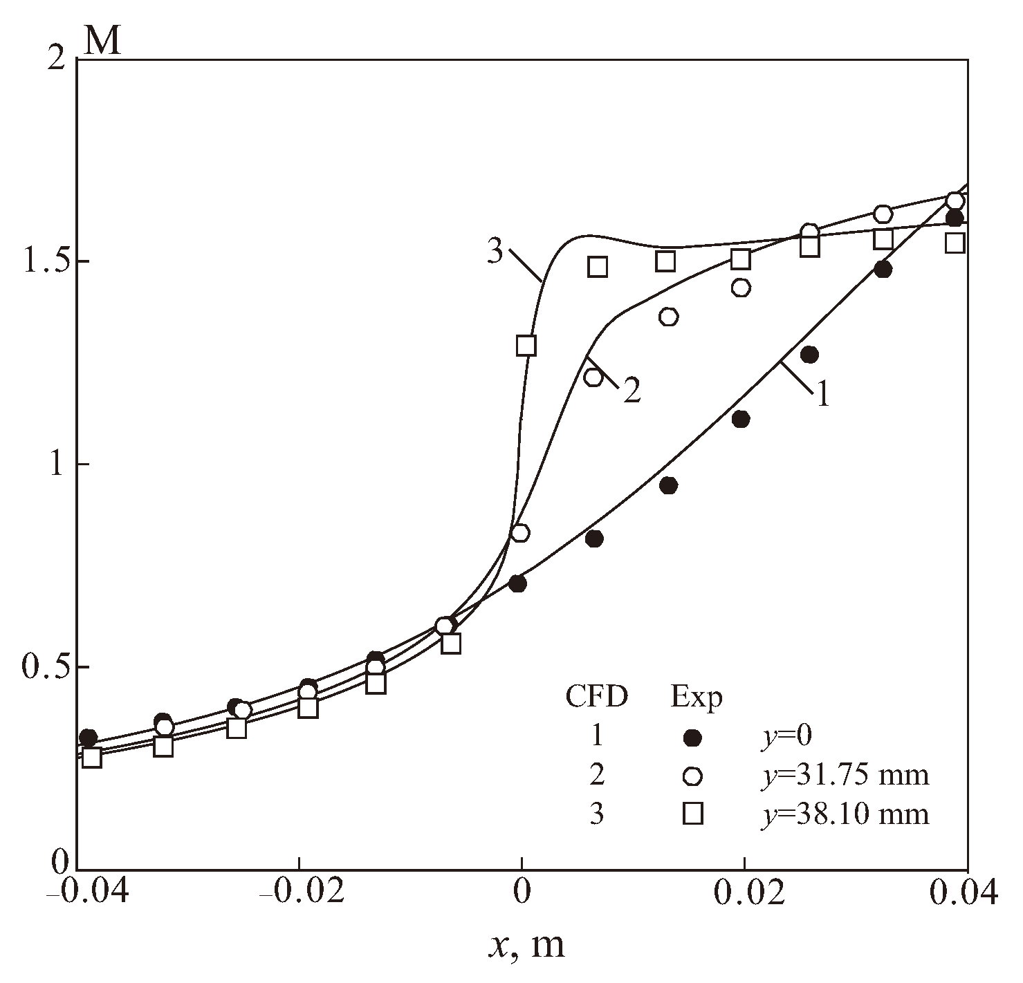
Figure 12 displays the axial distribution of Mach number at the fixed radial position. Symbols and solid lines, respectively, represent experimental data and numerical simulation results, according to [43]. There is a good comparison between computational and experimental results.
The flow in a conical converging nozzle is non-uniform. To find the shape of a sonic line and compare it with experimental measurements of static pressure on the nozzle wall and jet centerline presented in [40], the Mach number is calculated as
M w = 2 γ 1 p 0 p w γ 1 γ 1 1 / 2 .
A Mach number M w = 1 corresponds to the position of the sonic line on a nozzle surface (supersonic regime occurs if NPR > 2 ).
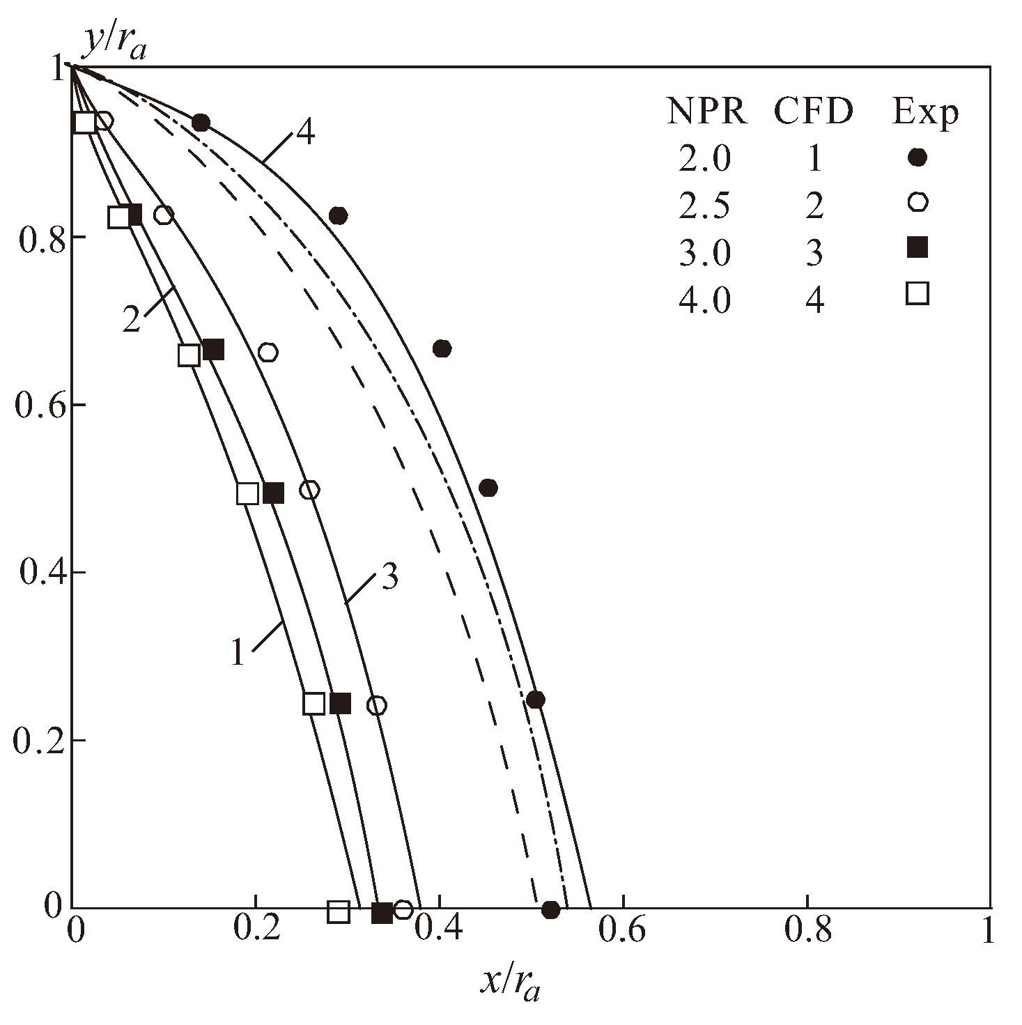
In Figure 13, the sonic line shape for a range of pressure ratios is displayed. Symbols represent experimental data, and solid lines represent computational results [43]. The sonic line on the jet centerline is located at approximately half the nozzle radius from the output. The sonic line advances in the direction of the nozzle exit as NPR rises. The location and form of the sonic line remain unchanged when a critical pressure ratio is exceeded, and the discharge coefficient likewise stays essentially unchanged. NPR * = 4 in computations, which is in good agreement with measurements made experimentally [40]. The jet structure is significantly influenced by the pressure ratio.
The grid sensitivity of the results is assessed using the shape of the sonic line presented in Figure 13 for the fixed NPR. The dashed line shows results computed with the coarse grid, the dashed–dotted line show results computed with the intermediate grid, and the solid line shows results computed on the fine grid. The fine grid consists of N cells, and the coarse and intermediate grids contain N / 4 and N / 2 cells.
The choice of grid resolution in different blocks of the grid is based on the previous experience with nozzle and supersonic jet flows. A grid sensitivity study consists of running the same simulation using grids with different resolutions and analyzing how much the converged solution changes with each grid. The grid convergence index (GCI) proposed in [44] is applied. Special attention is paid to the grid block near the outlet boundary of the nozzle, where high gradients of flow quantities are expected.
The main convergence criterion considered in the presented simulations is the divergence of the velocity field, representing the conservation of continuity. The chosen tolerance, ranging between 10 6 and 10 8 in the simulations presented, should reflect the expected length and time scales of the flow field.

8.3. Discharge and Thrust Coefficients

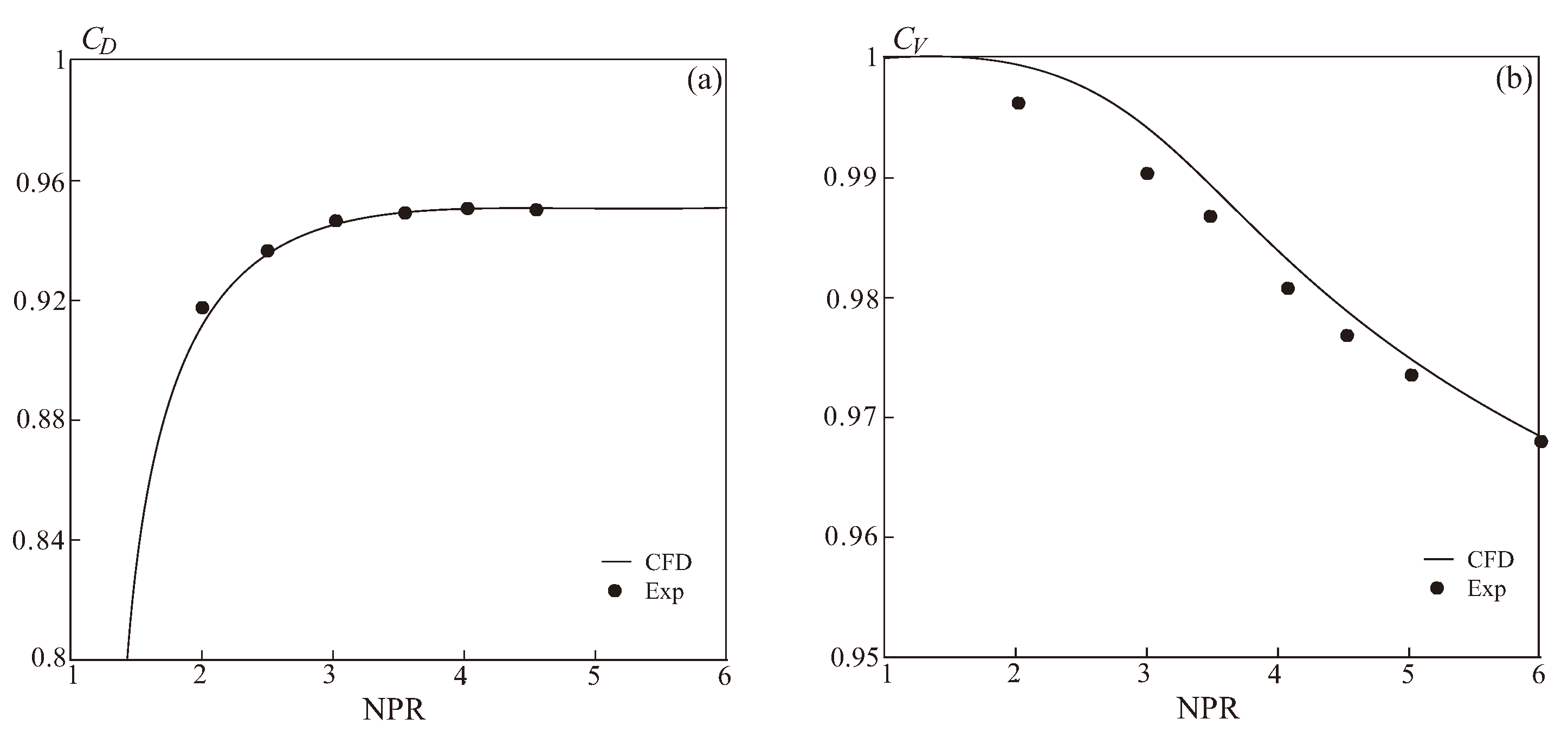
Comparison with experiment and calculations available in the literature is carried out using discharge coefficient and thrust coefficient. The discharge coefficient differs from unity due to the non-uniform distribution of flow quantities in nozzle cross sections and the presence of boundary layers on nozzle walls [17]. The discharge coefficient is defined as the ratio of actual flow rate to the ideal flow rate if flow is isentropic ( C D = G / G j ). The discharge coefficient is found as
C D = 2 π S ρ j U j A j , S = 0 r a ρ u r d r .
The ideal flow rate is found with one-dimensional nozzle theory and isentropic relationships [17]
G j = p 0 A j ( R T 0 ) 1 / 2 2 γ γ 1 p a p 0 2 γ p a p 0 γ + 1 γ 1 / 2 ,
where p a = p . The flow rate for isentropic flow increases with increasing inlet pressure. The critical NPR is
NPR * = 2 γ + 1 γ γ 1 .
Then, the flow rate reaches a maximum and it is found as
G j max = p 0 A j ( R T 0 ) 1 / 2 2 γ γ + 1 2 γ + 1 2 γ 1 1 / 2 .
If the pressure ratio further increases, the flow rate does not change. The critical value of pressure ratio depends only on the ratio of specific heat capacities (for air, γ = 1.4 ). It is NPR * = 1.89 . The critical value corresponds to the formation of a local speed of sound in nozzle outlet. In this case, calculations carried out at a nozzle pressure ratios of 1.3, 1.6, and 1.8 correspond to subcritical regime, when the ideal flow rate is determined by an expression depending on pressure ratio. Other calculations, carried out starting from NPR = 1.9 , correspond to supercritical regimes, when underexpanded flow from the nozzle is observed, and the ideal nozzle flow rate (with an isentropic outflow) reaches its maximum value.
The nozzle thrust coefficient allows us to evaluate the internal flow losses. It is defined as the ratio of actual nozzle thrust to the ideal nozzle thrust corresponding to full expansion when p a = p and absence of internal losses due to viscous effects ( C V = P / P j ). The thrust coefficient is found as
C V = 2 π Q U j S , Q = 0 r a [ ρ u 2 ( p p ) ] r d r .
The ideal nozzle thrust is found as P j = G U j . The flow rate is determined in calculations at the nozzle outlet. The isentropic velocity is calculated theoretically. When the nozzle operates in the off-design mode, the pressure at the nozzle outlet is not equal to the surrounding pressure ( p a p ). In this case, the due nozzle thrust is determined by the integral value P 1 , which depends on the local distributions of density and velocity. The nozzle thrust is the product of pressure difference and nozzle outlet cross-sectional area P 2 = A ( p a p ) .
The discharge and thrust coefficients are found by integrating the local density and velocity radial distributions in nozzle outlet. The flow quantities in isentropic flow are found as
U j = M j γ R T j 1 / 2 ; M j = 2 γ 1 NPR ( γ 1 ) / γ 1 1 / 2 ; T j = T 0 1 + γ 1 2 M j 2 1 .
The nozzle outlet cross-sectional area is A j = 322.35 mm2.
Figure 14 displays the nozzle thrust and discharge coefficient for different nozzle pressure ratios, compared to measurements [43]. The discharge coefficient estimated values (solid lines) correspond well with the experimental data (symbols •). When the pressure ratio rises to 2, the discharge coefficient increases dramatically before staying rather steady after that. At low nozzle pressure ratios, the discharge coefficient is nearly constant; as the pressure ratio rises, it decreases by 4–5%. Regarding the discharge coefficient, the computational and experimental data agree well; however, the CFD findings overestimate the nozzle thrust coefficient by approximately 2–2.5% when compared to the measurements.
The standard thrust coefficient is computed over the radius of the nozzle exit r a using the local density, local streamwise velocity, and local radius from the centerline. It is clear from the definition of the thrust coefficient equation that only the force across the jet exit is considered. However, the nozzles had a large base region, and there was surely a significant force on the base region that could have affected the experimental thrust measurements and calculations. Therefore, a new total thrust coefficient could be computed using integration over radius r n , where r n is the radius to the outer edge of the nozzle exterior, which includes the large base area.

8.4. Noise Generation

The computation of far-field acoustic noise resulting from a compressed turbulent jet is considered. The problem primary determining parameters is the Reynolds number ( 1.2 × 10 6 ). It is derived from quantities on the nozzle exit. Another non-dimensional number is the Mach number of a fully expanded jet. It is equal to 0.89. In this scenario, time step is 10 7 s, or around 2 × 10 6 steps for the whole computation. A time step value of (CFL∼0.8) is chosen based on the Courant condition.
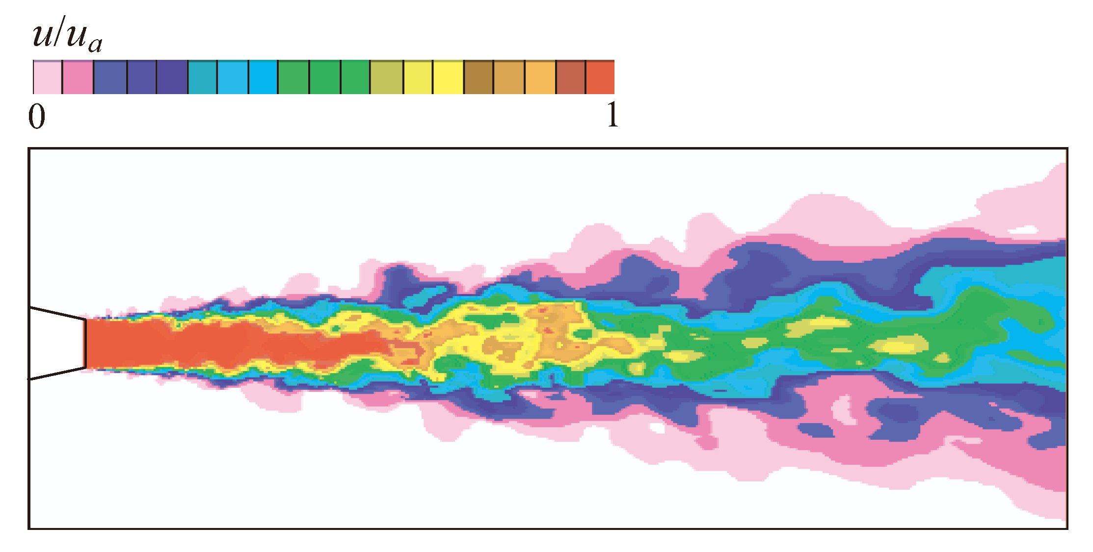
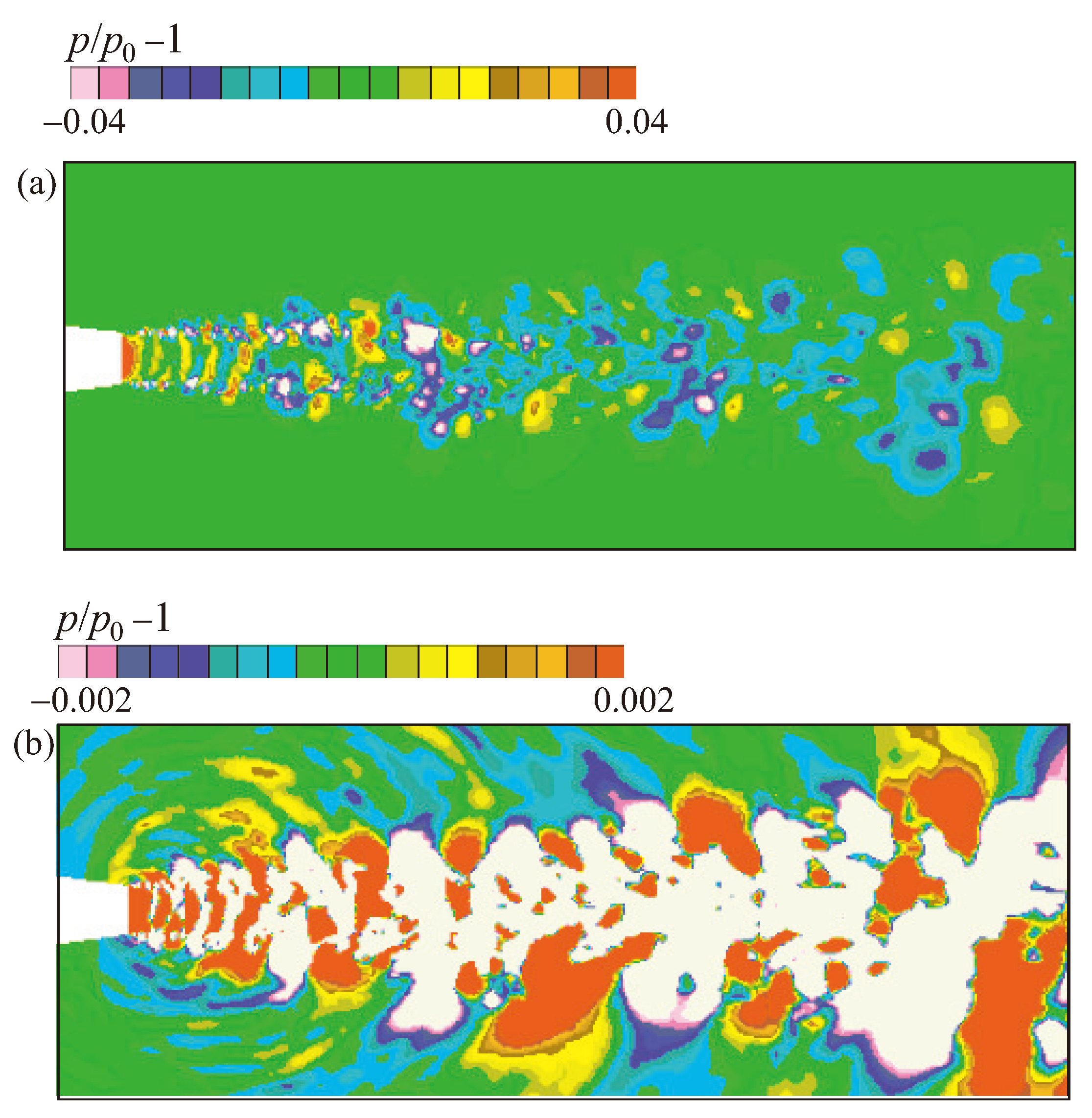
In Figure 15, the instantaneous velocity field is displayed. Figure 16 displays two variants of the instantaneous pressure fields, which correspond to the selected flow and acoustic scales of pressure drop. On an auditory scale, low-frequency waves are easily discernible via pressure distribution. Figure 17 displays the contours of the pressure derivative.
The acoustic analogy method is used to compute sound pressure. In order to achieve this, a certain surface that surrounds the jet from the outside is assigned. It is from this surface that the pressure, density and velocity values are obtained for computation. A unique procedure that computes the integral FW–H then processes these data. In the range of polar angles 22–163°, the noise level is measured at sites situated at a distance of r = 96 d a from the nozzle outlet, where d a is diameter of nozzle outlet.
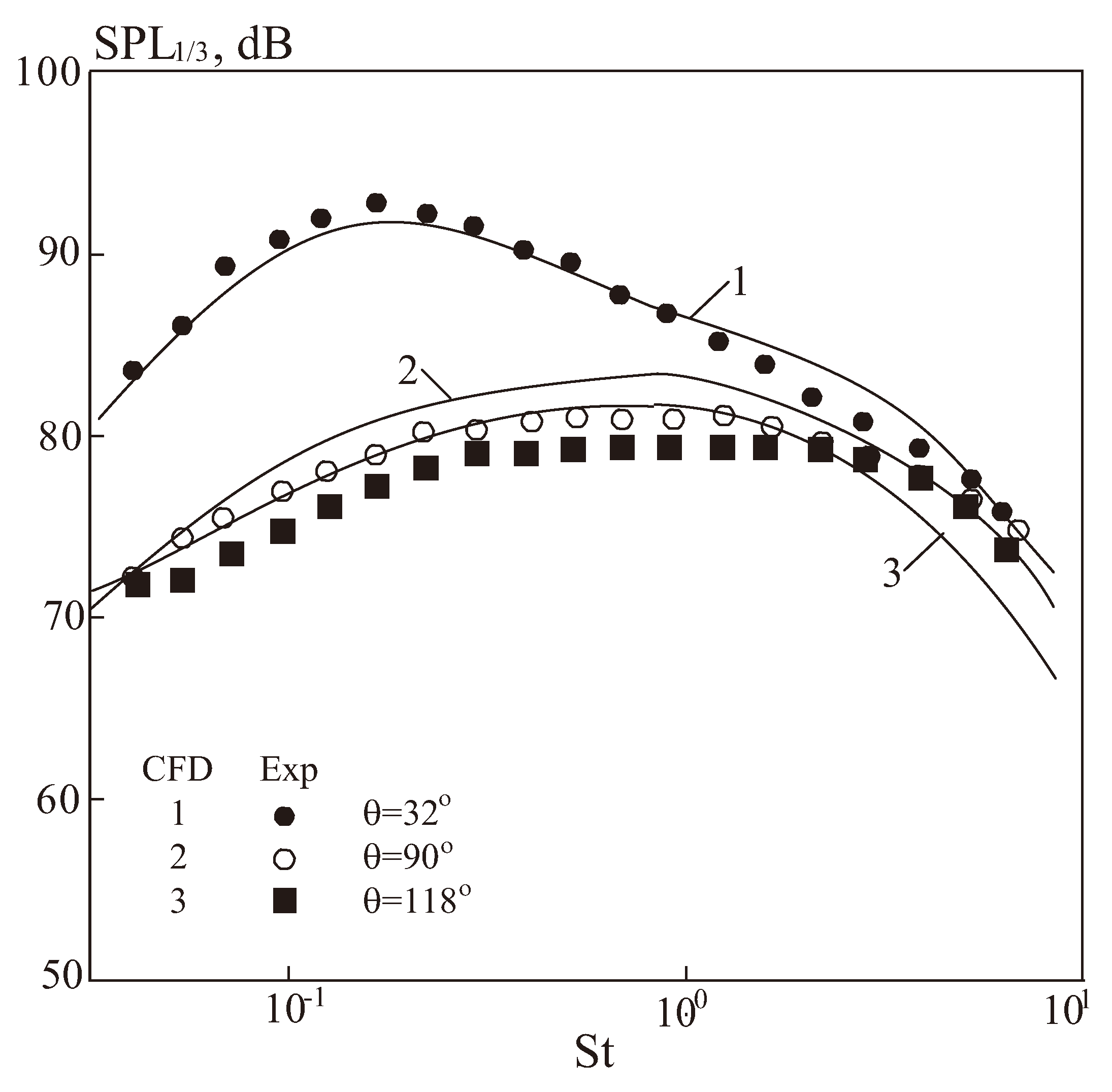
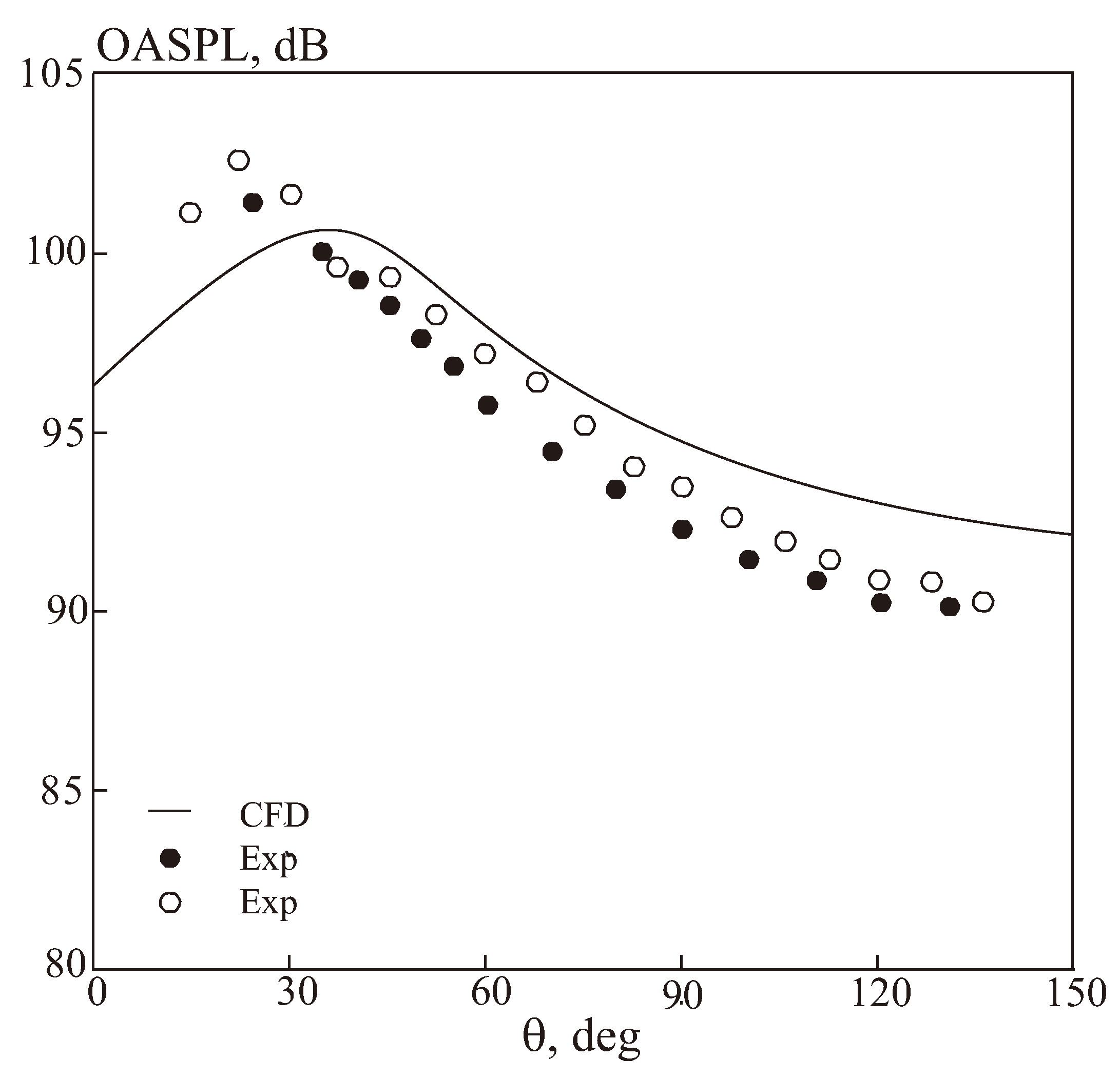
Ten azimuthal angles are used to further average the acquired data. Figure 18 displays a comparison between the third-octave far-field noise spectra and experimental data [45]. Figure 19 displays a comparison of the directivity patterns of supersonic jet integral noise with measurements [45,46]. Within the range of Strouhal numbers 0.02 < St < 1.5 , the spectra correlate well with the experimental results. The integral level of the spectral energy matches the experimental one, and it is spread pretty evenly, with a bias towards higher frequencies.
At r / D = 53 , the experimental data from [47] (symbols) is compared with calculated distributions (solid lines) of the integral SPL in the circumferential direction at the nozzle outlet, corresponding to the subsonic outflow regime, as can be seen in Figure 20.
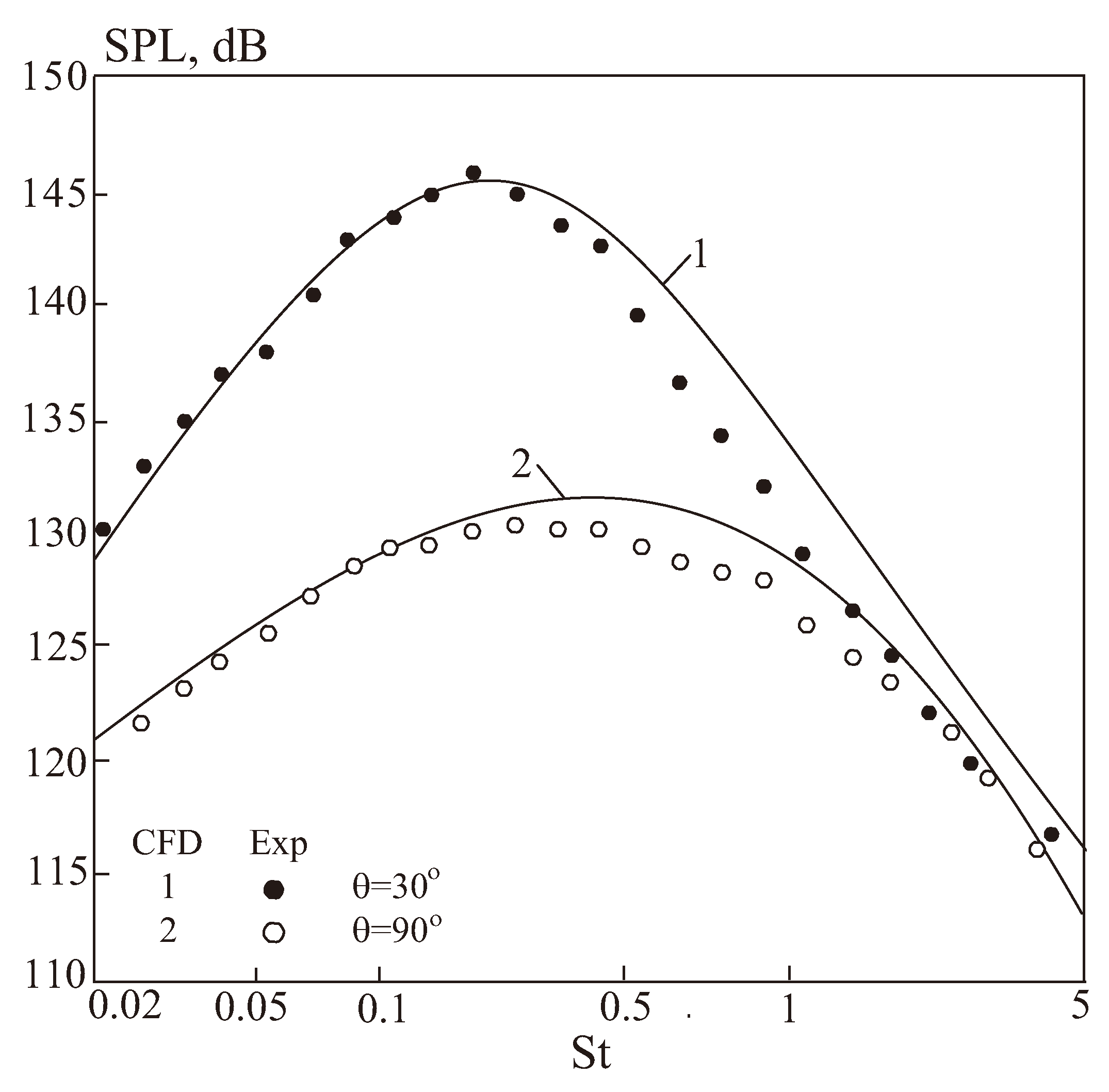
Figure 21 compares the frequency distribution of the sound pressure level with the experimental data from [47] (symbols • and ∘) for various angular coordinates ( M = 0.72 ).
Three types of noise are present in a supersonic non-isobaric jet: discrete tone, broadband shock wave, and turbulent mixing noise. Because of their supersonic convective speed, turbulent structures moving in the mixing layer interact with the surrounding flow to produce jet mixing noise. These interactions take the form of Mach waves, which are disturbance fronts radiated into the environment at the Mach angle. Due to the unique attenuation coefficient and strengthening of the vortex structures, radiation arises from different parts of the jet length at different angles depending on the wave number.
Only in supersonic jet outflow off-design states does shock wave noise manifest itself. Large-scale vortex structures in the mixing layer generate this noise when they pass through oblique and direct shock waves, which increases the amplitude of the large-scale vortex structures’ oscillations. Pressure rises in one area of a vortex and falls in the other as it moves through a shock wave behind the shock wave front. As a result, pressure and rarefaction waves are created and start to move in various directions within the vortex. The system then starts to behave like a dipole source of radiation. Shock wave noise emission output is directly proportional to the jet kinetic energy. The discrete tone corresponds to the jet shock wave noise. The primary distinction in this instance noise creation mechanism is the existence of the acoustic feedback phenomena. The thin mixing layer close to nozzle exit is impacted by shock wave noise emanating from the gas-dynamic barrel boundaries that are travelling against the jet flow. As a result, there are more disturbances in this self-oscillating system, where oscillations arise at a specific frequency and amplify the pulsations (oscillations of a discrete tone are produced in the noise spectrum of a supersonic non-isobaric jets). Because of acoustic feedback, the discrete tone intensity is dependent on various factors, for example nozzle geometry, jet temperature, and ambient conditions.
The majority of a supersonic off-design jet’s noise is produced by intense discrete sound radiation that happens when the acoustic feedback mechanism is stimulated by a quasi-periodic shock wave structure. Upstream acoustic waves contact with the nozzle’s edge and cause instability waves to form in the thin mixing layer at the exit section. The amplitude of these instability waves rises as they travel downstream. An acoustic wave is then produced as a result of their interaction with the periodic shock wave structure. The resultant wave travels upstream and is directed outside the jet and toward the nozzle’s edge. The loop closes when the wave hits the nozzle’s edge and starts a new wave of instability. The wavelength of instability, which has its own dynamics, and the phase velocity of disturbances eventually define the frequency of a discrete tone.
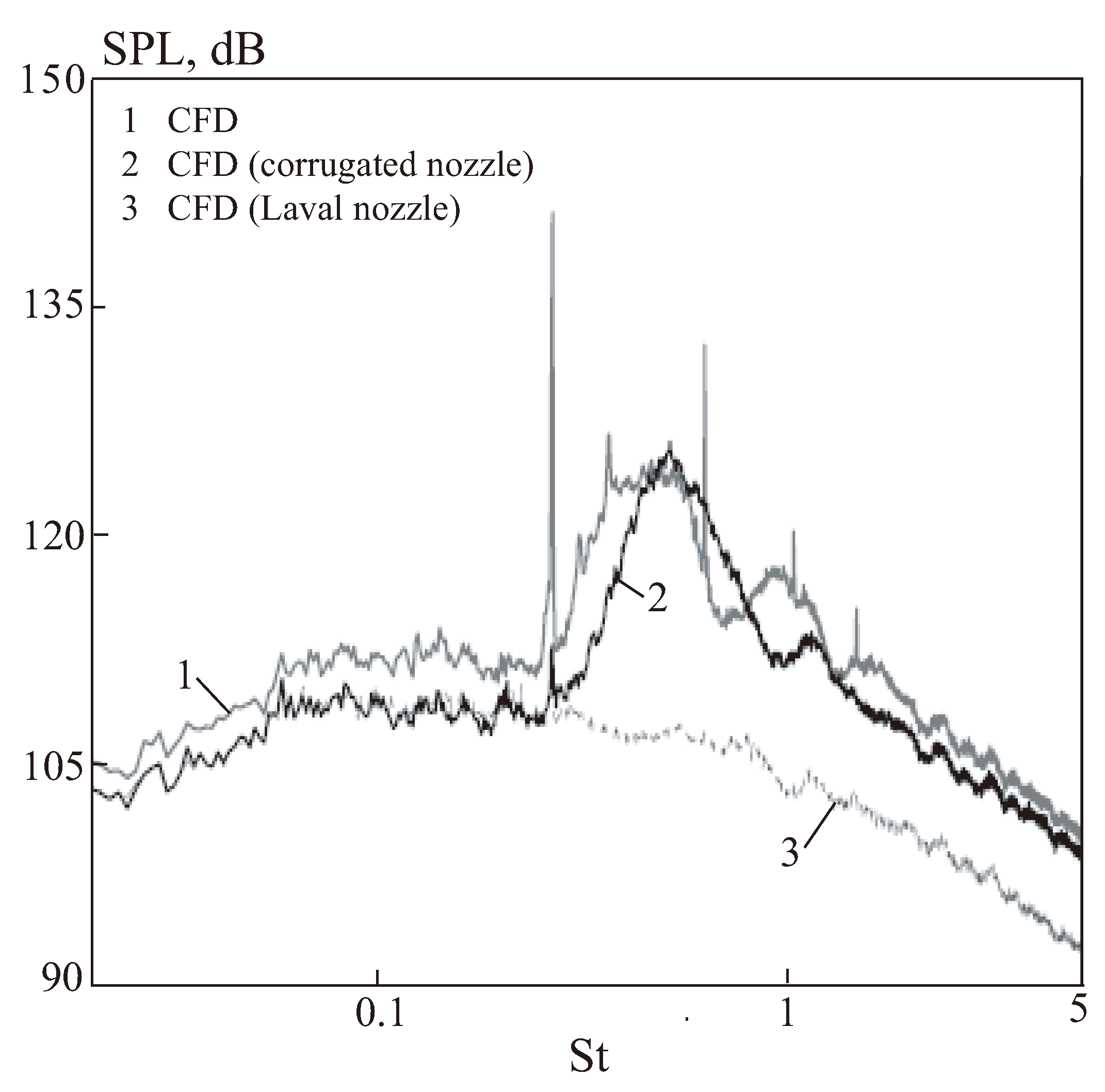
The spectrum of sound pressure in a supersonic jet is shown in Figure 22 at φ = 110 ( r / D = 52 ). Line 1 corresponds to numerical calculations of the jet flowing from a tapering conical nozzle. Lines 2 and 3 are taken from the work of [48] and correspond to the outflow of a jet from a corrugated nozzle, which makes it possible to suppress the screech effect, and the Laval nozzle.
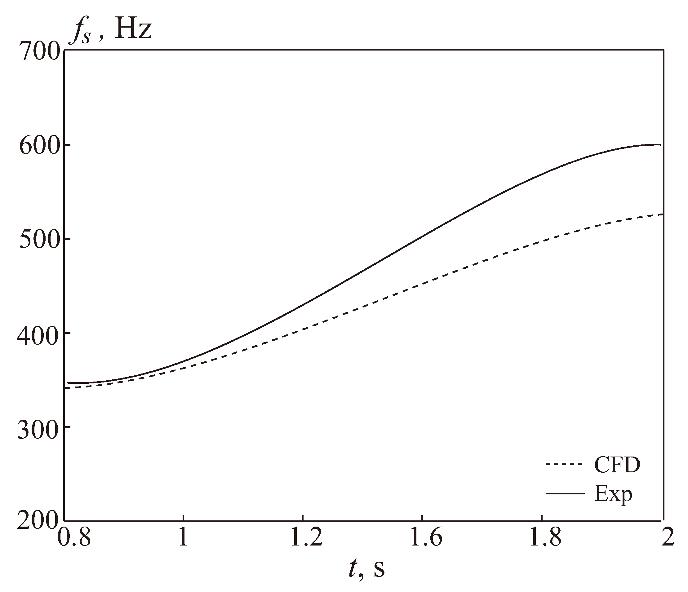
Figure 23 presents the discrete tone frequency calculation results compared with experimental data. The dynamics of the process are rather accurately described by the model. The primary distinction is that the experiment shows a faster increase in discrete tone frequency than the model does.

9. Conclusions

The impact of the pressure drop on the shock wave structure of a supersonic jet emerging from a conical nozzle, as well as the distribution of parameters along the jet axis, were demonstrated by numerical simulation. The shock wave structure of the jet is fairly accurately reproduced by the calculation results at different pressure drops, and the local and integral flow parameters correspond well with the physical experiment data, according to a comparison of the derived results with the experimental data. According to the computation results, it is possible to reproduce both the turbulent mixing noise, which originates at the end of the potential core and the supersonic zone of the jet, and the broadband noise from shock wave cells, which propagate primarily in the lateral direction and upstream, Mach waves.

Funding

This research received no external funding.

Institutional Review Board Statement

Not applicable.

Informed Consent Statement

Not applicable.

Data Availability Statement

The data presented in this study are available on request from the corresponding author.

Conflicts of Interest

The author declares no conflicts of interest.

References

  1. Smirnov, N.N. Ensuring safety of space flights. Acta Astronaut. 2017, 135, 1–5. [Google Scholar] [CrossRef]
  2. Smirnov, N.N. Space flight safety: Past and future. Acta Astronaut. 2022, 194, 353–357. [Google Scholar] [CrossRef]
  3. Raman, G. Supersonic jet screech: Half-century from Powell to the present. J. Sound Vib. 1999, 225, 543–571. [Google Scholar] [CrossRef]
  4. Nguyen, D.T.; Maher, B.; Hassan, Y. Effects of nozzle pressure ratio and nozzle-to-plate distance to flowfield characteristics of an under-expanded jet impinging on a flat surface. Aerospace 2019, 6, 4. [Google Scholar] [CrossRef]
  5. Cui, K.; Liu, H.; Jiang, W.; Yu, D. Thrust noise cause analysis and supression of a cusped field thruster. Acta Astronaut. 2021, 179, 322–329. [Google Scholar] [CrossRef]
  6. Chiu, H.H.; Sommerfield, M. Theory of combustion noise. Acta Astronaut. 2024, 1, 967–984. [Google Scholar] [CrossRef]
  7. Chin, C.; Li, M.; Harkin, C.; Rochwerger, T.; Chan, L.; Ooi, A. Investigation of the flow structures in supersonic free and impinging jet flows. J. Fluids Eng. 2013, 135, 031202. [Google Scholar] [CrossRef]
  8. Zapryagaev, V.; Kiselev, N.; Gubanov, D. Shock-wave structure of supersonic jet flows. Aerospace 2018, 5, 60. [Google Scholar] [CrossRef]
  9. Boyko, V.M.; Dostovalov, A.V.; Zapryagaev, V.I.; Kavun, I.N.; Kiselev, N.P.; Pivovarov, A.A. Study of the structure of supersonic non-isobaric jets. Sci. Notes TsAGI 2010, 41, 44–57. [Google Scholar]
  10. Emami, B.; Bussman, M.; Tran, H. Application, realizability and shock unsteadiness to kε simulations of under expanded axisymmetric supersonic free jets. J. Fluids Eng. 2010, 132, 041104. [Google Scholar] [CrossRef]
  11. Nichols, D.S. Accounting for Shocks in the Ke–Kw Turbulence Model. In Proceedings of the 41st AIAA Fluid Dynamics Conference and Exhibit, Honolulu, HI, USA, 27–30 June 2011. [Google Scholar]
  12. Oh, Y.H.; Bushnell, D.M. Influence of External Disturbances and Compressibility on Free Turbulent Mixing; NASA Report SP-347; NASA: Washington, DC, USA, 1975. [Google Scholar]
  13. Sarkar, S. Modeling the Pressure-Dilatation Correlation; NASA Report CR-187566; NASA: Washington, DC, USA, 1991. [Google Scholar]
  14. Thies, A.T.; Tam, C.K.W. Computation of turbulent axisymmetric and nonaxisymmetric jet flows using the k–epsilon model. AIAA J. 1996, 34, 309–316. [Google Scholar] [CrossRef]
  15. Tam, C.K.W.; Auriault, L. Jet mixing noise from fine-scale turbulence. AIAA J. 1999, 37, 145–153. [Google Scholar] [CrossRef]
  16. Khavaran, A.; Kenzakowski, D.C.; Mielke Fagan, A.F. Hot jets and sources of jet noise. Int. J. Aeroacoustics 2010, 9, 491–532. [Google Scholar] [CrossRef]
  17. Alam, M.M.A.; Setoguchi, T.; Matsuo, S.; Kim, H.D. Nozzle geometry variations on the discharge coefficient. Propulsionand Power Res. 2016, 5, 22–33. [Google Scholar] [CrossRef]
  18. Kim, J.-H.; Kearney-Fischer, M.; Samimy, M.; Gogineni, S. Far-field noise control in supersonic jets from conical and contoured nozzles. J. Eng. Gas Turbines Power 2011, 133, 081201. [Google Scholar] [CrossRef]
  19. Emelyanov, V.N.; Tsvetkov, A.I.; Volkov, K.N. Mechanisms of generation and sources of noise in supersonic jets. J. Akustika 2019, 32, 144–150. [Google Scholar] [CrossRef]
  20. Ignatius, J.K.; Sankaran, S.; Kumar, A.R.; Satyanarayana, T.N.V.; Chakravarthy, S.R. Suppression of jet noise by staged water injection during launch vehicle lift-off. Int. J. Aeroacoustics 2008, 7, 223–241. [Google Scholar] [CrossRef]
  21. Sankaran, S.; Ignatius, J.K.; Ramkumar, R.; Satyanarayana, T.N.V.; Chakravarthy, S.R.; Panchapakesan, N.R. Suppression of high mach number rocket jet noise by water injection. J. Spacecr. Rocket 2009, 46, 1089–1099. [Google Scholar] [CrossRef]
  22. Zoppellari, E.; Juve, D. Reduction of Hot Jet Noise by Water Injection; AIAA Paper 98-2204; AIAA: Reston, VA, USA, 1998. [Google Scholar]
  23. Kandula, M. Effective Jet Properties for the Estimation of Turbulent Mixing Noise Reduction by Water Injection; AIAA Paper 2007-3645; AIAA: Reston, VA, USA, 2007. [Google Scholar]
  24. Tam, C. Supersonic jet noise. Annu. Rev. Fluid Mech. 1995, 27, 17–43. [Google Scholar] [CrossRef]
  25. Ffowcs-Williams, J.E. The noise from turbulence convected at high speed. Philos. Trans. R. Lond. 1963, A255, 469–503. [Google Scholar]
  26. Phillips, O.M. On the generation of sound by supersonic turbulent shear layers. J. Fluid Mech. 1960, 9, 1–28. [Google Scholar] [CrossRef]
  27. Tam, C.K.W.; Chen, P.; Seiner, J.M. Relationship between the instability waves and noise of high-speed jets. AIAA J. 1992, 7, 1747–1752. [Google Scholar] [CrossRef]
  28. Parthasarathy, S.P.; Massier, P.E. Mach wave emission from supersonic jets. AIAA J. 1997, 15, 1462–1468. [Google Scholar] [CrossRef]
  29. Harper-Bourne, M.; Fisher, M. The noise from shock waves in supersonic jets. AGARD CP 1973, 2, 1–13. [Google Scholar]
  30. Norum, T.D.; Seiner, J.M. Broadband shock noise from supersonic jets. AIAA J. 1982, 20, 68–73. [Google Scholar] [CrossRef]
  31. Alkislar, M.B.; Krothapalli, A.M.; Lourenco, L. Structure of a screeching rectangular jet: A stereoscopic particle image velocimetry study. J. Fluid Mech. 2003, 489, 121–154. [Google Scholar] [CrossRef]
  32. Farr, R.; Chang, C.-L.; Jones, J.H.; Dougherty, N.S. On the Comparison of the Long Penetration Mode (LPM) Supersonic Counterflowing Jet to the Supersonic Screech Jet; AIAA Paper 2015-3126; AIAA: Reston, VA, USA, 2015. [Google Scholar]
  33. Breitsamter, A.; Schmid, A. Airbrake-induced fin-buffet loads on fighter aircraft. J. Aircr. 2008, 45, 1619–1630. [Google Scholar] [CrossRef]
  34. Frohlich, J.; von Terzi, D. Hybrid LES/RANS methods for the simulation of turbulent flows. Prog. Aerosp. Sci. 2008, 44, 349–377. [Google Scholar] [CrossRef]
  35. Farassat, F. Linear acoustic formulae for calculation of rotating blade noise. AIAA J. 1981, 19, 1122–1130. [Google Scholar] [CrossRef]
  36. Farassat, F. Prediction of advanced propeller noise in the time domain. AIAA J. 1984, 24, 578–584. [Google Scholar] [CrossRef]
  37. Brentner, K.S.; Farassat, F. An analitical comparision of the acoustics analogy and Kirchhoff formulation for moving surfaces. AIAA J. 1998, 36, 1379–1386. [Google Scholar] [CrossRef]
  38. Volkov, K.N.; Emelyanov, V.N.; Karpenko, A.G.; Teterina, I.V. Simulating flows of viscous incompressible fluid on graphics processors using the splitting scheme and multigrid method. Comput. Math. Math. Phys. 2019, 59, 136–149. [Google Scholar] [CrossRef]
  39. Chakravarthy, S.R.; Osher, S. A New Class of High-Accuracy TVD Schemes for Hyperbolic Conservation Laws; AIAA Paper 85-0363; AIAA: Reston, VA, USA, 1985. [Google Scholar]
  40. Thornock, R.L.; Brown, E.F. An experimental study of compressible flow through convergent-conical nozzles, including a comparison with theoretical results. ASME J. Basic Eng. 1972, 94, 926–932. [Google Scholar] [CrossRef]
  41. Spotts, N.; Guzik, S.; Gao, X. A CFD Analysis of Compressible Flow through Convergent-Conical Nozzles; AIAA Paper 2013-3734; AIAA: Reston, VA, USA, 2013. [Google Scholar]
  42. Thornock, R.L.; Sokhey, J.S. Propulsion Aerodynamic Workshop. Comparison of Participant Analyses with Experimental Results for Convergent Conical Nozzle Flowfields and Performance; AIAA Paper 2013-3735; AIAA: Reston, VA, USA, 2013. [Google Scholar]
  43. Dippold, V.F. Computational Simulations of Convergent Nozzles for the AIAA 1st Propulsion Aerodynamics Workshop; NASA Report TM-2014-218329; NASA: Washington, DC, USA, 2014. [Google Scholar]
  44. Roache, P.J. Perspective: A method for uniform reporting of grid refinement studies. J. Fluids Eng. 1994, 116, 405–413. [Google Scholar] [CrossRef]
  45. Viswanathan, K. Aeroacoustics of hot jets. J. Fluid Mech. 2004, 516, 39–82. [Google Scholar] [CrossRef]
  46. Tanna, H.K. An experimental study of jet noise. Part I. Turbulent mixing noise. J. Sound Vib. 1977, 50, 405–428. [Google Scholar] [CrossRef]
  47. Bogey, C.; Barre, S.; Fleury, V.; Bailly, C.; Juve, D. Experimental study of the spectral properties of near-field and far-field jet noise. Int. J. Aeroacoustics 2007, 6, 73–92. [Google Scholar] [CrossRef]
  48. Andre, B.; Castelain, T.; Bailly, C. Broadband shock-associated noise in screeching and non-screeching underexpanded supersonic jets. AIAA J. 2013, 51, 665–673. [Google Scholar] [CrossRef]
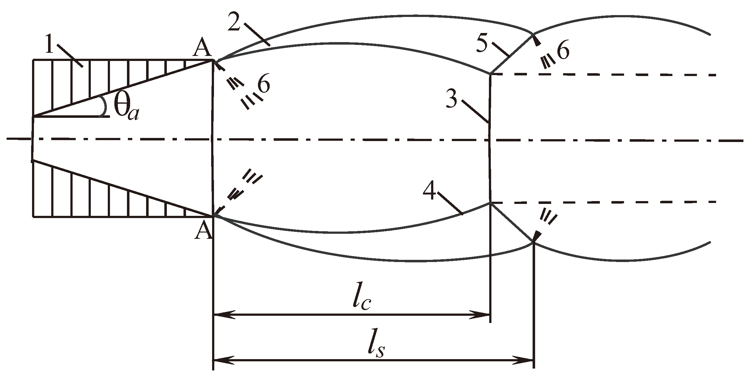
Figure 1. Structure of underexpanded supersonic jet.
Fluids 09 00148 g001
Figure 2. Definition of reference surface.
Fluids 09 00148 g002
Figure 3. Definition of Kirchhoff surface.
Fluids 09 00148 g003
Figure 4. Discretization of a cylindrical control surface.
Fluids 09 00148 g004
Figure 5. Interpolation of required functions at a delayed time moment.
Fluids 09 00148 g005
Figure 6. Computational domain and nozzle geometry.
Fluids 09 00148 g006
Figure 7. Grid (a) and grid near the nozzle outlet (b).
Fluids 09 00148 g007
Figure 8. Positions of observation points relative to nozzle outlet.
Fluids 09 00148 g008
Figure 9. Mach number contours for various NPRs.
Fluids 09 00148 g009
Figure 10. Numerical (a) and experimental (b) shadow flow patterns at NPR = 4 .
Fluids 09 00148 g010
Figure 11. Axial distributions of Mach number (a) and turbulent kinetic energy (b) for NPR = 4 .
Fluids 09 00148 g011
Figure 12. Distributions of Mach number at y = 0 (1, •), 31.75 mm (2, ∘) and 38.10 mm (3, □) for NPR = 4 .
Fluids 09 00148 g012
Figure 13. Shape of sonic line for NPR = 2 .
Fluids 09 00148 g013
Figure 14. Dependencies of discharge coefficient (a) and thrust coefficient (b) on nozzle pressure ratio.
Fluids 09 00148 g014
Figure 15. Contours of velocity.
Fluids 09 00148 g015
Figure 16. Contours of pressure in flow (a) and acoustic (b) scales.
Fluids 09 00148 g016
Figure 17. Contours of pressure derivative.
Fluids 09 00148 g017
Figure 18. Third-octave far-field noise spectra (solid lines) in comparison with experiments [45] (symbols) for θ = 32 (1, •), 90 (2, ∘), 118 (3, ■).
Fluids 09 00148 g018
Figure 19. Comparison of calculated (solid line) integral noise radiation patterns with experimental data [45] (symbols ∘) and [46] (symbols •).
Fluids 09 00148 g019
Figure 20. Integral sound pressure levels (solid lines) in angular direction for various Mach numbers.
Fluids 09 00148 g020
Figure 21. Sound pressure level by frequency for φ = 30 (1, •) and 90 (2, ∘).
Fluids 09 00148 g021
Figure 22. Sound pressure level spectra at M = 1.3 .
Fluids 09 00148 g022
Figure 23. Dependence of discrete tone frequency on time. Comparison of experimental data (solid line) with the results of numerical calculations (dashed line).
Fluids 09 00148 g023
Disclaimer/Publisher’s Note: The statements, opinions and data contained in all publications are solely those of the individual author(s) and contributor(s) and not of MDPI and/or the editor(s). MDPI and/or the editor(s) disclaim responsibility for any injury to people or property resulting from any ideas, methods, instructions or products referred to in the content.