
X-ray Computed Tomography Analysis of Historical Woodwind Instruments of the Late Eighteenth Century

 , ,
, ,  ,
,  ,
, 
Abstract
:1. Introduction
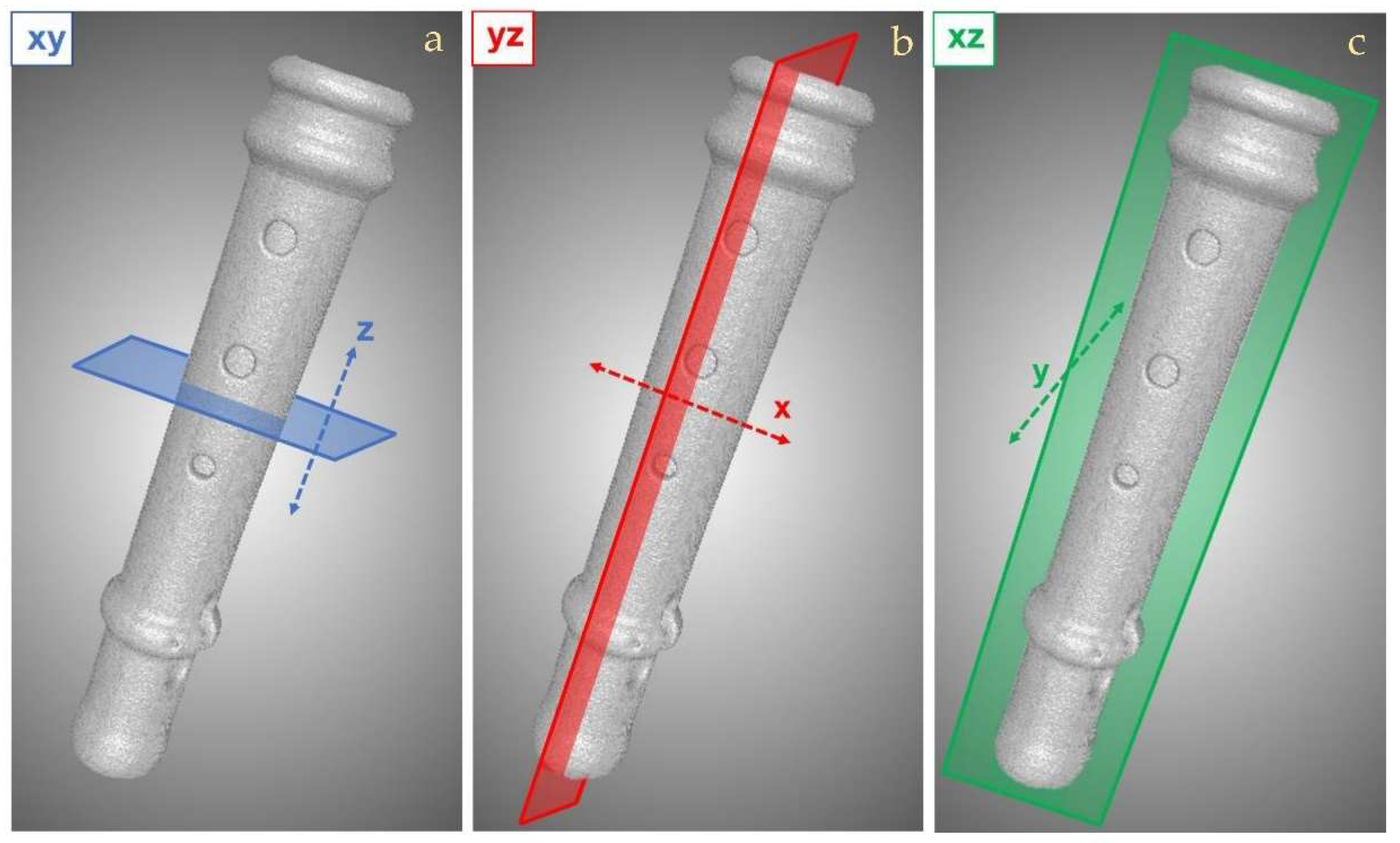
2. Materials and Methods
2.1. Historical Woodwind Instruments
2.2. Experimental
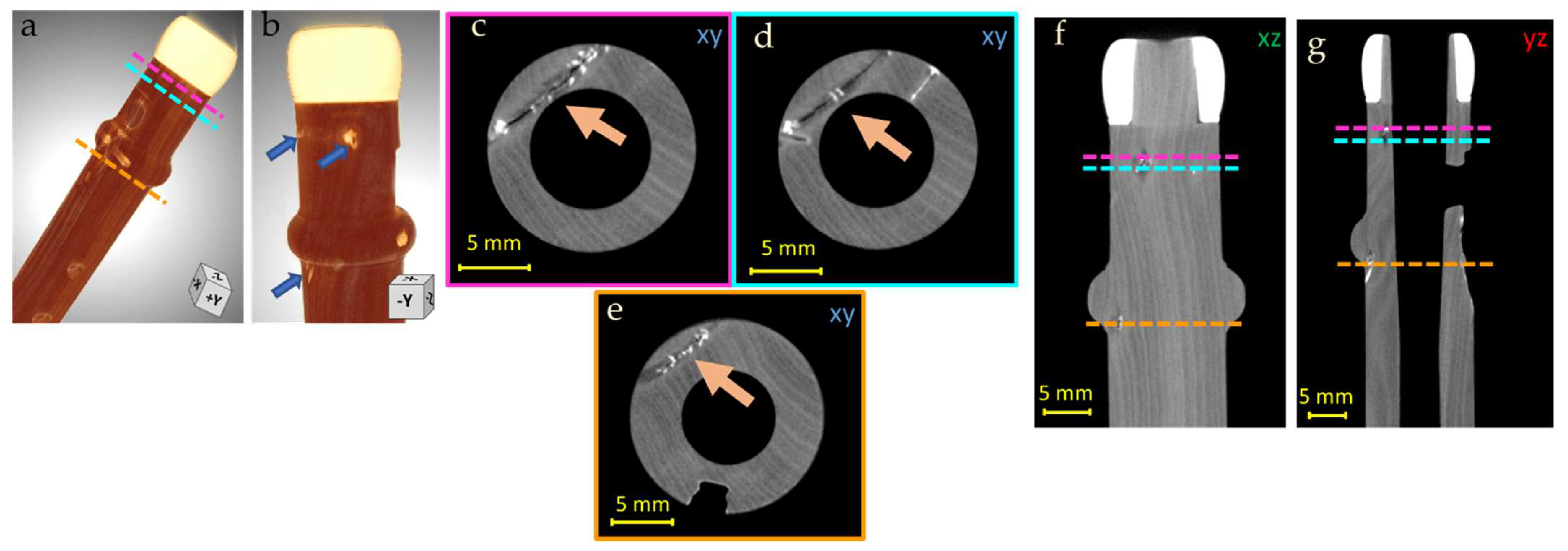
3. Results and Discussion
- fractures,
- cracks associated with wood knots,
- holes and manufacturing defects in the bore,
- areas with higher radiopacity (high density material inclusions),
- fracture repairs,
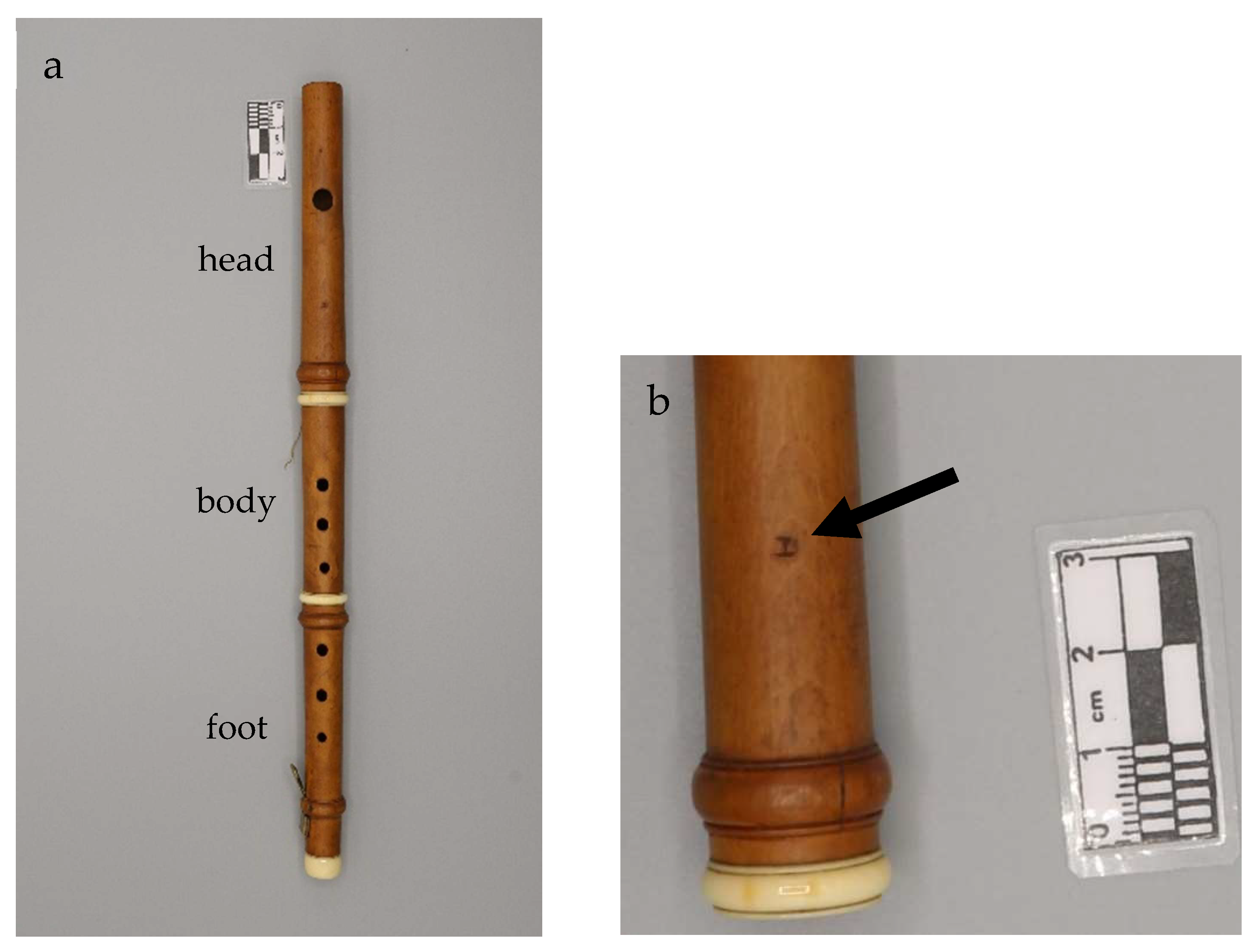
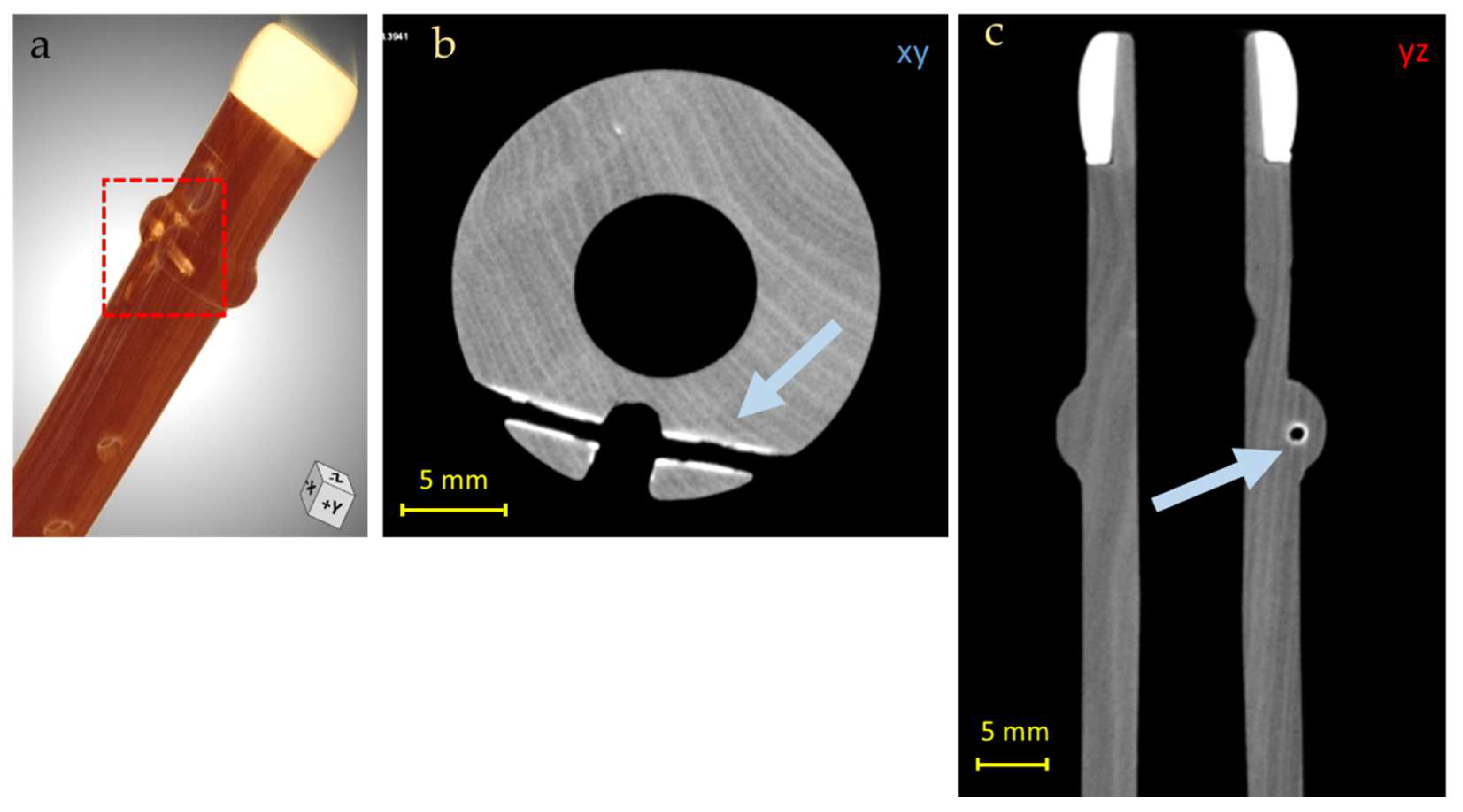
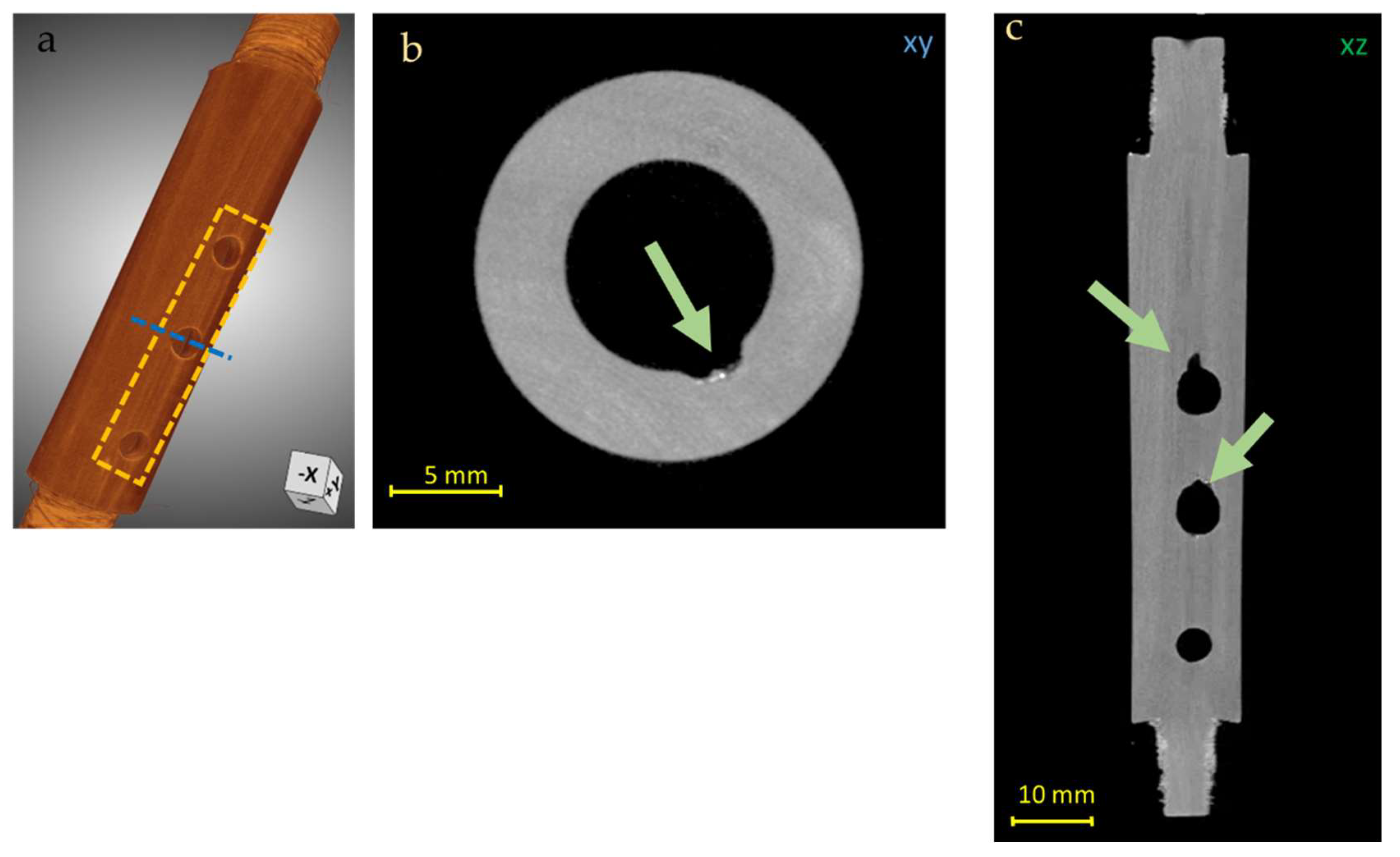
3.1. Piccolo Flute
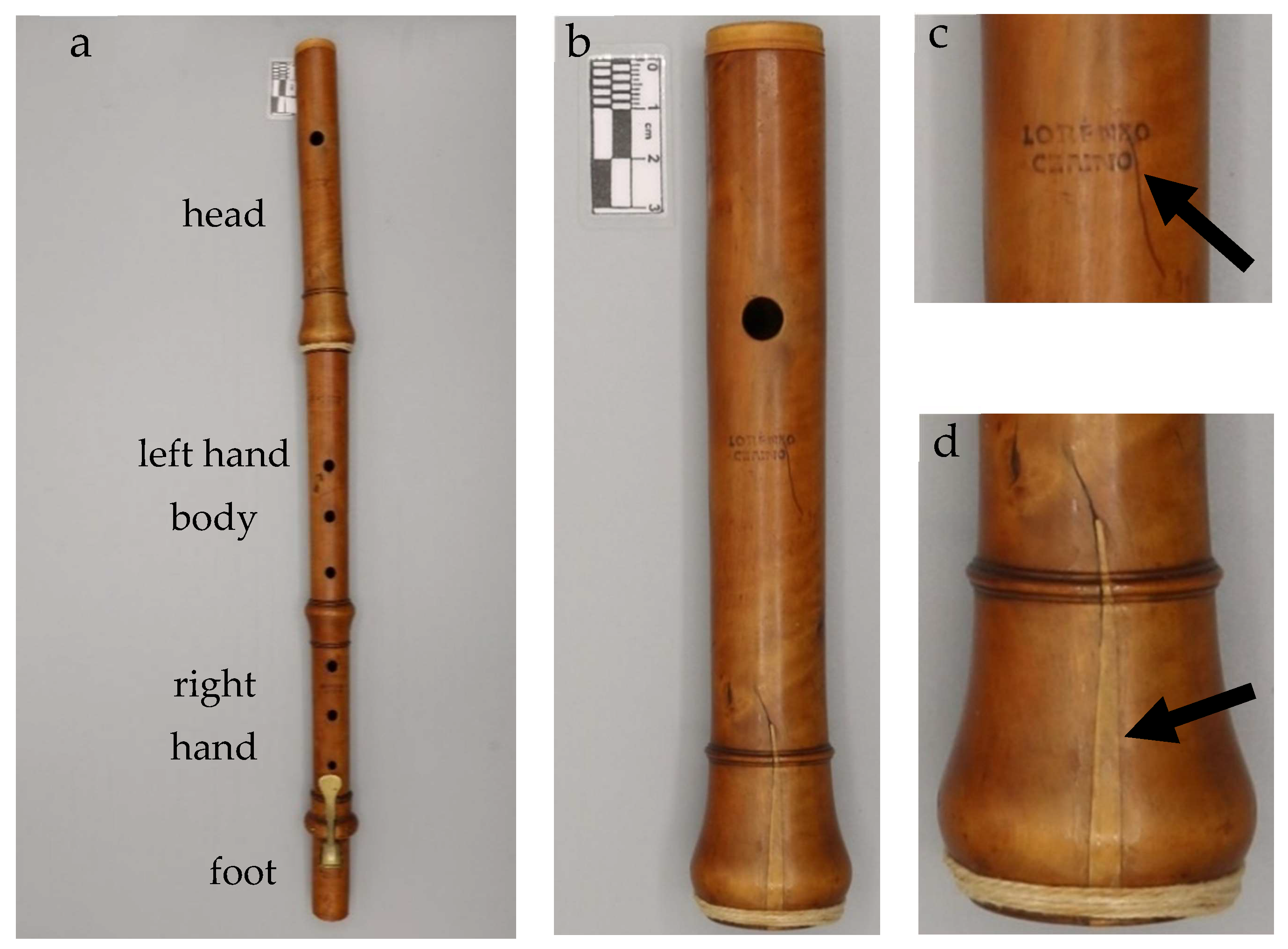
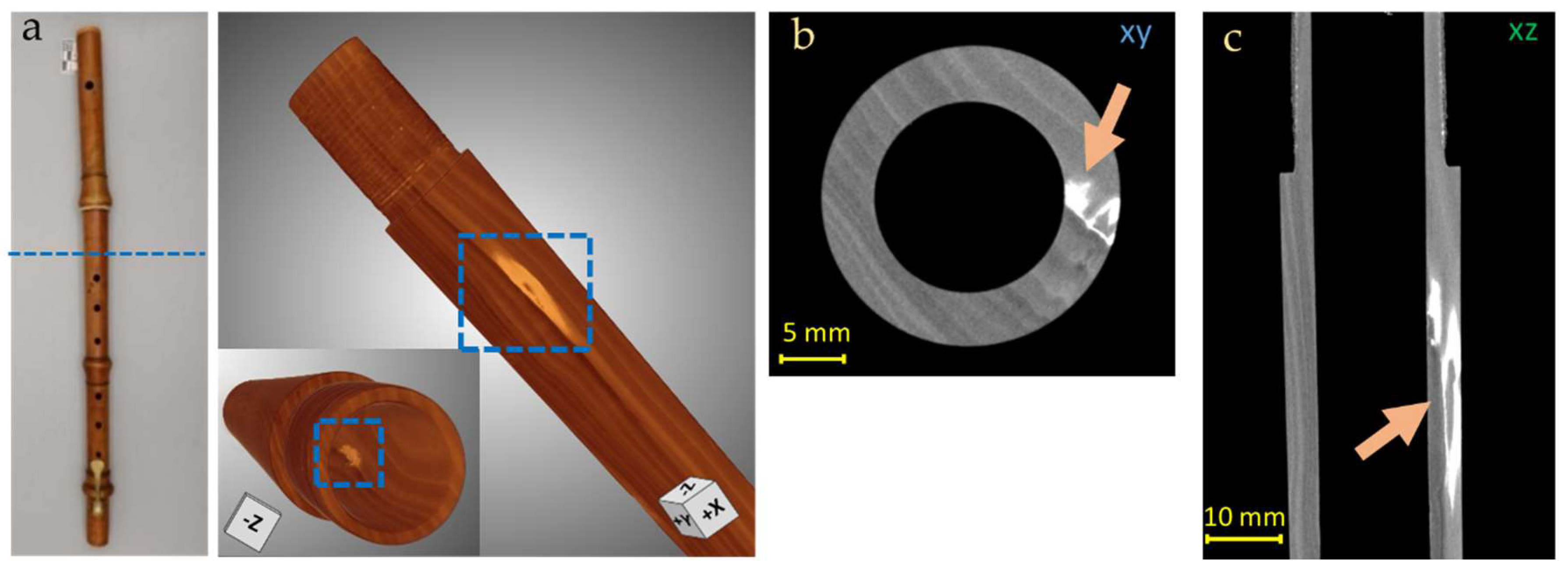
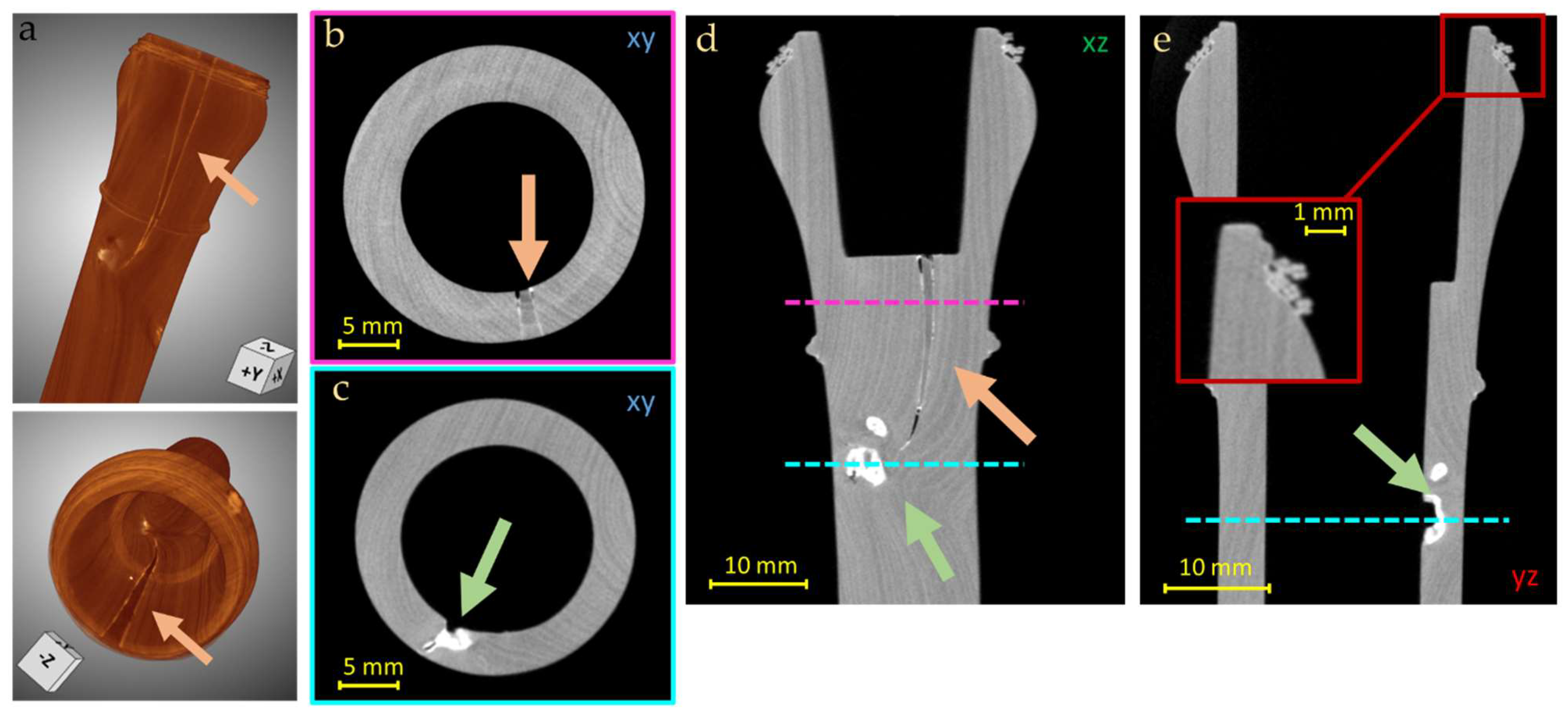
3.2. Transverse Flute
4. Conclusions
Author Contributions
Funding
Institutional Review Board Statement
Informed Consent Statement
Data Availability Statement
Acknowledgments
Conflicts of Interest
References
- Lehmann, E.H.; Lämmlein, S.; Mannes, D. Neutron imaging as tool for investigations on historical musical instruments. J. Archaeol. Sci. Rep. 2018, 20, 239–243. [Google Scholar] [CrossRef]
- Howe, R.; Shahbazmohamadi, S.; Bass, R.; Singh, P. Digital evaluation and replication of period wind instruments: The role of micro-computed tomography and additive manufacturing. Early Music. 2014, 42, 529–536. [Google Scholar] [CrossRef]
- Morigi, M.P.; Casali, F.; Bettuzzi, M.; Brancaccio, R. Three-dimensional X-ray Computed Tomography: A new diagnostic tool for artistic and Cultural Heritage. Disegnarecon 2010, 3, 27–42. [Google Scholar]
- Casali, F. X-ray and Neutron Digital Radiography and Computed Tomography for Cultural Heritage. In Physical Techniques in the Study of Art, Archaeology and Cultural Heritage; Bradley, D., Creagh, D., Eds.; Elsevier: Amsterdam, The Netherlands, 2006; pp. 41–123. [Google Scholar]
- Re, A.; Lo Giudice, A.; Nervo, M.; Buscaglia, P.; Luciani, P.; Borla, M.; Greco, C. The importance of tomography studying wooden artefacts: A comparison with radiography in the case of a coffin lid from ancient Egypt. Int. J. Conserv. Sci. 2016, 7, 935–944. [Google Scholar]
- Re, A.; Corsi, J.; Demmelbauer, M.; Martini, M.; Mila, G.; Ricci, C. X-ray tomography of a soil block: A useful tool for the restoration of archaeological finds. Herit. Sci. 2015, 3, 4. [Google Scholar] [CrossRef]
- Germanisches National Museum. Musices. Available online: https://www.gnm.de/en/research/research-projects/musices/ (accessed on 15 July 2021).
- Festa, G.; Tardino, G.; Pontecorvo, L.; Mannes, D.C.; Senesi, R.; Gorini, G.; Andreani, C. Neutrons and music: Imaging investigation of ancient wind musical instruments. Nucl. Instrum. Methods Phys. Res. B 2014, 336, 63–69. [Google Scholar] [CrossRef]
- Van den Bulcke, J.; Van Loo, D.; Dierick, M.; Masschaele, B.; Van Hoorebeke, L.; Van Acker, J. Nondestructive research on wooden musical instruments: From macro- to microscale imaging with lab–based X–ray CT system. J. Cult. Herit. 2017, 27S, S78–S87. [Google Scholar] [CrossRef]
- Topham, J.; McCormick, D. A dendrochronological investigation of stringed instruments of the Cremonese school (1666–1757) including ‘The Messiah’ violin attributed to Antonio Stradivari. J. Arch. Sci. 2000, 27, 183–192. [Google Scholar] [CrossRef]
- Rigon, L.; Longo, L.; Bergamaschi, A. Synchrotron-radiation microtomography for the non-destructive structural evaluation of bowed stringed instruments Musical instruments at SYRMEP. e-PS 2010, 7, 71–77. [Google Scholar]
- Fiocco, G.; Rovetta, T.; Malagodi, M.; Licchelli, M.; Gulmini, M.; Lanzafame, G.; Zanini, F.; Lo Giudice, A.; Re, A. Synchrotron radiation micro-computed tomography for the investigation of finishing treatments in historical bowed string instruments: Issues and perspectives. Eur. Phys. J. Plus 2018, 133, 525. [Google Scholar] [CrossRef]
- Sodini, N.; Dreossi, D.; Chen, R.; Fioravanti, M.; Giordano, A.; Herrestal, P.; Rigon, L.; Zanini, F. Non-invasive microstructural analysis of bowed stringed instruments with synchrotron radiation X-ray microtomography. J. Cult. Herit. 2012, 13S, 44–49. [Google Scholar] [CrossRef]
- Pérez, M.A.; Marconi, E. Wooden Musical Instruments Diferent Forms of Knowledge. In Book of End of WoodMusICK COST Action FP1302; Cité de la Musique—Philharmonie de Paris: Paris, France, 2018. [Google Scholar]
- Coltman, J.W. Effect of Material on Flute Tone Quality. J. Acoust. Soc. Am. 1971, 49, 520–523. [Google Scholar] [CrossRef]
- Boutin, H.; Le Conte, S.; Vaiedelich, S.; Fabre, B.; Le Carrou, J.L. Acoustic dissipation in wooden pipes of different species used in wind instrument making: An experimental study. J. Acoust. Soc. Am. 2017, 141, 2840. [Google Scholar] [CrossRef] [PubMed] [Green Version]
- Rosin, M. I Quaderni del CSSM, Lineamenti di storia Delle Notazioni Musicali in Occidente. 2005. Available online: http://www.iltamnsy.net/cssm/Quaderni%20CSSM%201.pdf (accessed on 9 May 2022).
- Available online: https://mimo-international.com/MIMO/ (accessed on 27 October 2021).
- Odling, F.; Girodo, L. Documenti sulla costruzione degli strumenti a fiato a Torino fra XVII e XVIII secolo. In Liuteria Musica e Cultura, 1999–2000; LIM Editor: Toscany, Italy, 2001; pp. 25–42. [Google Scholar]
- Vigorelli, L.; Croce, E.; Angelici, D.; Navone, R.; Grassini, S.; Guidorzi, L.; Re, A.; Lo Giudice, A. X-ray Micro-Tomography as a Method to Distinguish and Characterize Natural and Cultivated Pearls. Condens. Matter 2021, 6, 51. [Google Scholar] [CrossRef]
- Vigorelli, L.; Re, A.; Guidorzi, L.; Cavaleri, T.; Buscaglia, P.; Nervo, M.; Facchetti, F.; Borla, M.; Grassini, S.; Lo Giudice, A. X-ray imaging investigation on the gilding technique of an Ancient Egyptian taweret wooden statuette. J. Imaging 2021, 7, 229. [Google Scholar] [CrossRef] [PubMed]
- Vigorelli, L.; Re, A.; Buscaglia, P.; Manfredda, N.; Nervo, M.; Cavaleri, T.; Del Vesco, P.; Borla, M.; Grassini, S.; Guidorzi, L.; et al. Comparison of two ancient Egyptian Middle Kingdom statuettes from the Museo Egizio of Torino through computed tomographic measurements. J. Archaeol. Sci. Rep. 2022, 44, 103518. [Google Scholar] [CrossRef]
- Jackson, D.F.; Hawkes, D.J. X-ray attenuation coefficients of elements and mixtures. Phys. Rep. 1981, 70, 169–233. [Google Scholar] [CrossRef]
- Kak, A.C.; Slaney, M. Malcolm Slaney, Principles of Computerized Tomographic Imaging; IEEE Press: New York, NY, USA, 1999. [Google Scholar]
- ORS. Dragonfly Software, version 2022.1.; Object Research Systems, Inc.: Montreal, QC, Canada, 2018; Available online: http://www.theobjects.com/dragonfly (accessed on 8 September 2021).
- Barclay, R.L. The Conservation of Musical Instruments. Mus. Int. 1996, 48, 9–14. [Google Scholar] [CrossRef]


| Shad-O-Box 6K HS Flat Panel Detector | Hamamatsu Microfocus L8121-03 X-ray Source | ||
|---|---|---|---|
| Pixel number | 2304 × 2940 | Target | Tungsten |
| Active area | 11.4 × 14.6 cm2 | Voltage | 40–150 kV |
| Pixel size | 49.5 μm | Max Current | 500 μA |
| A/D converter | 14 bit | Max Power | 75 W |
| Energy range | 15–225 keV | Focal Spot | Small ≈ 7 μm; Medium ≈ 20 μm; Large ≈ 50 μm |
| Scintillator | CsI | Beam angle | 43° |
| Data transfer | Gigabit Ethernet | Exit window | Be, 200 μm |
| Piccolo Flute | Transverse Flute | |
|---|---|---|
| Dimension of the object | Length 339 mm | Length 427 mm |
| Diameter~22 mm | Diameter~34 mm | |
| Material | Boxwood, ivory | Boxwood |
| X-ray tube voltage | 90 kV | |
| X-ray tube current | 500 µA | |
| X-ray filter (a) | Al (2 mm) | |
| Focal spot size | L (50 µm) | |
| Source-Detector Distance (SDD) | 1400 mm | |
| Source-Object Distance (SOD) | 1300 mm | |
| Object-Detector Distance (ODD) | 100 mm | |
| Magnification | (1.08 ± 0.01)× | |
| Angular step | 0.25° | |
| Integration time | 4 s | |
| Number of projections | 1440 | |
| Scan phases (portions) (b) | 1 | 3 |
| Total acquisition time (c) | 2 h 22 min | 7 h 6 min |
| Reconstruct voxel size | (46 ± 2) μm | |
| Dimension of one CT scan | 18.6 Gb | |
Publisher’s Note: MDPI stays neutral with regard to jurisdictional claims in published maps and institutional affiliations. |
© 2022 by the authors. Licensee MDPI, Basel, Switzerland. This article is an open access article distributed under the terms and conditions of the Creative Commons Attribution (CC BY) license (https://creativecommons.org/licenses/by/4.0/).
Share and Cite
Tansella, F.; Vigorelli, L.; Ricchiardi, G.; Re, A.; Bonizzoni, L.; Grassini, S.; Staropoli, M.; Lo Giudice, A. X-ray Computed Tomography Analysis of Historical Woodwind Instruments of the Late Eighteenth Century. J. Imaging 2022, 8, 260. https://doi.org/10.3390/jimaging8100260
Tansella F, Vigorelli L, Ricchiardi G, Re A, Bonizzoni L, Grassini S, Staropoli M, Lo Giudice A. X-ray Computed Tomography Analysis of Historical Woodwind Instruments of the Late Eighteenth Century. Journal of Imaging. 2022; 8(10):260. https://doi.org/10.3390/jimaging8100260
Chicago/Turabian StyleTansella, Francesca, Luisa Vigorelli, Gabriele Ricchiardi, Alessandro Re, Letizia Bonizzoni, Sabrina Grassini, Manuel Staropoli, and Alessandro Lo Giudice. 2022. "X-ray Computed Tomography Analysis of Historical Woodwind Instruments of the Late Eighteenth Century" Journal of Imaging 8, no. 10: 260. https://doi.org/10.3390/jimaging8100260
APA StyleTansella, F., Vigorelli, L., Ricchiardi, G., Re, A., Bonizzoni, L., Grassini, S., Staropoli, M., & Lo Giudice, A. (2022). X-ray Computed Tomography Analysis of Historical Woodwind Instruments of the Late Eighteenth Century. Journal of Imaging, 8(10), 260. https://doi.org/10.3390/jimaging8100260