Abstract
Tractor overturning accidents are a prominent safety concern in the field of agriculture. Many studies have been conducted to prevent tractor overturning accidents. Rollover protective structures and seat belts currently installed on tractors cannot prevent them from overturning. The posture of a tractor was controlled by installing individual actuators. The overturning angles of the tractor equipped with an actuator were compared with those of a tractor with no actuator. For the overturning angles in all directions of the tractor, it rotated 15° from 0° to 345°, and the actuator height suitable for the tractor posture was controlled by establishing an equation according to the tractor posture. Consequently, posture control using actuators was noticeably improved. This study proposes that tractors operating on irregular and sloping terrain be equipped with individual actuators. These results prevent tractor rollover accidents and improve safety and driving stability.
1. Introduction
Compared to automobiles, tractors are often operated in difficult driving conditions, such as uneven terrain or slopes, thus having a relatively high risk of rollover accidents [1]. As per statistics, rollover accidents not only account for a large portion of agricultural machinery accidents but also cause serious injuries and driver deaths [2,3,4]. According to the U.S. Bureau of Labor Statistics [5], rollover accidents account for the highest percentage of accidents in the agricultural sector. In Portugal, tractors account for 79.0% of all fatal accidents due to agricultural machinery: tractor rollovers account for 38.6% of deaths, followed by 19.3% of deaths caused by falls [6]. In Italy, out of 817 fatalities in the agricultural sector between 2002 and 2012, 357 were due to tractor accidents, of which 205 were due to rollovers, accounting for 57.4% of the overall fatalities. Furthermore, 71.7% of tractor accidents involved tractors not equipped with rollover protective structures (ROPS) [7]. In the Konya province of Türkiye, 37.2% of tractor accident deaths were due to the overturning of tractors [8]. Therefore, rollover accidents continue to be recorded in the agricultural sector, further emphasizing the importance of safety devices for tractor rollover accidents.
ROPS and seat belts are common conventional safety devices installed on tractors [9,10,11]. These conventional devices have been studied for performance improvement and utilization [12,13,14,15,16]. Conventional safety devices play an important role in protecting the driver, but their shape and installation method can lead to the risk of rollover accidents [17,18]. Ayers et al. [19] found that the risk of a continuous rollover accident increased as the center of gravity (CoG) of the tractor increased in height. Therefore, the proper setting of ROPS height along with a CoG height is necessary to prevent rollover accidents. Franceschetti et al. [20] calculated the mass and CoG according to the shape of the ROPS and confirmed that the risk of rollover accidents increases depending on the shape of the ROPS. The shape of the ROPS plays an important role in protecting the driver. But, depending on its shape and installation method, ROPS can instead increase the risk of rollover accidents. Seat belts also play an important role in increasing driver safety. Although studies have been actively conducted to evaluate and improve these conventional safety devices, they only protect the life of the driver and do not prevent rollover accidents [21]. Therefore, rather than protecting the driver’s life after a tractor overturning accident, a method to prevent an overturning accident is needed.
Various studies have proposed methods to prevent tractor rollover accidents. Kise and Zhang [22] proposed a method that uses a sensor-in-the-loop to detect and analyze tractor attitude and motion to predict the risk of rollover accidents. Thus far, they conducted tests using a stereovision camera to identify the terrain and predict tractor attitude and motion, showing consistent accuracy and proving that it can be applied as a device to prevent rollovers in practice. Thus, it has focused on adding devices and systems. In the 2020s, studies that modified the traditional structure of a tractor emerged. Qin et al. [23] proposed a method to prevent rollovers by turning the wheels of a tractor downward on a ramp using conventional steering and flywheels. Moreover, the independent link suspension (ILS) system, a recent development that improves tractor drivability and safety, uses independently operated links at each wheel on the front axle to drive the vehicle stably on uneven ground. However, the ILS has limited ability to control the movement of the CoG of the tractor because it is mounted only on the front wheels. Therefore, the current system is not sufficient to prevent rollover accidents. However, it was determined that a greater effect could be achieved by adopting a method that controls the front and rear wheels. Therefore, the subsequent technological advancement involved controlling the tractor attitude through actuators by installing an active suspension on each of the front and rear wheels, rather than solely on the front wheels. This technology, widely employed in the automotive field, enhances stability by managing vehicle attitude through individual active suspensions. Ni and He [24] developed a rollover prevention system using actuators and evaluated its performance to prevent a vehicle from rolling over. The rollover was prevented by moving the CoG using vehicle attitude control. These experimental results and technological advances are expected to have a positive impact on improving driving safety and work efficiency of vehicles. Jia et al. [25] developed a prediction model that can minimize unnecessary vehicle movements in complex terrains by using individual active suspensions in addition to the existing suspension system. The prediction model controls the attitude to reduce the tilt and rollover angle of the vehicle. Both studies dramatically reduced the vehicle vibration and significantly improved the attitude stability. Based on these studies, it is expected that equipping tractors with individual active suspension will have a positive impact on increasing stability on uneven ground and reducing vibration, thereby preventing rollover accidents.
Real-world experiments using complex equipment or large equipment, such as a tractor, present significant challenges in terms of cost, time, and manpower [26,27]. Because of these constraints, researchers have recently preferred to first perform analyses using simulations [28,29,30]. Chowdhury et al. [31] analyzed the lateral overturning stability of a radish collector by mathematically calculating the CoG and performed simulations to determine the lateral overturning angle according to the folding position of the radish conveyor belt under different loading conditions. In their simulation-based study, experiments were conducted in a safe manner by controlling various conditions and variables that may be difficult to control in real-world experiments and by analyzing the results. Chowdhury et al. [32] studied the rollover characteristics of an onion transplanter to reduce the risk of rollover. They measured the rollover angle in only one direction. Hence, there is a limitation in knowing the rollover angle in all directions. Kim et al. [33] used simulations to measure the rollover angle of a tractor more accurately in all directions instead of just one direction, which allowed them to analyze the rollover angle at different angles and situations, helping them to develop a method to prevent rollover accidents. By leveraging these simulations, it will be possible to rotate the tractor and derive the rollover angle from all sides.
In this study, an equation was developed that allows the height of the actuator of each wheel to be adjusted according to various environments by installing four separate active suspensions in the tractor. By using this equation to control the attitude of the tractor, it is possible to improve the rollover angle of the tractor and reduce the probability of a rollover accident. This method was verified by simulations, and the results are presented in this paper. This study is significant in that it presents a novel approach to improve tractor safety and prevent rollover accidents.
2. Materials and Methods
2.1. 3D Model of a Tractor for Simulation
A 3D model of a tractor was created using Inventor (Automotive Inventor Professional 2023, Autodesk Inc., San Francisco, CA, USA), and the overturning simulation was conducted using the dynamic simulation program Recurdyn (V2023, Function Bay Inc., Seongnam-si, Republic of Korea). The size of the tractor used in the simulation was 3200 (L) × 2700 (W) × 2800 (H) mm (Table 1). The front wheel used the weight of a size 13.6–24 tire, whereas the rear wheel used the weight of a size 18.4–34 tire.

Table 1.
Specifications of the tractor.
2.2. Simulation Conditions and Method
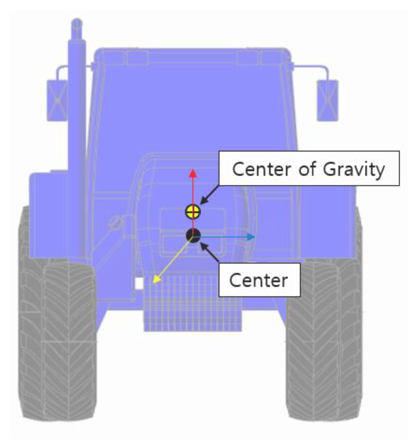
The CoG was determined through a simulation based on the drawings and tractor modeling (Figure 1). The dynamic friction coefficient was 1.2 to prevent the tractor from slipping when the general road-wheel overturned, and the stiffness coefficient and damping coefficient were 105 and 10 (Table 2). This study referred to a lateral rollover simulation paper using an existing dynamics program [34]. The simulation time was set to 30 s, and the number of simulation steps was set to 1000.
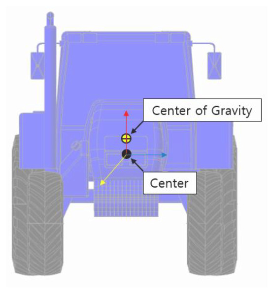
Figure 1.
3D model of a tractor for CoG.
Table 2.
Simulation variable parameters.
The simulation was performed in the following order.
- The tractor was placed on plain ground;
- The ground was tilted in a longitude vector, and the tractor overturned;
- The overturning angle was analyzed when the contact force between the ground and tractor wheels became 0 N.
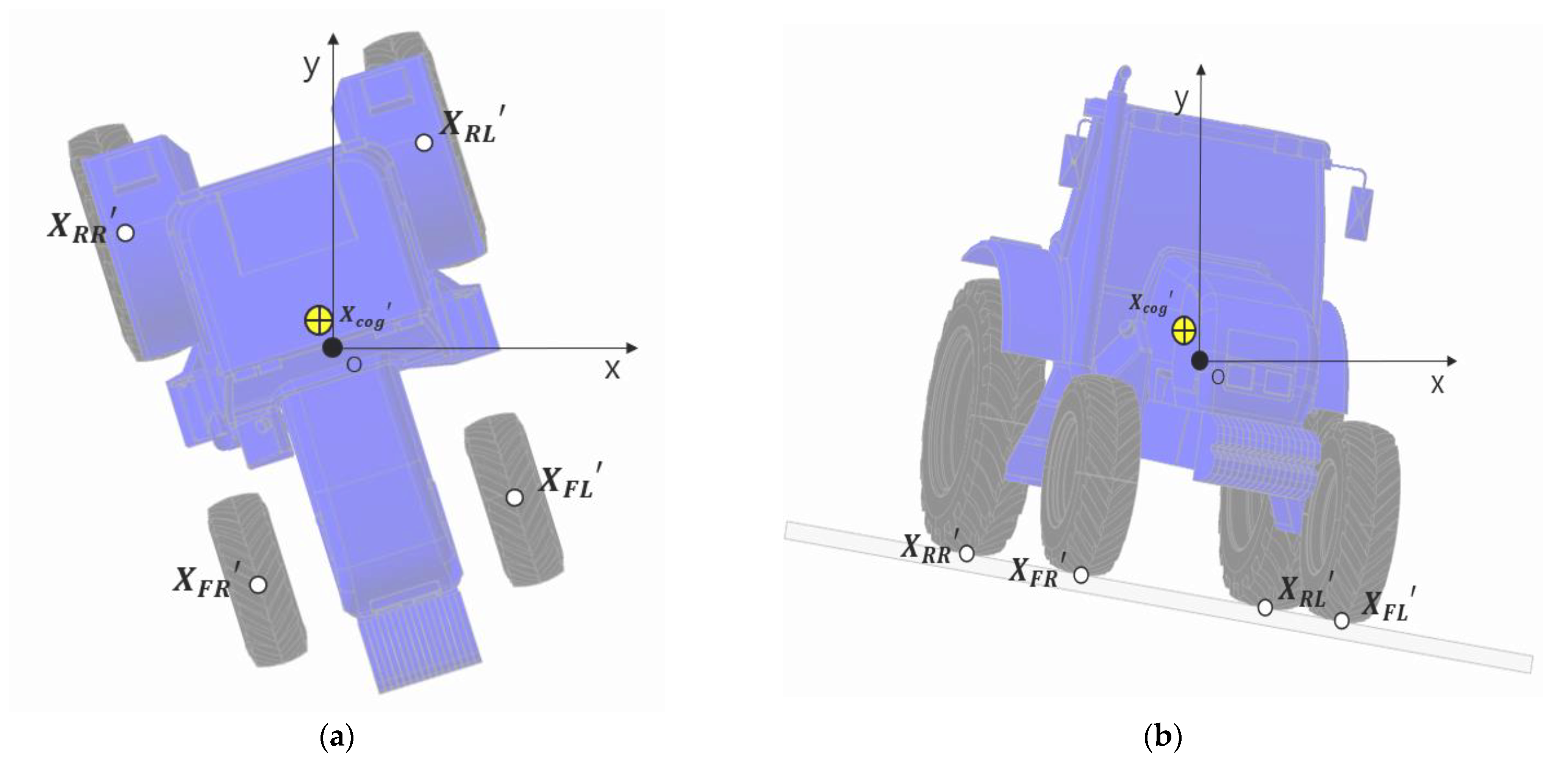
The overturning angle was analyzed by rotating from 0° to 345° with 15° increments in the counterclockwise direction relative to the CoG to analyze the overturning angle according to the entry angle of the tractor on the slope (Figure 2). Here, represents the initial rear right wheel coordinates, represents the initial rear left wheel coordinates, represents the initial front right wheel coordinates, represents the initial front left wheel coordinates, and represents the initial CoG of the tractor coordinates. represents the rear right wheel coordinates after rotation, represents the rear left wheel coordinates after rotation, represents the front right wheel coordinates after rotation, represents the front left wheel coordinates after rotation, and represents the CoG coordinates after rotation.

Figure 2.
Schematic diagram of the rotation of the tractor: (a) Rotated condition; (b) Tilting condition.
In all directions, the overturning angle was referred to as the overturning angle when the contact force between each wheel and the ground became 0 N after rotation.
2.3. Mathematical Model of the Tractor Rollover
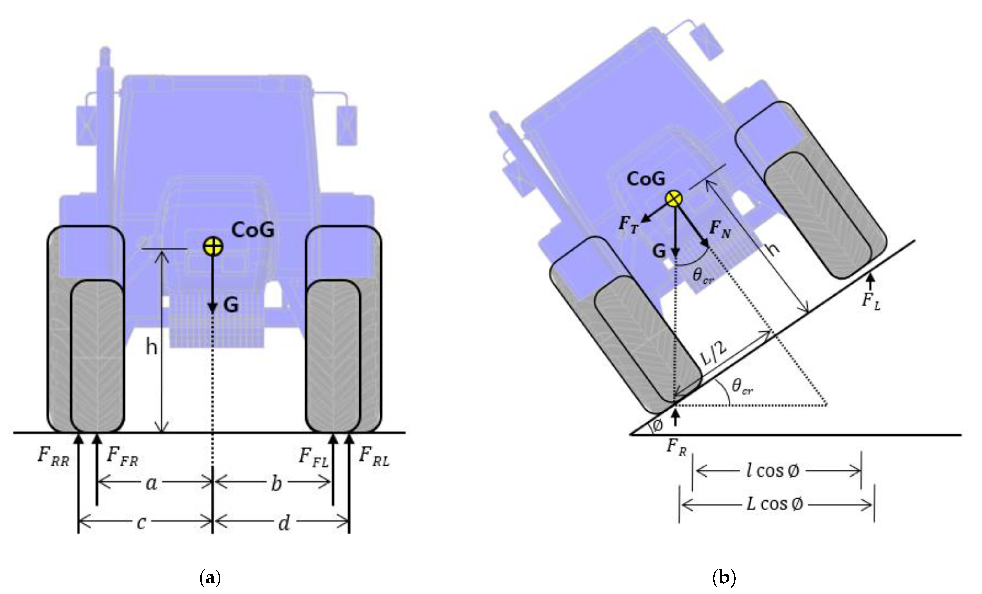
The reason for the tractor overturning is caused by the movement of the CoG. The mass of the tractor is subjected to a force G in the vertical direction to the ground due to gravity acceleration. represents the ground reaction forces and for the tractor’s right front and rear wheels, and represents the ground reaction forces and for the tractor’s left front and rear wheels. h is the vertical distance between the CoG and the ground, is the total distance of the front wheels and , . can be defined as the total distance of the rear wheels by dividing it into and , respectively. and represent the horizontal distance from CoG to the front wheels on the left and right, and and represent the horizontal distance from CoG to the rear wheels on the left and right, respectively (Figure 3). Equations (1)–(3) describe the relationship between the force G and the ground reaction forces acting on the wheels.

Figure 3.
Schematic view of the tractor for mathematic: (a) Static condition; (b) Tilting condition.
When the tractor begins to tilt by an angle of in a static state, the reaction force gradually increases, and decreases gradually. As the tilt progresses, the positions of , , , and change, leading to the generation of the lateral force and vertical force . As the tilting angle increases, there is a point where becomes zero. The angle at that moment can be defined as the critical angle , which can be calculated through the following Equations (4)–(6). In this study, separate expressions for and are needed to calculate rollover not only in the lateral direction but in all directions. If the tilting angle exceeds the critical angle, and the position of the center of gravity (CoG) exceeds the wheelbase, rollover occurs.
2.4. Mathematical Model of the Actuator Height
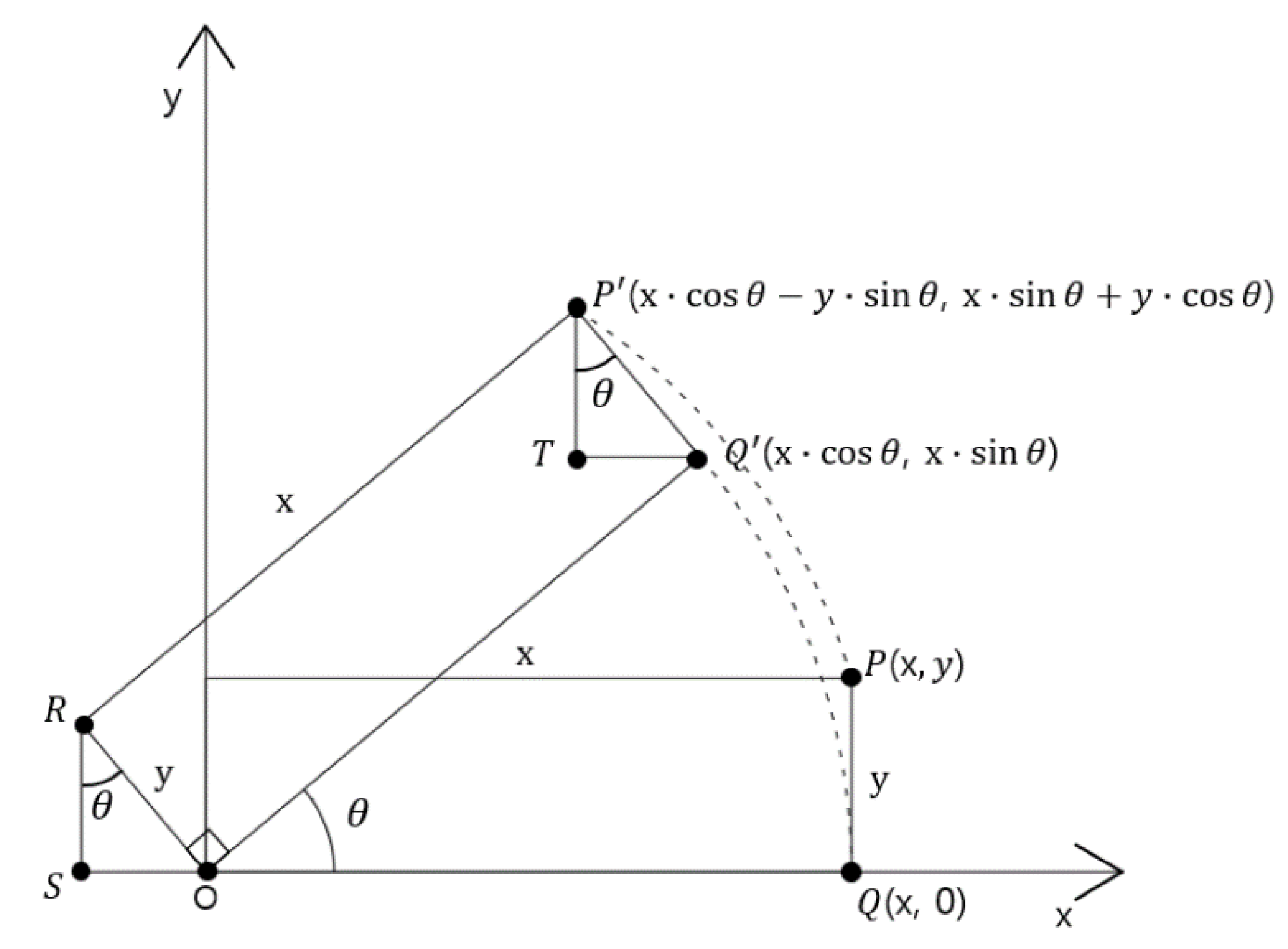
The actuator height was calculated according to the entry angle and tilt angle of the tractor. The coordinates of the wheels of the tractor were represented on a two-dimensional plane and rotated around the midpoint. As the tractor rotates based on the midpoint, the CoG also rotates, so the coordinates of the CoG must continue to be calculated. The coordinates of each wheel at the time of rotation were used by the rotation conversion formula. When the point P (x, y) of the coordinate plane is rotated by the angle θ with respect to the O point (Figure 4), the coordinates of P′ (x′, y′) can be obtained as follows (Equation (1)):

Figure 4.
Proof of the rotational matrix equation.
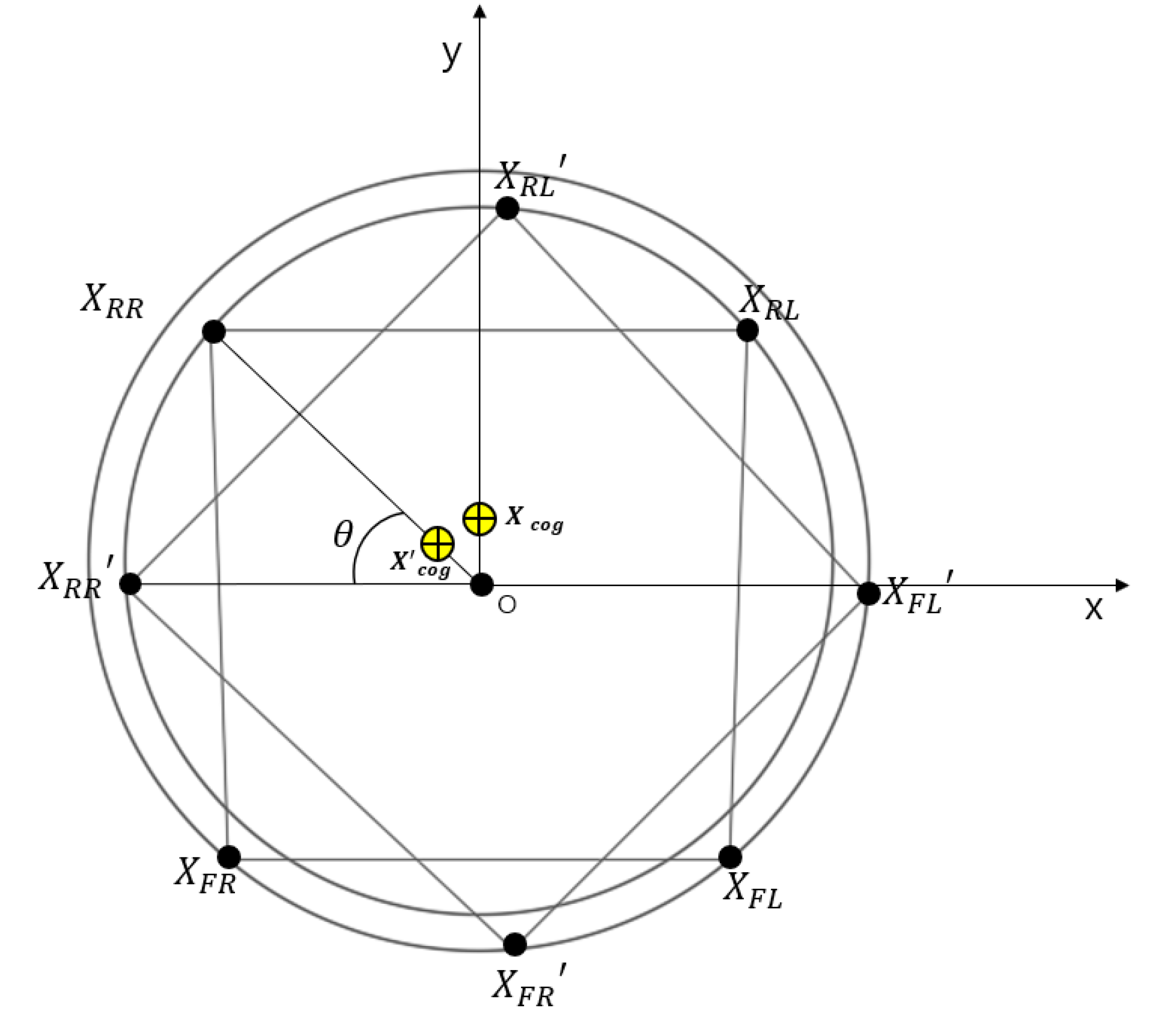
When , , , , and were calculated using Equation (7), , , , , and were corrected first for calculation (Figure 5). The coordinates of the midpoint O were defined as (0, 0), (−1070, 920), (1070, 920), (−936, −1115), and (936, −1115).

Figure 5.
Secondary plane coordinate system for the tractor wheel position.
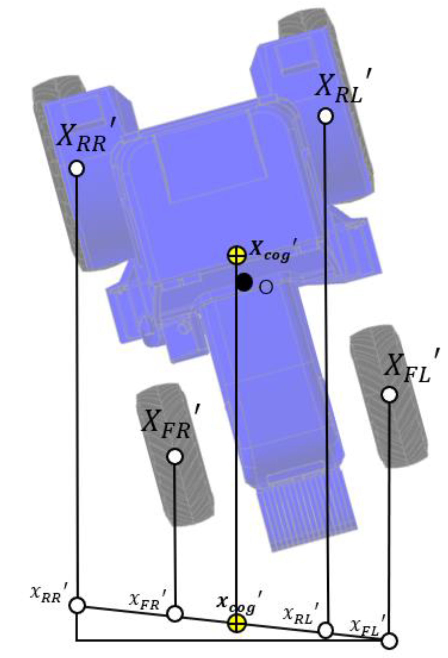
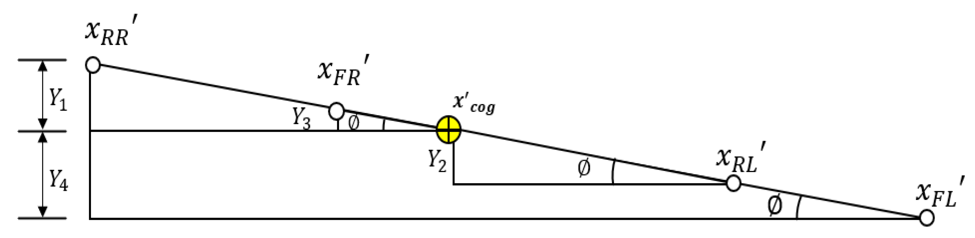
Figure 6 is a projected figure for each wheel actuator height, and Figure 7 is an enlarged figure for calculating the actuator height in Figure 6. indicates the tilting angle of the tractor. After projecting each coordinate, the actuator height according to the tilting angle of the tractor was calculated. Y was the height of the individual actuators and was calculated as the difference in the x coordinates of each coordinate relative to CoG. The maximum length and compression length of the actuator were set to 200 mm so that the wheels of the tractor did not touch the vehicle body. The formula for calculating the height of each actuator is as follows (Equations (8)–(11)):
where is the rear right actuator height, is the rear left actuator height, is the front right actuator height, and is the front left actuator height. represents the x-coordinate projecting each position, and is the tractor tilting angle.

Figure 6.
Projected figure for each wheel actuator height.

Figure 7.
Enlarged picture of the projected figure.
2.5. Hydraulic Actuator Model
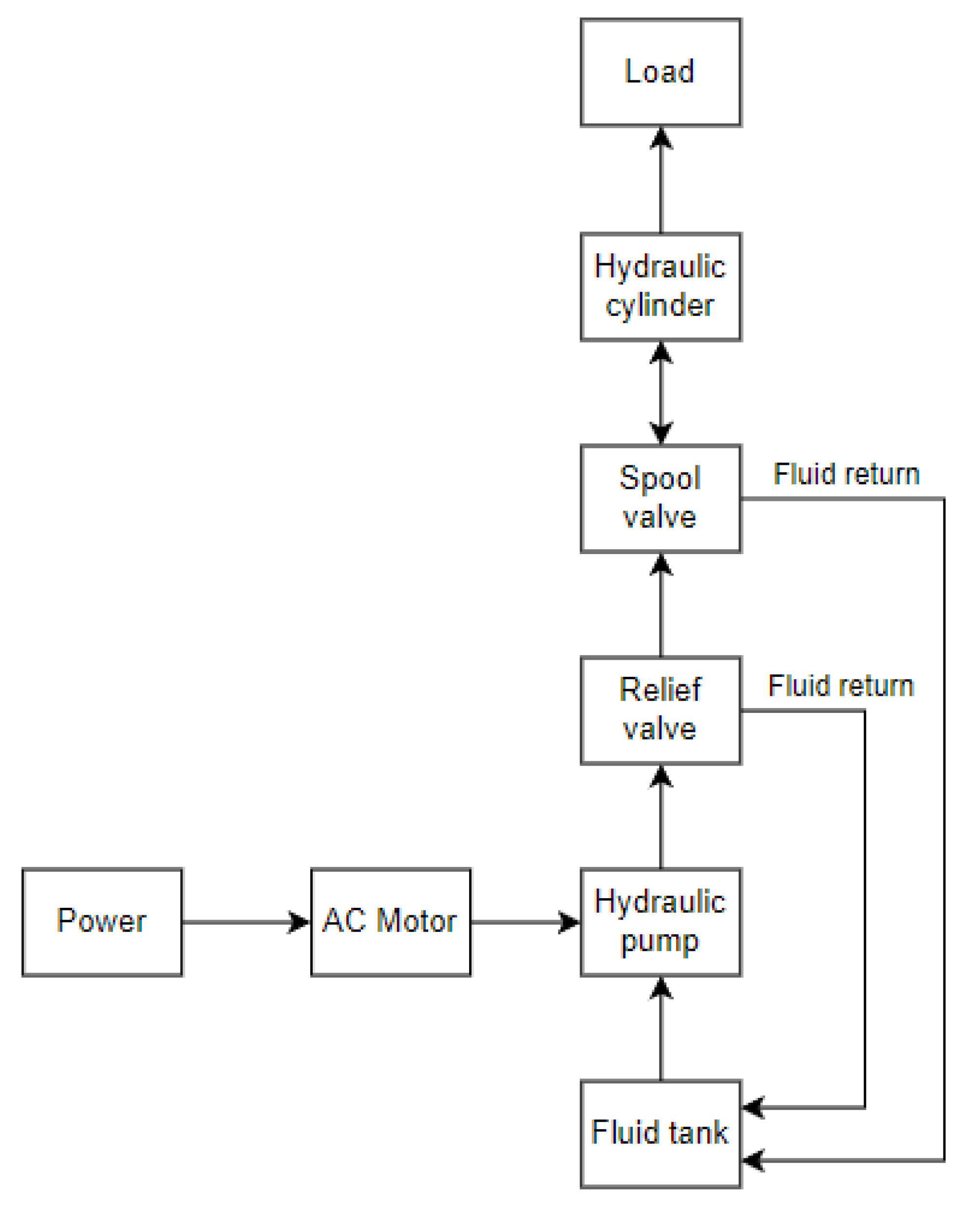
The overall circuit consists of an AC motor, 4-way spool valve, cylinder, hydraulic pump, relief valve, and tank, as shown in Figure 8.
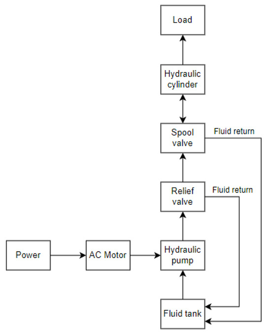
Figure 8.
Schematic diagram of the hydraulic actuator.
Hydraulic actuators were selected based on the maximum load of an individual wheel of a tilted tractor including the weight of the tractor and the actuator, which is 5000 kgf equivalent to 49 kN. The actuating force of the actuator is calculated by Equation (12). The diameter on the piston of the actuator is and the area , and the pressure value P = 12,730 kN/m2. The total length was set to 800 mm, stroke to 400 mm, and speed to 0.5 m/s.
where is the hydraulic force, is the hydraulic pressure, and is the area of the piston.
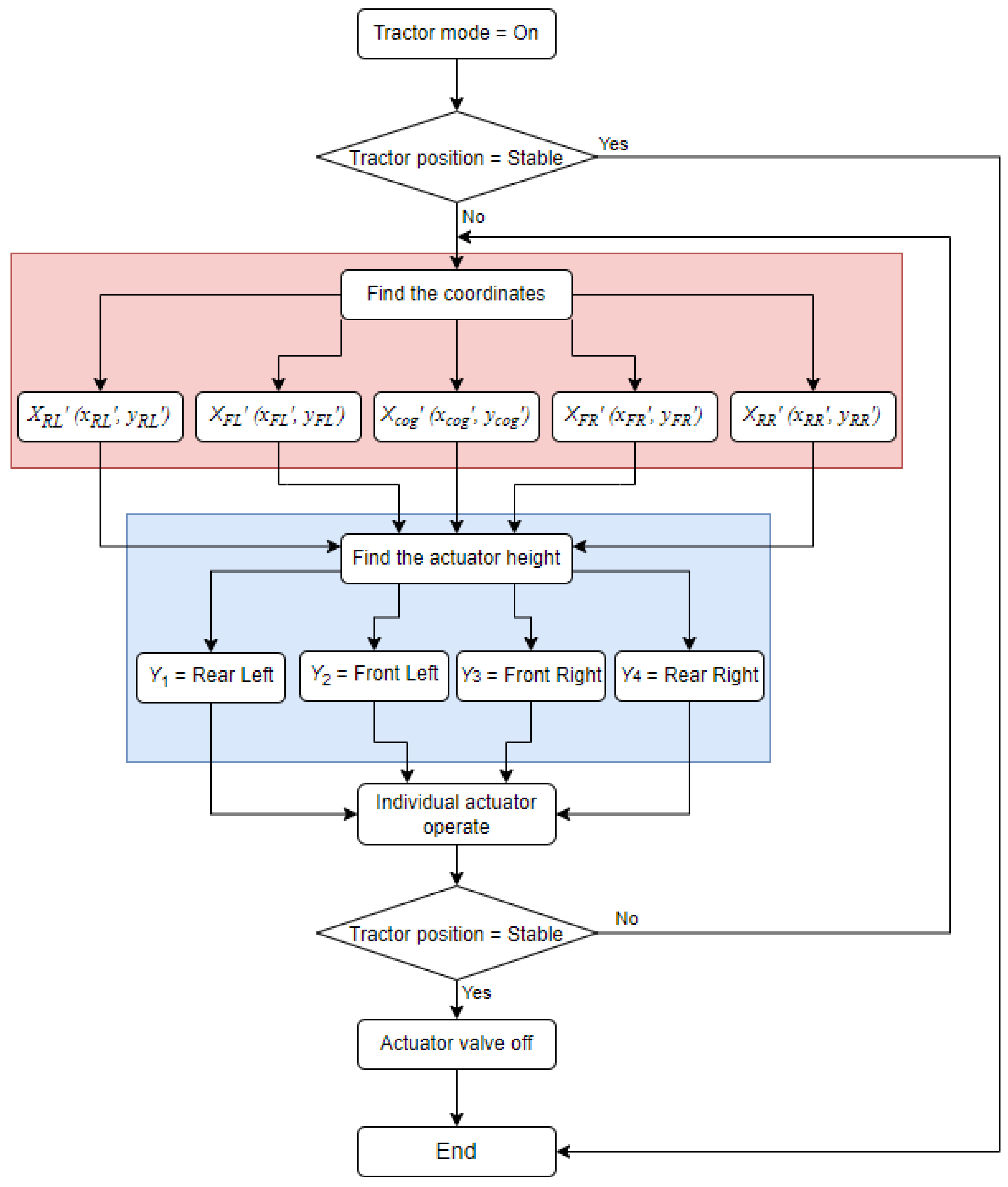
2.6. Development of Tractor Horizontal Attitude Control Logic
The tractor horizontal control was operated when the tractor tilted as shown in Figure 9. The red box indicates the task of finding the coordinates of each wheel. The blue box then represents the task of calculating the height of each wheel using the equation introduced in this paper. Tractor posture aims to maintain its horizontal attitude after the operation of each wheel through feedback control.

Figure 9.
Individual actuator control logic for maintaining the horizontal attitude of the tractor.
3. Results and Discussion
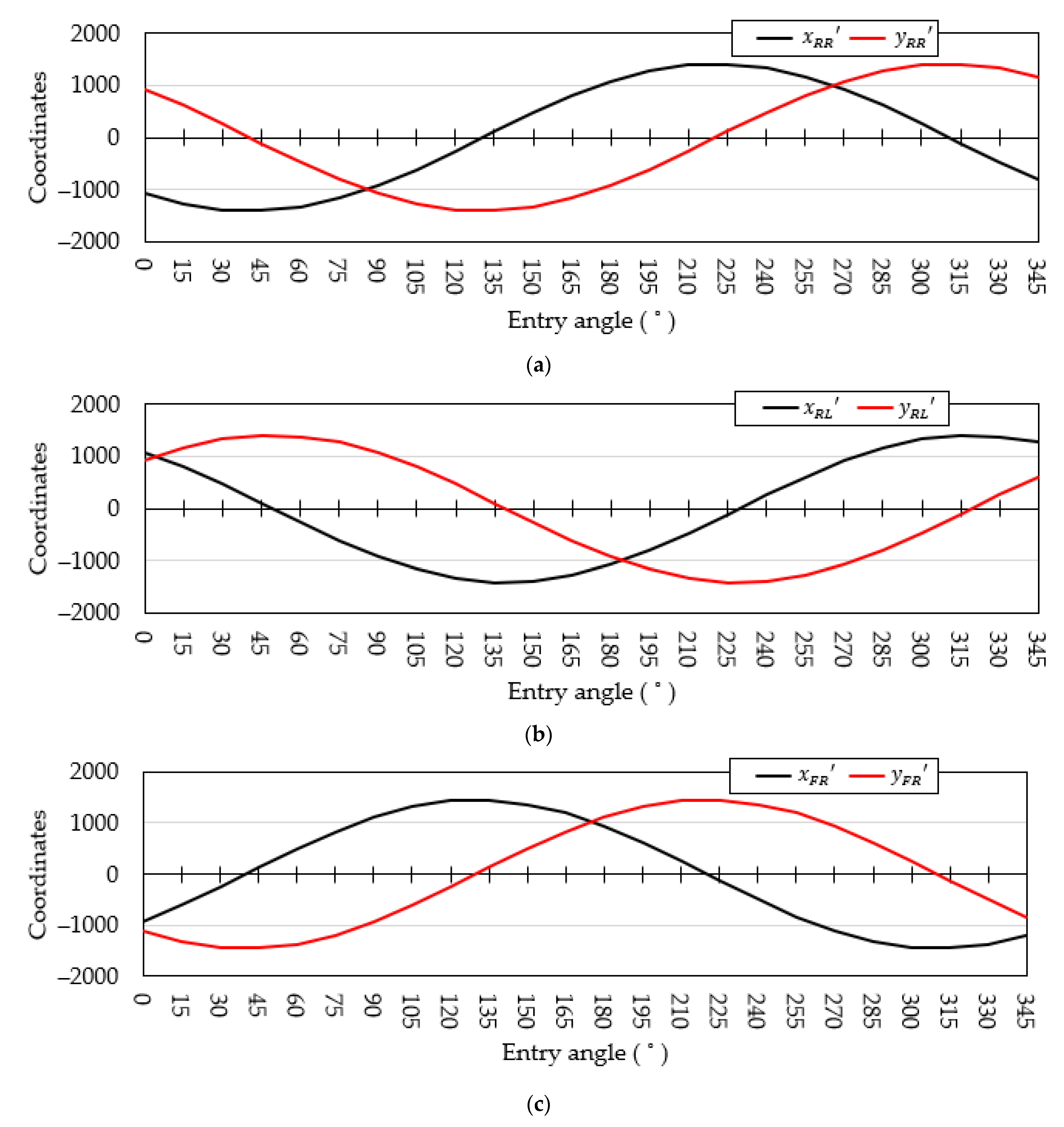
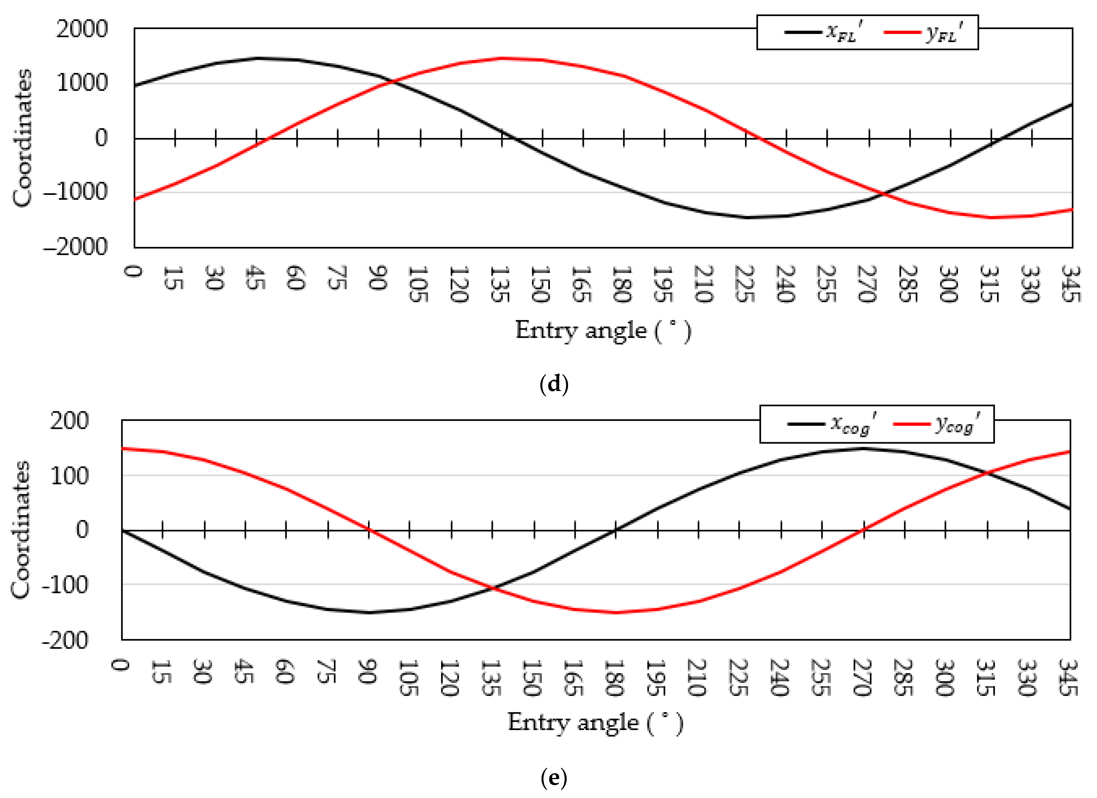
The coordinates of each wheel in a two-dimensional plane were obtained using the rotational matrix equation (Equation (7)), and the x′, y′ coordinates of each wheel that change as the coordinates rotates are as follows (Figure 10). Figure 10a presents the coordinates, the coordinates (−1070, 920) are rotated based on the midpoint O. Figure 10b shows that the coordinates (1070, 920) are rotated based on the midpoint O with the coordinates. Figure 10c indicates that the coordinates (936, 1115) are rotated based on the midpoint O with the coordinates. Figure 10d presents that the coordinates (936, −1115) are rotated based on the midpoint O with the coordinates. Figure 10e shows that the coordinates (0, 150) are rotated based on the midpoint O with the coordinates. All graphs appeared well in the form of a trigonometric function. The trigonometric form was the same because the coordinates of the two wheels and had the same distance from the midpoint. Similarly, the trigonometric form was the same because the coordinates of the two wheels and had the same distance from the midpoint.
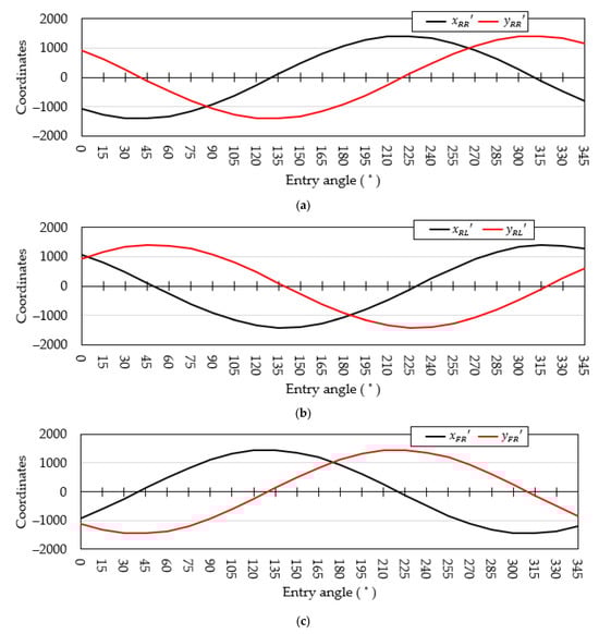
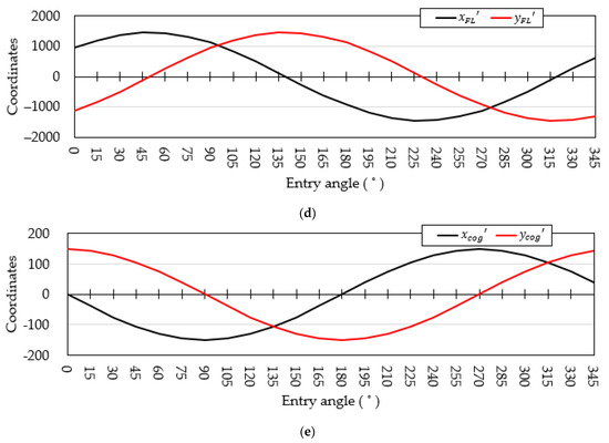
Figure 10.
Each wheel’s x, y coordinates of the secondary plane coordinate systems: (a) , coordinates; (b) , coordinates; (c) , coordinates; (d) , coordinates; and (e) , coordinates.
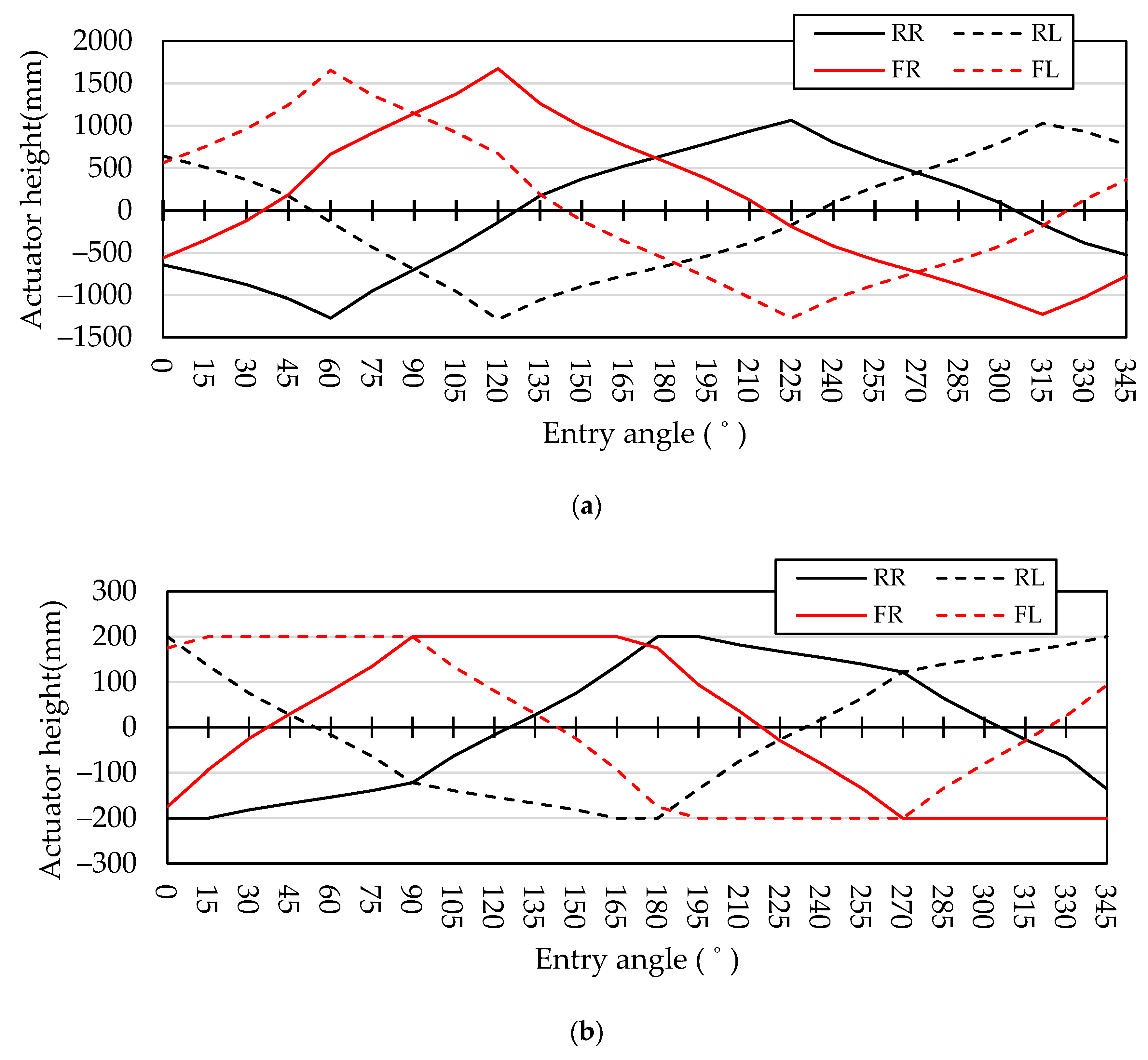
The individual actuator heights were calculated by substituting Equations (8)–(11) through the x-coordinate of each wheel. The calculated actuator heights were as follows (Figure 11). The actuator height represents the adjusted height of wheel for the balance, the “+” sign represents the tension of the actuator, and the “−” sign represents the compression of the actuator. The maximum tensile length of RR was 1064 mm at an entry angle of 225°, the maximum compression length was 1272 mm at an entry angle of 60°, the maximum tensile length of RL was 1026 mm at an entry angle of 315°, the maximum compression length was 1288 mm at an entry angle of 120°, the maximum tensile length of FR was 1147 mm at an entry angle of 90°, the maximum compression length was 1228 mm at an entry angle of 315°, the maximum tensile length of FL was 1656 mm at an entry angle of 60°, and the maximum compression length was 1273 mm at an entry angle of 225° (Figure 11a).
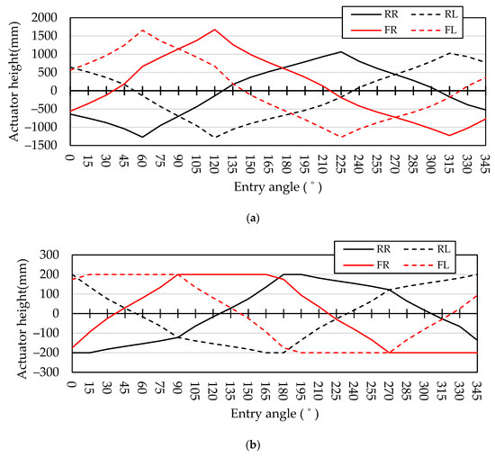
Figure 11.
Actuator height for each wheel entry angle: (a) Nonlimited condition; (b) 200 mm limit condition, where RR is the rear right actuator height, RL is the rear left actuator height, FR is the front right actuator height, and FL is the front left actuator height.
However, if the tension and compression of the actuator are achieved through the actual calculations, the wheel touches the vehicle body, and the operation does not occur. Therefore, the maximum tensile and compression length of the actuator were limited to 200 mm, and the time when one wheel first became 200 mm was applied through the calculation of Equations (3)–(6) and expressed in Figure 11b.
The maximum tensions of RR were 180° and 195°, whereas the maximum compression angles were 0° and 15°. The maximum tensions of RL were 0° and 345°, whereas the maximum compression angles were 165° and 180°. The maximum tensions of FR were 90°, 105°, 120°, 135°, 150°, and 165°, whereas the maximum compression angles were 270°, 285°, 300°, 315°, 330°, and 345°. The maximum tensions of FL were 15°, 30°, 45°, 60°, 75°, and 90°, whereas the maximum compression angles were 195°, 210°, 225°, 240°, 255°, and 270°.
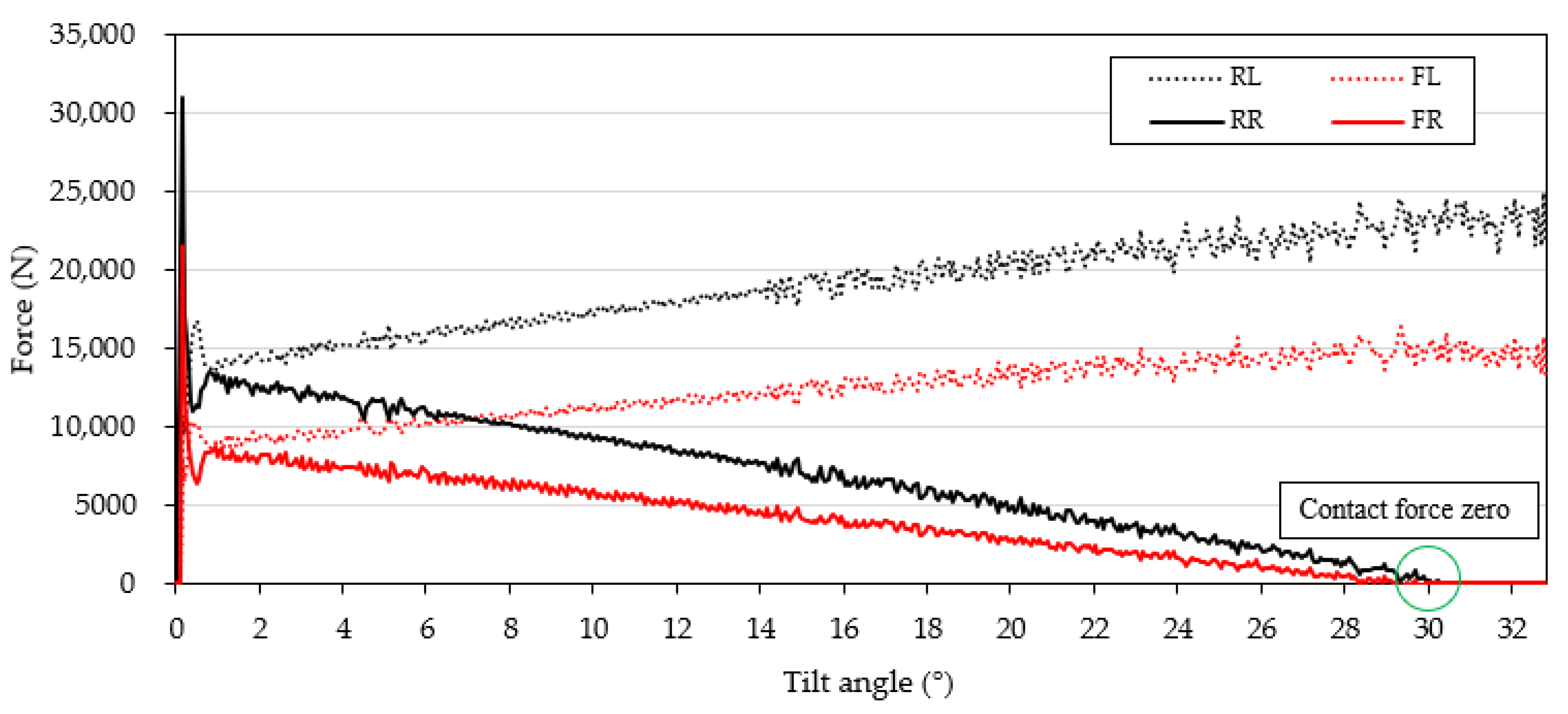
Figure 12 is a graph showing the contact force between the ground and the wheel. The x-axis consists of the tilt angle, and the y-axis consists of the contact force between the ground and the wheel. The rear left and front left wheels were tilted to one side and the contact force showed a gradual increase. It was observed that 0 N contact force on the rear right and front right wheel at approximately 30°.

Figure 12.
Result of simulation for rollover angle of the tractor, where RL is the rear left wheel, RR is the rear right wheel, FL is the front left wheel, and FR is the front right wheel.
Using an actuator limited to 200 mm, the overturning angle was found through dynamic simulations, and the overturning angle was compared with the actuator overturning angle.
The experimental results indicated that the highest improvement in the overturning angle was observed at an entry angle of 0°, where the overturning angle increased from 30.98° to 36.92°, resulting in an improvement of 19.0%. On the other hand, the lowest improvement in the overturning angle was observed at an entry angle of 60°, where the overturning angle increased from 46.64° to 48.53°, and an entry angle of 120°, where the overturning angle increased from 46.98° to 48.94°, resulting in an improvement of 4.0% (Table 3).
Table 3.
Tabular chart of rollover angles for with and without the actuator.
Considering the improved overturning angle with the actuator, the overturning angles from 0° to 180° were higher than those from 180° to 345°. The reason was that there was a CoG on the opposite side of the downward slope. From 180° to 345°, the overturning angles were low because the CoG was inclined downward.
The overturning angle was the highest and most stable at 120°. The reason for this was that not only was the CoG facing in the opposite direction of inclination, but each wheel was also supported diagonally to the ground. The results demonstrated that controlling the suspension actuators led to improvements in all measured overturning angles.
Through the simulation results mentioned above, it was confirmed that the method of adjusting the height of the individual active suspension applied to each wheel of the tractor effectively contributes to the prevention of rollover accidents. From the results in this study, using an individual active suspension system to prevent the driver from an overturning accident is suggested by adjusting the length of each actuator in the whole driving period. These results will contribute to improving the safety of tractors.
4. Conclusions
In this study, a simulation was used to analyze the effect of active suspension with individual actuators on tractor stability. Experiments with rollovers at all angles, both without and with actuators, have shown that tractors with actuators have improved rollover angles. The results suggest that adjusting the suspension actuator positively affects the stability of the tractor and increases the overturning angle. Therefore, the attitude control of the tractor using suspension actuators is an effective way to improve the overturning angle.
Safety devices, such as ROPS and seat belts, are implemented to ensure the safety of drivers from overturning accidents, but they do not effectively prevent overturning accidents. In this regard, this study proposed a new approach to preventing tractor overturning accidents through individual suspension control using actuators. Using a rotation transformation matrix equation, the height of each actuator could be adjusted according to the attitude and inclination angle of the tractor. These individual suspension control systems aim to improve tractor stability and reduce the risk of overturning accidents.
Thereafter, considering the speed of the actuator, the reactivity of posture control through actuator control should be evaluated according to the driving environment of a tractor. To this end, the effectiveness of this method must be verified by referring to experiments or references on the control and motion response of actuators. In addition, the effect of control should be confirmed by comparing the driving speed and slope entry speed of the tractor with the reaction of the actuator. The following will be further studied to improve the control system of actuators and improve its reactivity. (1) Actuator control according to the driving environment; (2) relationship between the driving speed and actuator response; and (3) relationship between the gradient entry speed and actuator response. Research will be conducted in this order to verify the effectiveness of actuator control and to improve the safety of tractors.
Author Contributions
Conceptualization, J.S. and Y.K.; methodology, S.K.; software, J.S.; validation, J.S.; analysis, J.S.; writing—original draft preparation, J.S.; writing—review and editing, J.S. and S.K.; visualization, J.S.; supervision, Y.H.; project administration, Y.H.; funding acquisition, Y.H. All authors have read and agreed to the published version of the manuscript.
Funding
This work was supported by the Korea Institute of Planning and Evaluation for Technology in Food, Agriculture, and Forestry (IPET) through Eco-friendly Power Source Application Agricultural Machinery Technology Development Program, funded by the Ministry of Agriculture, Food, and Rural Affairs (MAFRA) (322047-5).
Institutional Review Board Statement
Not applicable.
Data Availability Statement
The data presented in this study are available within the article.
Conflicts of Interest
The authors declare no conflicts of interest.
References
- He, Z.; Song, Z.; Wang, L.; Zhou, X.; Gao, J.; Wang, K.; Yang, M.; Li, Z. Fasting the stabilization response for prevention of tractor rollover using active steering: Controller parameter optimization and real-vehicle dynamic tests. Comput. Electron. Agric. 2023, 204, 107525. [Google Scholar] [CrossRef]
- Kang, S.; Kim, Y.; Park, H.; Kim, Y.; Woo, S.; Uyeh, D.D.; Ha, Y. Rollover Safety and Workable Boundary Suggestion of an Agricultural Platform with Different Attachments. Agriculture 2022, 12, 1148. [Google Scholar] [CrossRef]
- Son, J.; Kim, Y.; Kang, S.; Ha, Y. Enhancing Safety through Optimal Placement of Components in Hydrogen Tractor: Rollover Angle Analysis. Agriculture 2024, 14, 315. [Google Scholar] [CrossRef]
- Jang, M.-K.; Hwang, S.-J.; Nam, J.-S. Simulation Study for Overturning and Rollover Characteristics of a Tractor with an Implement on a Hard Surface. Agronomy 2022, 12, 3093. [Google Scholar] [CrossRef]
- U.S. Bureau of Labor Statistics. Fatal occupational injuries by industry and event or exposure. In Injuries, Illnesses, and Fatalities; U.S. Bureau of Labor Statistics: Washington, DC, USA, 2021. [Google Scholar]
- Antunes, S.M.; Cordeiro, C.; Teixeira, H.M. Analysis of fatal accidents with tractors in the Centre of Portugal: Ten years analysis. Forensic Sci. Int. 2018, 287, 74–80. [Google Scholar] [CrossRef] [PubMed]
- Rondelli, V.; Casazza, C.; Martelli, R. Tractor rollover fatalities, analyzing accident scenario. J. Saf. Res. 2018, 67, 99–106. [Google Scholar] [CrossRef]
- Aysel, A.; Muharrem, K. Trailer-Attached Two-Wheel Tractor (Patpat) Accidents on Roads in Turkey. J. Agric. Fac. Mustafa Kemal Univ. 2018, 23, 165–180. [Google Scholar]
- Moreschi, C.; Da Broi, U.; Cividino, S.R.S.; Gubiani, R.; Pergher, G.; Vello, M.; Rinaldi, F. The Analysis of the Cause-Effect Relation between Tractor Overturns and Traumatic Lesions Suffered by Drivers and Passengers: A Crucial Step in the Reconstruction of Accident Dynamics and the Improvement of Prevention. Agriculture 2017, 7, 97. [Google Scholar] [CrossRef]
- Facchinetti, D.; Santoro, S.; Galli, L.E.; Pessina, D. Agricultural Tractor Roll-Over Related Fatalities in Italy: Results from a 12 years Analysis. Sustainability 2021, 13, 4536. [Google Scholar] [CrossRef]
- Yuya, A.; Masami, M. Theoretical Verification of Driving Force Control System for the Suppression of the Dynamic Pitching Angle of Tractors. Eng. Agric. Environ. Food 2022, 15, 13–23. [Google Scholar]
- Kumar, S.; Kumar, A.; Pranav, P.K. Design and Development of Drop Centre Axle for 2WD Tractor. In Research into Design for a Connected World: Proceedings of ICoRD; Springer: Singapore, 2019; Volume 1, pp. 941–953. [Google Scholar]
- Vita, L.; Gattamelata, D.; Pessina, D. Retrofitting Agricultural Self-Propelled Machines with Roll-Over and Tip-Over Protective Structures. Safety 2021, 7, 46. [Google Scholar] [CrossRef]
- Liu, B.; Bulent, K. SafeDriving: A mobile application for tractor rollover detection and emergency reporting. Comput. Electron. Agric. 2013, 98, 117–120. [Google Scholar] [CrossRef]
- Gonzalez, D.O.; Martin-Gorriz, B.; Berrocal, I.I.; Hernandez, B.M.; Garcia, F.C.; Sanchez, P.M. Development of an automatically deployable roll overprotective structure for agricultural tractors based on hydraulic power: Prototype and first tests. Comput. Electron. Agric. 2016, 124, 46–54. [Google Scholar] [CrossRef]
- Ayers, P.; Khorsandi, F. Reducing tractor rollover fatalities: Progress in ROPS technology. Am. Soc. Agric. Biol. Eng. 2017, 24, 6–7. [Google Scholar]
- Qin, J.; Zhu, Z.; Ji, H.; Zhu, Z.; Li, Z.; Du, Y.; Song, Z.; Mao, E. Simulation of active steering control for the prevention of tractor dynamic rollover on random road surfaces. Biosyst. Eng. 2019, 185, 135–149. [Google Scholar] [CrossRef]
- Gattamelata, D.; Puri, D.; Vita, L.; Fargnoli, M. A Full Assistance System (FAS) for the Safe Use of the Tractor’s Foldable Rollover Protective Structure (FROPS). AgriEngineering 2023, 5, 15. [Google Scholar] [CrossRef]
- Ayers, P.; Khorsandi, F.; Wang, X.; Araujo, G. ROPS designs to protect operators during agricultural tractor rollovers. J. Terramechanics 2018, 75, 49–55. [Google Scholar] [CrossRef]
- Franceschetti, B.; Rondelli, V.; Ciuffoli, A. Comparing the influence of Roll-Over Protective Structure type on tractor lateral stability. Saf. Sci. 2019, 115, 42–50. [Google Scholar] [CrossRef]
- Pascuzzi, S.; Anifantis, A.S.; Santoro, F. The Concept of a Compact Profile Agricultural Tractor Suitable for Use on Specialised Tree Crops. Agriculture 2020, 10, 123. [Google Scholar] [CrossRef]
- Kise, M.; Zhang, Q. Sensor-in-the-loop tractor stability control: Look-ahead attitude prediction and field tests. Comput. Electron. Agric. 2006, 52, 107–118. [Google Scholar] [CrossRef]
- Qin, J.; Wu, A.; Song, Z.; He, Z.; Suh, C.S.; Zhu, Z.; Li, Z. Recovering tractor stability from an intensive rollover with a momentum flywheel and active steering: System formulation and scale-model verification. Comput. Electron. Agric. 2021, 190, 106458–106469. [Google Scholar] [CrossRef]
- Ni, Z.; He, Y. Design and validation of a robust active trailer steering system for multi-trailer articulated heavy vehicles. Veh. Syst. Dyn. 2019, 57, 1545–1571. [Google Scholar] [CrossRef]
- Jia, W.; Zhang, W.; Ma, F.; Wu, L. Attitude Control of Vehicle Based on Series Active Suspensions. Actuator 2023, 12, 67–86. [Google Scholar] [CrossRef]
- Baek, S.M.; Kim, W.S.; Kim, Y.S.; Baek, S.Y.; Kim, Y.J. Development of a simulation model for HMT of a 50 kW class agricultural tractor. Appl. Appl. Sci. 2020, 10, 4064. [Google Scholar] [CrossRef]
- Pawar, N.M.; Velaga, N.R. Modelling the influence of time pressure on reaction time of drivers. Transp. Res. Part F Traffic Psychol. Behav. 2020, 72, 1–22. [Google Scholar] [CrossRef]
- Zheng, E.; Cui, S.; Yang, Y.; Xue, J.; Zhu, Y.; Lin, X. Simulation of the Vibration Characteristics for Agricultural Wheeled Tractor with Implement and Front Axle Hydropneumatic Suspension. Shock Vib. 2019, 2019, 91345312. [Google Scholar] [CrossRef]
- Watanabe, M.; Sakai, K. Identifying tractor overturning scenarios using a driving simulator with a motion system. Biosyst. Eng. 2021, 210, 261–270. [Google Scholar] [CrossRef]
- Gao, J.; Yin, C.; Yuan, G. Warning and active steering rollover prevention control for agricultural wheeled tractor. PLoS ONE 2022, 17, e028021. [Google Scholar] [CrossRef]
- Chowdhury, M.; Islam, M.N.; Iqbal, M.Z.; Islam, S.; Lee, D.H.; Kim, D.G.; Jun, H.J.; Chung, S.O. Analysis of Overturning and Vibration during Field Operation of a Tractor-Mounted 4-Row Radish Collector toward Ensuring User Safety. Machines 2020, 8, 77–91. [Google Scholar] [CrossRef]
- Chowdhury, M.; Ali, M.; Habineza, E.; Reza, M.N.; Kabir, M.S.N.; Lim, S.J.; Choi, I.S.; Chung, S.O. Analysis of Rollover Characteristics of a 12 kW Automatic Onion Transplanter to Reduce Stability Hazards. Agriculture 2023, 13, 652–669. [Google Scholar] [CrossRef]
- Kim, W.S.; Siddique, M.A.A.; Kim, Y.J.; Jung, Y.J.; Baek, S.M.; Baek, S.Y.; Kim, Y.S.; Lim, R.G. Simulation of the Rollover Angle of a Self-Propelled Radish Harvester for Different Load Conditions. Appl. Sci. 2022, 12, 10733–10748. [Google Scholar] [CrossRef]
- Jung, Y.J.; Lim, R.G.; Choi, C.H.; Kim, Y.J. Analysis of Overturning Angle for Radish Harvester. Korean Soc. Agric. Mach. 2019, 1, 458–459. [Google Scholar]
Disclaimer/Publisher’s Note: The statements, opinions and data contained in all publications are solely those of the individual author(s) and contributor(s) and not of MDPI and/or the editor(s). MDPI and/or the editor(s) disclaim responsibility for any injury to people or property resulting from any ideas, methods, instructions or products referred to in the content. |
© 2024 by the authors. Licensee MDPI, Basel, Switzerland. This article is an open access article distributed under the terms and conditions of the Creative Commons Attribution (CC BY) license (https://creativecommons.org/licenses/by/4.0/).