1. Introduction
The structural health of an aircraft is crucial to flight safety and performance [
1,
2,
3]. Traditional inspection methods heavily rely on manual visual checks and conventional detection techniques, which are inadequate for meeting rapid and comprehensive inspection requirements. This challenge is particularly pronounced in composite material structures, where traditional methods such as tap testing and ultrasonic testing are both time-consuming and incapable of providing real-time, large-scale assessments of the internal structure [
4]. Nevertheless, the use of composite materials in aircraft structures is on the rise, especially in next-generation aircraft such as the Boeing 787, Airbus A380, F-35, AH-1W, and others [
5]. However, the brittleness of composite materials under impact loads limits their application to aircraft structures. Low-speed impacts, even with minimal surface indentations, can lead to extensive delamination, a type of damage known as nearly invisible impact damage, which may significantly degrade structural performance and result in buckling failure under high compressive loads [
6].
Hence, there is a pressing need to develop improved and more effective methods for detecting such damage. While some research has proposed structural detection methods for aircraft exteriors, practical validation is still needed [
7]. Alternatively, promising research results and experimental validations may be hindered from executing large-scale and rapid inspection methods due to equipment constraints. Previous studies by Christian Garnier et al. used non-destructive testing to inspect aerospace defects in composite structures, comparing three NDT methods. Their results indicated that infrared thermography and shearography could produce results more rapidly (around 10 s) than ultrasonic testing [
8]. However, these experiments were conducted in a controlled laboratory setting with related composite material attachments. Lucas Braga Carani proposed embedding sensors within composite material panels to detect damage throughout the entire composite material [
9]. Although this method offers real-time information on delamination, it adds complexity and high costs to the material itself and does not address current issues in aircraft composite structure inspection. K. Diamanti et al. used Lamb wave-based scanning technology to identify internal damage in multi-layer composite structures, particularly embedded ultrasonic non-destructive testing, which is especially suitable for laminated composite structures [
10]. However, challenges such as high costs and inapplicability to existing aircraft composite structures persist. Martin Bugaj et al.’s research explains that connecting common activities during drone and aircraft operations may reduce the time required for pre-flight checks, thereby enhancing aircraft operation efficiency [
11]. Andrej Novák et al. suggest that employing drones for visual inspections before and after flights can decrease the incidence of faults potentially stemming from human factors, thereby improving aircraft operation efficiency [
12,
13]. In their review article, Ramazan Duvar et al. note that precisely controlling damages, such as cracks, burns, and corrosion, is essential during aircraft maintenance. Consequently, this process may require a significant amount of time. In situations requiring swift control, errors may not be detected accurately. Since the control process is typically conducted visually, it is susceptible to human error. Therefore, visual-assisted defect detection technology is necessary [
14].
Presently, aircraft inspections (including pre-flight, transit, and daily inspections) are manually conducted by inspectors who visually inspect for defects. Inspection methods involve personnel conducting walk-around checks on the ground, but these methods cannot reveal aircraft composite materials’ internal structural conditions. Current inspections of composite material structures primarily rely on methods such as tap testing and ultrasonic testing, which are time-consuming and labor-intensive. In addressing these challenges, this study’s primary objective was to propose an integrated system where personnel carry infrared thermal imaging cameras for real-time monitoring of aircraft composite material structures. Simultaneously, the system uses image visual recognition technology to detect defects in composite material fuselages, overcoming the limitations of traditional inspection methods. The design and application of this system aim to enhance flight safety, reduce inspection time, and minimize potential hazards associated with high-altitude operations.
2. Materials and Methods
2.1. Unmanned Aerial Vehicle (UAV)
This study used a DJI Mavic Enterprise Dual unmanned aerial vehicle (UAV) designed for industrial applications to conduct experiments and acquire infrared images. The UAV specifications are shown in
Table 1. With high maneuverability and stability, this multi-rotor UAV is an ideal choice for aerial inspections. Moreover, studies have noted that UAVs equipped with multispectral and thermal imaging instruments provide richer inspection data [
15,
16]. This UAV features advanced flight control systems and is equipped with high-resolution visible light and thermal imaging cameras, enabling comprehensive inspections of the aircraft’s exterior during flight.
2.2. Thermal Imaging Detection
Thermal imaging technology has extensive applications in aircraft inspection. Thermal cameras can capture objects’ surface temperature distribution and detect potential defects by analyzing temperature anomalies. Relevant literature indicates that thermal imaging detection technology can provide high sensitivity and resolution for composite material structures [
17,
18]. In this study, we employed machine learning and image processing techniques to precisely analyze thermal images and detect defects in composite material structures. Infrared thermal imaging and shearography also produce rapid results [
19]. Additionally, using infrared thermal imaging (IRT) as a non-destructive assessment technique for detecting surface defects in composite material structures has become increasingly attractive. Extensive field research has been conducted to obtain qualitative results for simple structures [
20,
21,
22,
23]. This study proposes the use of infrared thermal imaging characteristics combined with backend image analysis to accurately calculate defect severity and make judgments.
2.3. Image Visual Recognition
Image visual recognition technology also plays a crucial role in defect detection. Through training deep neural networks, automatic classification and recognition of complex images can be achieved. Previous research indicates significant success in industrial inspections and image analysis for structural defect detection using UAVs [
24,
25,
26,
27,
28]. This study adopted similar methods to establish a detection model for visual recognition of aircraft composite material structures.
2.4. Evaluation of Experimental Method for Detection Materials
Our experiments involved using damaged engine cowlings for detection and comparing changes in the mechanical performance, dimensions, and strength of known defects in composite materials before and after repair, as well as the repair process and internal conditions, as shown in
Figure 1. This choice was based on their representativeness as a composite material and practicality for this study, as engine cowlings are commonly used in aircraft applications.
2.5. Experimental Setup
In this study, a new method was developed to establish a composite material structure detection and analysis system for aircraft. Our goal was to enable the system to detect, identify, analyze, and post-process defects in aircraft composite material structures within a short period. The system should also provide reliable, accurate, and immediate information about the condition of the aircraft’s composite material structure. To achieve this, the experiment used specialized visual and thermal imaging sensors mounted on a UAV to monitor the condition of the aircraft’s composite material structure. They also scanned external and internal structural defects and sent them to the ground control station for analysis. In the following sections, particular emphasis is placed on IR analysis and comparison.
The innovative approach in this study involved combining a UAV with a detection instrument (FLIR Duo R) equipped with both visible light and IR imaging capabilities for inspecting the exterior structure of aircraft composite materials.
Figure 2 illustrates the proposed system using UAV technology to monitor the aircraft’s exterior structure. Before conducting the inspection, the aircraft’s exterior structure must have a radiance of over 700 W/m
2 and a temperature above 50 °C [
29,
30]. The inspection procedure involves the UAV capturing fixed-point shots of the aircraft, using the integrated thermal camera (FLIR Duo R) for capturing aerial infrared images. This includes visual images, thermal images, and temperatures of the aircraft structure, which are then transmitted in real-time through the integrated RF channel to the ground station for image analysis. However, interpreting captured IR images can be challenging due to factors such as image quality, weather conditions during inspection, reflections, and shadows. Therefore, using software tools (MATLAB 2020b)to facilitate the detection of defects and faults would be beneficial.
2.6. Innovative Methods
In this study, we propose an algorithm to process acquired infrared images in MATLAB. Image processing techniques such as image segmentation, binary image conversion, filtering, and 3D image analysis were used to analyze the condition of aircraft composite material structures. Image processing is a useful technique to clearly identify delamination within composite materials and assess internal delamination severity. Additionally, this technique can provide comprehensive information about composite materials’ internal condition.
Typically, most IR images are in RGB format, so the first step is to convert the images from RGB to grayscale. This step is performed not only to enhance the resolution and color adoption of the images, but also to facilitate diagnostic procedures. Subsequently, the images must be filtered through common filters (such as Gaussian, mean, and median) to eliminate noise and reduce sharpening on the images. In practice, filtering techniques are performed as preprocessing for image processing.
The Gaussian filter is often used to reduce noise and remove unnecessary details from IR images. Additionally, internal defects and honeycomb structures within composite materials can affect temperature uniformity. Therefore, temperature propagates unevenly on the surface of composite materials. Binary transformation must be applied to filtered images to distinguish between healthy and defective composite materials. In this process, the image pixels are divided into black and white, representing cold and hot areas on the surface of the composite material, respectively. Simultaneously, the binary image provides extensive information about the composite material ’s degradation percentage. To gain a clearer understanding of whether the composite material has defects, the filtered image is then transformed from binary into 3D images, allowing for a more accurate assessment of the composite material. Additionally, the damaged area size can be calculated, providing a basis for comparison in subsequent inspections and predicting the time required for future maintenance, thereby improving maintenance control efficiency. The analytical process is illustrated in
Figure 3.
3. Results
To enhance the credibility and rigor of our research, the experiment was divided into two parts for comparative analysis. Firstly, testing and verification of the research method were conducted on materials with known defects. After obtaining the expected results from testing and verification, further tests were performed on composite materials with unknown defects to confirm the feasibility of real-field validation.
3.1. Tested Materials-Engine Cowling
The tested material in this experiment was an engine cowling manufactured from honeycomb-type composite materials removed from an aircraft for experimentation. A dismantled engine cowling was used in this experiment to facilitate confirmation of the defect’s location during testing and simulate conditions after sunlight exposure for capturing IR images. The analysis results of the tested material are described below.
3.1.1. Comparison before and after Repair of Tested Material
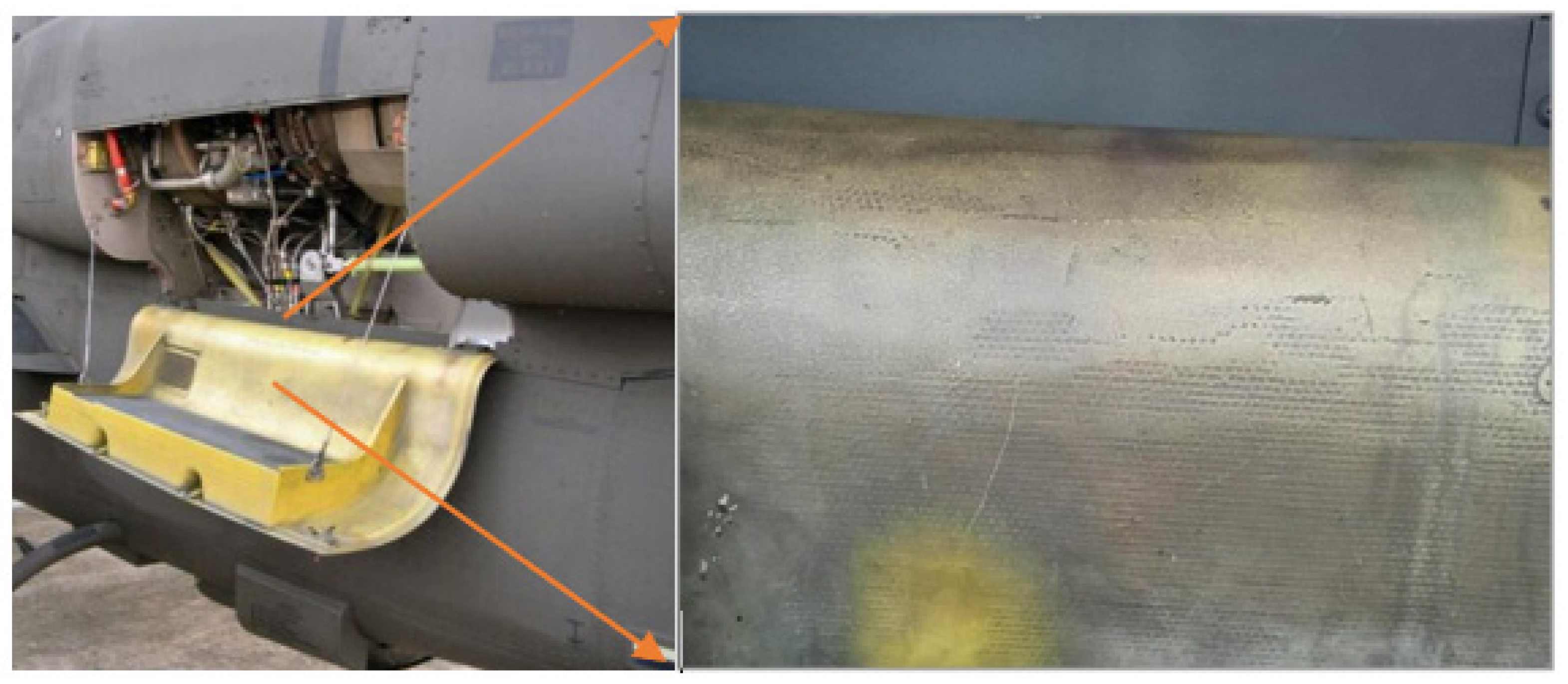
In the visible light image of the engine cowling shown in
Figure 4a, the red box indicates a known defect. However, the defect’s location is not discernible in the visible light image. On the other hand, the green arrow direction in
Figure 4a indicates the location of the completed repair of the defect. Although the repair area had not been repainted, the IR image in
Figure 4b shows a bright yellow area within the red box, indicating that its relative temperature is higher than in other areas. At the same time, in the direction of the green arrow in
Figure 4b, delamination is no longer visible at the repaired site. Additionally, manual inspection confirmed that there was no delamination in the repaired area.
3.1.2. Detection Using the Proposed Method
This research method uses infrared images (
Figure 4b) to identify areas of delamination in composite materials that cannot be discerned in visible light images, as shown in
Figure 4a. Although the red box in the IR image of
Figure 4b indicates the defect region, the exact size of the delamination cannot be accurately determined. In such situations, the 3D images developed in this study can clearly label the defect location and assess the severity of delamination, as depicted in
Figure 5a–d. Additionally, 3D images facilitate area transformation to determine the defect region, as shown in
Figure 5a–d. The temperature settings can be obtained from the Z-values in
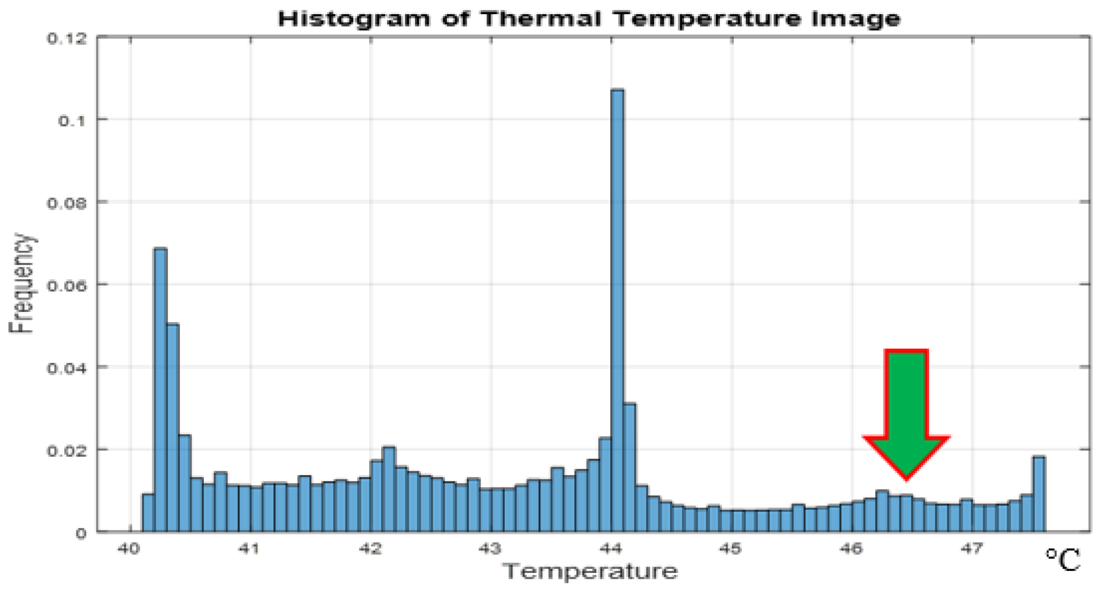
Figure 5 before inspection, which represent temperature measurements of the aircraft exterior. Moreover, based on differences between the defect and normal areas, especially the region between the defect and normal area, the results of defect localization using the 3D images are influenced. The 3D images can also mark relatively high temperature points and coordinates to determine the defect region’s size. On the other hand, after manual inspection, the temperature of the defect location in this case was 46.5 °C, matching the Z-values marked in
Figure 5 between bright yellow and orange. Therefore, the region with Z-values above 46.5 °C was designated as the defect area.
The relative temperature proportion in the histogram was used for secondary confirmation of the defect area, as illustrated in
Figure 6. Finally, the defect area and size were marked and positioned using the location marks from the 3D images and the confirmed value (46.5 °C, green arrow) from the histogram. These guidelines provide maintenance personnel with a clear understanding of the required material quantity for preparation, facilitating calculations during the repair process.
3.2. Verification Testing Materials
Verification testing was conducted on a composite material attachment installed on an aircraft with unknown defects. This test aimed to validate the universality and applicability of the developed detection system. Experimental results were compared before and after the repair of known defects to examine the effects of the developed method on the composite material’s mechanical properties, damage size, and strength. Additionally, the testing assessed the system’s detection capability in situations where defects were unknown.
3.2.1. Case 1: AH-1W Helicopter Engine Inspection Pedal
This case involved the engine inspection pedal of an AH-1W helicopter. The experimental material was a honeycomb-type composite. Positioned near the engine, the experiment focused on the lower part of the engine cover, as shown in
Figure 7. This area served as the main attachment point for maintenance personnel to step on, making it a crucial component of the aircraft’s exterior structure. Consequently, it must meet high strength, lightweight, and heat resistance requirements. On the other hand, the engine inspection pedal is prone to causing delamination in composite materials. Therefore, we selected the engine inspection pedal of a randomly chosen AH-1W helicopter to verify the detection of unknown defects.
The visible light image in
Figure 8a shows no visible defects in the external condition. However, the IR image in
Figure 8b shows that the middle yellow and brighter areas of the engine inspection pedal are defective but the severity of the defect cannot be determined at present. After applying advanced analysis of this research, a binarization analysis was performed, as shown in
Figure 8c. The noise was removed using a Gaussian filter and, finally, a 3D image was constructed, as shown in
Figure 8d. Three-dimensional images were created to confirm the severity and location of the defect. In this case, the manually inspected temperature of the defect was 46.8 °C. Simultaneously, temperature differentials were used to establish a histogram, as shown in
Figure 8e. Using the values confirmed by the 3D image’s position markers and the histogram (46.8 °C), the defect range and size were identified. From the temperature proportion in the histogram, the amount of material required for the defect can be calculated. The innovative aspect of this research lies in determining the size of the repair material needed for the defect location and predicting the acceptable degree of the defect using combined information from the 3D image and histogram. This method can be used to schedule maintenance times for effective manpower and reduces material preparation time.
In
Figure 8b, the latitude and longitude of the acquired image are displayed in the bottom right corner. The brand name of the thermal imager is shown in the bottom left corner and a color bar is located on the right side. This information, except for the color bar, may potentially affect the interpretation of the image and will be cropped before analysis. Therefore, before conducting 3D image analysis, a binarization analysis was performed in this study, as shown in
Figure 8c. Additionally, any potentially influential information was converted to black to reduce errors.
3.2.2. Case 2: AH-1W Helicopter Aircraft Engine Cowling (Non-Pedal Section)
Case 2 involves the engine cowling in the non-pedal section, as shown in
Figure 9. It is also manufactured from composite materials, but unlike the pedal, it is constructed using carbon fiber layers. This design meets lightweight and heat-resistant requirements. However, composite materials manufactured with resin bonding may experience delamination issues due to their proximity to high-temperature areas.
The helicopter aircraft engine cowling (non-pedal section) analysis was conducted using the same steps and methods. Similarly, in the IR image shown in
Figure 10a, delamination areas can be roughly identified, but their severity cannot be confirmed. The image was then binarized, as shown in
Figure 10b. A 3D image was also constructed, as depicted in
Figure 10c. After manual inspection, the temperature at the location of the defect was 47.4 °C. Histograms were created based on temperature differences, as illustrated in
Figure 10d. The defect area and size were marked and positioned using the values confirmed by the 3D image and histogram (47.4 °C). The temperature proportions from the histogram were used to calculate the extent of the defect, providing a reference for maintenance personnel.
3.2.3. Case 3: AH-1W Helicopter Equipment Compartment Door
Case 3 involves an equipment compartment door manufactured from honeycomb composite material, as shown in
Figure 11a. Located in the tail boom section, the equipment compartment door is positioned near the engine exhaust port. Therefore, it must meet lightweight and heat-resistant requirements. On the other hand, honeycomb composite materials are prone to delamination due to their proximity to high-temperature areas.
This case focuses primarily on the analytical approach developed in this study. In the IR image in
Figure 11b, areas with suspected delamination are observed in the upper-left region, but the severity level cannot be confirmed. The image is binarized, as shown in
Figure 11c. A constructed 3D image is also shown in
Figure 11d. Different orientations of the 3D image were used to verify delamination severity and location. However, it is important to note that this 3D image has two bright yellow areas. The first is in the upper-left region, which corresponds to a defective area. The second area is directly above the image, corresponding to the engine exhaust port. These observations indicate that the image analysis in this study has certain limitations. When conducting image analyses, it is necessary to exclude high-temperature zones that may affect the IR image to ensure accuracy. Therefore, this case employed histograms based on different temperature differentials. Exercising caution when using such images for analysis is essential, as they may lead to potential misjudgments by maintenance personnel.
4. Discussion
In this study, preliminary tests were conducted prior to using thermal imaging as a research method. As illustrated in
Figure 4, the validated cases discussed in this article demonstrate the effectiveness of thermal imaging. Additionally, to mitigate unnecessary noise during image analysis, filters were integrated into the pattern analysis process. This enhancement ensured that post-analysis images were more precise and defined, helping engineers identify the severity of defects. This study’s primary experimental targets were aircraft with exterior composite structures, including fixed-wing and rotary-wing aircraft. We effectively detected exterior composite structures in aircraft, addressed blind spots in internal damage detection of composite structures, and reduced the error rate associated with manual visual inspections. Moreover, it also reduced the time required for pre-flight aircraft inspections.
The unmanned aerial vehicle (UAV) detection system used in this study has several technological advantages. Firstly, UAVs enable comprehensive inspections of aircraft exteriors, eliminating blind spots that manual visual inspections may overlook. Secondly, thermal imaging cameras on UAVs allow non-contact inspections, minimizing interference with the aircraft. As demonstrated in Cases 1 and 2, the feasibility of the proposed research methodology is evident. However, this study has limitations, particularly in Case 3, where images presented high-temperature areas in non-inspection zones, leading to potential misinterpretations. Therefore, before capturing UAV images, precautions should be taken, such as avoiding capturing images with excessive reflections and direct sunlight. These challenges also highlight certain technical aspects, including the accuracy of thermal imaging technology and the optimization of UAV flight paths.
The developed UAV detection system exhibits potential value in practicality and scalability. Practicality is evident in the system’s real-time ability to rapidly detect structural defects in aircraft, enhancing maintenance efficiency. Simultaneously, the developed system can be scaled to different aircraft models and diverse environmental conditions. Through real-time detection and repair of defects in composite material structures, we anticipate improvements in flight safety and reductions in potential accidents. The UAV detection system can promptly identify potential issues and facilitate timely repairs and maintenance to ensure the aircraft operates under optimal conditions.
Compared to traditional manual visual inspections, the UAV detection system has the advantage of reducing operational costs due to its faster detection speed and higher automation level. Advanced technology shortens inspection times, thereby reducing the labor and time associated with inspections. By developing an integrated UAV detection system, we expect to achieve efficient real-time monitoring, provide comprehensive coverage of composite material structures on aircraft exteriors, and enhance detection efficiency and accuracy.
The experiment in this study used a Hawker 400xp aircraft. In the inspection process, it was necessary to pre-set the drone’s flight path, as shown in
Figure 2. The time required for flight path planning was approximately 3 min. This research is considered the standard time needed for a qualified drone pilot. Inspection and analysis were conducted simultaneously. The Hawker 400xp aircraft was set to have eight inspection points, with a flight time of about 5 s between each point. Additionally, each inspection point required a stable 5–10 s. Each inspection was repeated three times following the flight path, capturing an image each time. Each inspection point was photographed three times to mitigate image analysis errors caused by reflections, shadows, or other uncontrollable factors affecting the aircraft’s appearance. In summary, the total time for each flight inspection ranged from 13 to 23 min.
By developing an integrated UAV detection system using thermal imaging and image recognition technologies, this research makes a significant breakthrough in the field of aircraft inspection. Future research can optimize the technical performance of the UAV detection system, enhancing thermal imaging and image processing accuracy. Additionally, expanding the system’s application scope to include different aircraft models and other industrial domains is feasible. In-depth research into the system’s practical application effects, long-term experiments to continuously improve stability and reliability, and monitoring are essential. In summary, the UAV detection system proposed in this study holds potential application value in the aircraft inspection domain and may become a crucial technology in future aircraft maintenance.
5. Conclusions
This study focuses on using unmanned aerial vehicles (UAVs) for the inspection and analysis of aircraft composite material structures, aiming to enhance flight safety, reduce operational costs, and improve aircraft availability. This study proposes the integration of UAVs with infrared cameras and real-time image transmission capabilities, coupled with MATLAB image analysis software (MATLAB 2020b) to analyze infrared (IR) images. Our results indicate that, in addition to obtaining real-time IR images, the internal health of the aircraft’s exterior composite material structure can be clearly discerned. The proposed procedure not only significantly shortens inspection time but also allows for real-time analysis of defect locations in IR images. Particularly in 3D imaging, the system displays the relative temperature of the inspected aircraft’s exterior composite material structure. It also addresses the severity of defects that may not be identifiable in IR images, achieving optimal results.


