Article

Innovative Hybrid UAV Design, Development, and Manufacture for Forest Preservation and Acoustic Surveillance

by
Gabriel Petre Badea
1,2,
Tiberius Florian Frigioescu
1,2,
Madalin Dombrovschi
1,2,
Grigore Cican
1,2,*,
Marius Dima
2,3,
Victoras Anghel
3 and
Daniel Eugeniu Crunteanu
2
1
National Research and Development Institute for Gas Turbines COMOTI, 220D Iuliu Maniu Av., 061126 Bucharest, Romania
2
Faculty of Aerospace Engineering, Polytechnic University of Bucharest, 1-7 Polizu Street, 011061 Bucharest, Romania
3
Autonomus Flight Technology R&D SRL, 152 Traian Street, 024044 Bucharest, Romania
*
Author to whom correspondence should be addressed.
Inventions 2024, 9(2), 39; https://doi.org/10.3390/inventions9020039
Submission received: 22 March 2024 / Revised: 4 April 2024 / Accepted: 8 April 2024 / Published: 10 April 2024
(This article belongs to the Special Issue Quadrotor UAV with Advanced Applications)

Abstract

:
The research described in this paper focuses on the development of an innovative unmanned aerial vehicle (UAV) tailored for a specific mission: detecting the acoustic signature emitted by chainsaws, identifying deforestation, and reporting its location for legality assessment. Various calculations were conducted to determine the optimal solution, resulting in the choice of a fixed-wing UAV. A comparative analysis between tri-rotor and quadcopter systems was performed, leading to the selection of the tri-rotor configuration. The primary objective of this study is to design an innovative hybrid UAV concept with key features including a fixed-wing design and integrated VTOL (vertical takeoff and landing) capability in the experimental model. The aircraft has been constructed using advanced materials such as fiber-reinforced polymer composites, manufactured using both conventional and advanced techniques like continuous fiber additive manufacturing and the use of a polymer matrix. Additionally, the aerodynamic configuration is optimized to achieve a cruise speed of approximately 50 km/h and a flight autonomy exceeding 3 h. The UAV has been equipped with payloads for mounting sensors to collect meteorological data, and crucially, the VTOL system has been optimized to vectorize thrust for improved performance during the transition from hover to cruise flight. This paper details the entire manufacturing and assembly process of the drone, covering both the structural framework and associated electrical installations. A dedicated sound detection system is incorporated into the drone to identify chainsaw noise, with the aim of preventing deforestation.

1. Introduction

Recent advancements in microcontrollers and sensor technologies have resulted in a substantial reduction in drone costs, rendering them more economically accessible. Unmanned aerial vehicles (UAVs) have garnered widespread recognition for their diverse applications across sectors, including surveillance, agriculture, healthcare, traffic management, inspections, and public safety [1,2]. They are extensively utilized in commercial ventures such as aerial surveys, photography, and cinematography.
UAVs are typically equipped with onboard sensors, facilitating the collection of geospatial data about their surroundings, and are remotely operated from a ground-based control station. Drones have demonstrated effectiveness in topographical mapping of volcanic terrains and detecting volcanic activities. Thiele et al. employed drones with thermal cameras, gas sensors, and other instrumentation to measure parameters related to volcanic activity, providing valuable data for predicting eruptions, executing rescue missions, conducting photogrammetry, monitoring infrastructure, and supporting delivery services [3].
UAVs also play a crucial role in geological exploration around volcanoes, enhancing operational efficiency, precision, and safety while reducing costs by minimizing the need for human intervention in hazardous areas [3]. This technology also facilitates mission planning and oversight from a control station. In both civil and industrial sectors, drones have proven instrumental in process optimization and executing missions in challenging environments, some of which may be entirely inaccessible to humans [4,5].
Consider the agricultural sector, where farmers face various challenges affecting crop quality. Drones offer an efficient and cost-effective means of collecting data on ecosystems and their variations due to factors like climate change, soil erosion, water availability, and extreme weather events. Drones are also deployed for activities such as crop spraying, saving time and optimizing yields [6].
In a study detailed in [7], the efficiency of drones in precision agriculture is demonstrated, with collected data used to generate 3D cartographic representations of agricultural plots for better analysis of vegetation density and soil heterogeneity.
Drones find diverse applications in the healthcare sector, including the delivery of medical supplies to remote or hard-to-reach areas and the transportation of blood samples and lab results [8].
In transportation, drones are used for tasks such as package delivery [9], traffic monitoring [10], and infrastructure inspections [11].
Drones also find application in various scientific disciplines, including agriculture (e.g., monitoring crops [12], disease detection [13], mapping fields for optimized fertilization and irrigation [14,15]), environmental science (e.g., wildlife monitoring [16,17], assessment of forest health [18], water quality monitoring [19], air quality monitoring [20]), oceanography (e.g., monitoring marine life [21], tracking ocean currents and tides [22]), archaeology (e.g., detailed site mapping [23], identification of hidden structures [24]), and disaster response (e.g., assessing damages [25], identifying victims [26], delineating boundaries [27], rapid extent mapping [28]).
In accordance with [29], UAVs can be categorized based on various parameters. These classifications provide a framework for organizing UAVs and comprehending their capabilities, limitations, and potential applications. The continuous progress and evolution of UAV technology have given rise to new classifications, blurring the traditional boundaries between them.
For instance, multi-rotor UAVs offer vertical takeoff and landing capabilities, enabling operation in complex terrain, albeit with limitations in battery capacity.
In contrast, traditional fixed-wing UAVs require dedicated runways for deployment. Hence, the tilt-rotor UAV (TRUAV) has emerged as a solution that combines the advantages of both UAV forms, offering flexible takeoff/landing capabilities and extended operational endurance [30,31]. To enhance the capabilities for which drones are designed, the use of AI has become a widely employed technique in current times [32,33,34]. Consequently, several studies employ AI on drones across various domains. Based on the missions and classifications outlined above, as well as the advantages associated with AI utilization, this paper aims to propose the design of an innovative hybrid-wing UAV concept equipped with an AI system for the detection of chainsaw sounds in forests to combat deforestation.
Regarding the use of drones in forest management, rotary-wing aircraft like helicopters and multicopters (e.g., quadcopters, octocopters) may not be optimal in large community forests as they have limited range and endurance due to their high power demand relative to battery capacity. However, they may be preferable to fixed-wing drones in situations where vertical ascent and descent are required but no landing strip is available. In contrast, fixed-wing aircraft possess gliding capabilities that enable longer flight endurance compared to rotary-wing aircraft, allowing them to operate effectively over larger distances. Regarding the use of drones in forest surveillance and environmental monitoring, there are several studies that employ various types and configurations of UAVs [35,36,37]. For example, source [38] presents a combined weightless neural network architecture for deforestation surveillance and visual navigation of unmanned aerial vehicles (UAVs); this was achieved using a fixed-wing UAV model Echar which does not have VTOL.
This novel concept possesses the following features: It incorporates a fixed-wing design. It includes a VTOL (vertical takeoff and landing) system that will be integrated into the experimental model. The aircraft will be constructed from advanced materials, specifically polymer composites reinforced with fibers, manufactured using both conventional and advanced technologies, including continuous fiber additive manufacturing and polymer matrices. Furthermore, it focuses on optimizing the aerodynamic configuration to achieve a cruising speed of approximately 50 km/h and an endurance exceeding 3 h. The UAV is designed to accommodate various payloads, such as meteorological data capture noise sensors, and most importantly, the optimization of the VTOL system to vectorize thrust for improved performance during the transition from hovering to cruising flight.

2. Materials and Methods

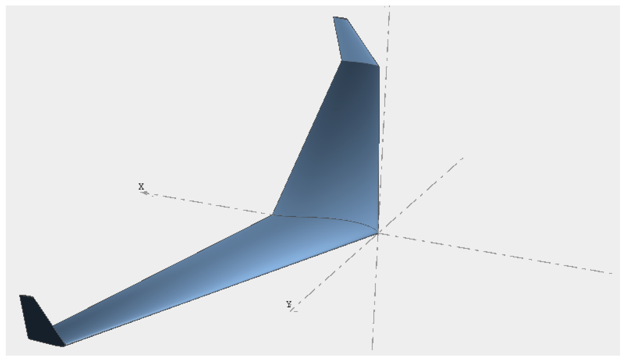
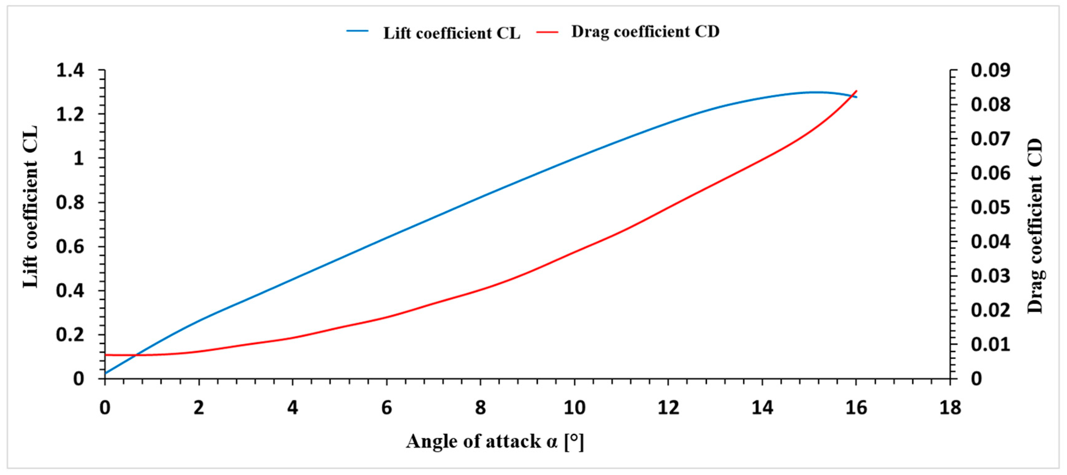
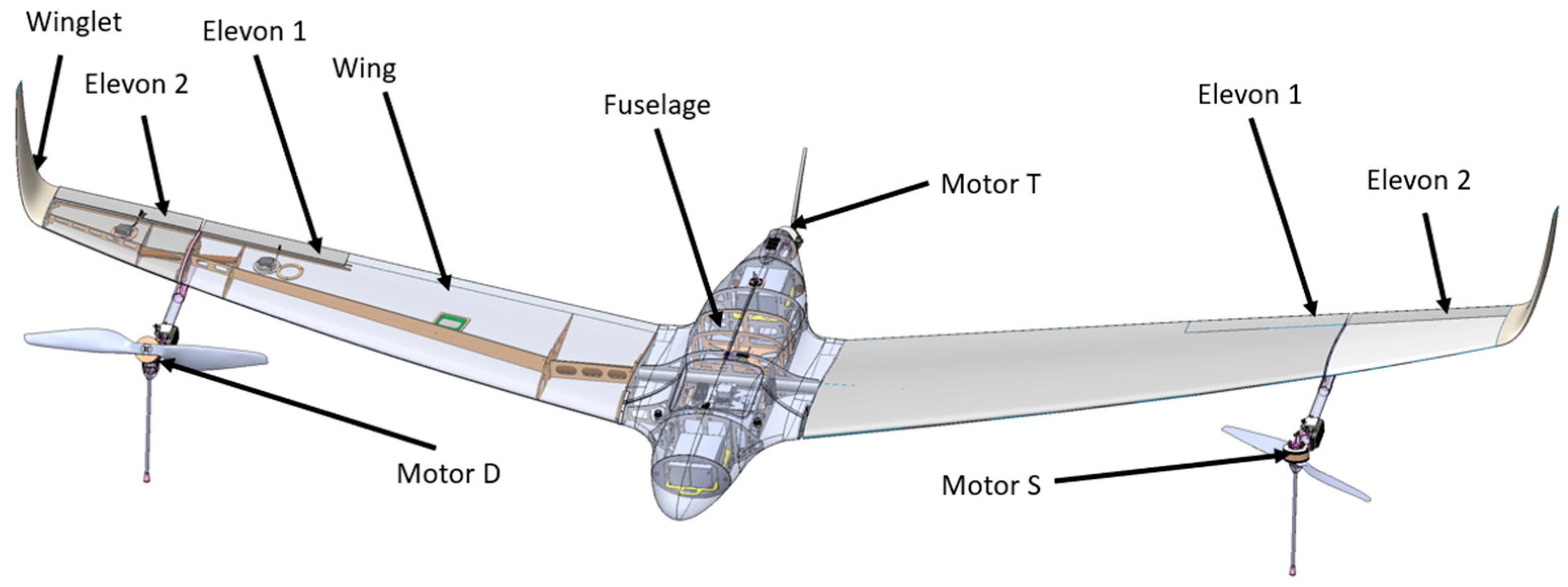
2.1. UAV Performance and Design

In order to define the most optimal configuration, a comparative study was conducted between a tri-rotor UAV and a quadcopter, aiming to further develop the optimal solution. Table 1 presents the comparisons between the requirements of the 3- and 4-rotor systems.
Therefore, with these two proposed VTOL configurations, a study was conducted to determine which multi-rotor configuration is optimal for the experimental model in the project, the optimal version in terms of flight autonomy. For this performance study, a theoretical flight simulator was created in the Matlab program, which studied the flight of the experimental model in both takeoff and cruising flight scenarios. Both VTOL configurations were tested on this route to ultimately compare overall performance.
The following inputs were considered for this performance study: UAV tri-rotor mass: 15 kg, UAV quad-rotor mass: 18 kg, moments of inertia, surfaces and dimensions of the model, and aerodynamic coefficients of the conceptual model.
For this study, a primitive conceptual model of the UAV was created. The primitive conceptual model was created using the XFLR5 v6.55 program and is shown in Figure 1.
A 4 m wingspan wing was considered, with winglets mounted at the ends. The winglets have a length of 200 mm and are positioned at 90° perpendicular to the wing. The chord length of the airfoil profile in the center of the wing is 500 mm, decreasing towards the tips to a size of 176 mm, and the tip of the winglets has a chord of 63 mm. The airfoil profile is constant along the entire length of the wing and is MH45. This conceptual model resulted in a wing area of 1.352 m2. The aspect ratio has a value of 13.831 in this case, and the trapezoidality ratio is 0.126. The aspect ratio value ensures a high flight autonomy, being close to the value of glider-type aircraft.
Within the XFLR5 program, this conceptual wing model was simulated, and two vectors containing the lift coefficient and drag coefficient as functions of the wing incidence angle were extracted. The simulated forward speed was set to 20 m/s. To use these vectors in the simulation program created in Matlab, it was necessary to create a polynomial equation describing the curve from the points obtained in the XFLR5 program. These points were taken at intervals of 0.5°, resulting in 32 points from 0 to 16 degrees.
For the input data, the motor performance was also introduced. For this conceptual model, the MN805-S KV170 motor with a carbon fiber propeller with a 26-inch diameter and an 8.5-inch pitch was chosen. Data were collected from the manufacturer’s performance table, and a polynomial equation was created to match the curve passing through the experimental points. The relevant data include the thrust generated by each motor coupled with this propeller and the respective power consumption.
The flight simulator within the Matlab program calculates certain data, presenting both the UAV platform with 3 rotors and the UAV platform with 4 rotors in takeoff from the ground to 100 m and then a fixed-wing flight over a distance of 10 km. During this time, all forces are calculated using the flight equations, and parameters such as speed and consumption are extracted for further analysis to compare the two categories of UAVs.
If we consider that in cruising flight, two motors generate equal thrust, and the onboard energy of the aircraft is 16 Ah, then for the aircraft to have a flight autonomy of 3 h, the energy consumption per motor must be 2.66 A.
Assuming a forward speed of 100 km/h, dimensional parameters of the experimental model, and a force balance along the forward direction using the motor specifications, it follows that the drag coefficient must be less than 0.245 for the flight autonomy to be achieved. The conceptual model has a drag force value of 0.08 at an incidence angle of 16°, thus comfortably meeting the autonomy objective.
The calculation algorithm behind the simulator developed in the Matlab program uses motion and balance equations. In both takeoff and cruising flight, a PID (proportional–integral–derivative) control system has been implemented to provide greater result accuracy [39].
Transitioning to the calculation algorithm of the theoretical simulator, a quadcopter-type multi-rotor has 4 commands used for all flight maneuvers. For a cascaded PID controller to be used in such a control case, a motor control matrix was created. The following figure illustrates the diagram of a quadcopter with the 4 labeled motors, with motors M1 and M4 having a clockwise rotation and motors M2 and M3 having a counterclockwise rotation, as shown in Figure 2a.
The same calculation and algorithm were designed for the tri-rotor version, where the M1 engine has a clockwise rotation, while the M2 and M3 engines have a counterclockwise rotation, as shown in Figure 2b.
Similarly, based on the moments provided by the thrust forces, angular accelerations were calculated to determine the aircraft’s rotational speeds. With all these equations, a system was implemented that takes the input parameters of the discussed conceptual model and uses these equations to elevate the aircraft to an altitude of 100 m and then translate it in a direction for 10 km. During this entire time, an energy consumption calculation was performed to make a comparison between the tri-rotor and quad-rotor.
For both the quad-rotor and tri-rotor, the theoretical trajectory is as follows:
  • Takeoff to an altitude of 100 m;
  • Maintaining an altitude of 100 m for 20 s;
  • Imposing a pitch angle of 60°;
  • Movement while maintaining altitude for a distance of 10 km;
  • Changing the pitch angle to 85° when the wing provides the necessary lift for the aircraft.

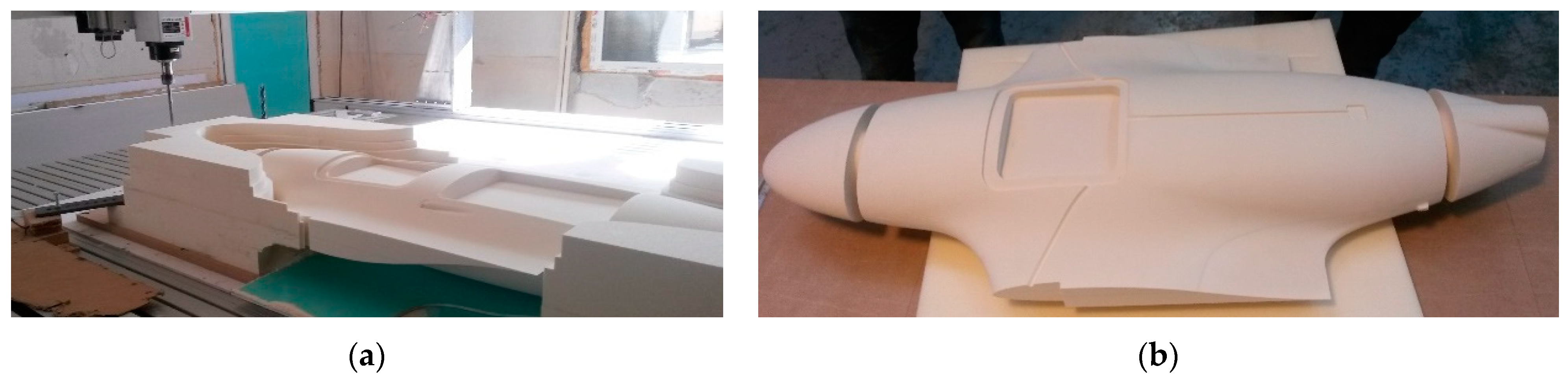
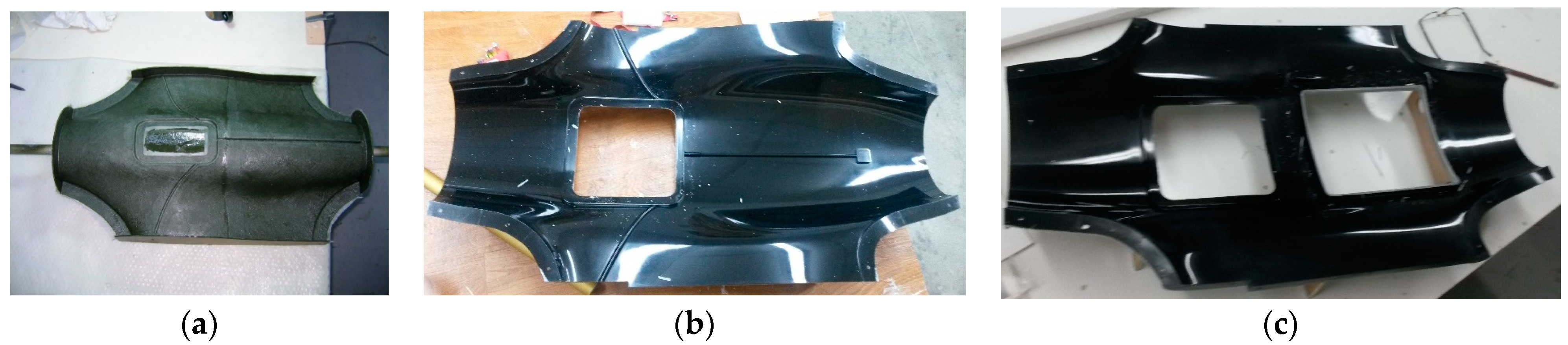
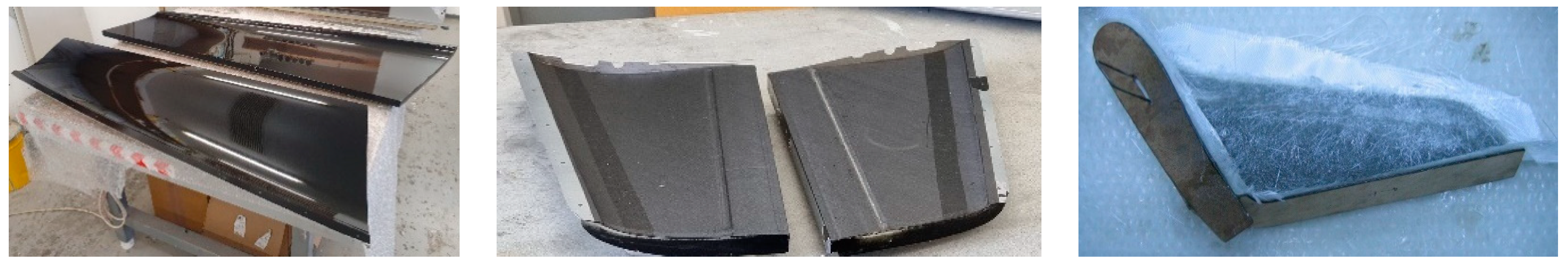
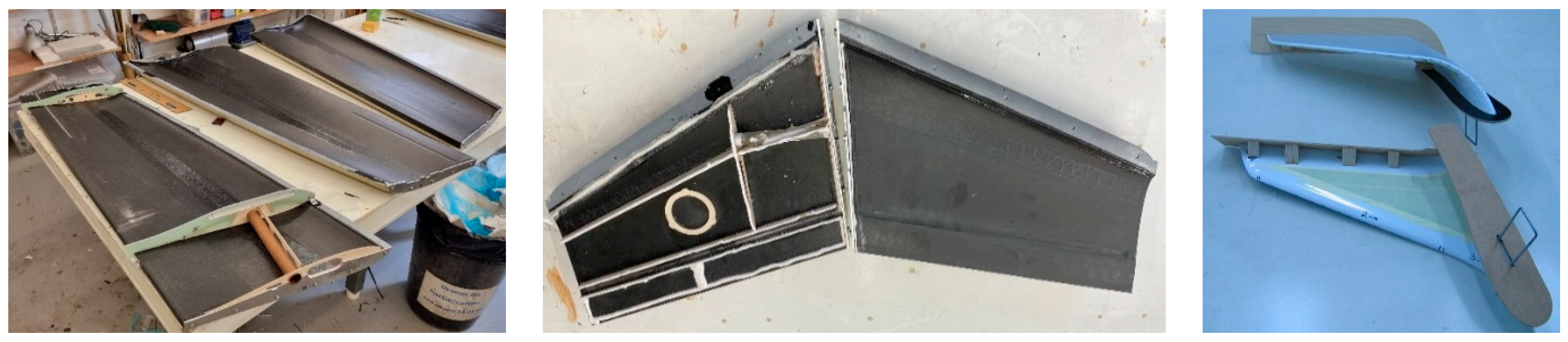
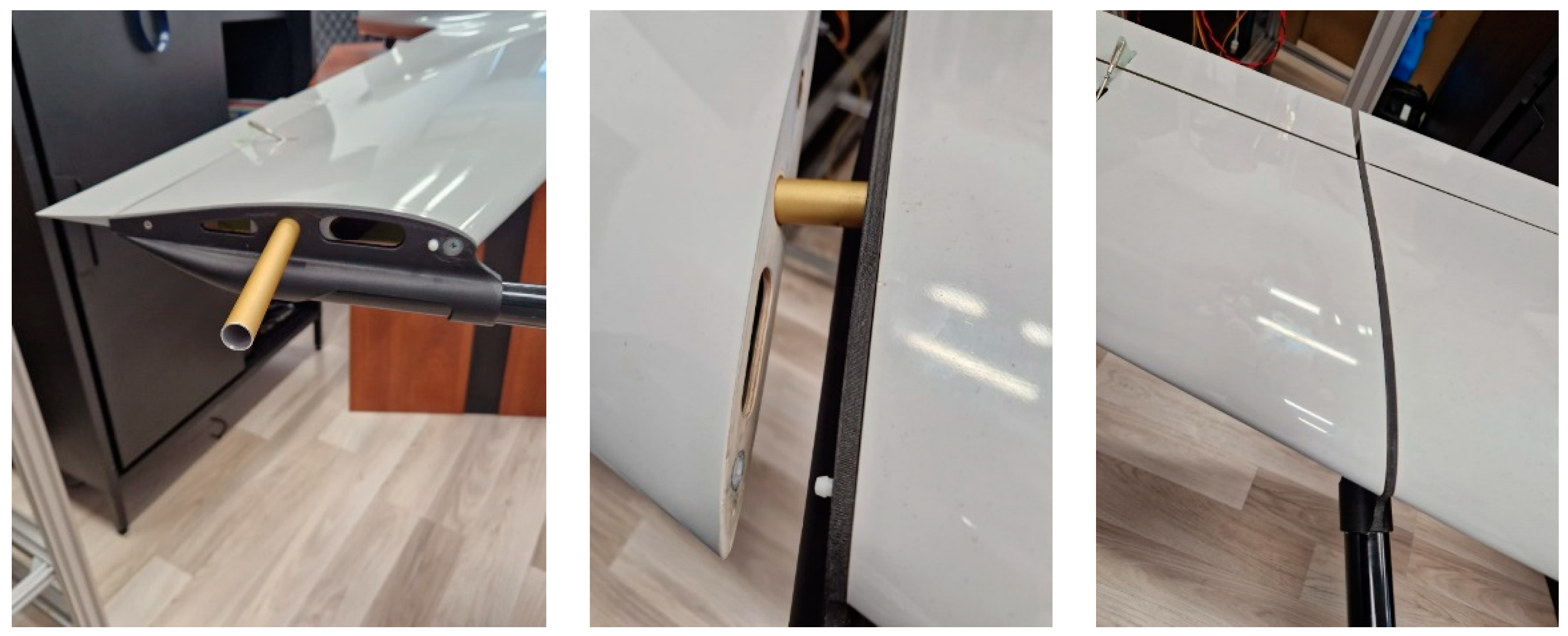
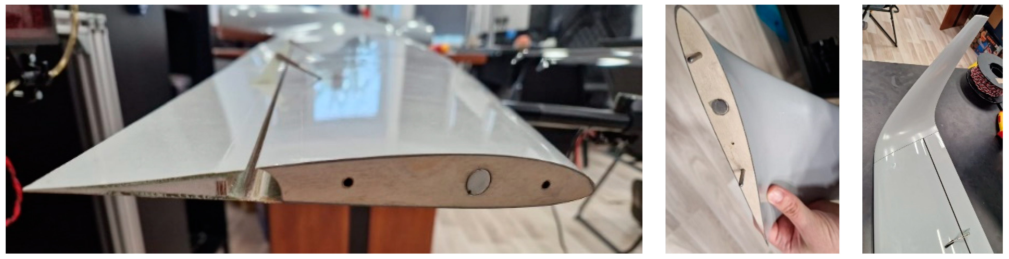
2.2. Manufacturing the Structure of the Experimental Model

To create the structural components and other elements of the hybrid UAV experimental model, the use of fiber-reinforced polymer composite materials (either in the form of fabrics or short fibers) and thermoplastic materials, either reinforced or unreinforced, was considered. Two categories of manufacturing technologies were targeted from the beginning of the project: conventional technologies for composite material structures and advanced technologies, such as additive manufacturing technology using specific methods that utilize polymer materials as raw materials.
Therefore, for the fabrication of the experimental model, fiber-reinforced composite materials manufactured through conventional methods will be used. In the case of the airframe, representing the central part of the drone composed of the fuselage, frontal part, and rear part of the fuselage, areas requiring strength will be made from a combination of CFRP (carbon-fiber-reinforced polymer) and GFRP (glass-fiber-reinforced polymer); more properties can be found in sources [40,41]. CFRP will be used to reinforce the structural resistance, while GFRP will be employed in areas where very high mechanical strength is not necessary.
Considering that electronic equipment will be installed inside the fuselage and will not be subjected to significant mechanical stress, glass fiber (GFRP) was chosen as the material. The primary reason for choosing this material is its ability to block electromagnetic fields and radiofrequency radiation, creating an electromagnetically isolated environment inside the fuselage.
As the most significant forces are concentrated on the wing, carbon fiber (CFRP) with superior mechanical properties was chosen for its construction. Molds were created for the manufacturing of the central part of the drone, including the fuselage, frontal part, rear part, wing, and winglets.

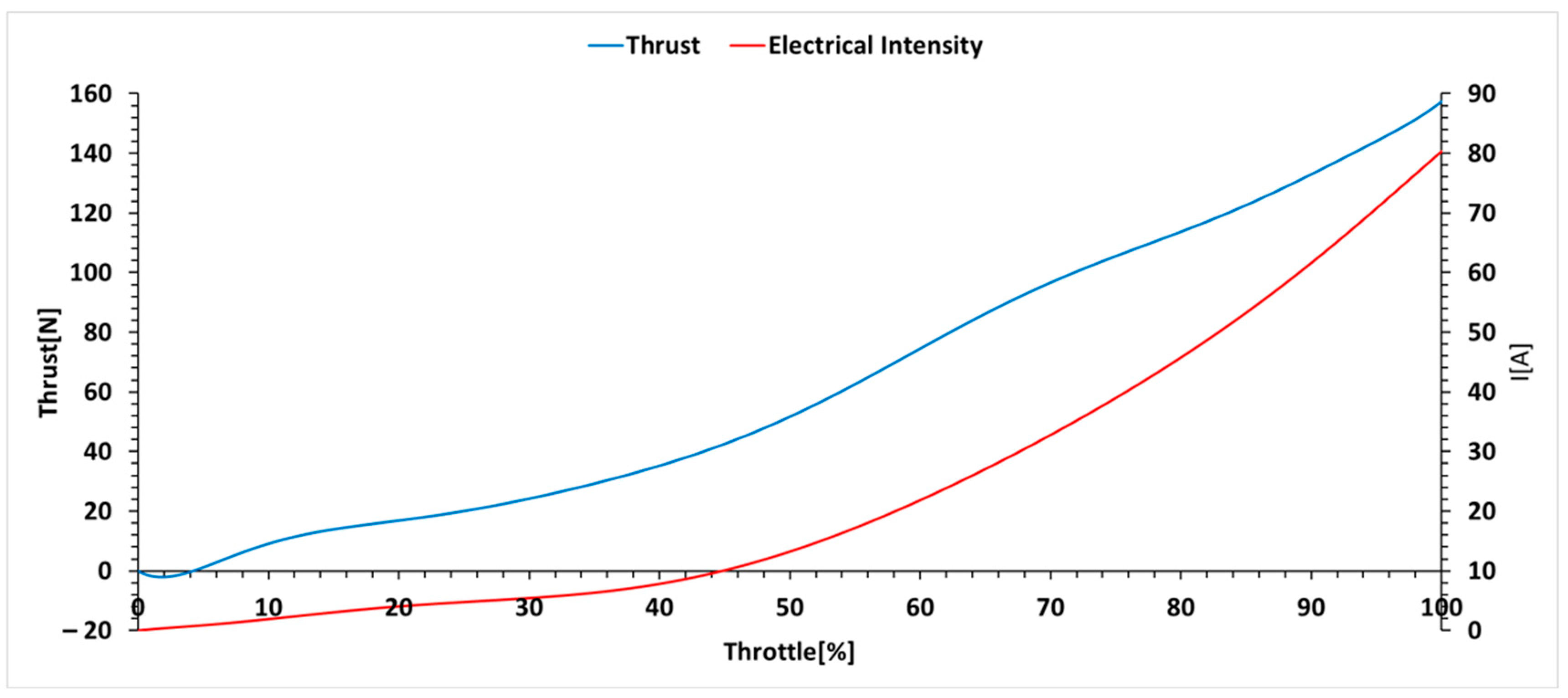
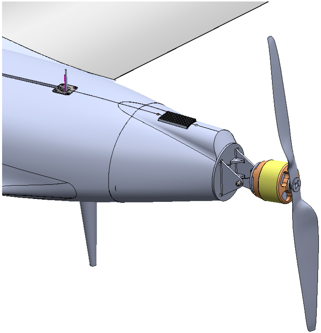
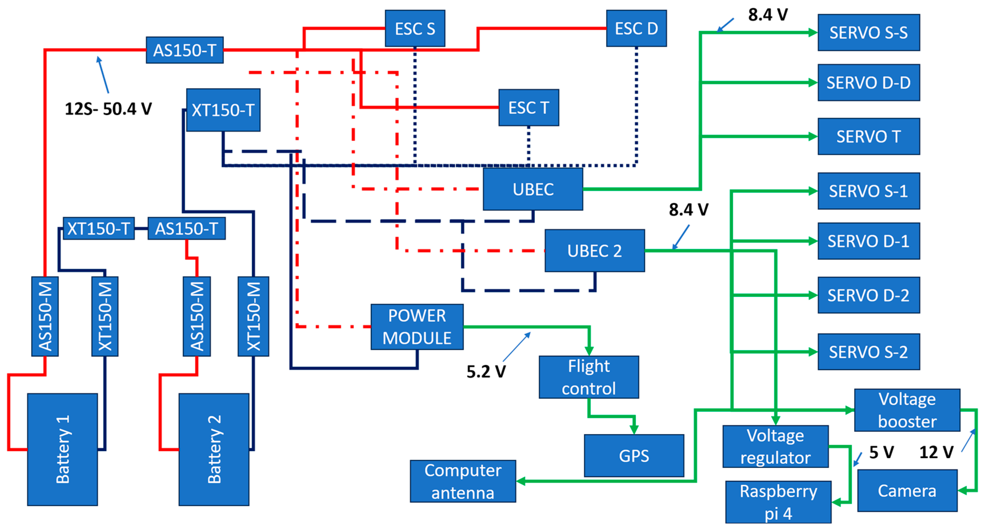
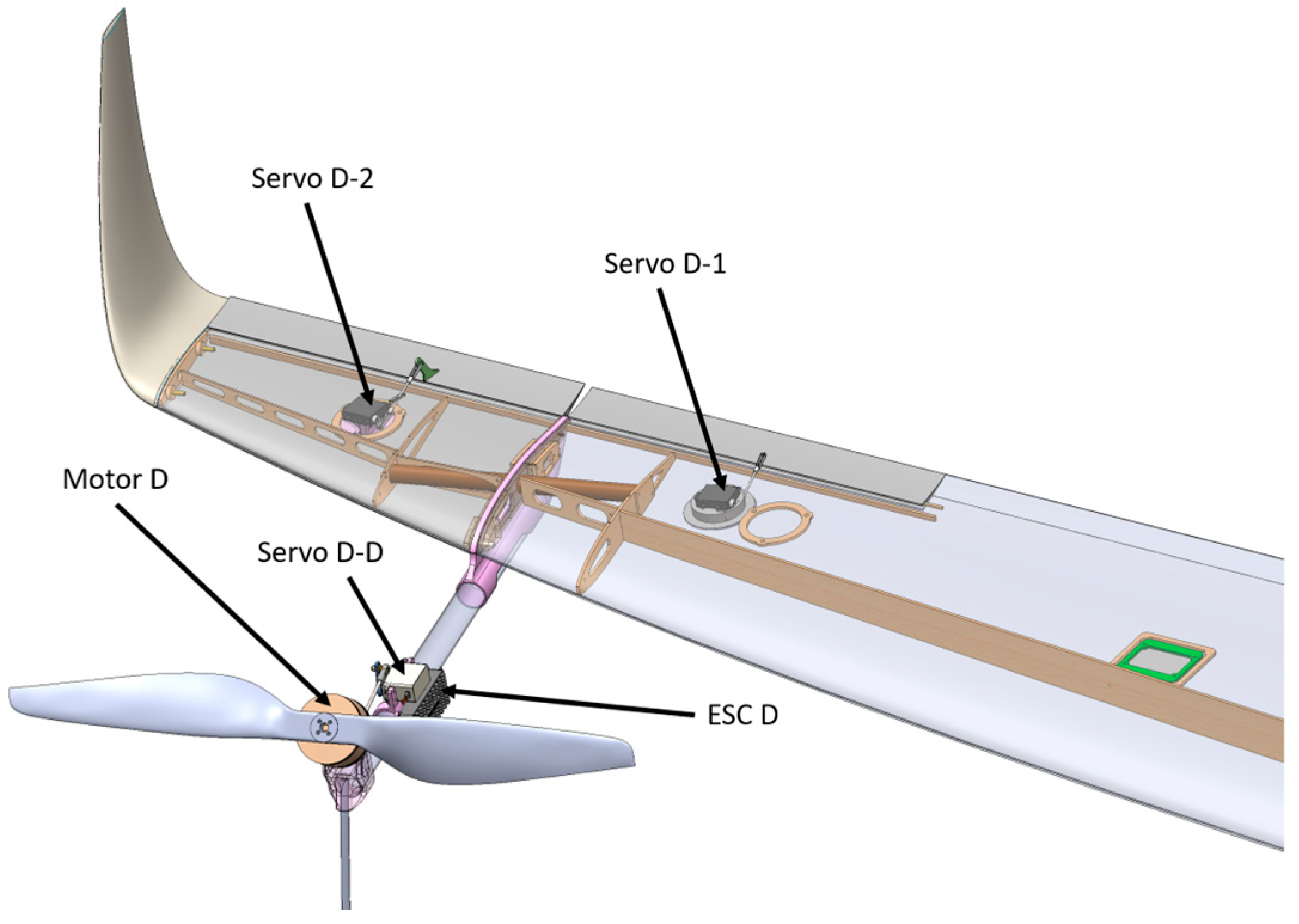
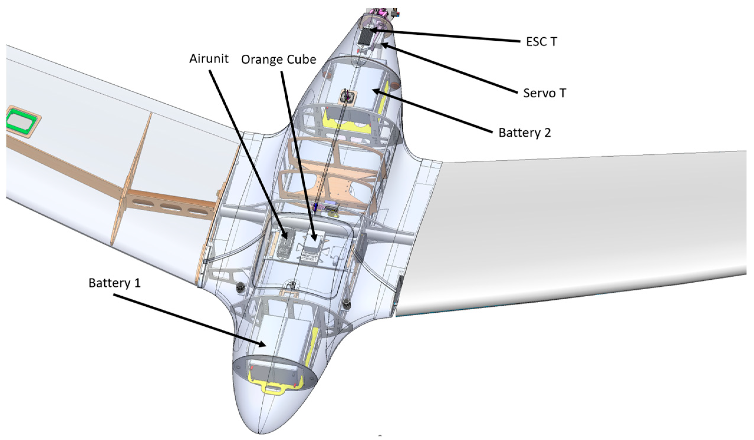
2.3. Drone’s Electrical System

The developed UAV platform has been equipped with electrical systems that are categorized as follows:
  • Propulsion system;
  • Command and control system;
  • Transmission system;
  • Control system for control surfaces;
  • Auxiliary systems.
The propulsion system consists of 3 MN805-S KV170 motors and 3 FLAME 100A 14S ESCs from an electronic perspective. The vectorization of these 3 motors around the Y-axis is achievable with the help of a BLS 5404H servo motor corresponding to each motor.
The chosen command and control system consists of an Orange Cube flight computer using Ardupilot software for flight control. It is connected to the Herelink v1.1 transmission system, and the control system for control surfaces is implemented using HV 5101 servo motors.
Auxiliary systems include the video camera system, acoustic system, and meteorological system. The video camera is powered by a UBEC (Ultimate Battery Eliminator Circuit) system and connected to the Herelink system. The acoustic system and the meteorological system are powered by a Raspberry Pi 4 computer and controlled by it.
The power supply voltage is 12S (50.4 V), and the energy source consists of 2 LiPo 6S 16,000 mAh batteries connected in series. The power source directly supplies power to the 3 ESCs and simultaneously to the UBEC and power modules.

3. Results

3.1. Performance and Design of the UAV

In Figure 3, the two coefficients are depicted as functions of the wing angle of attack. It can be observed that the lift coefficient reaches its maximum value at an angle of approximately 15°, while the drag coefficient increases with the angle of attack.
Therefore, using this simulator built in Matlab, it was determined that the maximum climb speed for the quad-rotor is 24.29 km/h, and the maximum forward speed reached 78.43 km/h. An angle of attack for the wing of approximately 4–5° was considered, and the pitch angle is not for the entire aircraft but is formed by the motor vectorization angle around the Y-axis. Additionally, motor control was limited to prevent excessive G-force from affecting the structure.
Altitude as a function of time for the tri-rotor and quad-rotor and the vectorization angle as a function of time for the tri-rotor and quad-rotor are very similar in the graphs, and the altitude is achieved and stabilized after approximately 200 s.
The parameters of interest are the thrust generated by each motor with the propeller and their respective power consumption. Figure 4 illustrates the curves of these two parameters.
Figure 5 depicts the thrust as a function of time for the tri-rotor and quad-rotor.
The maximum climbing speed of the tri-rotor was 24.55 km/h, and the maximum forward speed reached a value of 71.6 km/h, a lower value than in the case of the quad-rotor. It is noticeable that the thrust is lower for the tri-rotor, mainly due to its lower mass. A vectorization angle of 85° was imposed when reaching the required forward speed to ensure lift entirely from the wing to maintain stability control from the motors. The simulator did not include control systems for aileron, elevator, and rudder necessary for airplane-mode flight.
As final overall results, we have the following, presented in Table 2. Due to the weaker thrust, the completion time for the route is longer for the tri-rotor, but overall, the consumption is lower for the tri-rotor, even though the flight time is longer by over 1 min.
Therefore, in line with the project’s objectives to optimize the aerodynamics of the experimental model for achieving a flight autonomy of over 3 h and based on the results obtained from the calculations, the decision was made to opt for a tri-rotor system for the experimental model.
The design of the experimental model continued from this choice, with the focus on designing the structure that forms the wing, considering it as the most crucial aspect since it is a VTOL fixed-wing UAV. The XFLR5 program was used for wing design. In essence, the wing presented and used in the flight simulator developed in Matlab was retained, but now it has been optimized. The estimated final mass of the UAV is 15 kg.
The optimization involved dividing the wing into several sections where the MH45 airfoil profile was distributed, as seen in Table 3.
The wing is symmetric left–right, and the Y = 0 point represents the center of the wing. The offset represents the distance from the leading edge of the airfoil profile at the center of the wing to the leading edge of the next airfoil profile. The global parameters of the wing are as follows: wingspan: 4 m, wing area: 1.569 m2, mean aerodynamic chord: 409.26 mm, aspect ratio: 12.729, taper ratio: 0.097; it is noted that the winglet is included in the calculations.
Following the simulation from 0° to 16° (angle of attack), the aerodynamic coefficient performances shown in Figure 6 were obtained.
Figure 7 shows the displacement speeds based on the angle of attack.
In accordance with the project objective, the experimental model needed to achieve a cruising speed of approximately 50 km/h. Thus, as shown in the table presenting the wing simulation results, at an angle of attack of 6.5°, the required displacement speed to sustain flight for a mass of 15 kg is 50.32 km/h. Therefore, the designed wing ensures the aerodynamics for meeting the project objective. The lift coefficient at this angle is 0.784.
The drag at this angle is 0.027, meaning that the required thrust is 0.7043 N. Consequently, the MN805-S motor (T-Motor, Zhongshan, China) would have a consumption of 0.8335 A at a voltage of 12 S (50.4 V), equivalent to an electrical power consumption of 42 W. Thus, the energy required for this wing to achieve 3 h of autonomy is 2.65 Ah according to Equation (1).
F l i g h t t i m e = C a p a c i t y e n e r g y I n t e n s i t y c u r r e n t
where flight time—the duration of the flight [h]; energy capacity—the energy capacity from the batteries [Ah]; current intensity—the intensity of the consumed electric current [A].
A tailless aircraft configuration was chosen to achieve higher flight efficiency. The wing has a span of 3923 mm, the winglet size is 118 mm, and the fuselage length is 1264 mm. The selected tri-rotor VTOL system brings a distance of 3094.6 mm between the front motor axes, and the distance between the front motor axes and the M3 motor axis is 776.27 mm. Front motors are equipped with propellers 660 mm (26 inches) in diameter, while the M3 motor has a propeller 508 mm (20 inches) in diameter. Figure 8 illustrates the experimental model with component descriptions.
The experimental model is also equipped with winglets designed to reduce drag (by minimizing vortex intensity), thereby increasing flight autonomy. The fuselage of the experimental model is aerodynamically integrated with the fixed wing. Due to the VTOL system, a fixed landing gear was implemented, without wheels specifically for VTOL takeoff/landing, consisting of three components highlighted in Figure 8. As this is a tailless aircraft, there are no ailerons at the wingtips but elevons. These control surfaces are responsible for the roll and pitch movements of the aircraft. The elevon is divided into two components due to the mounting of the VTOL structure. The total control surface area of the elevon is 508.11 cm2 (measured on the upper surface).
The experimental model represents a category of hybrid fixed-wing UAV, meaning it incorporates both fixed-wing mechanics and a VTOL system that allows vertical takeoff/landing as well as slow-speed flight (below the necessary lift threshold) and hovering. This VTOL system offers the advantage of eliminating the ground infrastructure required for aircraft takeoff/landing. Figure 9 illustrates the chosen solutions for the propulsion system vectorization.
In the takeoff/landing phase, during slow-speed flight or hovering, the tri-rotor system is in the position shown in the figure below. For flight mechanics and balance, motor M1 rotates clockwise, and motor M2 rotates counterclockwise. Motors M1 and M2 are of the same type and will essentially operate at the same speeds, so the reactive torque of motor M1 is canceled out by the reactive torque of motor M2. However, being a tri-rotor system, motor M3 with clockwise rotation will generate a reactive torque counterclockwise, a torque that is not canceled out. Thus, the experimental model will have a counterclockwise yaw moment. The classical solution for a tri-rotor to cancel this reactive moment generated by the third motor is to vectorize motor 3 around the X-axis. However, in the case of this experimental model, an alternative solution will be chosen to cancel this reactive moment.
Figure 10 illustrates the rotation representation and motor notation.
Thus, the cancellation of the reactive moment generated by motor M3 will be achieved by vectorizing motor M2. The yaw balance is determined by the following equations:
M R 1 M R 2 = 0
M R 3 F 2 × cos θ 2 × 3094.6 2 = 0
where M R i —reactive moment of motor i [Nm]; F2—thrust generated by motor M2 [N]; θ 2 —tilt angle of motor M2 [°].
The distance of 3094.6 mm represents the separation between the axes of the front motors, and its half represents the moment arm generated by the vectorized component of motor M2. The consequence of using this method is that the elevons will have to counteract the moment given by the vectorization of this motor M2 (if the speed of movement is zero or very small, roll stabilization is done from the speed of motor M1), a roll moment, but this moment has a small value.
Using this VTOL vectorization system, a uniform and aerodynamically optimized transition from hover flight to cruise flight will be made by easy, gradual, and controlled vectorization of all three motors around the Y-axis. When cruise flight is achieved, then only motor M3 will be used, which will have the following position shown in Figure 11.
The flight equations that will yield the two accelerations on the X and Z axes are as follows:
F 1   ×   cos θ 1 + F 2   ×   cos θ 2 + F 3   ×   cos θ 3 R x = m a x
F 1   ×   sin θ 1 + F 2   ×   sin θ 2 + F 3   ×   s i n θ 3 R z + 0.5   ×   C L   ×   A   ×   V x 2   ×   ρ = m a z
F 1   ×   cos θ 1 + F 2   ×   cos θ 2 + F 3   ×   c o s ( θ 3 ) = m a x
where Fi—thrust of the i-th motor [N]; θ_i—tilt angle of the i-th motor [°]; m—total mass of the aircraft [kg]; ax—acceleration in the X direction of the aircraft [m/s2]; az—acceleration in the Z direction of the aircraft [m/s2]; Rx—drag in the X direction [N]; Rz—drag in the Z direction [N]; CL—aerodynamic coefficient of the wing; ρ—air density [kg/m3]; A—wing area [m2]; Vx—speed in the X direction [m/s].
It should be noted that during takeoff/landing, the tilt angles of the motors are 90° (parallel to the Z-axis of the aircraft), except for motor M2, which has a small tilt angle to cancel the reactive moment of motor M3. In the transition or at low speeds (below the required lift limit), the wing maintains its pitch angle, but the motors begin to be vectorized to decompose the thrust and thus have forward motion. When the wing provides the necessary lift for the aircraft, motors M1 and M2 are stopped, and motor M3 operates with a tilt angle of 0°. All control is performed by motor speeds and vectoring angles when the speed is zero or the wing does not provide the necessary lift, and when the lift is entirely provided by the wing, stability control is entirely handled by control surfaces, namely elevons. The drone was not designed to fly in rain or strong winds.

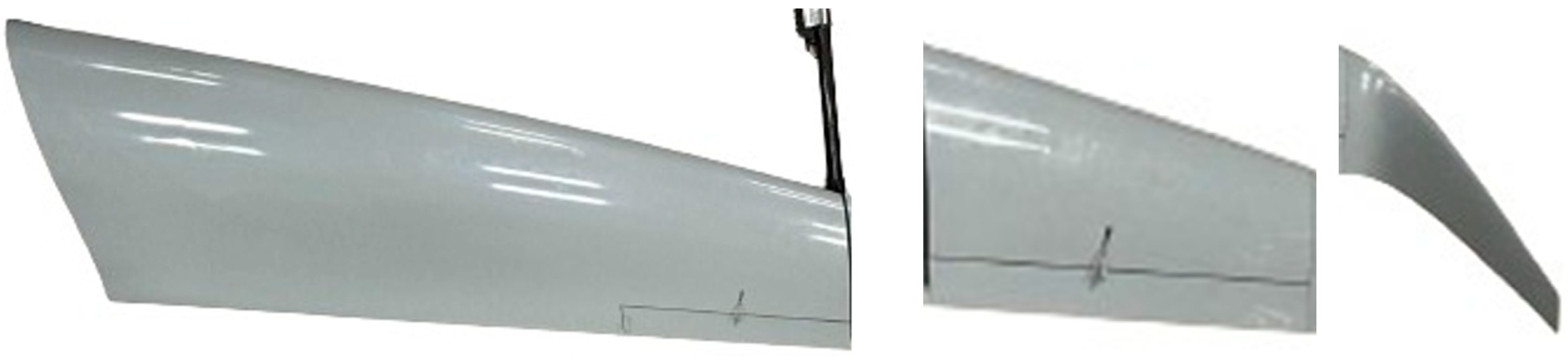
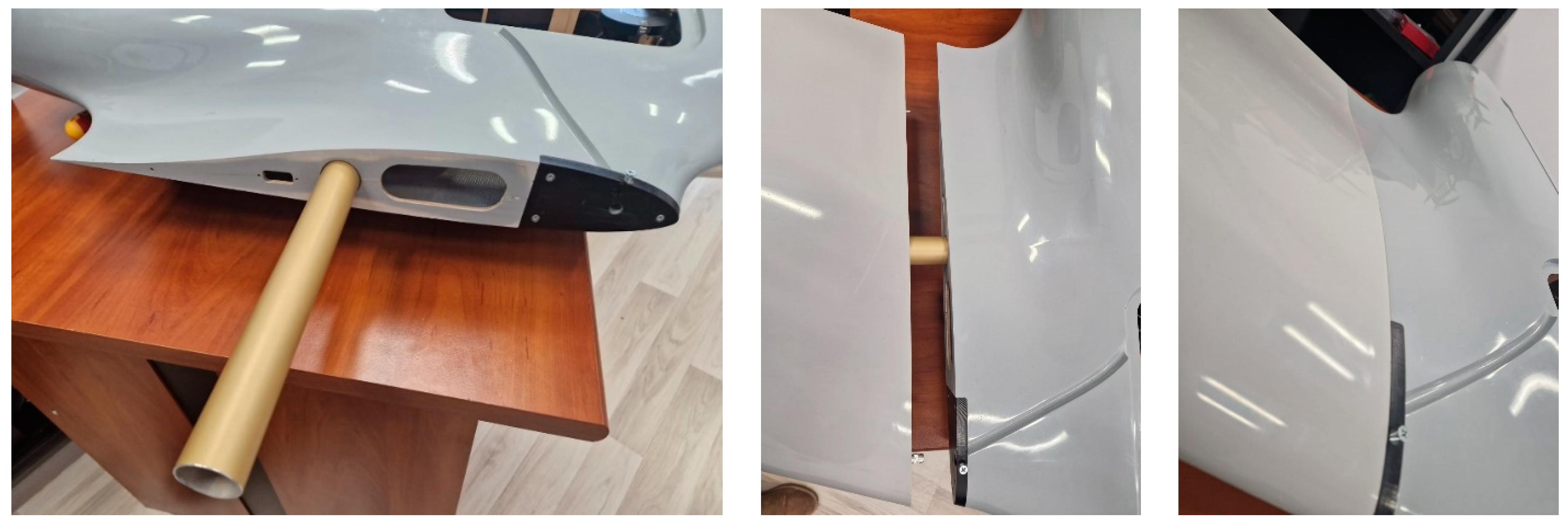
3.2. Results of Manufacturing the Experimental Model Structure

To create the central body structure of the drone, the process began with the creation of molds for the matrices. The mold for the central body of the drone was made using milling on computer numerical control (CNC) machines.
To achieve such a mold and its related structure, the following steps are followed: the mold is machined from easily milled materials HDF (high-density fiberboard); the finished surface is treated (in the case where the mold is made of wood, lacquer is applied to its surface); the mold is finished; a release agent is applied; gelcoat is applied (epoxy paint, polyurethane paint, etc.); the part is laminated (reinforcing materials and the polymeric matrix—a mixture of resin and hardener—are placed); after the polymer matrix has cured, the part is extracted from the mold.
After the milling of the model is complete, the areas are analyzed and manually finished using abrasive strips of appropriate fineness, as shown in Figure 12.
The molds for the aerostructure were created using the manual lay-up method at room temperature with the aid of a brush/roller [42]. As a result of the process, Figure 13 illustrates the completion of the fuselage mold. In this way, the molds that will facilitate the creation of the complex aerodynamic shapes of the fuselage and other components constituting the aerostructure were produced.
Further, in Figure 14, the creation of molds for the frontal and posterior components of the aerostructure is presented.
The next step is to create the load-bearing structure consisting of ribs, stringers, and other internal structural elements inside the fuselage and wing. These were made from lightweight plywood, as shown in Figure 15.
After the cutouts were complete, the assembly stage followed; it was accomplished by joining the pieces according to Figure 16 and permanently bonding them using an adhesive.
The final step to complete the fuselage, as shown in Figure 17, is to cover the internal structure with adhesive and then proceed with the other half of the covering.
The same construction process will be used for the other components, such as the central wing and the wingtip, as well as the winglet. The manufacturing process for these involves the “lay-up” method assisted by a vacuum.
The next step is to create molds for the sections that will constitute the wings of the experimental UAV model. Three molds were made for the wings according to the design: the main part of the wing, its extremity, and the winglet, as shown in Figure 18.
The manufacturing process for the three parts of the wings is presented further, as shown in Figure 19.
Figure 20 depicts the three main parts of the wing in their final configuration before assembly.
The next step is to assemble the three components of the wing, couple them with the fuselage, and attach the propulsion systems to the wings. The assembly process begins with the central part—the fuselage—to which the main part of the wing is attached, as shown in Figure 21.
Further, the joining of the main wing part with the wingtip and the support for the propulsion system is demonstrated. In Figure 22, the assembly of the wingtip with the propulsion system support arm is exemplified. This is achieved using an aluminum tube, secured with the aid of a clip, for the precise alignment of the planes.
The assembly of the winglet is carried out using two pins for guidance and alignment with the outer plane of the wingtip. Fixation is achieved with the help of a neodymium magnet, as illustrated in Figure 23.

3.3. Results of Manufacturing the Experimental Model Structure

In order to analyze the electrical installation, the electrical components are presented in Table 4, accompanied by brief descriptions and their respective masses.
The electrical system of the drone is depicted in Figure 24, illustrating the schematic diagram of the UAV’s electrical configuration.
The three ESCs are directly powered by the batteries, while other components require a lower voltage supply. Therefore, voltage step-up/step-down modules were employed. The S-S (left vectorization), D-D (right vectorization), and T (tail motor vectorization) servo motors are powered at 8.4 V through a UBEC module capable of delivering up to 25 A. The flight computer along with the GPS antenna is supplied at 5.2 V from the power module, and the servo motors controlling the control surfaces are also powered at 8.4 V, but from a different UBEC module. To power the video camera, which requires 12 V, a voltage booster module is placed between the camera and UBEC 2, raising the voltage from 8.4 V to 12 V.
The acoustic system along with the meteorological sensor needs to be powered at 5V, a voltage obtained by reducing the voltage from UBEC 2 from 8.4 V to 5 V using a voltage step-down module.
Figure 25 illustrates the positioning of electronic components in the UAV system. In this figure, the arrangement of the motors and their notation can be observed. UAV control is carried out through three methods, depending on the flight mode.
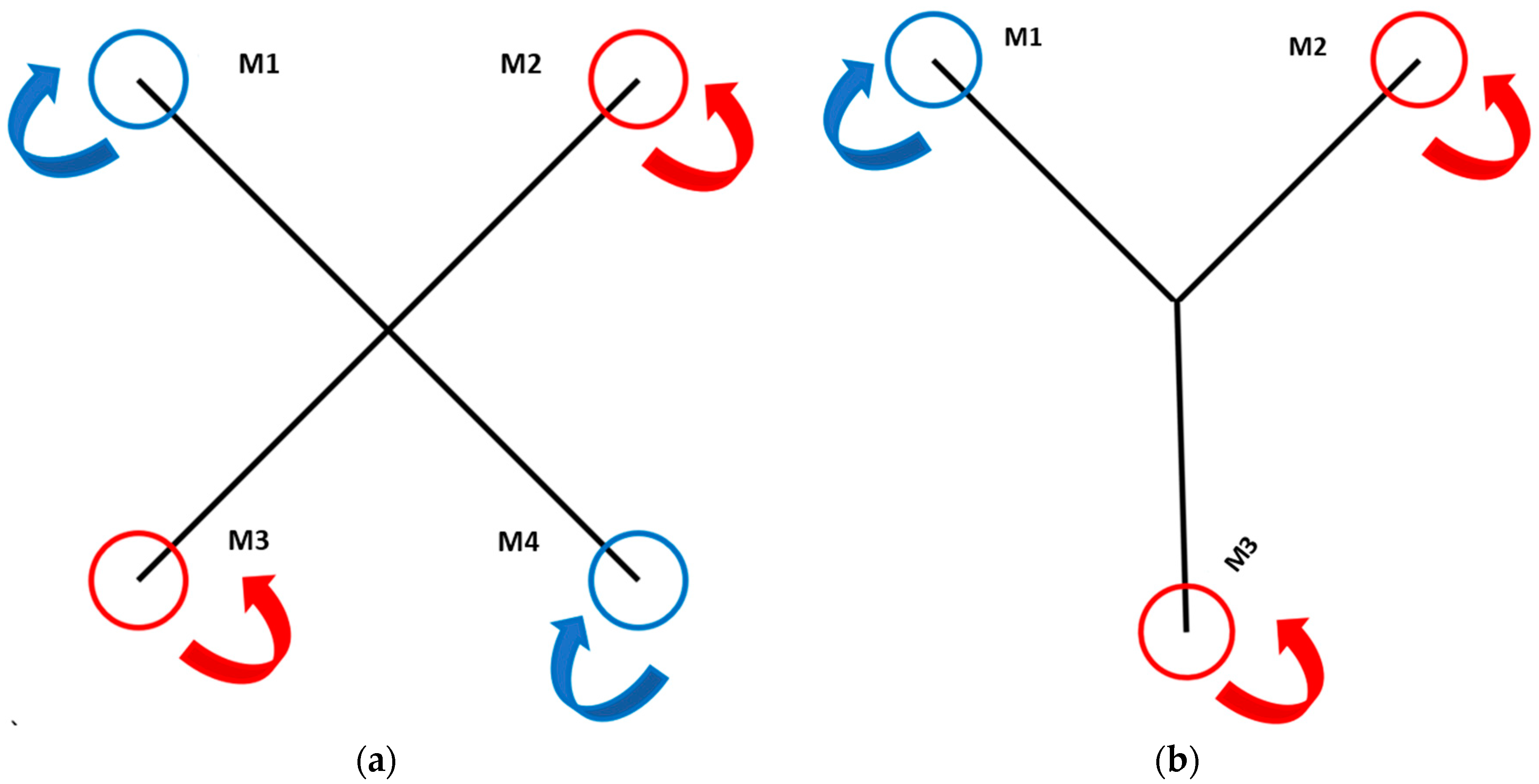
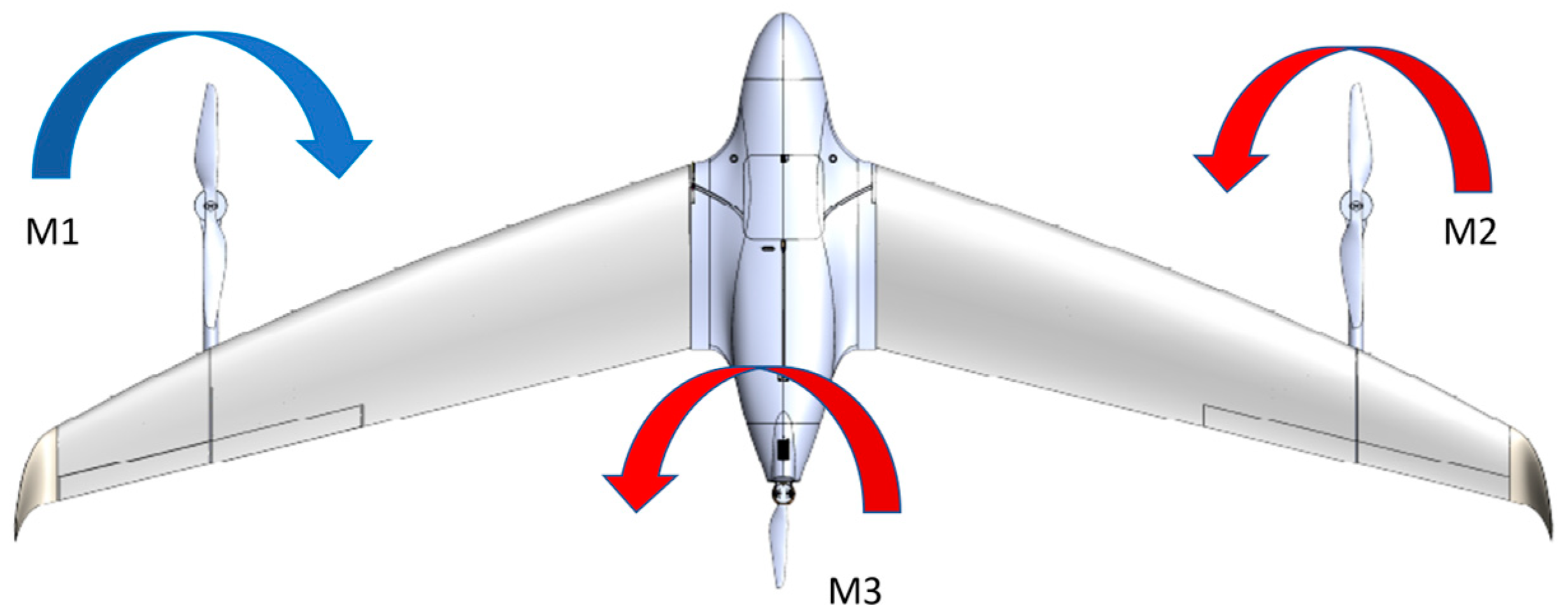
  • In VTOL flight mode (hovering): UAV control is achieved by adjusting the speed of the three motors, and roll stability is maintained through vectorization of the front motors.
  • In cruise mode: UAV control is performed by manipulating control surfaces and adjusting the speed of motor T.
  • In transition mode from VTOL to cruise: Control is managed through the speed of the three motors and their vectorization.
Figure 26 depicts the positioning of the D-D, D-2, and D-1 servo motors, as well as the D ESC. It is evident that all servo motors are placed near the control systems to minimize travel. Servo motors D-1, D-2, S-1, and S-2 control the elevons on the wings, while servo motors D-D, S-S, and T control the vectorization angle of each motor in the propulsion system.
In Figure 27, the fuselage is transparent to allow for a view of the positioning of central electronic components. Battery 1 is mounted in the frontal area of the fuselage, while battery 2 is positioned dorsally. Through their placement, the desired center of gravity of the UAV is adjusted. The Orange Cube flight computer and the Airunit transmission system are mounted side by side in the central area of the fuselage, with the flight computer being rigidly attached to the fuselage. Servo motor T and ESC T are also highlighted in the figure.
The video camera is mounted on the lower part of the fuselage, providing an unobstructed field of view, as depicted in Figure 28.

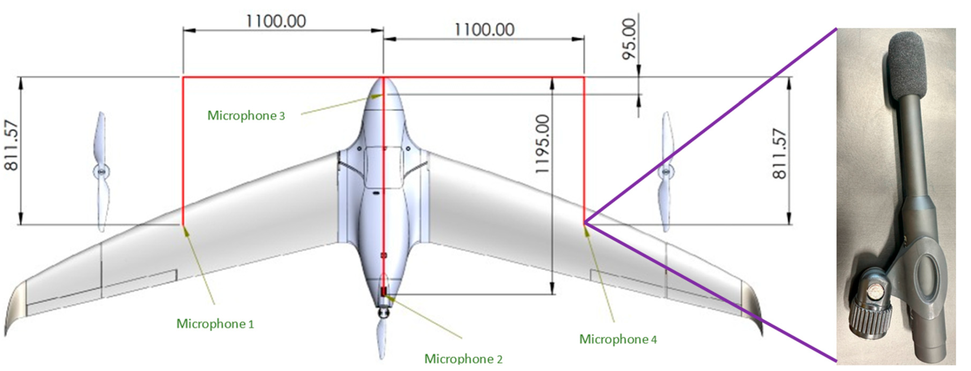
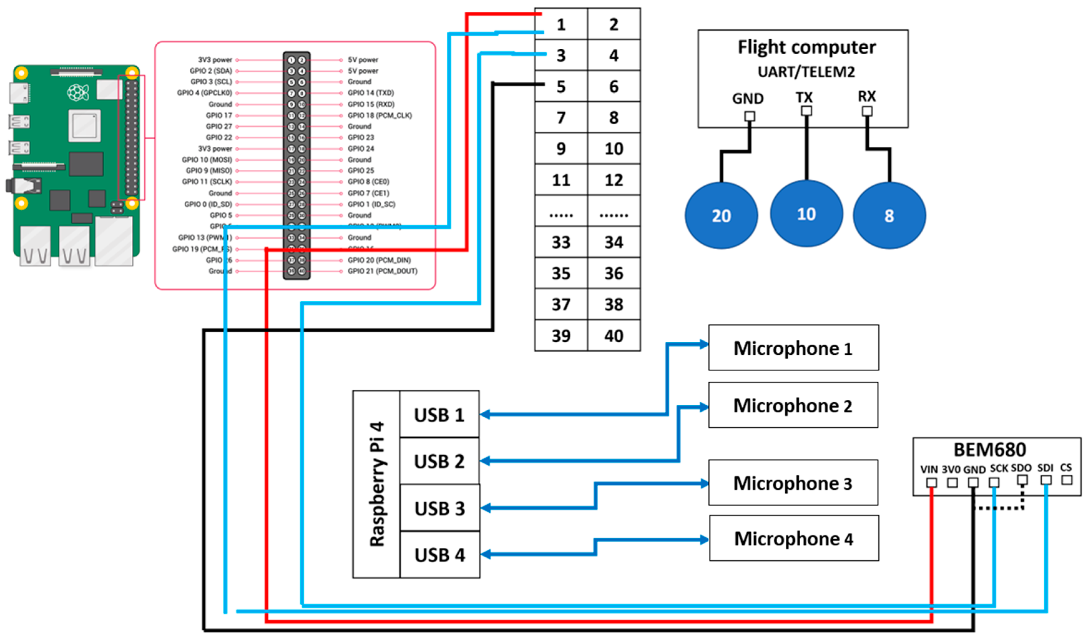
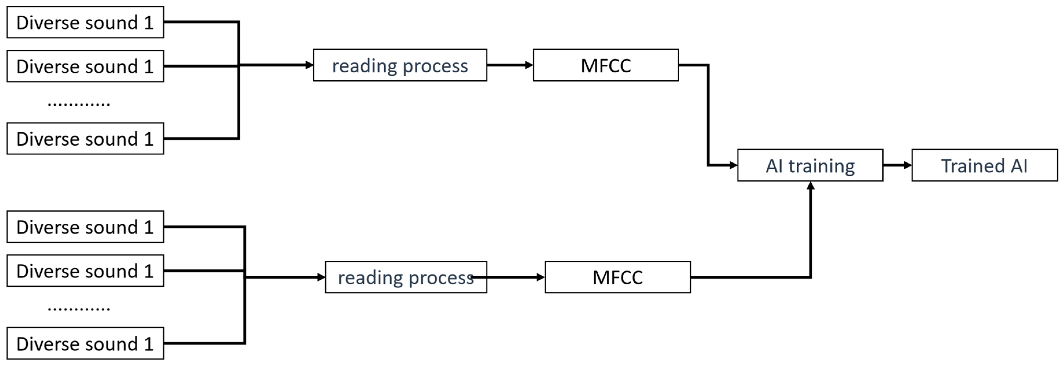
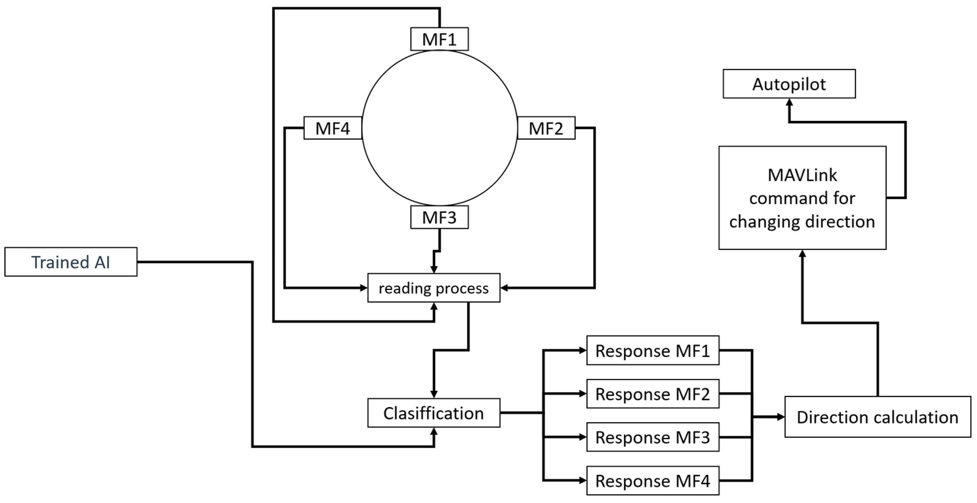
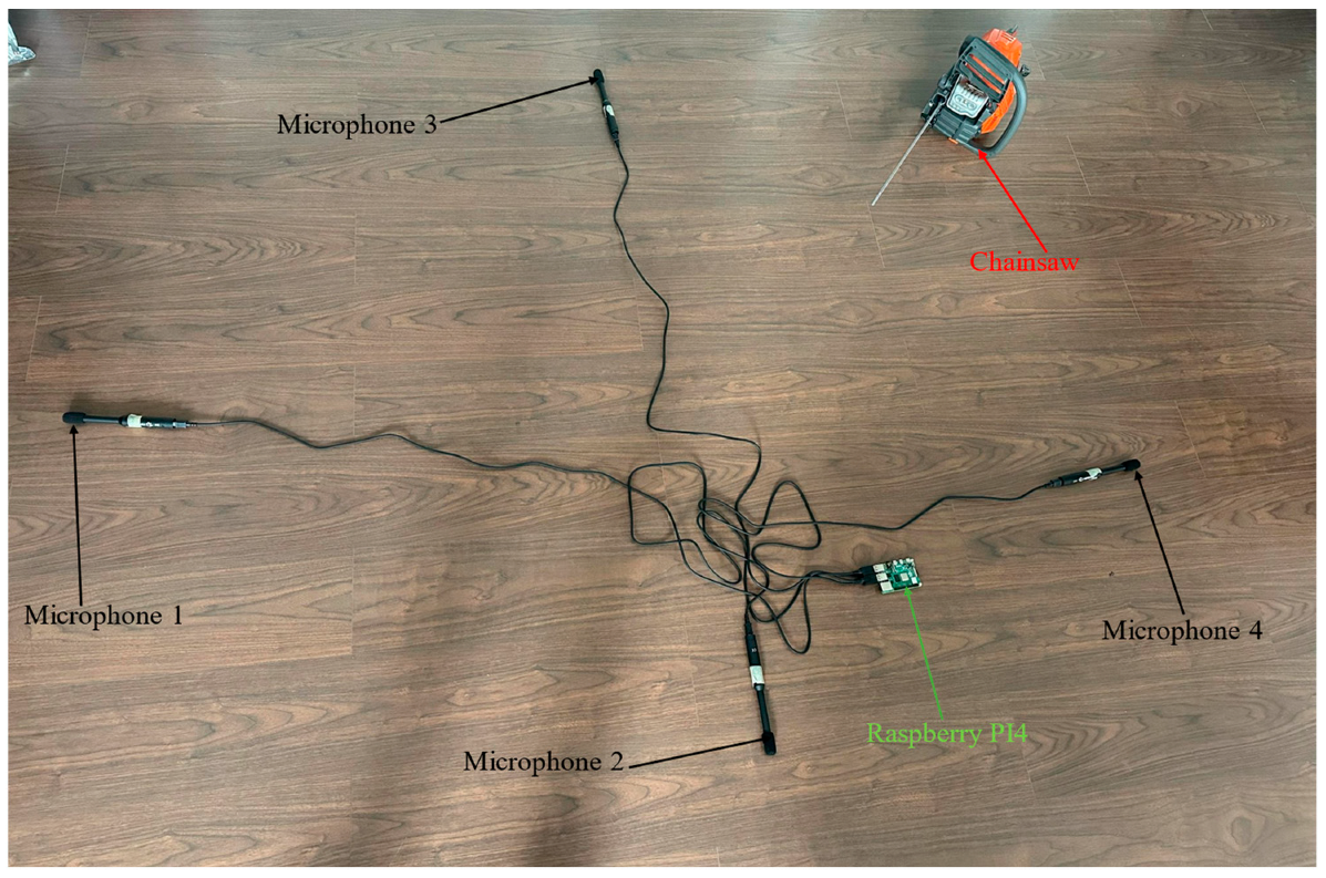
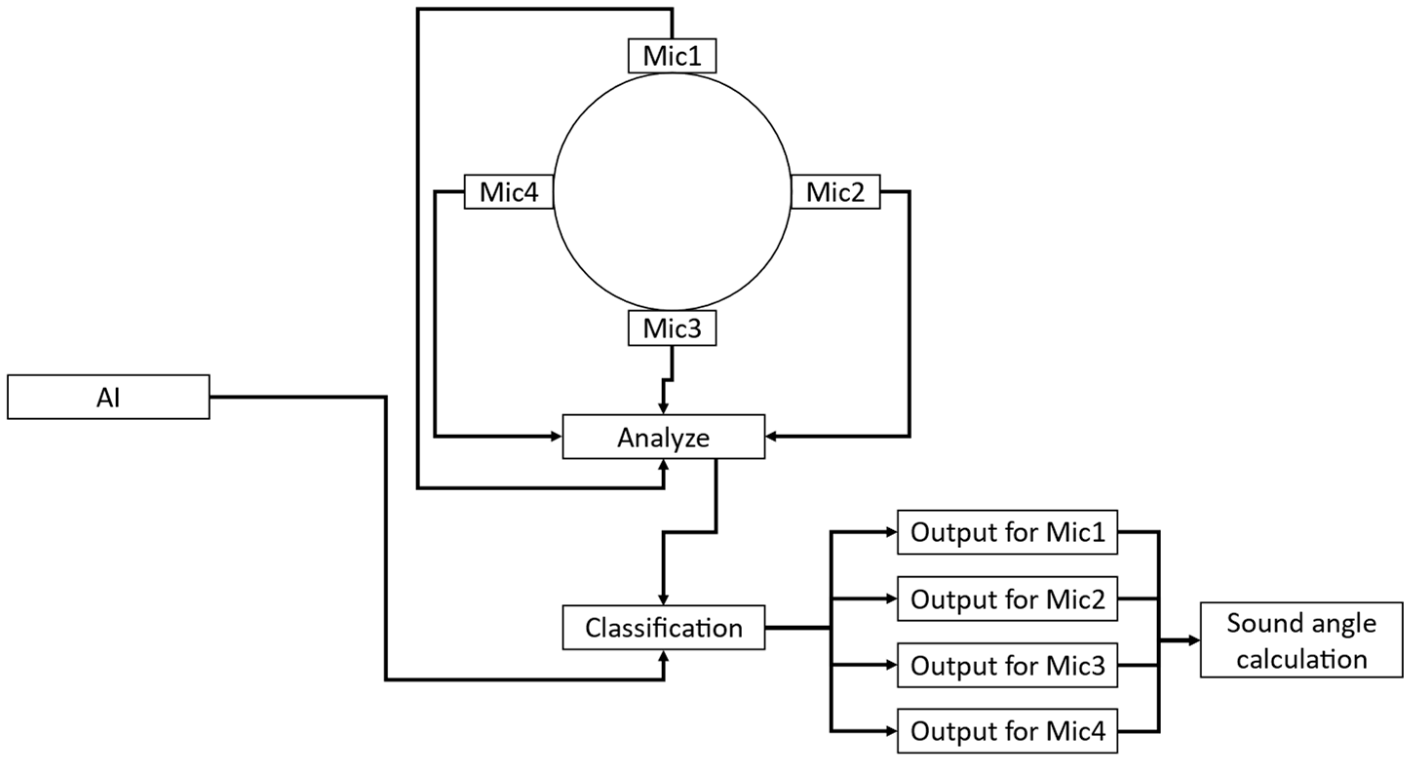
3.4. Acoustic System of the Drone

To fulfill the project’s objective, the UAV must be equipped with an acoustic system for the automatic detection and localization of the noise source (chainsaw) to verify the legality of tree cutting when the UAV flies over forests. Additionally, the UAV’s payload must include a meteorological sensor. Figure 29 presents the microphone positions.
The acoustic system, along with the meteorological sensor, is arranged according to the following electrical scheme in Figure 30.
The chosen data processing computer is a Raspberry Pi 4 powered by the UAV’s power circuit. It supplies power to and controls the sensors, namely the four microphones and the meteorological sensor. In the first stage, the Hifiberry measurement microphone, a measurement microphone, is designed with only one goal: linear frequency response [43]. The chosen meteorological sensor is the BME680. The meteorological sensor can record data about temperature, humidity, barometric pressure, and gases with volatile organic compounds (VOCs).
The connection between the acoustic computer and the flight computer is made according to the scheme, to establish UART communication between the two computers and send a Mavlink command to change the flight direction according to the calculated direction of the noise source within the acoustic system.
The developed software is divided into two equally important parts. The first part involves training an artificial intelligence using mel-frequency cepstral coefficients (MFCCs). The initial segment of the software reads a number of audio files, which are of two types. The first type of audio file encompasses various sounds, excluding specific sounds such as electric/thermal saws and chainsaws. To enhance the accuracy of artificial intelligence for diverse sounds, a sound resembling a power drill was chosen because its frequency spectrum closely resembles that of a chainsaw.
The second type of audio file pertains to specific sounds, such as those produced by saws and chainsaws. After reading these files, the results are transmitted to the MFCC feature. This initiates data pre-processing by enhancing the signal through a filter that emphasizes high frequencies. The resulting signal is then divided into a series of overlapping short frames. Each frame has an average duration of 30 ms and is analyzed individually. The next applied process is the fast Fourier transform, which converts the signal from the time domain to the frequency domain. The final result is represented by a set of coefficients that depict the short-term power spectrum of the sound in different frequency bands. In conclusion, MFCCs are popular in such applications because they capture the essential features of the audio signal while eliminating unnecessary details. The logical flow of this first part of the software is illustrated in Figure 31.
After the first part of the AI software is complete, the AI is fully trained and capable of recognizing the sound of tools used in illegal deforestation. The software proceeds to the second part. If the first part can be considered an education phase for the AI, the second part involves using the fully trained AI to recognize the specific sound at various instances and then instructing the autopilot to change the drone’s direction towards the detected sound.
The operational principle is as follows: The four microphones, positioned as shown in Figure 29 (0°, 90°, 180°, 270° relative to the front of the drone), record the surrounding sound and transmit it to the database where the sounds are classified by the trained AI. Once classified, the sounds can be of two types: diverse sounds or specific sounds. After identifying the type of sound, if it is diverse, the drone continues on its predefined path. If the sound is classified as specific, the microphone that recorded the sound is identified, and with the use of a mathematical algorithm, the angle from which the specific sound source is generated is calculated. With the help of a Mavlink command, the drone changes its flight direction towards the specific source. The logical flow is presented in Figure 32.
At the completion of the electronic components’ installation, the developed UAV appears as shown in Figure 33.
After the components were fabricated, they were weighed to estimate the total mass of the UAV (Table 5).
It can be observed that the total mass of the UAV is approximately 15 kg, as shown in Table 5, including the batteries, which aligns with the calculations from the UAV design.
In order to validate the acoustic system, the first step involved mitigating any potential errors; the training code for artificial intelligence analyzed over 20 h of chainsaw sounds and imposed the condition that any sound with an amplitude within 90% of that of the chainsaws be deemed false and labeled as nonspecific noise. Following the acoustic analysis of the UAV engines, an average amplitude of 44.24 was obtained, which corresponds to 85% of the minimum amplitude of the chainsaws.
The ground tests were conducted as described in Figure 34. The chainsaw, i.e., a commercial chainsaw with a sound power level of 116 dB, was placed at a different angle. Once the sound from the chainsaw was captured by the microphones, four wav files were saved in the Raspberry PI4, and then the AI analyzed the files based on the logical scheme shown in Figure 35.
The AI analyzes the sounds recorded by the microphones. As a result of the analysis, the sounds are classified as specific sounds (from a chainsaw) or not specific (from other sound sources). Once the sound is classified as an SS (specific sound), the algorithm moves forward with the calculation of the sound angle; otherwise, the algorithm ends with “No SS found”.

4. Conclusions

Following the research, an investigation and development of a fixed-wing VTOL UAV were conducted with the mission of identifying and locating a specific noise generated by a chainsaw to combat illegal logging. The experimental model, developed through its configuration, ensures a large flight autonomy and the capability of vertical takeoff and landing, eliminating the need for ground infrastructure for these operations. The UAV is equipped with an acoustic system that allows the identification of the chainsaw sound using AI on board a companion computer within the UAV, which automatically performs the identification using a prepared database. Subsequently, the direction from which the specific sound originates is identified, and a MAVLINK command is sent to change the direction to the flight computer.
Therefore, this paper presents the research and development of a UAV designed to combat illegal tree cutting, ensuring a large flight autonomy, good maneuverability, and ease of operation due to the innovative VTOL system. Additionally, an algorithm of the acoustic system, together with the presented hardware system, can identify and locate specific chainsaw sounds. The UAV then automatically moves above the noise source and takes pictures, and these visual pieces of information are verified by the relevant authorities.
As future directions for development, optimizing the acoustic system for improved precision and conducting UAV testing with the identification system over forests are recommended.

Author Contributions

Conceptualization, G.C. and T.F.F.; methodology, D.E.C.; software, T.F.F., M.D. (Madalin Dombrovschi) and V.A.; validation, D.E.C.; Investigation, M.D. (Marius Dima); writing—original draft preparation, G.C. and G.P.B.; writing—review and editing. All authors have read and agreed to the published version of the manuscript.

Funding

This research was carried out under the “Nucleu” Program, Grant No. 31N/2023, Project PN 23.12.03.01, funded by the Romanian Ministry of Research, Innovation and Digitization. The APC was also funded by the Romanian Ministry of Research, Innovation and Digitization through the “Nucleu” Program, Grant No. 31N/2023.

Data Availability Statement

All data are in the article.

Acknowledgments

This research was carried out under the PTE program PN-III-P2-2.1-PTE-2021-0369, contract number 101 PTE/2022-ENFORCING, funded by the Romanian Ministry of Research, Innovation and Digitization.

Conflicts of Interest

The authors declare no conflicts of interest.

References

  1. Shakoor, S.; Kaleem, Z.; Baig, M.I.; Chughtai, O.; Duong, T.Q.; Nguyen, L.D. Role of UAVs in Public Safety Communications: Energy Efficiency Perspective. IEEE Access 2019, 7, 140665–140679. [Google Scholar] [CrossRef]
  2. Adoni, W.Y.H.; Lorenz, S.; Fareedh, J.S.; Gloaguen, R.; Bussmann, M. Investigation of Autonomous Multi-UAV Systems for Target Detection in Distributed Environment: Current Developments and Open Challenges. Drones 2023, 7, 263. [Google Scholar] [CrossRef]
  3. Thiele, S.T.; Varley, N.; James, M.R. Thermal photogrammetric imaging: A new technique for monitoring dome eruptions. J. Volcanol. Geotherm. Res. 2017, 337, 140–145. [Google Scholar] [CrossRef]
  4. Caspari, G.; Sadykov, T.; Blochin, J.; Buess, M.; Nieberle, M.; Balz, T. Integrating Remote Sensing and Geophysics for Exploring Early Nomadic Funerary Architecture in the “Siberian Valley of the Kings”. Sensors 2019, 19, 3074. [Google Scholar] [CrossRef] [PubMed]
  5. Patel, M.; Bandopadhyay, A.; Ahmad, A. Collaborative Mapping of Archaeological Sites Using Multiple UAVs. In Proceedings of the Intelligent Autonomous Systems 16; Ang, M.H., Jr., Asama, H., Lin, W., Foong, S., Eds.; Lecture Notes in Networks and Systems; Springer International Publishing: Cham, Switzerland, 2022; pp. 54–70. [Google Scholar]
  6. Rejeb, A.; Abdollahi, A.; Rejeb, K.; Treiblmaier, H. Drones in agriculture: A review and bibliometric analysis. Comput. Electron. Agric. 2022, 198, 107017. [Google Scholar] [CrossRef]
  7. Goodrich, P.; Betancourt, O.; Arias, A.C.; Zohdi, T. Placement and drone flight path mapping of agricultural soil sensors using machine learning. Comput. Electron. Agric. 2023, 205, 107591. [Google Scholar] [CrossRef]
  8. Febria, J.; Dewi, C.; Mailoa, E. Comparison of Capacitated Vehicle Routing Problem Using Initial Route and Without Initial Route for Pharmaceuticals Distribution. In Proceedings of the 2021 2nd International Conference on Innovative and Creative Information Technology (ICITech), Salatiga, Indonesia, 23–25 September 2021; pp. 94–98. [Google Scholar]
  9. Loianno, G.; Kumar, V. Cooperative Transportation Using Small Quadrotors Using Monocular Vision and Inertial Sensing. IEEE Robot. Autom. Lett. 2018, 3, 680–687. [Google Scholar] [CrossRef]
  10. Menouar, H.; Guvenc, I.; Akkaya, K.; Uluagac, A.S.; Kadri, A.; Tuncer, A. UAV-Enabled Intelligent Transportation Systems for the Smart City: Applications and Challenges. IEEE Commun. Mag. 2017, 55, 22–28. [Google Scholar] [CrossRef]
  11. Stan, A.C. A decentralised control method for unknown environment exploration using Turtlebot 3 multi-robot system. In Proceedings of the 2022 14th International Conference on Electronics, Computers and Artificial Intelligence (ECAI), Ploiesti, Romania, 30 June–1 July 2022; pp. 1–6. [Google Scholar]
  12. Hafeez, A.; Tiwari, V.; Verma, V.K.; Ansari, A.S.; Husain, M.A.; Singh, S.; Khan, A.N. Crop Monitoring and Automatic Weed Detection using Drone. In Proceedings of the 2021 International Conference on Control, Automation, Power and Signal Processing (CAPS), Jabalpur, India, 10–12 December 2021; pp. 1–4. [Google Scholar]
  13. Anghelache, D.; Persu, C.; Dumitru, D.; Bălţatu, C. Intelligent Monitoring of Diseased Plants Using Drones. Ann. Univ. Craiova Agric. Mont. Cadastre Ser. 2021, 51, 146–151. [Google Scholar] [CrossRef]
  14. Supriya, C.; Murali Arthanari, P.; Kumaraperumal, R.; Sivamurugan, A. Optimization of Spray Fluid for Herbicide Application for Drones in Irrigated Maize (Zea mays L.). Agric. Food Sci. 2021, 33, 137–145. [Google Scholar] [CrossRef]
  15. Brahmanand, P.; Singh, A.K. Precision Irrigation Water Management-Current Status, Scope and Challenges. Indian J. Fertil. 2022, 18, 372–380. [Google Scholar]
  16. Stone, Z.; Parker, K.A. Unmanned aerial vehicle (UAV) activity elicits little to no response from New Zealand forest birds during wildlife monitoring. Notornis 2022, 69, 25–119. [Google Scholar]
  17. Ivanova, S.; Prosekov, A.; Kaledin, A. A Survey on Monitoring of Wild Animals during Fires Using Drones. Fire 2022, 5, 60. [Google Scholar] [CrossRef]
  18. Ecke, S.; Dempewolf, J.; Frey, J.; Schwaller, A.; Endres, E.; Klemmt, H.J.; Tiede, D.; Seifert, T. UAV-based forest health monitoring: A systematic review. Remote Sens. 2022, 14, 3205. [Google Scholar] [CrossRef]
  19. Cillero Castro, C.; Dominguez Gomez, J.A.; Delgado Martin, J.; Hinojo Sanchez, B.A.; Cereijo Arango, J.L.; Cheda Tuya, F.A.; Diaz-Varela, R. An UAV and Satellite Multispectral Data Approach to Monitor Water Quality in Small Reservoirs. Remote Sens. 2020, 12, 1514. [Google Scholar] [CrossRef]
  20. Hemamalini, R.R.; Vinodhini, R.; Shanthini, B.; Partheeban, P.; Charumathy, M.; Cornelius, K. Air quality monitoring and forecasting using smart drones and recurrent neural network for sustainable development in Chennai city. Sustain. Cities Soc. 2022, 85, 104077. [Google Scholar] [CrossRef]
  21. Heupel, M.R.; Lédée, E.J.; Simpfendorfer, C.A. Telemetry reveals spatial separation of co-occurring reef sharks. Mar. Ecol. Prog. Ser. 2018, 589, 179–192. [Google Scholar] [CrossRef]
  22. Taddia, Y.; Pellegrinelli, A.; Corbau, C.; Franchi, G.; Staver, L.W.; Stevenson, J.C.; Nardin, W. High-resolution monitoring of tidal systems using UAV: A case study on Poplar Island, MD (USA). Remote Sens. 2021, 13, 1364. [Google Scholar] [CrossRef]
  23. Casana, J.; Laugier, E.J.; Hill, A.C.; Reese, K.M.; Ferwerda, C.; McCoy, M.D.; Ladefoged, T. Exploring archaeological landscapes using drone-acquired lidar: Case studies from Hawaii, Colorado, and New Hampshire, USA. J. Archaeol. Sci. Rep. 2021, 39, 103133. [Google Scholar] [CrossRef]
  24. Roiha, J.; Heinaro, E.; Holopainen, M. The Hidden Cairns—A Case Study of Drone-Based ALS as an Archaeological Site Survey Method. Remote Sens. 2021, 13, 2010. [Google Scholar] [CrossRef]
  25. Nath, N.D.; Cheng, C.S.; Behzadan, A.H. Drone mapping of damage information in GPS-Denied disaster sites. Adv. Eng. Inform. 2022, 51, 101450. [Google Scholar] [CrossRef]
  26. Daud, S.M.S.M.; Yusof, M.Y.P.M.; Heo, C.C.; Khoo, L.S.; Singh, M.K.C.; Mahmood, M.S.; Nawawi, H. Applications of drone in disaster management: A scoping review. Sci. Justice 2022, 62, 30–42. [Google Scholar] [CrossRef] [PubMed]
  27. Munawar, H.S.; Hammad, A.W.; Waller, S.T. Disaster Region Coverage Using Drones: Maximum Area Coverage and Minimum Resource Utilisation. Drones 2022, 6, 96. [Google Scholar] [CrossRef]
  28. Munawar, H.S.; Gharineiat, Z.; Akram, J.; Imran Khan, S. A Framework for Burnt Area Mapping and Evacuation Problem Using Aerial Imagery Analysis. Fire 2022, 5, 122. [Google Scholar] [CrossRef]
  29. Telli, K.; Kraa, O.; Himeur, Y.; Ouamane, A.; Boumehraz, M.; Atalla, S.; Mansoor, W. A Comprehensive Review of Recent Research Trends on Unmanned Aerial Vehicles (UAVs). Systems 2023, 11, 400. [Google Scholar] [CrossRef]
  30. Wang, H.; Sun, W.; Zhao, C.; Zhang, S.; Han, J. Dynamic Modeling and Control for Tilt-Rotor UAV Based on 3D Flow Field Transient CFD. Drones 2022, 6, 338. [Google Scholar] [CrossRef]
  31. Wang, Y.; Zhou, Y.; Lin, C. Modeling and control for the mode transition of a novel tilt-wing UAV. Aerosp. Sci. Technol. 2019, 91, 593–606. [Google Scholar] [CrossRef]
  32. Li, W.; Hsu, C.-Y. GeoAI for Large-Scale Image Analysis and Machine Vision: Recent Progress of Artificial Intelligence in Geography. ISPRS Int. J. Geo-Inf. 2022, 11, 385. [Google Scholar] [CrossRef]
  33. Oguntoye, K.S.; Laflamme, S.; Sturgill, R.; Eisenmann, D.J. Review of Artificial Intelligence Applications for Virtual Sensing of Underground Utilities. Sensors 2023, 23, 4367. [Google Scholar] [CrossRef]
  34. Zinno, R.; Haghshenas, S.S.; Guido, G.; Rashvand, K.; Vitale, A.; Sarhadi, A. The State of the Art of Artificial Intelligence Approaches and New Technologies in Structural Health Monitoring of Bridges. Appl. Sci. 2023, 13, 97. [Google Scholar] [CrossRef]
  35. Fumio Machida, Ermeson Andrade, Modeling and Analysis of Deforestation Prevention by Uncrewed Aerial Vehicles-based monitoring systems. Environ. Model. Softw. 2022, 158, 105540. [CrossRef]
  36. Ibraheem, M.K.I.; Mohamed, M.B.; Fakhfakh, A. Forest Defender Fusion System for Early Detection of Forest Fires. Computers 2024, 13, 36. [Google Scholar] [CrossRef]
  37. Paneque-Gálvez, J.; McCall, M.K.; Napoletano, B.M.; Wich, S.A.; Koh, L.P. Small Drones for Community-Based Forest Monitoring: An Assessment of Their Feasibility and Potential in Tropical Areas. Forests 2014, 5, 1481–1507. [Google Scholar] [CrossRef]
  38. Torres, V.A.; Jaimes, B.R.; Ribeiro, E.S.; Braga, M.T.; Shiguemori, E.H.; Velho, H.F.; Torres, L.C.B.; Braga, A.P. Combined weightless neural network FPGA architecture for deforestation surveillance and visual navigation of UAVs. Eng. Appl. Artif. Intell. 2020, 87, 103227. [Google Scholar] [CrossRef]
  39. Lopez-Sanchez, I.; Moreno-Valenzuela, J. PID control of quadrotor UAVs: A survey. Annu. Rev. Control 2023, 56, 100900. [Google Scholar] [CrossRef]
  40. Ozkan, D.; Gok, M.S.; Karaoglanli, A.C. Carbon Fiber Reinforced Polymer (CFRP) Composite Materials, Their Characteristic Properties, Industrial Application Areas and Their Machinability. In Engineering Design Applications III: Structures, Materials and Processes; Springer: Cham, Switzerland, 2020. [Google Scholar] [CrossRef]
  41. Chowdhury, N.; Faysal, G.M.; Islam, T.; Rahman, H.; Yeasmin, F. A Study on Mechanical Properties of Carbon Fiber Reinforced Polymer Composite. In Proceedings of the International Conference on Materials, Energy, Environment, and Engineering, Dhaka, Bangladesh, 29–30 November 2020. [Google Scholar]
  42. Available online: https://www.skyfilabs.com/project-ideas/fabrication-of-glass-hybrid-fiber-epoxy-composite-material-using-hand-layup-mathod (accessed on 1 March 2024).
  43. Available online: https://www.hifiberry.com/blog/measurement-microphones/ (accessed on 1 March 2024).
Figure 1. Primitive conceptual model of the UAV.
Inventions 09 00039 g001
Figure 2. Graphic representation for explaining the control matrix for motors: (a) quad-copter and (b) tri-copter.
Inventions 09 00039 g002
Figure 3. Lift coefficient and drag coefficient as a function of the angle of attack.
Inventions 09 00039 g003
Figure 4. Thrust and motor power consumption as a function of percentage throttle.
Inventions 09 00039 g004
Figure 5. Thrust as a function of time for tri-rotor and quad-rotor.
Inventions 09 00039 g005
Figure 6. Lift coefficient and drag coefficient as a function of the angle of attack before and after optimization.
Inventions 09 00039 g006
Figure 7. Variation in flight speed as a function of angle of attack.
Inventions 09 00039 g007
Figure 8. Dimensions and measurements on the experimental model.
Inventions 09 00039 g008
Figure 9. Presentation of the vectorization system within the tail motor (a) and presentation of the vectorization system at one of the front motors (b).
Inventions 09 00039 g009
Figure 10. CAD design and motor notation with their rotation.
Inventions 09 00039 g010
Figure 11. Position of motor M3 during cruise flight.
Inventions 09 00039 g011
Figure 12. (a) Intermediary stages for the mold creation process. (b) Final molds for the aerostructure.
Inventions 09 00039 g012
Figure 13. (a) Mold for molds. (b) Upper semi-structure. (c) Lower semi-structure.
Inventions 09 00039 g013
Figure 14. Mold and molds. (a) Front part of the fuselage. (b) Rear part of the fuselage.
Inventions 09 00039 g014
Figure 15. Cutting out the elements that will constitute the interior structure.
Inventions 09 00039 g015
Figure 16. (a) Three-dimensional model; (b) physical model for the interior structure; (c) fuselage and assembly of the structure envelope.
Inventions 09 00039 g016
Figure 17. Three-dimensional and physical model of the fuselage skin.
Inventions 09 00039 g017
Figure 18. Molds for the three sections of the wing.
Inventions 09 00039 g018
Figure 19. Manufacturing process of the three sections.
Inventions 09 00039 g019
Figure 20. The three parts of the wing in the final version.
Inventions 09 00039 g020
Figure 21. Wing–fuselage assembly.
Inventions 09 00039 g021
Figure 22. Wing tip assembly—propulsion system support arm.
Inventions 09 00039 g022
Figure 23. Winglet assembly—wing tip.
Inventions 09 00039 g023
Figure 24. Electrical diagram of the UAV.
Inventions 09 00039 g024
Figure 25. Placement of electronic components.
Inventions 09 00039 g025
Figure 26. Placement of equipment at the wingtip.
Inventions 09 00039 g026
Figure 27. Placement of electrical equipment in the fuselage.
Inventions 09 00039 g027
Figure 28. Placement of the video camera.
Inventions 09 00039 g028
Figure 29. Placement of microphones on the UAV and the microphone.
Inventions 09 00039 g029
Figure 30. Electrical diagram of the acoustic system.
Inventions 09 00039 g030
Figure 31. Logical structure of artificial intelligence (AI) training.
Inventions 09 00039 g031
Figure 32. Logical structure of the entire software.
Inventions 09 00039 g032
Figure 33. Overview image of the developed UAV.
Inventions 09 00039 g033
Figure 34. The ground tests.
Inventions 09 00039 g034
Figure 35. Logical scheme for ground tests.
Inventions 09 00039 g035
Table 1. Comparisons between the requirements of the 3- and 4-rotor systems.
Tri-Rotor SystemQuad-Rotor System
  • Does not require an additional frame for attaching the motors, considering that the third rotor is integrated into the tail of the aircraft.
  • The system can be integrated into the UAV structure, minimizing the negative impact on aerodynamics.
  • Estimated UAV mass: 15 Kg.
  • Requires an additional frame for at least 2 rotors.
  • The negative effect of increased drag is significantly higher compared to the tri-rotor due to the additional support frame required for rotor attachment.
  • An estimated additional mass of 3 Kg compared to the tri-rotor system (motor, propeller, ESC (electronic speed controller), structural supports, etc.).
  • Estimated UAV mass: 18 Kg.
Table 2. Comparative performance for the tri-rotor and quad-rotor models.
Tri-Rotor SystemQuad-Rotor System
Route Completion Time: 18.28 min
Energy Consumption Ah: 1.6582″
Route Completion Time: 17.17 min
Energy Consumption Ah: 1.8272″
Table 3. Procedure optimization of the wing.
Distant Y [mm]Chord Length [mm]Offset [mm]Dihedral Angle [°]Twist Angle [°]
0615.5000
250500115.500
11433904300−0.5
195020081530−1
199018086060−1
2030160910900
2280601067.5 2
Table 4. Electrical components of the UAV.
Equipment TypeDescriptionMass [g]
MN805-S KV170Voltage: 6-12S, maximum power: 4000 W625
FLAME 100A 14SContinuous maximum current: 100 A; voltage: 6-14S139
Servo motor BLS-5404HVoltage: 4.8–8.4 V; torque at 8.4 V: 50.9 kg·cm; speed at 8.4 V: 0.11 s/60°; current: 9.1 A at 8.4 V77.5
Servo motor HV-5101Voltage: 4.8–8.4 V; torque at 8.4 V: 6.8 kg·cm; speed at 8.4 V: 0.10 s/60°; current: 0.645 A at 8.4 V18
Orange CubeAutopilot73
Herelink v1.1Encrypted transmission system; range: 20 km; resolution: full HD; frequency: 2.4 GH95
Hobbywing UBEC 25AInput: 3S–18S; output: 5.2/6/7.4/8.4 V; current: 25 A.74
HOLYBRO Power Module-PM06 V2-14S Power ModuleOutput: 5 V; input: 2S–14S; current: 60 A24
Raspberry Pi 4For acoustic system control and reading meteorological sensor
BME680Meteorological sensor for temperature, humidity, barometric pressure, and VOC (volatile organic compound) gas3
ZR10 Video cameraVoltage: 3–4 S; 10× optical zoom (30× hybrid zoom); resolution: 2 k; control: S.bus/PPM/UART/UDP; video output: Ethernet; power consumption: 3 W with 3-axis GIMBAL381
HERE3+ GPS AntennaFor GPS signal51.8
Table 5. Component mass.
NameMass [g]NumberTotal Mass [g]
Winglet + semi-wing368.52737
Wing135122702
Fuselage2247.312247.3
Landing gear27.2381.6
Electronics100011000
Motor62531875
Propeller1103330
ESC1393417
Vectorization servo773231
Control surface servo18472
Video camera3811381
Acoustic system5001500
Flight controller (FC)73173
Airunit95195
Front motor mounting system334.61334.6
Dorsal motor mounting system1941194
Battery220024400
Total15,670.5
Disclaimer/Publisher’s Note: The statements, opinions and data contained in all publications are solely those of the individual author(s) and contributor(s) and not of MDPI and/or the editor(s). MDPI and/or the editor(s) disclaim responsibility for any injury to people or property resulting from any ideas, methods, instructions or products referred to in the content.

