Article

Analysis of a Newly Developed Afterburner System Employing Hydrogen–Methane Blends

National Research and Development Institute for Gas Turbines COMOTI, 220D Iuliu Maniu, 061126 Bucharest, Romania
*
Authors to whom correspondence should be addressed.
Inventions 2024, 9(4), 74; https://doi.org/10.3390/inventions9040074
Submission received: 18 June 2024 / Revised: 5 July 2024 / Accepted: 8 July 2024 / Published: 11 July 2024
(This article belongs to the Special Issue Thermodynamic and Technical Analysis for Sustainability (Volume 3))

Abstract

:
A considerable number of Combined Heat and Power (CHP) systems continue to depend on fossil fuels like oil and natural gas, contributing to significant environmental pollution and the release of greenhouse gases. Two V-gutter flame holder prototypes (P1 and P2) with the same expansion angle, fueled with pure hydrogen (100% H2) or hydrogen–methane mixtures (60% H2 + 40% CH4, 80% H2 + 20% CH4), intended for use in cogeneration applications, have been designed, manufactured, and tested. Throughout the tests, the concentrations of CO2, CO, and NO in the flue gas were monitored, and particle image velocimetry (PIV) measurements were performed. The CO, CO2, respectively, and NO emissions gradually decreased as the percentage of H2 in the fuel mixture increased. The NO emissions were significantly lower in the case of prototype P2 in comparison with prototype P1 in all measurement points for all used fuel mixtures. The shortest recirculation zone was observed for P1, where the axial velocity reaches a negative peak of approximately 12 m/s at roughly 50 mm downstream of the edge of the flame holder, and the recirculation region spans about 90 mm. In comparison, the P2 prototype has a length of the recirculation region span of about 100 mm with a negative peak of approximately 14 m/s. The data reveal high gradients in flow velocity near the flow separation point, which gradually smooth out with increasing downstream distance. Despite their similar design, P2 consistently performs better across all measured velocity components. This improvement can be attributed to the larger fuel injection holes, which enhance fuel–air mixing and combustion stability. Additionally, the presence of side walls directing the flow around the flame stabilizer further aids in maintaining a stable combustion process.

1. Introduction

In recent years, the urgency surrounding climate change and fuel sustainability has reached unprecedented levels, resonating across every corner of the globe. Thus, the imperative to transition towards renewable fuels and optimize power and propulsion systems emerges as a beacon of hope amidst the climate crisis. Hydrogen is renowned for its cleanliness as a fuel, emitting only water vapors and releasing energy when it is used in combustion, making it a carbon-free energy carrier; thus, the process has no byproducts that are harmful to the environment. As a clean fuel, hydrogen plays a pivotal role in reducing greenhouse gas emissions, offering a sustainable alternative to conventional fossil fuels. Bluff-body configurations are commonly employed to stabilize flames for gas turbines, aircraft engines, and industrial applications. While these configurations offer the advantage of creating a recirculation zone behind the bluff body, facilitating stable combustion, they also introduce challenges. The presence of the bluff body can induce disruptions in the flow field and combustion instabilities, particularly unstable vortex shedding. Consequently, a thorough understanding of the physical mechanisms governing flame stabilization and blow-off processes is imperative, especially in premixed combustion systems operating under highly turbulent conditions. Blended hydrocarbon/hydrogen fuels have emerged as an attractive solution to decrease emission levels while increasing the performance efficiency of the combustors compared to conventional hydrocarbon fuels. Blended hydrocarbons and hydrogen systems, often discussed in the context of Combined Heat and Power (CHP) applications, typically involve mixing hydrogen (H2) with various hydrocarbons to optimize performance and environmental benefits. Among these, methane (CH4) stands out as particularly beneficial. Methane, the primary component of natural gas, is abundant, inexpensive, and widely available. It has a high hydrogen-to-carbon ratio, leading to more efficient combustion with a lower carbon footprint compared to longer-chain hydrocarbons like ethane (C2H6), propane (C3H8), and butane (C4H10). When blended with hydrogen, methane’s combustion characteristics are enhanced, resulting in more stable and efficient energy production with reduced emissions of NOx and CO2. Additionally, methane’s compatibility with existing natural gas infrastructure makes it a cost-effective and practical solution for cleaner energy transitions. These attributes make methane a preferred choice over other hydrocarbons for optimizing the performance and environmental impact of CHP systems when blended with hydrogen. Research efforts, both through experimental and numerical studies, have extensively explored the dynamics of bluff-body flame stabilization. The impact of varying H2 and CH4 concentrations on ignition delay time and laminar flame speed during the combustion of CH4/H2 and multicomponent syngas mixtures is explored in the paper [1]. The study revealed that the reactivity of the mixture decreases with higher CH4 concentrations and increases with higher H2 concentrations. Increased H2 concentration accelerated the formation of OH, resulting in higher laminar flame speed and a shorter ignition delay time. The study also calculated CH4 and H2 concentrations at different pressures and equivalence ratios, demonstrating that CH4 consumption is slower at high pressures and reacts at different temperatures under varying equivalence ratios. Pio et al. [2] investigated the laminar burning velocity of various hydrogen–methane mixtures at low temperatures. The authors compared numerical findings obtained using detailed chemical kinetic mechanisms with experimental data from existing literature. Their study revealed that increasing the hydrogen concentration impacts chemical kinetics, particularly affecting the activation energy. They demonstrated that in mixtures containing hydrogen content exceeding 60%, the combustion regime primarily governed by methane is linked to limitations encountered during hydrogen formation, especially when hydrogen serves as an intermediate species in the decomposition chemical pathway of methane. Additionally, the authors conducted a sensitivity analysis study, revealing that reaction pathways responsible for producing significant species such as H are influenced by initial conditions, particularly at low temperatures. In another study, Salzano et al. [3] explored the impact of hydrogen concentration on the premixed flame structure of methane/hydrogen/air mixtures across various equivalence ratios and fuel compositions using both experimental and numerical approaches. Their findings revealed a significant reduction in the reaction zone thickness of methane/air mixtures upon the addition of hydrogen at 298 K. The authors demonstrated that the inclusion of hydrogen led to a higher sensitivity coefficient for the reaction H + O2 = O + OH, compared to pure mixtures under similar conditions, where a smaller sensitivity coefficient was observed. This suggests that the kinetic pathways and interactions between species play a crucial role in the combustion process. Finally, the authors highlighted that increasing the amount of carbon atoms in the fuel substantially reduces hydrogen concentration. Pourali et al. [4] revealed that introducing H2 into CH4/air combustion led to a more compact pre-flame and reaction region compared to combustion involving pure CH4. Chen et al. [5] determined that the most unstable H2/CH4/air flame occurs at approximately 80% H2 mole fraction. Experimental investigations also indicated that including CH4 improves energy conversion in microcombustors. The combustion characteristics of H2/CH4 fueled with/without a multi-bluff-body setting are presented in the paper [6]. The findings highlight the interplay of fuel properties, bluff-body placement, and structural parameters in the burning process and energy conversion. Some comprehensive conclusions are that the insertion of a bluff body significantly influences the flow field and alters the temperature and OH radical distribution. In another study, Leparoux et al. [7] present a numerical investigation of a hydrogen–air burner using large-eddy simulations (LES) with a focus on NOx prediction. The considered configuration is a two-staged combustor, similar to the well-known RQL (Rich–Quench–Lean) technology, supplied by a single coaxial injector characterized experimentally. Results show good agreement in predicting the main flow characteristics and the premixed flame position over different operating points and geometries for both frameworks. In contrast, NOx emissions are more sensitive; while the overall trend is well captured, the quantification is more scattered. An experimental study on the compact lean premixed flames stabilized on a bluff-body and swirl burner is performed by Zhang et al. [8]. Premixed CH4/H2/air mixtures are adopted with varied hydrogen fractions up to 80%. Results show that the flow straining near the flame root is dominant enough to induce root extinction and initiate the blow-off. With hydrogen addition, the flame root is strengthened due to the enhanced resistance to the strain. The increased burning velocity and temperature with hydrogen are also beneficial for flame stabilization. Recent studies by Vance et al. [9] and Jiménez et al. [10] have observed that the high diffusivity of hydrogen contributes to flame stabilization. In this study, stable flames are also achieved through the addition of H2. The objective is to investigate the impact of hydrogen on flame stabilization, particularly by examining its influence on flow-flame coupling. Stabilization regimes and pollutant emissions from partially premixed CH4/H2/air flames above a coaxial Dual Fuel Dual Swirl injector are investigated in a laboratory-scale combustor at atmospheric conditions with increasing hydrogen contents, as studied by Marragou et al. in the paper [11]. Flame stabilization regimes, CO, and NOx emissions are analyzed for different configurations of the injector and operating points. It has been found that NOx emissions remain low even for operations with pure hydrogen. Moreover, NOx emissions decrease when increasing the thermal power for a fixed equivalence ratio. In paper [12], the effects of hydrogen addition on the forced response of H2/CH4 flames are examined in a dual-nozzle swirl-stabilized combustor. The flame transfer function (FTF) is utilized to compare the forced response of the flames. The analysis revealed a decreasing trend in the local maximum gain values with increasing hydrogen content, and the frequency at which the FTF gain reached its local maximum shifted to higher frequencies. Additionally, hydrogen addition resulted in a decrease in the slope of the FTF phase. The study also demonstrated that hydrogen addition significantly extends the lean-burn limit of the flame. The burning velocity is an essential characteristic of premixed flames, which has already been studied for numerous fuel compositions, and it continues to be an important subject in recent experimental studies, e.g., for H2/CH4 blends [13] and pure H2 flames [14,15]. Hao Xia et al. [16] investigated the impact of thermal boundary conditions on the flashback of premixed 95% H2/5% CH4–air flames in a bluff-body swirl burner. The results show that the flashback characteristics are very sensitive to the bluff-body thermal boundary condition. At Twall = 350 K, the flashback is led by a large-scale swirling flame. However, when treating the bluff body as an adiabatic wall, the flashback is led by multiple small-scale flame bulges, and the circumferential motion of the lowest flame tip is negligible. Furthermore, it is found that as the boundary heat loss increases, the axial flashback speed decreases while the azimuthal flashback speed increases. The flashback of H2–CH4–air flames in the boundary layer of swirling flows has been investigated experimentally by Ebi et al. [17] in an optically accessible burner at elevated pressure and preheat temperature, and they found that the upstream propagation of flame can be led by flame bulges. Due to the inherent three-dimensional and transient nature of flame flashback, 3D parameter measurements and high-speed detecting devices are required, which leads to a significant challenge for experimental investigations of flashback. On the other hand, the large-eddy simulation (LES) approach is promising for understanding the flashback of swirling flames, given its lower computational cost than direct numerical simulation (DNS) and reasonable accuracy. Guo et al. [18] investigate the mechanism behind flame stability resulting from hydrogen enrichment. They conducted numerical investigations on swirled hydrogen-enriched CH4/air-lean premixed flames. The results demonstrated that hydrogen addition enhances the reactions H2 + OH = H + H2O and CH4 + H = CH3 + H2, thereby producing more radicals and consequently enhancing flame stability. Lean premixed CH4/H2/air flames with hydrogen fractions up to 80% were experimentally investigated as “V” to “M”-shaped swirl flames in paper [19]. Flow dynamics, such as mean and fluctuating velocity and flow straining, were also investigated using PIV measurement. The results show that with H2 addition, the outer recirculation zone first appeared downstream, where the corner flame started to propagate upstream; then, the recirculation zone expanded upward to form a stable “M” flame gradually. Emadi et al. [20] presented an experimental study on lean premixed combustion of methane and methane/hydrogen fuel mixtures (0%, 20%, and 40% hydrogen by volume) in a low-swirl burner at several chamber pressures. It was found that adding 20% hydrogen to the methane improves the blow-off limit by about 7%, while increasing the hydrogen content to 40% causes a 35% decrease in the blow-out limit and stabilizes the flame in a wider range of equivalence ratios. Halter et al. [21] investigated the impact of hydrogen addition on laminar and turbulent premixed methane/air flames. Three hydrogen enrichment volume fractions were tested (0%, 10%, and 20%). Adding hydrogen to the mixture increases the laminar burning velocity. Moreover, hydrogen addition causes a reduction in the dependence of the laminar burning velocity of the flame against stretch. It was also observed that the global height of the flame is largely affected by hydrogen addition and that the mean height of the flame decreases with hydrogen enrichment. Combustion instabilities were experimentally investigated for hydrogen-rich combustion by Nakaya et al. [22] in a model afterburner with two injectors installed at the end of a high-enthalpy wind tunnel. The combustion instabilities were studied using time-resolved measurements of near-infrared emissions from water molecules over 780 nm captured by a high-speed video camera. The transition behavior of the instabilities was observed in the recurrence plots in detail, indicating that the flame–vortex interaction excited the fourth harmonic mode of the thermoacoustic instability. Bluff-body stabilized premixed flames have been a subject of significant technological interest in practical combustion devices. An experimental study [23] focused on the anomalous blow-off of hydrogen-enriched flames. Flame shape evolution showed that, when the normal blow-off limit is approached, a flame narrows slightly above the flame base, forming a “neck”. The flame fronts merge at the “neck” location, and the flame breaks there, leading to complete flame extinction or leaving a very small flamelet near the flame holder. Later, Vance et al. [24] found that this necking of the flame front is a result of the local reduction in mass burning rates, causing flame merging and quenching of the thin flame tube formed. The structure of these flames at the necking location is found to be similar to tubular flames. It was also found that extinction stretch rates for tubular flames closely match values at the neck location of bluff-body flames of corresponding mixtures. This suggests that the excessive flame stretch is directly responsible for the blow-off of the studied Le ≤ 1 flame.
Even though there is extensive literature on Combined Heat and Power (CHP) systems and hydrogen blends, there are still gaps in the detailed effects of different H2/CH4 blends on bluff body combustion. Even though some studies have focused on the general performance of hydrogen methane blends during combustion, they rarely look at the influence of variations in the ratio of H2/CH4 blends on dynamics, stability, and emissions characteristics when used with bluff body configurations. This is an important gap because many studies have concentrated on hydrogen-enriched natural gas for its overall combustion properties without addressing intricate interactions and flame behaviors in bluff body scenarios. This void cannot be ignored as bluff body stabilization is widely used in industrial burners and gas turbines; hence, specific impacts of H2/CH4 blends can allow for optimized designs, resulting in better performance. Therefore, our research will attempt to bridge this gap by conducting a systematic study of different ratios of H2/CH4 blend”, contributing to a better understanding of fuel behavior within these applications. The present work continues the investigation of an afterburner system fueled with hydrogen/methane mixtures started in [24]. Using the same experimental testing rig with the same instrumentation (Figure 1) and fuel blends presented in [24], two new V-gutter flame holders (P1 and P2) with the same expansion angle (60 degrees) were developed and tested (Figure 2). The general dimensions of the newly designed flame holder are given in Figure 2. This research aims to design, manufacture, and conduct experiments on an afterburner system fueled with pure hydrogen as well as hydrogen–methane mixtures (80% by volume and 60% by volume, respectively) to assess flame stability. The final goal is the possibility of integrating this system into a cogeneration plant.

2. Materials and Methods

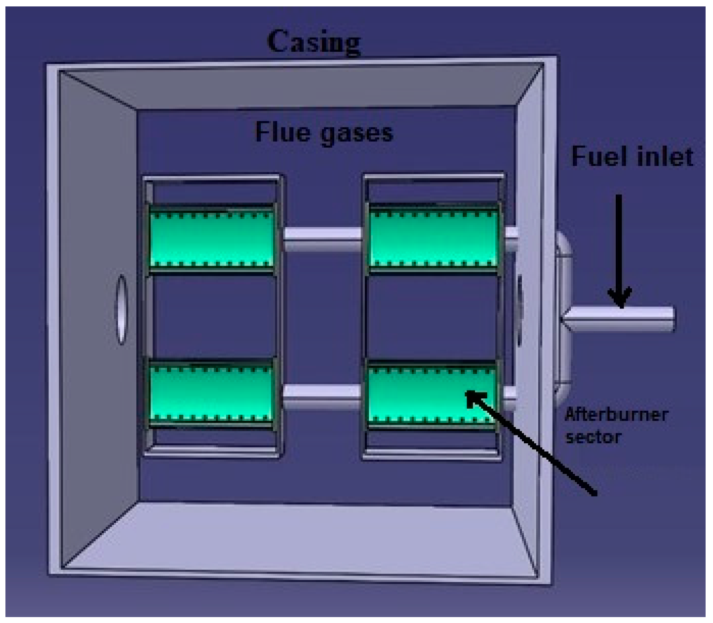
Test Rig Instrumentation and Afterburner Geometry

Figure 1a shows the diagram of the experimental test rig. The material used for manufacturing both prototypes, shown in Figure 2, was INCONEL 625. The afterburner assembly was installed downstream of a Garrett GTP 30-67 micro gas turbine engine (manufactured by Consolidated Diesel Electric CO, Stamford, CT, USA), within the exhaust gas flow, to supply burned gases to the post-combustion system. Using kerosene as fuel (mass flow: 15.9 kg/h), the gas turbine engine can achieve an outlet temperature of 600 K. During the combustion tests conducted at atmospheric pressure, the Garrett micro gas turbine operated consistently at an engine speed of 52,800 ± 200 rpm (idle, no load). The exhaust gas temperature and pressure at the afterburner inlet were maintained at 550 K and 1.05 bar absolute, respectively. Maintaining this consistent operating regime allowed for the identification of any potential discrepancies between the prototypes in terms of combustion stability, flame length, and geometric functionality. Moreover, on the gas turbine engine is installed a pipe designed to facilitate the seeding of PIV flow. This pipe facilitates the introduction of fine solid particles, specifically titanium oxide in this instance, into the flow to trace the fluid motion. Concurrently, a medium-intensity LASER beam emitted by a Nd:YAG double-pulsed LASER [25] illuminates the measurement zone, synchronously triggering two fast charge-coupled device (CCD) cameras to capture the resulting images. To achieve this, the LASER beam is directed through a Light Sheet Optics device, which converts it into a light sheet within the experimental zone. Along the axial direction downstream of the flame holder, a ruler was mounted where 5 distances for sampling the gas composition were marked. These 5 distances were set at 60 mm, 80 mm, 120 mm, 150 mm, and 200 mm. The reason why the maximum limit was 200 mm is to be in accordance with the size of the calibration plate for the PIV system, which is 200 mm square. The PIV system captured 10 series of 75 frames each to facilitate the computation of mean velocities. The number of frames per series was constrained by the memory resources of the CCD camera. Recording a larger number of frames would have necessitated data transfer from the cameras to the controlling computer, potentially impacting the speed of the data acquisition process and the coherence of the captured frames. The selection of these numbers was guided by recommendations outlined in the PIV system manual [26] and the information provided during the training session. The instrumentation movement is conducted using a threaded rod driven by an electric motor. For each recording, allocate a time of approximately 120 s. In Figure 1b, the totality of the used instruments can be seen as follows: 1. A type K thermocouple, connected through a PLC (programmable logical controller), used to monitor the flue gas temperature, Tmax = 1200 °C, accuracy ±1%, located in the center of the flame holder; 2. Horiba gas analyzer (model PG350), Kyoto, Japan; 3. The “V” flame holder; 4. Flame stabilizer housing; 5. Fuel supply pipe; 6. The ruler indicates the 5 monitoring points; 7. MRU gas analyzer. During the tests, for consistency, the gas temperature at the measuring point closest to the experimental model (60 mm) was kept at around 1000 °C.
The afterburner system includes a casing and flame holder assembly. The overall dimensions of the newly designed flame holders are illustrated in Figure 2a,b. Two new V-gutter flame holders with the same expansion angle of 60 degrees are tested to validate their proper functioning using 1. a fuel mixture composed of 60% H2 and 40% CH4, 2. a mixture composed of 80% H2 and 20% CH4, and 3. pure hydrogen (100% H2). The V-shaped flame holder features a concave wall, effectively forming an enclosure through which the fuel is delivered. The flame holder has 40 holes of Ø1 mm for Prototype 1 (Figure 2a) and respective Ø3 mm for Prototype 2 (Figure 2b), through which the fuel exits the enclosure and is injected into the gas flow. A total of 10 holes are situated on each lateral wall of the V-shaped fame holder, and 20 holes are situated on the concave wall enclosure. Additional walls have been placed on the sides of the flame stabilizer, with the role of directing the flow of combustion gases provided by the gas turbine engine (Garrett) around the V geometry of the flame stabilizer. The provided flow channel simultaneously allows the blending of combustion gases with fuel and, at the same time, the cooling of the flame holder wall due to the increased speed of the flow. On each additional wall are 15 holes of Ø2 mm. The testing facilities available in COMOTI’s Combustion Chamber Laboratory were modified to accommodate the testing of the afterburner system. The table below (Table 1) presents the ratio of primary fuel (Gas Turbine—GT) to secondary fuel (post-combustion) and the corresponding flue gas composition at the exit of the GT. As the hydrogen percentage in the fuel mixture increases, there is a noticeable decrease in the secondary fuel flow, leading to an increase in the primary fuel/secondary fuel ratio, as can be seen in Table 1. This trend can be attributed to hydrogen’s higher calorific value compared to methane. Thus, in order to obtain a temperature of 1000 °C at the first monitoring point (at 60 mm from the flame holder), a lower mass flow of secondary fuel is needed.
These hydrogen mixtures, as well as the pure hydrogen, were procured from the Linde Gas Romania special gases division. The mixtures were bottled at the Linde Czech/Prague factory and delivered in 50 L cylinders at a pressure of 200 bar. All fuel mixtures came with certificates of conformity. Throughout the combustion tests, the concentrations of CO, CO2, and NOx in the exhaust gas, as well as the exhaust gas temperature after the afterburner assembly, were continuously monitored.

3. Results and Discussion

3.1. Flue Gases Analysis

CO2 emissions levels and temperatures are illustrated in Figure 3a–c at five measurement points downstream of the flame holder for both tested prototypes and all three fuel blends. The green lines indicate the CO2 emissions coming from the Garrett gas turbine measured at a distance of 60 mm downstream of the flame holder before the afterburner installation was initiated for both tested prototypes. The CO2 concentration has a maximum peak at the first measurement point (60 mm), indicating the location where the combustion process occurred. Downstream, the CO2 concentration decreases with temperature, an effect of the exhaust jet mixing with the clean, cooler surrounding air. At the last measurement point (200 mm), the concentration reaches a level close to the Garrett gas microturbine CO2 level. It can be noticed that the higher the hydrogen gas contents in the fuel, the lower the CO2 concentration in the flue gases. The presence and activity of radicals in hydrogen–methane combustion significantly impact CO2 emissions, particularly through the pathways that influence the overall combustion efficiency and the formation of intermediate species. Although the global heat release rate reaches its peak at stoichiometric conditions, higher heat release occurs in the high-temperature zone under rich conditions due to the exothermic recombination of radicals. Radicals such as OH, H, and CH3 play a critical role in enhancing the combustion efficiency of hydrogen–methane mixtures. Efficient combustion leads to more complete oxidation of the fuel, thereby reducing the formation of partially oxidized intermediates and increasing CO2 production as a final product. The key reactions of radicals in hydrogen–methane combustion include:
OH + CO = CO2 + H
H + OH + M = H2O + M
H + CH3 (+M) = CH4 (+M),
OH + H2 = H + H2O,
2CH3 (+M) = C2H6 (+M)
where M is an inert that contributes to the reaction kinetics.
Reactions (1) and (2) become particularly significant in contributing to the total heat release. Reactions (3)–(5) gain increased importance in the heat release process, enhancing the reactions of oxidation for methane. Adding hydrogen to a methane fuel mixture increases the production of reactive radicals (H and OH), which accelerate the combustion reactions. This results in a higher combustion temperature and more efficient oxidation of hydrocarbons, thus increasing CO2 emissions relative to incomplete combustion products such as CO and unburned hydrocarbons (UHCs). The performance of the two tested prototypes was highly comparable. Across all three fuel blends utilized, the emissions showed slightly (Figure 3b,c) lower CO2 concentration levels for the P2 prototype. In Figure 3a, the CO2 emissions are slightly increased for the first two measurement points, at 60 mm and 80 mm distances from the flame holder for Prototype 1. The last three measurement points indicate similar values for CO2. In Figure 3b, the CO2 emissions also increased in the first two measurement points for Prototype 1, and the differences became less notable for the last three measurement points. In Figure 3c, there are no CO2 emissions due to the combustion process developed by the afterburner system because the fuel used is carbon-free. The exhaust gases from the Garret gas turbine are diluted with mostly water vapor. The CO2 content in P2 is consistently lower than in P1 at various distances from the flame holder. This is likely due to the presence of more H2 in the case of prototype P2. Thus, more hydrogen is converted to water vapor than methane, which is converted to carbon dioxide. The differences regarding the different values presented in the graphs are explained by the recirculation zone size for the P1 and P2 flame holders. This is due to the different fuel orifice sizes, which are described in Section 3.2, PIV Experiments.
The CO emissions and temperatures at the same five measuring points downstream of the flame holder for both tested prototypes and all three considered fuel compositions are depicted in Figure 4a–c. The green lines in these figures represent the CO emissions from the Garrett gas turbine measured 60 mm downstream of the flame holder before the afterburner installation was initiated. The flame holder plays a role in stabilizing the flame, which is essential for sustained combustion. Downstream of the flame holder, the combustion products and reaction intermediates continue to evolve. In the combustion process, CO is initially produced due to incomplete combustion or from the breakdown of hydrocarbons. As the combustion products move downstream, there are ongoing reactions, including CO oxidation (CO + OH → CO2 + H), which gradually reduces the concentration of CO. The CO emissions can be partly attributed to the shorter fuel residence time. This is influenced by the recirculation zone size for the P1 and P2 flame holders due to the different fuel orifice sizes, which are described in Section 3.2, PIV Experiments. Hydrogen-enriched fuel mixtures burn more efficiently due to hydrogen’s higher reactivity and adiabatic flame temperature compared to hydrocarbon fuels. Although high combustion temperatures (exceeding the CO2 dissociation threshold) typically enhance CO conversion, leading to more complete combustion and lower CO emissions, the competition for oxygen between the highly reactive hydrogen and hydrocarbons in the mixture can still result in increased CO emissions.
Essentially, hydrogen impedes the oxidation of hydrocarbons and their intermediates in oxygen-limited conditions (stoichiometric or rich mixtures). For P2, the maximum CO concentration is measured at 60 mm, which is the first measurement point near the flame holder, at all the fuel mixture concentrations. This observation may indicate a dynamic equilibrium between CO production and its subsequent oxidation. Beyond this equilibrium point, CO concentrations begin to decrease due to its efficient conversion to CO2 through the CO + OH reaction. When the hydrogen percentage in the fuel mixture increases, the flame lengths shorten because of hydrogen’s higher reactivity. This increased reactivity leads to a greater production of OH radicals, which accelerates combustion rates and shifts the reaction zone closer to the flame holder. The locally elevated temperatures near the flame holder, resulting from hydrogen combustion, further impact combustion phenomena.
These higher temperatures not only enhance the combustion process but also promote the dissociation of CO2 into CO and O. This dissociation is a critical factor for understanding and optimizing combustion processes, as it affects the overall efficiency and emission profiles of the combustion system. Consequently, the interplay between increased hydrogen reactivity, OH radical production, and local temperature changes must be carefully managed to optimize combustion performance and minimize undesirable emissions. The CO profile of the prototype P1 is shown slightly lower (Figure 4a). In Figure 4a, the maximum pick concentration is observed at 60 mm downstream of the flame holder. Further downstream, the concentration profile does not decrease but forms a Gaussian distribution. The same Gaussian distribution can be observed in Figure 4b, where the pick concentration is observed at 100 mm. Regarding Figure 4c, the CO concentration is under the Garret emission, and the variations of the values obtained in all the measurement points are due to the flow characteristics over the flame holder and the dilution of the exhaust gases with water vapors from the afterburner system.
The NO emissions and temperatures are presented in Figure 5a–c. NO is the primary nitrogen oxide emitted from most combustion sources. Various sources of literature data demonstrate a strong direct correlation between combustion temperatures and nitric oxide (NO) levels, with NO concentrations diminishing as temperatures decrease. This relationship underscores the critical importance of temperature regulation in combustion systems for effective NOx emission control. Understanding and mitigating NO formation in combustion processes necessitates the management of high-temperature conditions and the optimization of the air-to-fuel ratio. Heat loss from the flame occurs through radiation and convection mechanisms. As the volumetric participation of the hydrogen in the mixture increases, a smaller quantity of carbon atoms is present in the fuel. The carbon atoms are responsible for the radiation spectrum of the hydrocarbon flames.
Since carbon atoms are major contributors to the radiative heat loss in hydrocarbon flames, their reduction means less energy is lost through radiation. Hydrogen atoms, in contrast, do not significantly contribute to radiation. As a result, increasing the hydrogen content reduces radiative heat loss.
Despite the reduced radiative heat loss, flames with higher hydrogen content still exhibit higher temperatures. This occurs because hydrogen has a higher flame temperature than many hydrocarbons, including methane, a phenomenon confirmed by the much higher LHV (lower heating value) expressed in units of mass (LHVH2 = 120.1 MJ/kg and LHVCH4 = 50 MJ/kg). Hydrogen combustion produces water vapor (cp = 1.996 kJ/kg·K), which has a higher heat capacity than carbon dioxide (cp = 0.844 kJ/kg·K), resulting in more heat being absorbed by the combustion products. Additionally, hydrogen burns more quickly and completely, releasing energy more efficiently. These factors contribute to maintaining higher flame temperatures, especially in the nearby fuel injection ports, even as radiative heat loss diminishes. Consequently, hydrogen-enriched methane mixtures can achieve higher temperatures, improving combustion efficiency and performance.
Flame stretch, which arises in regions of the flow with high velocity gradients, will affect the combustion process significantly. As the stretch rate increases, the residence time of reactants in the reaction zone decreases, preventing the completion of chemical reactions. Consequently, the peak flame temperature drops, eventually leading to flame extinction. High exhaust gas temperatures facilitate the breakdown of nitrogen molecules and increase the number of molecular collisions with O2, resulting in the formation of nitrogen oxides.
NO concentrations were highest near the flame holder (at the first two measurement points) due to the high combustion temperatures. As expected, when the temperature probe was positioned further from the flame holder, the measured temperature decreased, resulting in lower NO levels being monitored. By the 200 mm measurement point, NO levels were comparable to those generated by the Garrett micro gas turbine.
Richer combustion in P2, due to larger fuel inlet holes, likely results in lower NOx emissions. In rich combustion zones, there is less oxygen available, which reduces the formation of NOx. This is because NOx formation is highly dependent on the availability of oxygen and the temperature of the flame front. The reduced oxygen in the richer P2 combustion environment leads to lower NOx production, as observed in our data.
Figure 5a–c also demonstrates a consistent reduction in NO emissions as the hydrogen content in the fuel mixture increased. The differences presented in the graphs are due to the recirculation zone size for the P1 and P2 flame holders due to the different fuel orifice sizes.

3.2. PIV Experiments

PIV (particle image velocimetry—LaVision GmbH, Göttingen, Germany) signals were emitted by the sheet beam produced by a double pulse Nd-YAG laser (Litron Nano L 200-15 (LaVision GmbH, Göttingen, Germany), λ = 532 nm [25]) and cylindrical lenses (f = −20 mm). Titanium oxide, with a mean diameter of approximately 0.2 μm, was used as the seeding particle. The stereo PIV velocity measurements utilized maximum laser power with a delay of 0.3689 ms between the laser pulse and the first camera trigger and a Δt = 15 µs interval between the triggers of the two cameras. Each camera had an exposure time of 100 µs, capturing images at a rate of 7.26 Hz. After achieving stable thermodynamic conditions, to track the fluid flow, the velocity downstream of the afterburner flame stabilizer was measured using particle image velocimetry. The experimental results are detailed as follows: the velocity components in these three directions are labeled V (axial), U (transversal), and W (spanwise). Using the software provided by LaVision GmbH, (Version ID: 10.2.1.90129) the images are processed, which includes the following operations: 1. Geometric mask; 2. PIV (particle image velocimetry); 3. Vector post-processing; 4. Vector statistic: vector field result; 5. Plot.
The velocity field is one of the most important parameters to describe motion in the combustion flow field. The recirculation zone length was defined as the axial point along the center of the bluff-body flame holder where the streamwise velocity transitions from negative to positive. The shape of the wake that forms downstream of the bluff body and serves as a recirculation and mixing zone is determined by the bluff body’s shape. This length responds to the sinusoidal velocity excitation, as illustrated in Figure 6a–c. The axial velocity is seen to be roughly uniform.
The shortest recirculation Figure 6a–c zone was observed for P1, where the axial velocity reaches a negative peak of approximately 12 m/s at roughly 50 mm downstream the edge of the flame holder, and the recirculation region spans about 90 mm. In comparison, the P2 prototype has a length of the recirculation region span of about 100 mm with a negative peak of approximately 14 m/s. It is well known that the length of the recirculation zone is affected by mean flow velocity and bluff body shape [27]. However, not only is the flame holder design relevant, but wall effects and blockage ratio are important because the side walls’ confinement effect considerably impacts the size and length of the recirculation zone. In general, the length of the recirculation zone becomes shorter with an increasing blockage ratio.
The velocity profiles averaged across the transverse direction are depicted in Figure 7, specifically at a distance of L = 60 mm downstream of the bluff body edge. The axial velocity profile (U-shaped streamwise velocity), as shown in Figure 7a–c, illustrates the region of recirculation characterized by negative values. The data in the graph reveal significant changes in axial velocity near the flow separation point, as evidenced by steep gradients in the velocity profiles of both P1 and P2. These steep gradients indicate rapid changes in velocity over a short distance, which are prominent near the bluff body. As we move downstream, these rapid changes gradually smooth out, resulting in more uniform velocity distributions further away from the separation point. This behavior is characteristic of the wake behind a bluff body, where the initially separated flow starts to reattach and stabilize. The sharp velocity gradients near the separation point are critical as they influence wake formation, turbulence intensity, and the overall aerodynamic behavior of the flow around the bluff body. The regions of negative velocities are about 80 mm for P1 and 100 mm for P2. Both profiles capture the recirculation region well, where the values become negative.
Outside the recirculation region, the free stream is accelerated in the convergent section created by the prismatic surfaces of the flame holder up to a value of over 30 m/s. Far from the centerline, the mean axial velocity decreases as the exhaust jet is mixed with the surrounding air, and the jet spreading increases due to quiescent air entrainment into the jet. The large-scale vortical structures created by the presence of the bluff body and reflected in the transversal (Figure 7d–f) and spanwise velocity (Figure 7g–i) profiles decrease in intensity with the distance from the obstruction as the wake momentum deficit diminishes and the flow tends to recover its initial axial direction. A notable feature of the flow field, also seen in previous studies of reactive flow behind bluff bodies, is the sudden decrease in the transverse velocity at the flame front. This behavior correlates with the pair of stationary, counter-rotating vortices that were shown earlier to form at the sharp edge of the bluff body. The effect disappears further downstream, where the intensity and the coherence of the vortices weaken. After the end of the reverse flow area, the mean axial velocity increases upstream to gradually approach the free stream value as the velocity deficit induced by the bluff body disappears.

4. Conclusions

Throughout the combustion tests, the levels of CO, CO2, and NO in the exhaust gas, along with the exhaust gas temperature following the afterburner assembly, were tracked at five locations downstream of the flame holder. Furthermore, particle image velocimetry (PIV) was employed to characterize the flow structures downstream of the bluff body. The observed flow patterns have been thoroughly documented and described. The key findings are as follows:
  • A stable functioning of the afterburner assembly for all used fuels, in the case of both prototypes.
  • The concentration of CO2 decreased as the proportion of H2 in the fuel mixture increased. The CO2 concentration monitored was lower in the case of prototype P2 for all the fuel mixtures tested. The most notable difference was observed at 60% H2, where the carbon content in the fuel was dominant in terms of mass participation; thus, the CO2 emissions were more distinguishable between P1 and P2 flame holders.
  • The CO levels decreased as the percentage of H2 in the fuel increased. For the P1 prototype, the maximum value was only at the first measurement point, at a distance of 60 mm from the flame holder, in the case of using 60% H2 in the fuel mixture. The rest of the measurements indicate that the P2 prototype geometry obtains better behavior in terms of CO emissions.
  • The NO emissions gradually decreased as the percentage of H2 in the fuel mixture increased. The NO concentration was significantly lower in the case of prototype P2 in comparison with prototype P1 for all the measurement points at all of the hydrogen concentrations in the fuel mixture.
All of the above in terms of pollutant formation suggests that a larger inlet fuel hole area for the flame holder geometry is suitable for lower overall CO2, CO, and NO emissions.
  • Increasing the V-gutter bluff body expansion angle extends the flame stability limits. The shortest recirculation zone was observed for P1, where the axial velocity reaches a negative peak of approximately 12 m/s at roughly 50 mm downstream of the edge of the flame holder, and the recirculation region spans about 90 mm. In comparison, the P2 prototype has a length of the recirculation region span of about 100 mm with a negative peak of approximately 14 m/s. The transversal velocity (U) components are minimal for both prototypes, reflecting the dominance of axial flow along the centerline. The slight fluctuations can be attributed to external wind currents in the experimental setup. The spanwise velocity (W) components exhibit small values for both prototypes. The data spread indicates variability, which is expected due to the calculation-based measurement method of PIV for spanwise velocities. Despite their similar design, P2 consistently performs better across all measured velocity components. This improvement can be attributed to the increased fuel injection holes, which enhance fuel–air mixing and combustion stability. Additionally, the presence of side walls directing the flow around the flame stabilizer further aids in maintaining a stable combustion process. The influence of ambient conditions, such as wind currents, is minimal but noticeable in the transversal velocity measurements. The spanwise velocity, calculated rather than directly measured, shows more variability but supports the conclusion that P2 and higher hydrogen concentrations result in improved flow characteristics.
As a next step, it is desired to use Prototype 2 (P2) as a module in a bigger afterburner system (Figure 8). Based on the needed application, by connecting several modules, a modular system can be obtained that can be adapted for a wide range of gas turbine engines to maximize efficiency. The modules must have the following characteristics: they can function with inlet temperatures up to 700 °C and outlet temperatures up to 1200 °C. They should exhibit excellent flame stability and clean combustion with low NOx emissions. Flame swirl stabilizes the combustion just in front of the burner, creating a very good mixing of the turbine exhaust gases with the fuel.

Author Contributions

Conceptualization: F.G.F., A.M. and M.B.; methodology: F.G.F.; software: A.T. and R.C.; investigation: F.G.F. and M.E.; writing—review and editing: F.G.F. and A.M.; supervision: M.B. All authors have read and agreed to the published version of the manuscript.

Funding

Financial support for this research was provided by the Ministry of Research, Innovation, and Digitization through the following contract: 722PED/21.06.2022—Experimental and numerical research on afterburners fueled with premixed methane-hydrogen mixtures (PN-III-P2-2.1-PED-2021-0969).

Data Availability Statement

The raw data supporting the conclusions of this article will be made available by the authors upon request.

Acknowledgments

The authors would like to acknowledge INCDT COMOTI for administrative and technical support. The data presented and analyzed in this report were obtained with the help of COMOTI’s testing facilities at IOSIN TURBOEXP. This work was carried out through the Nucleu Program within the National Research Development and Innovation Plan 2022–2027, carried out with the support of the Ministry of Research, Innovation, and Digitalization (MCID), project No. PN23.12.02.02.

Conflicts of Interest

The authors declare no conflicts of interest.

References

  1. Stylianidis, N.; Azimov, U.; Birkett, M. Investigation of the Effect of Hydrogen and Methane on Combustion of Multicomponent Syngas Mixtures using a Constructed Reduced Chemical Kinetics Mechanism. Energies 2019, 12, 2442. [Google Scholar] [CrossRef]
  2. Pio, G.; Salzano, E. Laminar burning velocity of methane, hydrogen and their mixtures at extremely low-temperature conditions. Energy Fuels 2018, 32, 8830–8836. [Google Scholar] [CrossRef]
  3. Salzano, E.; Pio, G.; Ricca, A.; Palma, V. The effect of a hydrogen addition to the premixed flame structure of light alkanes. Fuel 2018, 234, 1064–1070. [Google Scholar] [CrossRef]
  4. Pourali, M.; Esfahani, J.A.; Fanaee, S.A.; Bastiaans, R.J.; Kim, K.C. Effect of hydrogen addition on conjugate heat transfer in a planar micro-combustor with the detailed reaction mechanism: An analytical approach. Int. J. Hydrogen Energy 2020, 45, 15425–15440. [Google Scholar] [CrossRef]
  5. Chen, Z. Effects of hydrogen addition on the propagation of spherical methane/air flames: A computational study. Int. J. Hydrogen Energy 2009, 34, 6558–6567. [Google Scholar] [CrossRef]
  6. Huang, Z.; Peng, Q.; Shi, Z.; Fu, G.; Xiao, H.; Huang, C. Numerical and experimental investigation of H2/CH4/Air combustion characteristics and thermal performance in the combustor with multi-bluff-body. Fuel 2014, 367, 131435. [Google Scholar] [CrossRef]
  7. Leparoux, J.; Mercier, R.; Puggelli, S.; Cailler, M.; Moureau, V. Numerical Investigation of a Hydrogen–Air Flame for NOx Prediction. J. Eng. Gas Turbines Power. Sep. 2024, 146, 091015. [Google Scholar] [CrossRef]
  8. Zhang, W.; Wang, J.; Mao, R.; Lin, W.; Lin, B.; Wu, Y.; Zhang, M.; Huang, Z. Experimental study of compact swirl flames with lean premixed CH4/H2/air mixtures at stable and near blow-off conditions. Exp. Therm. Fluid. Sci. 2021, 122, 110294. [Google Scholar] [CrossRef]
  9. Vance, F.H.; Shoshin, Y.; van Oijen, J.A.; de Goey, L.P.H. Effect of Lewis number on premixed laminar lean-limit flames stabilized on a bluff body. Proc. Combust. Inst. 2019, 37, 1663–1672. [Google Scholar] [CrossRef]
  10. Jiménez, C.; Michaels, D.; Ghoniem, A.F. Stabilization of ultra-lean hydrogen enriched inverted flames behind a bluff–body and the phenomenon of anomalous blow–off. Combust. Flame 2018, 191, 86–98. [Google Scholar] [CrossRef]
  11. Marragou, S.; Magnes, H.; Poinsot, T.; Selle, L.; Schuller, T. Stabilization regimes and pollutant emissions from a dual fuel CH4/H2 and dual swirl low NOx burner. Int. J. Hydrogen Energy 2022, 47, 19275–19288. [Google Scholar] [CrossRef]
  12. Kwak, S.; Choi, J.; Ahn, M.; Yoon, Y. Effects of hydrogen addition on the forced response of H2/CH4 flames in a dual-nozzle swirl-stabilized combustor. Int. J. Hydrogen Energy 2022, 47, 28139–28151. [Google Scholar] [CrossRef]
  13. Eckart, S.; Pio, G.; Krause, H.; Salzano, E. Chemical and thermal effects of trace components in hydrogen rich gases on combustion. Chem. Eng. Trans. 2022, 90, 361–366. [Google Scholar] [CrossRef]
  14. Konnov, A.A.; Mohammad, A.; Kishore, V.R.; Kim, N.I.; Prathap, C.; Kumar, S. A comprehensive review of measurements and data analysis of laminar burning velocities for various fuel+air mixtures. Prog. Energy Combust. Sci. 2018, 68, 197–267. [Google Scholar] [CrossRef]
  15. Eckart, S.; Prieler, R.; Hochenauer, C.; Krause, H. Application and comparison of multiple machine learning techniques for the calculation of laminar burning velocity for hydrogen-methane mixtures. Therm. Sci. Eng. Prog. 2022, 32, 101306. [Google Scholar] [CrossRef]
  16. Xia, H.; Han, W.; Wei, X.; Zhang, M.; Wang, J.; Huang, Z.; Hasse, C. Numerical investigation of boundary layer flashback of CH4/H2/air swirl flames under different thermal boundary conditions in a bluff-body swirl burner. Proc. Combust. Inst. 2023, 39, 4541–4551. [Google Scholar] [CrossRef]
  17. Ebi, D.; Bombach, R.; Jansohn, P. Swirl flame boundary layer flashback at elevated pressure: Modes of propagation and effect of hydrogen addition. Proc. Combust. Inst. 2020, 38, 6345–6353. [Google Scholar] [CrossRef]
  18. Guo, S.; Wang, J.; Zhang, W.; Zhang, M.; Huang, Z. Effect of hydrogen enrichment on swirl/bluff-body lean premixed flame stabilization. Int. J. Hydrogen Energy 2020, 45, 10906–10919. [Google Scholar] [CrossRef]
  19. Mao, R.; Wang, J.; Zhang, W.; An, Z.; Lin, W.; Zhang, M.; Huang, Z. Effect of high hydrogen enrichment on the outer-shear-layer flame of confined lean premixed CH4/H2/air swirl flames. Int. J. Hydrogen Energy 2021, 46, 17969–17981. [Google Scholar] [CrossRef]
  20. Emadi, M.; Karkow, D.; Salameh, T.; Gohil, A.; Ratner, A. Flame structure changes resulting from hydrogen-enrichment and pressurization for low-swirl premixed methane–air flames. Int. J. Hydrogen Energy 2012, 37, 10397–10404. [Google Scholar] [CrossRef]
  21. Halter, F.; Chauveau, C.; Gökalp, I. Characterization of the effects of hydrogen addition in premixed methane/air flames. Int. J. Hydrogen Energy 2007, 32, 2585–2592. [Google Scholar] [CrossRef]
  22. Nakaya, S.; Omi, K.; Okamoto, T.; Ikeda, Y.; Zhao, C.; Tsue, M.; Taguchi, H. Instability and mode transition analysis of a hydrogen-rich combustion in a model afterburner. Proc. Combust. Inst. 2020, 38, 5933–5942. [Google Scholar] [CrossRef]
  23. Shoshin, Y.; Bastiaans, R.J.M.; de Goey, L.P.H. Anomalous blow-off behavior of laminar inverted flames of ultra-lean hydrogen–methane–air mixtures. Combust. Flame 2013, 160, 565–576. [Google Scholar] [CrossRef]
  24. Florean, F.G.; Mangra, A.; Enache, M.; Deaconu, M.; Ciobanu, R.; Carlanescu, R. Experimental Research on an Afterburner System Fueled with Hydrogen–Methane Mixtures. Inventions 2024, 9, 46. [Google Scholar] [CrossRef]
  25. Available online: https://www.findlight.net/lasers/solid-state-lasers/lamp-pumped/litron-nano-l-200-15-piv (accessed on 15 May 2024).
  26. La Vision Product Manual for Davis 10.2, Flow Master, Item-Number (s): 1105011-4, Produced by LaVision GmbH, Göttingen, Printed in Germany, Göttingen, 2 November 2022. Available online: https://www.lavision.de/en/news/2021/4701/ (accessed on 1 July 2024).
  27. Porumbel, I. LES of Bluff Body Stabilized Premixed and Partially Premixed Combustion; VDM Verlag Dr. Muller: Saarbrucken, Germany, 2007; ISBN 978-3-639-43666-2. [Google Scholar]
Figure 1. (a) Schematic diagram of the experimental setup; (b) testing rig instrumentation. Experimental test rig: Numbers 1–7.
Inventions 09 00074 g001
Figure 2. (a) Prototype 1 flame holder transversal section; (b) Prototype 2 flame holder transversal section; (c) flame holder global dimensions.
Inventions 09 00074 g002
Figure 3. CO2 concentrations: (a) 60% H2/40% CH4; (b) 80% H2/20% CH4; (c) 100% H2.
Inventions 09 00074 g003
Figure 4. CO concentrations: (a) 60% H2; (b) 80% H2; (c) 100% H2.
Inventions 09 00074 g004
Figure 5. NO concentrations: (a) 60% H2; (b) 80% H2; (c) 100% H2.
Inventions 09 00074 g005
Figure 6. Axial velocity for the axial component (ac), transversal component (df), and spanwise component (gi).
Inventions 09 00074 g006
Figure 7. Radial velocity at a distance of 60 mm from the flame holder edge for the axial component (ac), transversal component (df), and spanwise component (gi).
Inventions 09 00074 g007
Figure 8. Preliminary CAD-deflector with two modules.
Inventions 09 00074 g008
Table 1. Ratio between the primary fuel (GT) and secondary fuel (afterburner).
Mass Flow Kerosene/Mass Flow H2/CH4Flue Gases GT (Garrett)
60%H2 + 40%CH480%H2 + 40%CH4100%H2NO [ppm]CO [ppm]CO2 [%]O2 [%]
P16.206.7711.580.82601.2519
P26.888.1513.33
Disclaimer/Publisher’s Note: The statements, opinions and data contained in all publications are solely those of the individual author(s) and contributor(s) and not of MDPI and/or the editor(s). MDPI and/or the editor(s) disclaim responsibility for any injury to people or property resulting from any ideas, methods, instructions or products referred to in the content.

