Article

Multi-Parameter Complex Control of Metal Coatings on Ball Plugs of Pipeline Shut-Off Valves

by
Varvara Alekhnovich
1,*,
Vladimir Syasko
2 and
Alexander Umanskii
1
1
Department of Metrology, Instrumentation and Quality Management, Empress Catherine II Saint Petersburg Mining University, 199106 Saint-Petersburg, Russia
2
D.I. Mendeleyev Institute for Metrology (VNIIM), Moskovsky pr., 19, 190005 Saint-Petersburg, Russia
*
Author to whom correspondence should be addressed.
Inventions 2024, 9(4), 78; https://doi.org/10.3390/inventions9040078
Submission received: 26 May 2024 / Revised: 11 July 2024 / Accepted: 12 July 2024 / Published: 15 July 2024
(This article belongs to the Section Inventions and Innovation in Biotechnology and Materials)

Abstract

:
The greatest losses during gas transportation occur in the elements of shut-off valves, the operating parameters of which, among other things, depend on the thickness and hardness of the protective coating of the ball plugs. The study of the parameters of nickel–phosphorus and chrome coatings on ball plugs of serially produced shut-off valves, including control of their thickness and hardness, was carried out. Based on the test results, deviations in the actual parameters of coatings from the requirements of technological documentation were revealed, the necessity of their complex control was substantiated, recommendations on the choice of methods and equipment were formulated, and the main provisions of the test methodology were developed.

1. Introduction

At present, the most common way of gas delivery to industrial and private consumers is transportation through the main gas pipelines and distribution networks, the mandatory attribute of which is shut-off valves [1,2,3]. Ball valves are one type of shut-off valves [4,5,6]. This type of shut-off valve refers to a special type of product for pipelines and distribution networks, assuming fairly intensive use over the lifetime of at least thirty years [7,8]. Technical characteristics of shut-off valves are largely determined by the materials from which they are made [9,10,11,12,13,14]. Carbon and corrosion-resistant steel are widely used for the manufacture of ball plugs. To increase resistance to corrosion and wear, special coatings are used: based on tungsten carbide using HVAF and HVOF technologies, based on cobalt–basic alloys, based on molybdenum disulfide and graphite, chemically deposited nickel, or electrodeposited chromium. Depending on the technological process and the components used, the coating properties are able to acquire different electromagnetic and mechanical properties. For coatings of ball valve elements, there are quite strict requirements for thickness and hardness [14,15,16,17]. The normative documentation regulates that the thickness of the wear-resistant coating should be at least 25 microns for non-aggressive media and 75 microns for aggressive media, and the hardness of the coating should be at least 900 HV.
In connection with the above, there is a need to control these parameters both in the production process and random control at the exit from production, as well as when it arrives at the enterprise/consumer.
Currently, the most widely used coatings are electroless nickel–phosphorus (ENP) and chrome.
It is known that (ENP) coatings applied to steel surfaces provide a high degree of corrosion protection [18,19,20,21]. The peculiarity of this type of coating is that its electromagnetic and physical–mechanical properties depend on the chemical composition of the coating and the technological mode of their application and hardening. In particular, the magnetic properties of the applied ENP coating can vary depending on the percentage of phosphorus and the heat treatment parameters. With increasing amounts of phosphorus, the values of coercivity and maximum magnetic induction decrease, and, at a phosphorus content of 7–9%, fall to 1500–500 A/m; above 10–12%, the coercivity drops sharply, and the coatings become practically nonmagnetic, Figure 1 [22].
The value of microhardness, as well as other mechanical properties (e.g., ductility, brittleness), also depends on the phosphorus content—Figure 2, curve 1: when increasing the mass fraction of phosphorus from 4% to 10% in the solution for chemical deposition, the microhardness decreases by 10–20%. After heat treatment, the microhardness increases significantly—Figure 2, curve 2, reaching in some cases 1122 HV and even 1224 HV (11–12 GPa) after one-hour annealing at 400–500 °C [22].
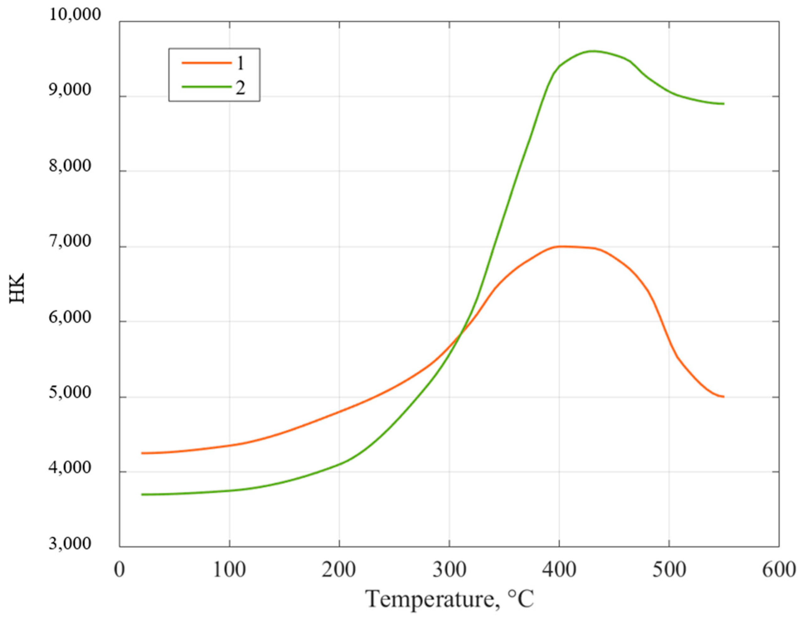
At higher temperatures and longer heating times, the microhardness decreases again—Figure 3, except for high-phosphorus coatings, whose hardness can increase at 600 °C [22].
In addition to the use of ENP coatings, chrome coatings are widely used [23,24].
Chrome coatings are resistant to the action of hydrogen sulfide, many acids and alkalis, and humid atmospheres. Based on their functional purpose, different types of precipitates and their combinations are used: matte and shiny. Gray coatings have hardness (917–1224 HV), but low plasticity and wear resistance. Shiny chrome coatings also have high hardness (765–1122 HV) but crack under internal stresses at thicknesses greater than 1 µm. Matte chromium coatings have a hardness of about 459–611 HV and have increased ductility and wear resistance [25].
To increase the durability of parts subjected to mechanical wear under simultaneous exposure to an aggressive environment, matte chrome deposits are used, which better protect the base metal from corrosion than shiny ones [26].
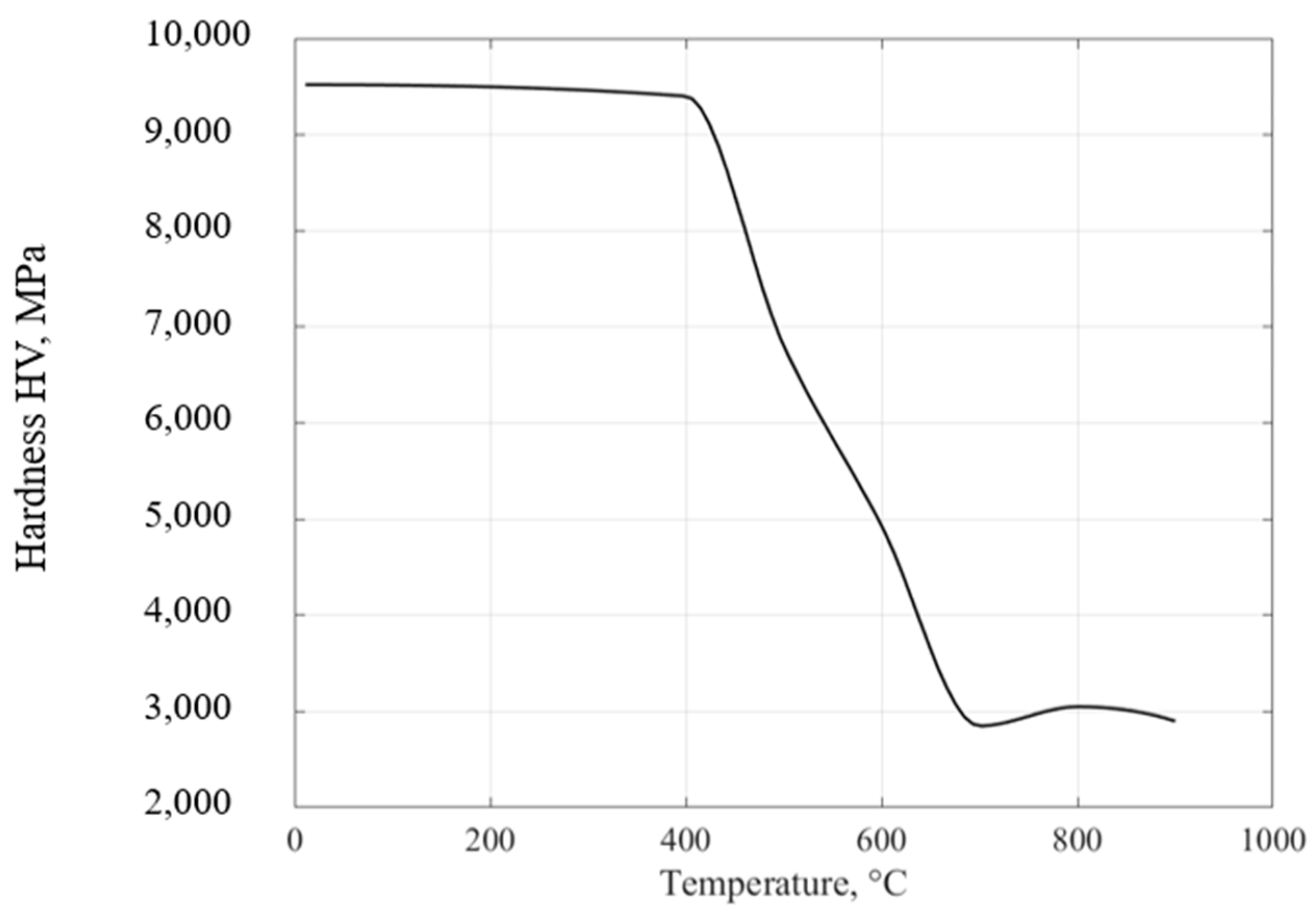
It is known that the operating temperature of traditional chromium coatings obtained from standard chromium electrolytes (GOST 9.305-84) does not exceed 450 °C. As can be seen from the data in Figure 4, the hardness of the chromium coating remains unchanged up to 400 °C, and the character of the crystal structure also does not change [27,28].
After heating the coating to 500 °C, partial recrystallization occurs, and at 700 °C and more, complete recrystallization of the chromium coating with the formation of separate layers of chromium-iron alloy and a layer of nitrides (nitrogen from air and steel) [29]. The hardness of chromium as a result of recrystallization decreases more than five times [30].
Accordingly, in order to develop new techniques for determining the thickness and hardness of ENP and chrome coatings, it is necessary to perform studies on full-scale samples.

2. Materials and Methods

2.1. Samples

To investigate the properties of nickel–phosphorus coatings, ENP-coated ball plugs used in gas pipelines were selected from several batches. The characteristics specified in the accompanying manufacturer’s documentation are shown in Table 1.
During the tests (measurements and calibration), the samples were sawn into 2 or 4 equal parts. The image of one of the samples is shown in Figure 5.
Two sets of chromium coating thickness samples (hard and matte) were fabricated. The coatings were applied by galvanic deposition, the thickness range of which was from 5 to 110 μm (Figure 6a).
The following blanks of steel grade C20E2C were used as the base metal (Figure 6b). The manufacturer’s characteristics of the chrome coating samples are summarized in Table 2.

2.2. Standard Methods for Testing of Coatings

During the incoming inspection, the thickness and hardness of coatings of ball valves should be controlled by non-destructive methods to maintain the integrity of the object of control, so, for further research, measuring instruments were selected that provide non-destructive control. The values obtained by destructive methods were chosen as reference values, the measurement result of which is less influenced by interfering parameters.
Due to the peculiarities of inspection objects, the task of selecting a hardware complex for conducting thickness and hardness measurements of coatings is multi-parametric.
At the moment, it is possible to carry out entry inspection only in specially equipped laboratories for specific types of substrates and coatings, using random sampling. For operational control of coating parameters at the production site, there are no measuring instruments that allow adjustment to the influencing parameters on the measurement result. In order to settle the control problem in factory conditions, it is necessary to solve the following problems:
(1) For ENP coatings—adjust for electromagnetic parameters influencing the coating thickness measurement result by magnetizing the coating in the range of 0.6 to 1.2 Tesla;
(2) For chrome coatings—identify the type of chrome coating of known thickness by portable eddy current thickness probes.

2.2.1. Thickness Control of Coatings

During the research, the measurement of coating thickness was performed by non-destructive and destructive methods. The group of non-destructive methods includes those that can be applied without disturbing the coating integrity. Such methods are magnetic induction [31,32], eddy current [31,32,33], and radiation [34,35]. The group of destructive methods includes the ball abrasion method [36].
The magnetic induction method of coating thickness measurement is based on the change in mutual induction between excitation (primary) and receiving (secondary) windings of the primary measuring transducer, depending on the thickness of the non-magnetic coating on a ferromagnetic base (or thickness of the ferromagnetic coating on a non-ferromagnetic base) [31,33,37].
The main problem in applying the magnetic induction method when measuring the thickness of ENP coating is that, after heat treatment, it acquires ferromagnetic properties, the magnetic characteristics of which may differ over the coating surface at different points, which leads to an unacceptable distortion of readings. Chromium coatings are non-ferromagnetic; in connection with this, the measurement of the thickness of this type of coating by the magnetic induction method does not cause difficulties.
Eddy current methods of coating thickness measurement are based on the analysis of the interaction between the electromagnetic field of the eddy current transducer and the electromagnetic field of eddy currents induced in the controlled object and depends on the electrophysical and geometric parameters of the base metal and coating [31,32]. The eddy current phase method allows measurement of the thickness of ferro- and non-ferromagnetic electrically conductive coatings on ferrous metal ball plugs according to the calibration characteristics for the given coating/base combinations, which are preliminarily taken and recorded in the transducer memory [32,38].
The coating thickness measurement results obtained by the eddy current method are directly affected by changes in the electrical conductivity and magnetic permeability of the coating [39,40,41], while such changes play almost no role in the magnetic induction method. Accordingly, using this method on ENP coatings for measurement, it is possible to measure the coating thickness more accurately than the magnetic induction method.
The measurement results of devices based on the magnetic induction and eddy current methods depend on several groups of parameters: electrophysical (specific electrical conductivity of the coating materials, σc, and the base, σb, as well as the complex relative magnetic permeability of the base material, µ ¯ b), and geometry (coating thickness, roughness, radius of curvature of the surface, etc.) [31,32,33].
When developing the measurement methodology for obtaining the reference value of coating thickness, the crater grinding method was chosen as the reference. The measurement is based on determining the geometric dimensions of a sphere (“spherical microsurface”) formed by abrasion of the coating by a steel rotating ball when an abrasive slurry is added to the contact zone. The measurement results obtained by this method do not depend on the properties of the coating. Its disadvantage is the violation of the integrity of the coating of the object of control and the impossibility of further operating the locking element.

2.2.2. Control of Mechanical Parameters (Hardness)

Classical methods of determining the basic mechanical parameters of solids based on the experimental stress–strain relationship are not applicable for coatings and hardened near-surface layers, because they require the manufacture of special test specimens. To analyze the local mechanical properties of the surface of materials and products, static methods of hardness measurement (Brinell, Vickers, and Rockwell) are traditionally used, which, due to their peculiarities, are not applicable for measuring the properties of coatings and near-surface layers in hard-to-reach places on the surface of large-sized parts and parts of complex geometry. These limitations have led to the appearance of various portable hardness testers [42]. However, the measurement result of the most common portable hardness testers (ultrasonic and Leeb hardness testers) depends on the ratio of plastic and elastic properties (yield strength and Young’s modulus), which does not allow directly relating them to the values of static hardness scales, in particular the Vickers scale. To obtain reliable results with portable hardness testers, it is necessary to calibrate them on measures whose elastic properties are close to those of the controlled objects.
In the world of scientific practice for measuring the mechanical properties of thin coatings of high hardness, the instrumented indentation method is used [43]. Due to the fact that it is not possible to use this method for the control of finished products, the following hardness measurement methods were applied: the Vickers microhardness [44] and ultrasonic contact impedance (UCI) [45] methods. The UCI method is based on the change in the resonance frequency of an elastic element (rod) as a result of indentation by a Vickers diamond pyramid into the surface of the test piece when a load is applied [46].
It is also necessary to take into account the condition that the indentation depth should not exceed 10% of the thickness of the measured coating, that is, measurements should be carried out at thicknesses more than 30 µm.

2.3. Equipment

Due to the fact that the samples have different physical properties, such as saturation magnetization, magnetic permeability, residual magnetization, hysteresis loop rectangularity, and coercive force, the choice of equipment for obtaining information was made taking these factors into account.
To achieve the multi-parametric approach to the control of the ball gate valve closure parameters, an analysis was made that allowed the determination of the necessary equipment for further research. Information on the equipment used is presented in Table 3. The measuring instruments have the following established metrological characteristics.

3. Results

3.1. ENP Coatings

3.1.1. Measurement of Coating Thicknesses

To carry out coating thickness measurements by the ball abrasion method, a set of equipment was used: a ball abrasion machine (CAT2c) for obtaining the wear crater, and a Walter UHL VMM 150 Measuring Microscope [36]. The formation of the wear crater and further measurements were carried out using a steel ball with a diameter of 20 mm. The results of the measurements are presented in Table 4.
The non-destructive measurements of coating thickness were performed by two probes realizing magnetic induction (F1) and eddy current phase (PH1) measurement methods.
Since the eddy current probe was calibrated on the coating of the control sample, its measured thickness values correspond to those obtained by the ball abrasion method. At the same time, the results of measuring the coating thickness of another sample by the PH1 transducer, according to the calibration characteristic “ENP” obtained on the control sample, differ from the results obtained by the destructive method. This is caused by a significant difference in the electromagnetic properties of the coatings.
The results of the measurements are shown in Table 4.

3.1.2. Hardness Testing

Because the thickness of the controlled chemically deposited nickel coating does not exceed 100 µm, Vickers microhardness testers are used to measure the hardness values. In this work, the HMV-G30S microhardness tester was used. Due to the design limitations of the HMV-G30S, the dimensions of the specimen for measuring coating hardness are very limited.
Loads of 0.1 kgf and 0.5 kgf were used for testing the specimen. The results of the measurements performed (average values from at least 5 measurements) are shown in Table 5.
Measurements of coating hardness were carried out by the UCI Hardness Tester KT- C with a U-10N probe. To solve the task, a probe with a load of 1 kg was used, leaving an imprint of small size and depth, which allows the measurement of relatively thin coatings. This load value is the minimum for this class of instrument while being significantly higher than loads typical of microhardness measurements using the HMV-G30S. Microhardness values obtained at a load of 500 g were used for comparison.
The results of the measurements are presented in Table 5.

3.2. Chrome Coatings

3.2.1. Measurement of Coating Thicknesses

To carry out measurements of chrome coating thicknesses, a similar equipment complex was used: a CAT2c ball abrasion machine, Walter UHL VMM 150 Measuring Microscope, and a K6-C multifunctional coating thickness measuring device with F1 and PH1 probes.
Due to the different electrical conductivity of different types of chromium, it is hard to measure coating thickness by the eddy current phase method, so the probe was used to obtain a value proportional to the coating thickness. The code characterizes the phase shift during the measurement.
The results of the measurements are presented in Table 6.

3.2.2. Hardness Testing

The loads used for the tests were 0.05 kgf, 0.1 kgf, and 0.2 kgf. Due to the fact that hardness studies should be carried out on samples with coating thicknesses of more than 30 µm, seven samples out of twelve were tested. The results of the measurements (average values of at least five measurements) are shown in Table 7.

4. Discussion

4.1. ENP Coatings

The results of the coating thickness measurements (Table 4) by the magnetic induction transducer on sample No. 1 (AD-136 2”) do not correspond to the actual coating thickness obtained by the crater grinding method. This indicates that the coating has ferromagnetic properties acquired during heat processing, which affects the readings of the magnetic induction coating thickness gauge. The presence of heat treatment is also confirmed by the high hardness of the coating.
The results of the coating thickness measurement by the magnetic induction probe on sample No. 2 (AD-136 4”) correspond to the results of the coating thickness measurement by the crater grinding method. This indicates the absence of ferromagnetic properties of the coating, which, in turn, indicates the absence of thermal treatment of the coating. This is also evidenced by the low hardness of the coating (Table 5) [22]. It should be taken into account that the change in electromagnetic parameters of the coating (specific conductivity and relative magnetic permeability) is a natural consequence of non-compliance with the parameters of the technological process of coating application. At the same time, even fluctuations of these parameters, satisfying the technological tolerances, lead to a significant change in the electromagnetic parameters of the coating, which does not allow the use of the eddy current phase method to measure the coating thickness. The magnetic induction method of thickness measurement is not sensitive to the specific electrical conductivity of the coating, and to reduce the relative magnetic permeability of the coating material, it is possible to use the technique of magnetizing the coating to saturation by an external constant magnetic field.
When measuring hardness by the ultrasonic contact impedance method, the critical parameter affecting the readings of the device is the modulus of elasticity of the material of the controlled sample [46]. Reliable values of hardness at a given calibration method with UCI can be obtained on samples with the same modulus of elasticity. The results of measuring the hardness of the coating of sample No. 1 using the UCI method (Table 5) are comparable to the results of hardness measurement by Micro Vickers with a load of 500 gf. On this basis, it can be assumed that the modulus of elasticity of the hard coating is close to the modulus of elasticity of unalloyed steel, for which the instrument was calibrated. The results of measuring the hardness of coating sample No. 2 by means of the UCI impedance method are radically different from the results of measuring the hardness by Micro Vickers (780 and 550 HV, respectively). This indicates that the modulus of elasticity of the coating without heat treatment is significantly lower than that of the annealed heat-strengthened coating.

4.2. Chrome Coatings

The results of the chrome hard and matte coatings thickness measurements (Table 6) by magnetic induction probe correspond to the actual coating thickness obtained by the crater grinding method.
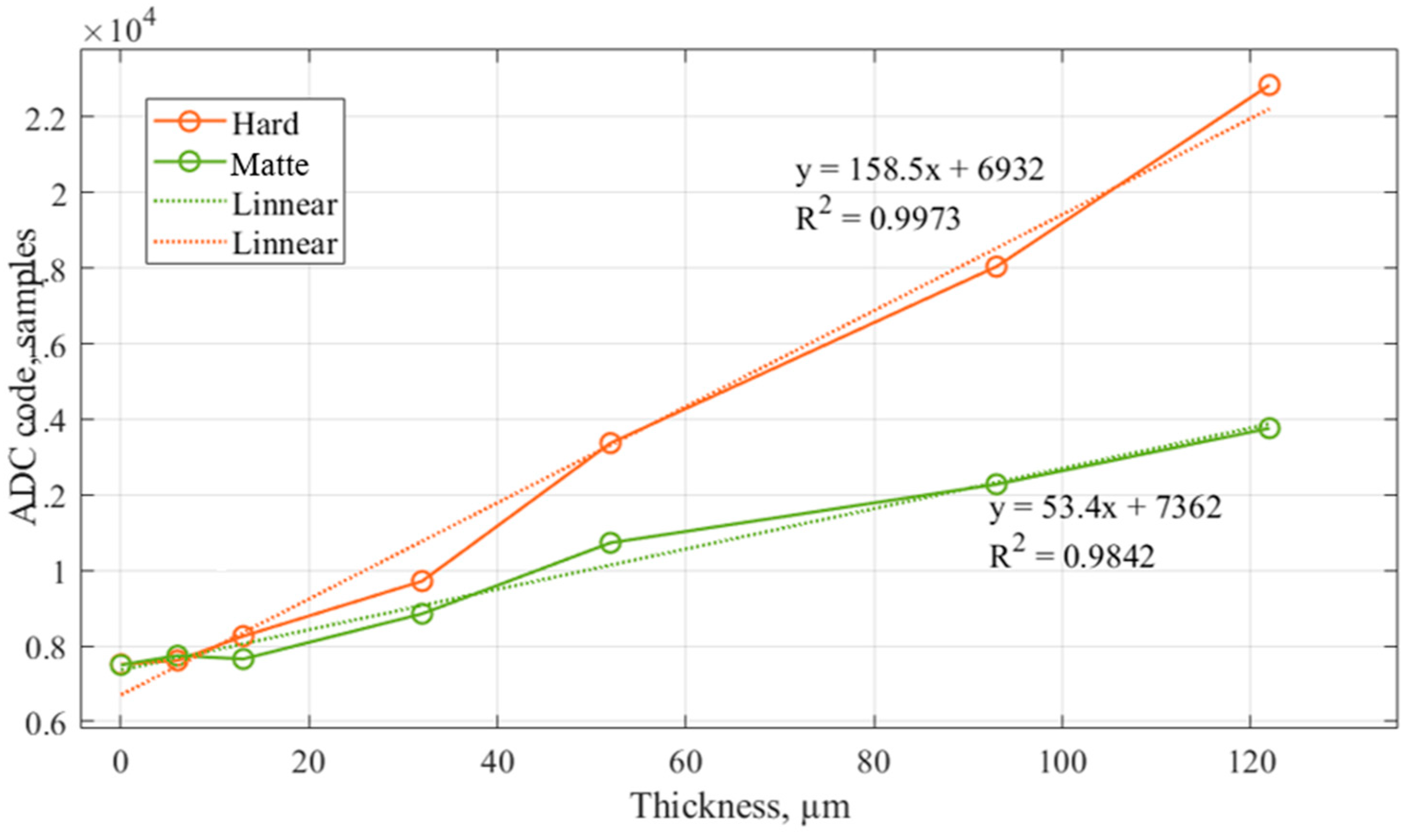
According to the study of the dependence of the ADC code of the eddy current phase probe PH1 on the coating thickness of two types of chromium (Figure 7), it can be seen that the above-mentioned types of chromium coatings have different electrical conductivity because electrical conductivity depends on the mode selected in the coating process.
The hardness studies confirm the stated characteristics of this parameter in the obtained samples of coatings in laboratory conditions (Table 7). The hardness values of the chromium coating are in the range from 632 to 1028 HV, thus, a large variation in the measurement is caused by the high grain size of the obtained surface; when carrying out the procedure of grinding the sample, the grain size does not decrease. The values of the matte chrome hardness are in the range of 371 to 382 HV.
During the measurements of the thickness of electrodeposited chrome coatings, the results obtained with the magnetic induction transducer were confirmed by the crater grinding method, which indicates the absence of ferromagnetic properties of the coating. When conducting a study of the thickness of coatings by eddy current phase probe, ADC code values were obtained, which allowed us to compare the electrical conductivity of the two types of chromium coatings. In graphical form, the plotted characteristics of the ADC code from the coating thicknesses of hard and matte chromium have a different slope of the angle, which is the basis for the assumption that the coatings differ in electrical conductivity.
By conducting hardness tests, the characteristics of matte chrome and hard chrome coatings were confirmed. The hardness of matte chromium does not exceed 382 HV, and hard chromium, 1028 HV.
Depending on the mode of application of electrodeposited chromium coatings (hard, matte, shiny), the electrical conductivity differs. Knowing the thickness obtained by conducting measurements by the magnetic induction method, it can be assumed that the change in the phase shift angle of the eddy current probe allows us to identify the type of chromium coating under study. Proceeding from the above, it is possible to identify the type of chrome coating with the help of an eddy current thickness gauge, which is mass-produced. Significant advantages of this method of control are the possibility to assess hardness directly in the field, without resorting to the laboratories of the technical control department, and the preservation of the integrity of the object of control with the possibility of its further use.

5. Conclusions

Having analyzed the literature and the state of modern methods of control of metal coatings of ball plugs by such parameters as thickness and hardness, it was confirmed that there is no possibility of control of parameters by the same measuring instruments for different coatings. For the complex control of coatings, it is necessary to take into account such parameters as electrophysical—σc, σb, µ ¯ b—and geometrical coating thickness, d, roughness, Ra, and radius of surface curvature, R. The possibility of using the crater grinding method as a reference method for coating thickness measurement was confirmed since the measurement result is not affected by the above parameters. Portable thickness gauges should be used after preliminary calibration on a sample, which is identical in properties to the objects of control, due to the fact that in case of violations of the technological process, it is possible to change electromagnetic properties. For hardness control, it is suggested to use selective control of ball plugs on measuring instruments realizing the method of hardness measurement, HV. Also, the possibility of using eddy current thickness gauges, realizing the phase method of measurement, for carrying out operational control of the hardness of chrome coatings taking into account the known thickness is confirmed.
  • The performed studies confirmed the necessity of operational and output complex multi-parameter control of metal coatings of shut-off valve ball plugs by unified methods to ensure the uniformity and required accuracy of measurements.
  • The thickness measurement of ENP coatings should be performed by the magnetic induction method before the heat treatment operation.
  • Taking into account the range of standardized coating thicknesses, hardness testing (hardness measurement) may be performed by the UCI method with a load not exceeding 10 N.
  • For adjustment and calibration of the equipment before measurement, it is necessary to use ball plugs certified by direct measurement methods, with coatings manufactured in accordance with the technologies and materials used at the enterprises.
  • During the incoming inspection, it is necessary to use similar instruments, control samples, and measurement methods. It should also be taken into account that the incoming inspection of ENP coating thickness by electromagnetic methods does not provide the required accuracy.

Author Contributions

Conceptualization, V.S.; methodology, A.U.; software, V.A.; validation, V.A.; formal analysis, V.S.; investigation, V.A.; resources, V.S.; data curation, V.A.; writing—original draft preparation, V.A.; writing—review and editing, V.S.; visualization, V.A.; supervision, V.S.; project administration, A.U. All authors have read and agreed to the published version of the manuscript.

Funding

This research received no external funding.

Data Availability Statement

Dataset available on request from the authors.

Acknowledgments

The authors express their deep gratitude to Kirill V. Gogolinskii, Pavel V. Solomenchuk, and Evgeny S. Gorlanov for their practical and moral support in achieving the objectives of this scientific work. The investigation was conducted in the LLC “CONSTANTA” and Scientific Center “Issues of Mineral and Technogenic Resources Processing”.

Conflicts of Interest

The authors declare no conflicts of interest.

References

  1. Gogolinskii, K.V.; Alekhnovich, V.V.; Ivkin, A.E.; Umanskii, A.S.; Solomenchuk, P.V. Study of methods of incoming inspection of metal coatings of shut-off valves of pipelines. Kontrol’. Diagn. 2023, 4, 38–47. [Google Scholar] [CrossRef]
  2. Lyubchik, A.N.; Krapivskii, E.I.; Bolshunova, O.M. Prediction of the Technical Status of Pipeline Based on Analysis. J. Min. Inst. 2011, 192, 153–156. [Google Scholar]
  3. Shammazov, I.; Dzhemilev, E.; Sidorkin, D. Improving the Method of Replacing the Defective Sections of Main Oil and Gas Pipelines Using Laser Scanning Data. Appl. Sci. 2022, 13, 48. [Google Scholar] [CrossRef]
  4. Yamilev, M.Z.; Pshenin, V.V.; Matveev, D.S.; Podlesniy, D.S.; Bezimyannikov, T.I. The Use of Compact Inspection Devices for Monitoring the Technical Condition of Pipelines in Protective Cases. Neft. Khozyaystvo Oil Ind. 2022, 2, 106–110. [Google Scholar] [CrossRef]
  5. Krizsky, V.N.; Kosarev, O.V.; Alexandrov, P.N.; Luntovskaya, Y.A. Mathematical Modeling of the Electric Field of an In-Line Diagnostic Probe of a Cathode-Polarized Pipeline. J. Min. Inst. 2024, 265, 156–164. [Google Scholar]
  6. Dzhemilev, E.R.; Shammazov, I.A.; Sidorkin, D.I.; Mastobaev, B.N.; Gumerov, A.K. Developing Technology and Device for the Main Pipelines Repair with Cutting out Their Defective Sections. Neft. khozyaystvo Oil Ind. 2022, 10, 78–82. [Google Scholar] [CrossRef]
  7. Vasin, S.A.; Plakhotnikova, E.V. Electric Drive Setting Torque Calculation Method in Electric Drive Shut-off Valve System with Rectilinea Displacement of the Valve Closure. J. Min. Inst. 2018, 232, 407–412. [Google Scholar] [CrossRef]
  8. Dong, V.H. Ball Valves for Gas Pipelines. In Proceedings of the New Technologies for the Oil and Gas Region: Materials of the All-Russian Scientific and Practical Conference of Students, Graduate Students and Young Scientists, Dedicated to the 50th Anniversary of TII-TyumGNGU, Tyumen, Russia, 1 January 2013; pp. 357–359. [Google Scholar]
  9. Gorlanov, E.S.; Leontev, L.I. Directions in the Technological Development of Aluminium Pots. J. Min. Inst. 2024, 266, 246–259. [Google Scholar]
  10. Piksaykin, R.V.; Stepanenko, O.A. Control of Gas and Liquid Leakage in Ball Valves of Main Pipelines. Weld. Diagn. 2012, 3, 51–52. [Google Scholar]
  11. Kovalskaya, K.V.; Gorlanov, E.S. Al–Ti–B Master Alloys: Structure Formation in Modified Alloys. Tsvetnye Met. 2022, 7, 57–64. [Google Scholar] [CrossRef]
  12. API 6D:2008; Specification for Pipeline Valves. American Petroleum Institute: Washinton, DC, USA, 2008.
  13. ISO 14313:2007; Petroleum and Natural Gas Industries. Pipeline Transportation Systems. Pipeline Valves. International Standard Organization: Geneva, Switzerland, 2007.
  14. ASME B16.34-2013; Valves—Flanged, Threaded, and Welding End. The American Society of Mechanical Engineers: New York, NY, USA, 2013.
  15. MSS SP-55; Quality Standard for Steel Casting for Valves, Flanges, Fittings and Other Piping Components. Manufacturers Standardization Society: Alexandria, VA, USA, 2001.
  16. MU.10.36; Irkutsk Oil Company OOO “Unified Technical Requirements for the Supply of Ball Valves”. Irkutsk Oil Company: Irkutsk, Russia, 2019.
  17. STO Gazprom 2-4.1-1108-2017; Pipeline Fittings. Special Ball Valves. General Technical Conditions. PJSC Gazprom: Moscow, Russia, 2017.
  18. Singh, D.D.N.; Ghosh, R. Electroless Nickel–Phosphorus Coatings to Protect Steel Reinforcement Bars from Chloride Induced Corrosion. Surf. Coat. Technol. 2006, 201, 90–101. [Google Scholar] [CrossRef]
  19. Elsener, B.; Crobu, M.; Scorciapino, M.A.; Rossi, A. Electroless Deposited Ni–P Alloys: Corrosion Resistance Mechanism. J. Appl. Electrochem. 2008, 38, 1053–1060. [Google Scholar] [CrossRef]
  20. ACUÑA, J.C.; Echeverría, F.E. A review with respect to electroless ni-p (enp) coatings: Fundamentals and properties. Part I. J. Basic Appl. Res. Int. 2015, 10, 79–85. [Google Scholar]
  21. Popov, G.; Bolobov, V.; Zhuikov, I.; Zlotin, V. Development of the Kinetic Equation of the Groove Corrosion Process for Predicting the Residual Life of Oil-Field Pipelines. Energies 2023, 16, 7067. [Google Scholar] [CrossRef]
  22. Hamburg, Y.D. Chemical Nickel Plating (Production of Nickel-Phosphorus Coatings by Electrocatalytic Reduction with Hypophosphite); RAS: Moscow, Russai, 2020. [Google Scholar]
  23. Martinuzzi, S.M.; Donati, L.; Giurlani, W.; Pizzetti, F.; Galvanetto, E.; Calisi, N.; Innocenti, M.; Caporali, S. A Comparative Research on Corrosion Behavior of Electroplated and Magnetron Sputtered Chromium Coatings. Coatings 2022, 12, 257. [Google Scholar] [CrossRef]
  24. Wang, L.; Liao, Q.; Gan, S. Corrosion Behavior of Chromium Coating on Ferritic/Martensitic Steels in High Temperature Lbe. SSRN 2022, 7, 1–23. [Google Scholar] [CrossRef]
  25. Kovensky, I.M. Metal Coatings of Parts and Structures of Oil and Gas Equipment. In Heat Treatment: Textbook; TyumGNGU: Tyumen, Russia, 2014; ISBN 978-5-9961-0829-9. [Google Scholar]
  26. Khozyaev, I.A. Fundamentals of Food Engineering Technologies: Textbook; Lan: St. Petersburg, Russia, 2022; ISBN 978-5-8114-3597-5. [Google Scholar]
  27. Solodkova, L.N.; Kudryavtsev, V.N. Electrolytic Chrome Plating; Globus: Moscow, Russia, 2007. [Google Scholar]
  28. Salakhova, R.K.; Tikhoobrazov, A.B. Thermal resistance of electrolytic chromium coatings. Aviat. Mater. Technol. 2019, 55, 60–67. [Google Scholar] [CrossRef]
  29. Pletnev, D.V.; Brusentsova, V.N. Basics of Wear-Resistant Chrome Plating Technology; Mashgiz: Moscow, Russia, 1953. [Google Scholar]
  30. Shluger, M.A. Acceleration and Improvement of Chrome Plating of Machine Parts; Mashgiz: Moscow, Russia, 1961. [Google Scholar]
  31. Potapov, A.I.; Syasko, V.A. Non-Destructive Methods and Means of Monitoring the Thickness of Coatings and Products. In Scientific, Methodological, Reference Manual; Humanistics: St. Petersburg, Russia, 2009; p. 904. [Google Scholar]
  32. Kostin, V.N.; Smorodinsky, Y.G. Multi-Purpose Hardware-Software Systems for Active Electromagnetic Control as a Trend. Defectoscopy 2017, 7, 23–34. [Google Scholar]
  33. Gromyka, D.S.; Gogolinskiy, K.V. Introduction of Evaluation Procedure of Excavator Bucket Teeth into Maintenance and Repair: Promptse. MIAB. Min. Inf. Anal. Bull. 2023, 8, 94–111. [Google Scholar] [CrossRef]
  34. Salmi, M.; Magrini, A.; Gigante, G.E.; Barra, O.A. Coating Thickness Measurement by Means of the Radioisotope X-ray Fluorescence Technique. Isot. Isot. Environ. Health Stud. 1978, 14, 380–381. [Google Scholar] [CrossRef]
  35. Mashin, N.I.; Leontyeva, A.A.; Tumanova, A.N.; Ershov, A.A. X-ray Fluorescence Method for Determining the Thickness of Aluminum Coating on Steel. J. Appl. Spectrosc. 2011, 78, 454–459. [Google Scholar] [CrossRef]
  36. Gogolinsky, K.V.; Ivkin, A.E.; Alekhnovich, V.V.; Vasiliev, A.Y.; Tyurnina, A.E.; Vasiliev, A.S. Evaluation of the Accuracy Indicators in Determination of the Coating Thickness by Crater Grinding Method. Ind. Lab. Diagn. Mater. 2020, 86, 39–44. [Google Scholar] [CrossRef]
  37. Syasko, V.A.; Vasilev, A.Y. Pulse magnetic thickness inspection of metallic coatings. Defectoscopy 2021, 9, 63–70. [Google Scholar] [CrossRef]
  38. ISO 21968:2019; Non-Magnetic Metallic Coatings on Metallic and Non-Metallic Basis Materials—Measurement of Coating Thickness—Phase-Sensitive Eddy-Current Method. International Standard Organization: Geneva, Switzerland, 2019.
  39. Chernyshev, A.V.; Zagorskiy, I.E.; Sharando, V.I. Multi-Frequency Method of Control for Eddy Current Thickness Measurement. Proc. Natl. Acad. Sci. Belarus Phys. Ser. 2019, 64, 118–126. [Google Scholar] [CrossRef]
  40. Chernyshev, A.V.; Zagorskiy, I.E.; Sharando, V.I. Control the Thickness of the Chrome Coating Using Eddy Currents Method. Non-Destr. Test. Control 2021, 64, 38–42. [Google Scholar]
  41. Shakhnazarov, K.Y.; Vologzhanina, S.A.; Khuznakhmetov, R.M. A Relationship between Abnormal Electrical Properties in Non-Ferrous Alloys and Phase Equilibrium Diagrams. Tsvetnye Met. 2024, 2, 53–59. [Google Scholar] [CrossRef]
  42. Gogolinskii, K.V.; Syasko, V.A.; Umanskii, A.S.; Nikazov, A.A.; Bobkova, T.I. Mechanical Properties Measurements with Portable Hardness Testers: Advantages, Limitations, Prospects. J. Phys. Conf. Ser. 2019, 1384, 012012. [Google Scholar] [CrossRef]
  43. Useinov, A.; Gogolinsky, K. Mechanical Properties of Ultrathin Carbon Diamond-like Coatings. Nanoindustry 2010, 5, 54–57. [Google Scholar]
  44. ISO 6507-1:2023; Metallic Materials—Vickers Hardness Test. Part 1: Test Method. International Standard Organization: Geneva, Switzerland, 2023.
  45. ASTM A1038-19; Standard Test Method for Portable Hardness Testing by the Ultrasonic Contact Impedance Method. ASTM: West Conshohocken, PA, USA, 2019.
  46. Ashirova, A.D.; Gogolinsky, K.V.; Nikazov, A.A. Possibilities of Using Portable Hardness Testers for Non-Destructive Testing of the Mechanical Properties of Coatings. In Proceedings of the XXII All-Russian Conference on Non-Destructive Testing and Technical Diagnostics, Moscow, Russia, 3–5 March 2020; Publishing House “Spectrum”: Moscow, Russia, 2020; pp. 181–184. [Google Scholar]
Figure 1. Dependence of coercive force of Ni-P alloy material comprising an increasing concentration of P [22].
Inventions 09 00078 g001
Figure 2. Microhardness (Vickers) of Ni-P coatings directly after deposition (1) and after heat treatment under optimal conditions (2) depending on the phosphorus content in the coating. The arrows show the increase in microhardness with heat treatment.
Inventions 09 00078 g002
Figure 3. Measurement of hardness (by Knoop) after heat treatment at different temperatures for one hour. Phosphorus content in the coating: 1–4%, 2–9% [22].
Inventions 09 00078 g003
Figure 4. Dependence of hardness of chromium coatings on the temperature of heat treatment [25].
Inventions 09 00078 g004
Figure 5. Sample No. 1 AD-136 2” for measurements and calibration.
Inventions 09 00078 g005
Figure 6. (a) One of a set of chrome plating thicknesses (matte); (b) Drawing of the part to be electroplated with chrome plating.
Inventions 09 00078 g006
Figure 7. Dependence of the obtained ADC code on the thickness of chrome coatings.
Inventions 09 00078 g007
Table 1. ENP samples and their characteristics.
NameDiameter, mmBase MetalCoatingCoating Thickness, μmCoating Hardness, HV
AD-136 2”84LF2 1ENP76 ± 3910
AD-136 4”170LF2ENP76 ± 3910
1 LF2 per ASTM A350.
Table 2. Chrome samples and their characteristics, as specified by the manufacturer.
NameType of ChromeBase MetalCoatingCoating Thickness, μmCoating Hardness, HV
5–1HardC20E2CChrome5 ± 1700
10–1HardC20E2CChrome10 ± 3700
35–1HardC20E2CChrome35 ± 4700
50–1HardC20E2CChrome50 ± 5800
90–1HardC20E2CChrome90 ± 6800
110–1HardC20E2CChrome110 ± 10900
5–2MatteC20E2CChrome5 ± 1350
10–2MatteC20E2CChrome10 ± 3350
20–2MatteC20E2CChrome20 ± 4350
40–2MatteC20E2CChrome40 ± 5370
70–2MatteC20E2CChrome70 ± 6370
110–2MatteC20E2CChrome110 ± 10380
Table 3. Measurement methods and equipment used.
No.Measured Parameter/Method of MeasurementEquipmentMetrological CharacteristicValue
1Coating thickness/Crater grinding methodCAT2c 1 ball abrasion machine, Walter UHL VMM 150 2 Measuring Microscope Accuracy parameter (error limits for p = 0.95), ±δ6.0%
2Coating thickness/
Magnetoinduction method
K6-C Multifunctional Coating Thickness Gauge with F1 3 probeLimit of acceptable basic absolute error of coating thickness measurements at ambient air temperature (20 ± 5) °C, mm±(0.01 h + 0.001)
3Coating thickness/
Eddy current phase method
K6-C Multifunctional Coating Thickness Gauge with PH1 3 probeLimit of acceptable basic absolute error of coating thickness measurements at ambient air temperature (20 ± 5) °C, mm±(0.02 h + 0.001)
4Hardness HV/ Static method
(Vickers microhardness)
Shimadzu HMV-G30S Micro Hardness Tester Limit of acceptable error of loads in the main/additional ranges, not more than±2%
5Hardness HV/
Ultrasonic contact impedance method
KT-C Hardness Tester with U-10N 4 probeLimit of acceptable absolute error of hardness measurement, units of measurement±20 HV
Table 4. ENP coating thickness measurement results (average of 5 results), μm.
NameDeclaredCrater Grinding MethodMagnetoinduction MethodEddy Current Phase Method
AD-136 2”76 ± 4153.0 ± 1.336 ± 1147 ± 3
AD-136 4”76 ± 470.0 ± 1.170 ± 245 ± 1
Table 5. ENP coating hardness measurement results (average of 5 results), HV.
NameDeclaredStatic MethodUltrasonic Contact Impedance Method
Load 0.1 kgfLoad 0.5 kgf
AD-136 2”910 ± 20908 ± 18751 ± 18740 ± 20
AD-136 4”910 ± 20441 ± 18520 ± 18780 ± 20
Table 6. Chrome coating thickness measurement results (average of 5 results).
NameCoating Thickness, μmCode Value for Thickness Measurement, Units
DeclaredCrater Grinding MethodMagnetic Induction MethodEddy Current Phase Method
5–15 ± 16.0 ± 1.16 ± 17436 ± 56
10–110 ± 312.0 ± 1.613 ± 17655 ± 63
35–135 ± 434.0 ± 3.132 ± 18852 ± 95
50–150 ± 551.0 ± 2.952 ± 210,730 ± 116
90–190 ± 695.0 ± 3.993 ± 212,278 ± 120
110–1110 ± 10118.0 ± 12.9122 ± 313,762 ± 128
5–25 ± 11.8 ± 1.32 ± 17615 ± 33
10-210 ± 38.0 ± 1.37 ± 18261 ± 23
20–220 ± 417.0 ± 2.019 ± 19717 ± 32
40–240 ± 545.0 ± 4.145 ± 213,369 ± 53
70–270 ± 675.2 ± 3.080 ± 418,039 ± 248
110–2110 ± 10101.1 ± 6.1111 ± 322,846 ± 406
Table 7. Chrome coating hardness measurement results (average of 5 results).
NameCoating Thickness, Crater Grinding Method, μmStatic Method, HVUltrasonic Contact Impedance Method
Hardness, HVLoad, kgf
35–134.0 ± 3.1632 ± 167 0.05717 ± 4
50–151.0 ± 2.91028 ± 1920.1779 ± 10
90–195.0 ± 3.9821 ± 1190.2844 ± 9
110–1118.0 ± 12.9972 ± 990.2754 ± 8
40–245.0 ± 4.1377 ± 350.1358 ± 10
70–275.2 ± 3.0371 ± 290.2363 ± 9
110–2101.1 ± 6.1382 ± 110.2318 ± 5
Disclaimer/Publisher’s Note: The statements, opinions and data contained in all publications are solely those of the individual author(s) and contributor(s) and not of MDPI and/or the editor(s). MDPI and/or the editor(s) disclaim responsibility for any injury to people or property resulting from any ideas, methods, instructions or products referred to in the content.