Abstract
With the rise in construction costs and aging of existing concrete structures, retrofitting and strengthening have gained more popularity. Among all of the available techniques, adding new repairing layers on top of old concrete ones has proven to be highly effective. However, the efficacy of such method is dependent on the performance of the cold bond between old and new layers of concrete whose establishment requires different considerations, such as paying attention to the properties of concrete layers, namely their strength, permeability, aggregate size, density, etc., and the qualities of the interface between the layer, such as how wet it is or its roughness degree. In this paper, the factors which can impact shear and tensile bond strength are fully discussed while being categorized into two major groups of factors related to each concrete layer’s properties and those directly associated with the connection area. The durability of the bond after exposure to various environments in terms of temperature and relative humidity is also addressed and then a list and comparison of numerous tests that are commonly conducted to measure the bond strength are provided. The findings indicate the characterization of suitable materials and surface roughening techniques which can ensure an adequate bonding between substrate and overlay, along with recommendations for the scope of future research.
1. Introduction
The Federal Highway Administration (FHWA) has reported that 36% of bridges in the USA require repair [1], and rehabilitation of old structures which have reached the end of their service life, in order to be more economical than reconstruction, might lead to casting concrete layers at different times on top of each other [2]. As an illustration, in many cases, the cross-section of concrete members can be fully or partially covered by a new layer of concrete, which is called concrete jacketing [3]. Jacketing can have both structural and non-structural purposes, such as restoring the load-bearing capacity of elements by increasing cross-sectional area and confinement [4], enhancing concrete appearance, protection of reinforcing bars from abrasive substances and decreasing the level of permeability [5]. When concrete jacketing is performed, a bond is formed between the old and new layers of concrete and, clearly, the efficiency of employing rehabilitation techniques is highly dependent on how resistant such a bond is. The main mechanisms associated with the integrity of such an interface are Van Der Waals forces and mechanical interlock. Figure 1 shows the components of the system and how it works [5,6]. Van Der Waals forces have proven to be mostly limited to the hydration of cement particles located in the surface of old concrete, which were not hydrated in the first place, so the chemical bond formed between old and newly-placed concrete is weak [7]. On the other hand, a strong mechanical interlock is directly associated with three main conditions:
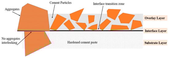
Figure 1.
Details of substrate–overlay bond and interfacial transition zone [6].
- Substrate concrete must be strong enough, without any major cracks or unsoundness;
- Moisture content and temperature of the substrate has to be suitable;
- Substrate surface must be clean of any dust or dirt [8].
However, notwithstanding such considerations, in most cases, the region between substrate and overlay acts extremely weakly due to the formation of interfacial shear stresses and lack of sufficient adhesion between the layers, and the severity of this phenomenon might even lead to the adhesive failure of the entire system. Adhesive failure denotes debonding in the interface before concrete crushing or spalling occurs [3].
This mode of failure happens in structures where inadequacy of their bond strength leads to premature fracture rather than using the mechanical capacity of concrete layers to the full [9], so the cold joint between concrete repair layer and the substrate should be able to resist any kind of stress induced by either static or cyclic load, temperature change, shrinkage, etc. [10], or degradation of the system will lead to cracking, which results in corrosion of steel rebars and leakage, or even brittle failure [11].
Furthermore, due to the ever-increasing popularity of prefabrication in building new structures, especially bridges, grouting the connection region between the prefabricated elements is essential. This practice will also form a bond between layers of old and new concrete, which has a direct impact on the overall performance and stability of the structure and, if a bond which is strong enough is not achieved, concrete layers might be separated from each other and sometimes even lead to structural collapse. Such possibilities plus the considerable costs of repair have led to the necessity of proper bonding of concrete to ensure both safety and a monolithic performance of the concrete elements. Many studies so far have experimentally and numerically investigated the relevant factors influencing bond performance, the applicable techniques for improving it and quantifying its strength. Whereas the research began in the 1960s and is still ongoing, a conclusive summary of all the parameters involved in concrete-to-concrete bonding is not available. This paper aims at reviewing any kind of factor which can directly and indirectly influence bond strength, the experimental tests available for assessing this, and suggesting some insights for future investigation. The main objectives of this paper are providing the parameters involved in bond performance into separate categories with their comparison, some of the previous research results, and the explanation behind the effectiveness of the factors, while listing the primary tests for evaluating the shear strength at the interface of layers, their differences, and considerations that must be taken into account for selecting the proper one.
2. Influential Factors on Bond Performance
The shear strength of the interface between old and new concrete layers is influenced by the simultaneous effect of three actions: cohesion, friction and dowel action. Cohesion refers to the adhesion of concrete layers and their mechanical interlock; friction is related to slippage of layers on each other, which depends on concrete surface and induced normal stresses; and dowel action represents the deformation of any reinforcement passing the interface [12]. Hence, many factors are involved in shear resistance of a bond and a deep understanding of these seems necessary, since bond performance varies to a great extent with the characteristics of concrete layers and the methods employed for surface preparation. These parameters are categorized into the qualities which are associated with the interface between the layers, such as relative humidity of the interface, presence of bonding agents and surface roughness, and those related to characteristics of each layer individually, such as strength, workability, age and thickness. Some of these factors will be elaborated on in the following sections.
2.1. Influential Features of Concrete Layers
Different features of both substrate and overlay concrete and their mechanical properties can change the bond strength and play a vital role in the failure mode of the system, such as compressive strength, age, type of aggregate and binder, level of shrinkage, etc., [3] which will be discussed in the following part.
2.1.1. Compressive Strength
It is impossible to neglect the impact of added concrete mechanical properties on bond behavior and one of these characteristics is compressive strength [13]. Different studies have shown that an increment in the compressive strength of added concrete will raise the bond strength and that is why high performance and ultra-high performance concrete are favorable and more advantageous for repairing purposes [14,15,16,17,18]. A higher compressive strength is equated with a denser matrix, fewer gaps at the interface, and thereby a better Interfacial Transition Zone (ITZ) quality, which can ultimately lead to a cohesive and stronger bond [19,20]. Some studies have even shown a doubly higher shear resistance in the case of using UHPC compared to normal concrete (NC) [3,21].
High-strength concrete (HSC) and ultra-high-performance concrete (UHPC) are chosen as suitable options for retrofitting purposes because their application can minimize material usage since only a thin layer can strengthen the structure and protect it from chloride attack and water penetration [15]. Moreover, the comparison of utilizing HSC and NC for strengthening reinforced concrete members has illustrated the beneficial influence of HSC rather than NC on bond strength in many studies [19]. This agrees with the observations of Iavarone et al. (2023), who made samples with different substrate and overlay and concluded that HSC is the best option for retrofitting structures with low-strength elements. An increase in the shear stress at the interface was also witnessed with the growth of substrate strength, especially when no roughening technique was employed [22]. This was in line with the results obtained by Zhang et al. (2020), who chose three compressive strengths of 30 MPa, 40 MPa and 50 MPa for concrete substrates and explained that the shear strength of NC–UHPC composites increases linearly with their compressive strength [23]. Beushausen et al. (2008) experimentally discovered that the shear resistance of concrete composite specimens is almost 10% of the compressive strength of the new layer of concrete, regardless of its age. In addition, the higher the compressive strength became, the lower this ratio was [24]. This growth in bond strength can be justified by the linear increase in shear stresses and their corresponding normal stresses at the interface for higher concrete strengths. Such a rise in shear stresses results in a higher interfacial friction that is beneficial to bond behavior [14].
While the majority of the experimental investigations are in favor of a higher compressive strength for ensuring bond integrity, numerical studies are also providing similar results, plus developing models for prediction of bond performance based on strength of layers. Momani et al. (2023), for instance, proposed an artificial neural network (ANN) model to estimate the bond strength between HSC and NC with good accuracy, considering the effects of compressive strength and other parameters [25].
2.1.2. Shrinkage
Suitable dimensional stability, which is referred to as low or no shrinkage, is a contributory factor to a durable concrete-to-concrete connection because separation of concrete layers from each other [11] or interlayer slip [26] can occur due to three different mechanisms:
- Formation of microcracks in the interface because of the inner tensile stresses induced by shrinkage;
- Enlargement of bigger pores to enhance the overall volume and interconnections between the pores and a higher amount of permeability;
- Drying out and partial collapsing of Calcium–Silicate–Hydrate (CSH) sheets in concrete, which cause an expansion of capillary pores, resulting in a “coarser” microstructure [27].
All of the above mentioned mechanisms happen at the same time and are mostly activated by a high rate of evaporation from the surface, which is drying shrinkage [26], and since the expansion and contraction of concrete layers is restricted, the infliction of tensile, shear and normal stresses by the loss of capillary water goes further, to the point of either delamination [28,29] or ingress of detrimental chemicals, such as sulphates or chlorides [30]. Consequently, it is of vital importance to take the shrinkage of new concrete and differential shrinkage, which denotes the difference in the amount of shrinkage of layers into account, especially because the old layer has negligible shrinkage while the new one begins to shrink soon after being set, due to hardening [5].
As shrinkage is highly influential on the bond behavior, various studies have investigated its impact and tried to mitigate it using different methods. The long-term (a period of approximately 2 years) impact of differential shrinkage on bond strength and durability was assessed in a study by Beushausen et al. (2008). A considerable reduction of 25% was experienced in specimens’ interfacial strength due to shrinkage [24]. Qin et al. (2019) incorporated Shrinkage Reducing Admixtures (SRAs) into concrete overlay mix design and exposed it to moisture attack for different durations to indicate whether decreasing shrinkage is capable of increasing the durability and compatibility of new and old concrete layers. The four-point bending test results demonstrated an approximate 10%, 15% and 23% growth of interfacial fracture toughness for 0, 2 and 4 weeks of moisture exposure, respectively, proving the positive effect of lower shrinkage on bond behavior [31]. Toledo et al. (2020) observed that regardless of the substantial early age shrinkage of UHPC overlays on bridge decks because of high cement and low coarse aggregate content [32], no significant stresses were formed at the interface to affect bond strength, and this was due to a low modulus of elasticity during the early ages [33].
2.1.3. Supplementary Cementitious Materials
The properties of materials used either in the overlay or substrate can arguably alter the characteristics of the interface and its strength. Cement-based materials are amongst the most popular due to their low cost, suitable mechanical properties and compatibility with concrete [18]. Furthermore, sustainability in the construction field has become immensely important in recent years and one of the ways to produce more sustainable and environmentally-friendly materials is by replacing Portland cement either fully or partially with supplementary cementitious materials (SCMs) that are the by-products of other industries. SCMs can decrease the amount of harmful emissions in the atmosphere and the waste produced due to different industrial activities [34].
One of the most common SCMs that can be used in concrete mix design is silica fume because of its promising impacts on concrete, such as lower porosity, higher strength and lower bleeding ratio [35]. Momayez et al. (2005) investigated the impact of the application of different amounts (0%, 5%, 7% and 10%) of silica fume in concrete overlays on bond strength and worked out that regardless of the type of bond test performed, there is a growth in bond strength as the amount of silica fume increases. However, when the content of silica fume is over 7%, its impact becomes trivial [36]. This increase is probably due to changing the microstructure at the interface and the micro-filler effect of silica fume [37]. Silica fume also has a positive impact on the compressive strength of concrete to the extent that an addition of merely 15% silica fume can improve the 28-day compressive strength of concrete by more than 20% [35] and a higher strength equals a better bond performance, as mentioned earlier.
Another prevalent SCM that is employed in retrofitting purposes is fly ash, which is the by-product of energy plants burning coal [38]. The chemical composition of different types of fly ash is highly varied because it depends on the kind of fuel and the utilized technique for its collection, and such different characteristics as particle size and number of amorphous components can also lead to different behavior [39]. For example, the amount of SiO2, Al2O3 and CaO which exist in different kinds of fly ash will lead to different bond strengths. When the content of CaO is high in the employed fly ash, the performance of the bond between old and new concrete is ameliorated, yet its long-term impact and the effect of other chemical compositions concentrated in fly ash has not been investigated so far [37]. In a study, different amounts of fly ash were added to a concrete mixture and the short-term strength of the bond was decreased considerably, while an improvement was witnessed in the long run due to the positive impact of fly ash on the microstructure of the interface [40].
Geopolymer binders, which are also an environmentally-friendly substitute for Portland cement and can be adopted in sustainable construction, have been widely studied for use in concrete and mortar overlays. For example, the slant shear test results conducted by Phoo-ngernkham et al. (2015) illustrated that both shear and bending strength of geopolymer mortars are high enough for rehabilitation purposes and the microscopic images showed a dense and homogenous bond between concrete substrate and geopolymer mortar [41]. Kramar et al. (2016) evaluated the suitability of three different repair mortars (metakaolin, fly ash and ground granulated blast furnace slag (GGBFS)) by measuring their bond strength. It was revealed that whereas metakaolin and fly ash provided sufficient adhesion to be utilized as structural retrofit material, GGBFS-based mortar was easily detached from the substrate layer [42]. Generally, alkali-activated materials have proven to bond well with cement because calcium hydroxide reacts easily with alkali-activated binders and that is why SCMs are mostly positively effective on bond performance.
2.1.4. Aggregates
The important effect of aggregates’ shape, size and surface roughness on the mechanical interlocking with their surrounding paste has already been proven [43,44,45]. Regarding the size, as an instance, larger aggregates lead to a larger ITZ and propensity for bleeding, which contributes to a higher potential for microcracking and therefore a lower strength [46,47]. Nevertheless, in another study, the shear resistance of the bond rose by 7% when the aggregate size increased to almost four times more [48]. Propagation of cracks in concrete subjected to loads occurs along the interfaces with a lower toughness, such as that of aggregates. Hence, the energy required for causing failure in concrete is that which leads to fracture in aggregates, which will grow with the rise in their stiffness [47,49]. It should not go unnoticed that the amount of required water in the mixture will be less in the case of aggregates with higher maximum size due to a reduction in particle surface area. Moreover, bigger coarse aggregates lead to a reduction in concrete strength because of the rise in the number of microcracks formed in ITZ [50,51]. The larger number of microcracks will usher in a weaker bond yet, as the experiments have indicated, the impact of both higher toughness in bigger sized aggregates and lower shrinkage are more significant than the detrimental effects on bond strength. As well as the size of aggregates, the ratio of their pores can impact the proportion of microcracks formed in the substrate and level of roughness obtained by surface preparation methods. For example, concrete mixtures with larger and more porous aggregates show a higher degree of roughness but more cracks in the interface, which leads to a lower bond strength between the layers [52]. Aggregates with spherical shapes and a smooth particle surface form a weaker bond with cement paste at ITZ, while angular aggregates ensure a better interlock, which is not only beneficial for bonds between layers, but also effective on concrete’s mechanical properties, such as compressive strength [53].
The impact of aggregate stiffness was also studied in other research and it was revealed that its role is highlighted in the case of roughening the substrate surface, and concrete with stiffer aggregates outperforms the other specimens in terms of bond strength, but this effect becomes negligible when the substrate’s surface is smooth [17].
2.1.5. Age of Layers
Concrete layers have a viscoelastic behavior and that is why their creep and shrinkage is governed by time [28]. One of the time-dependent characteristics is differential shrinkage, which has been experimentally proven to be lower at the earlier ages of the substrate, so this fact underscores the key role of age in bond performance [29]. According to tensile relaxation, the induced stress in concrete has to decrease over time under constant strain, so a part of the overlay stresses must be released by the passage of time, but tensile creep, which is the increase in strain when stress is constant, is also effective and contributes to a lower shear resistance in the bond [28]. Morimoto et al. (1994) discussed the impact of concrete age on tensile relaxation. It was found that maximum tensile relaxation is reached shortly (between 2–3 h) after being subjected to strain and, the higher the age of the specimens, the lower that ultimate relaxation was observed [54]. Santos et al. (2011) considered three different ages of 28, 56 and 84 days for the substrate layer before the new concrete was cast on top. It was predicted that the increase in age gap between casting two layers will lead to a lower bond strength due to differential shrinkage and formation of a cold joint; however, the experimental investigations proved the opposite, so a 3D finite element model was used to further study the reason behind this contradiction. It was revealed that the compression applied to the specimen during the slant shear test decreases the tensile stress at the interface and this compressive force increases with the rise in the age of specimens, which is why the bond strength surged at higher ages [55].
Meanwhile, other studies have validated the effectiveness of concrete overlay age on interfacial shear resistance. It has been suggested that 28 days can be considered for proper evaluation of multi-concrete layer specimens, because the concrete obtained most of its strength during this period, and even much earlier (after 7 days), which is promising, since sufficient strength can be obtained shortly after retrofitting [23].
2.1.6. Density
Most of the studies on bond performance have used normal density concrete (NDC); meanwhile, ACI 318 and CSA A23.3 introduce Equations (1) and (2), respectively [56,57], to calculate the design shear bond strength between concrete layers that include factors and , which depend on concrete density.
However, Shaw et al. (2014) researched the shear resistance between layers of concrete with lightweight aggregates (LWA) and showed that consideration of concrete density through leads to a conservative design in the case of low-density concrete [58]. Furthermore, due to internal curing and a lower shrinkage degree, the impact of curing conditions and shrinkage becomes less important when LWA is utilized in concrete layers, since the water stored in aggregate pores can extend cement hydration and lead to more cement products [59,60]. It cannot go unnoticed that the differential stiffness of NDC–LWAC is lower than that of NDC–NDC, because the modulus of elasticity in concrete made of LWA is lower than that of an NDC with the same class of strength [17]; therefore, taking all of the aforementioned points into account, the significance of the role that concrete density plays in the bond strength cannot be ignored.
Expectedly, the bond strength in an overlay concrete with lighter aggregates and lower density has to be less than that of NC [16], even when the binding matrix is the same and this is because, normally, the density and strength of a concrete mixture are directly associated with each other, so that when the density decreases, the concrete also loses strength and hence depicts a lower tensile and shear strength at the interface [17].
2.1.7. Overlay Thickness
There are few articles that have investigated the influence of various overlay thicknesses on the bond strength between old and new concrete and most of the studies have only focused on the effect of thickness on the load-bearing improvement of concrete elements [61,62]. However, in a test conducted by Teng et al. (2021), an increase from 25 to 50 mm in overlay depth led to a 30% reduction in the interface strain and therefore a better bond strength. This is because a higher thickness results in more constraint under expansion, causing stresses at the interface. These stresses, however, compensate for the tensile forces formed by shrinkage and cracking; thus, there is a lower delamination and bond failure tendency in the specimens with a higher thickness of overlay [63]. Hence, many more studies are required to evaluate the role of overlay thickness on the behavior of concrete-to-concrete bond.
2.1.8. Overlay Workability
The effects of new concrete workability on the bond performance are multi-fold. On the one hand, the pores of substrate layer can be filled by the new concrete if it has a high workability and result in an increase in the interlock between layers, which causes a higher bond strength. On the other hand, low workability causes a more porous interface and a weaker bond. Therefore, obtaining an optimum amount of workability for repair materials is of prime consideration [64]. Moreover, if a higher workability is achieved using water-reducing admixtures, such as superplasticizers, bond performance will be improved because overlay is spread more easily and evenly on the substrate, enabling a stronger bond [65].
Megid et al. (2019) observed that the capillary suction phenomenon, which enhances mechanical anchorage between overlay and substrate, depends on the fundability of fresh concrete and, in case of not having adequate workability, mechanical compaction is going to be essential, which is also costly; otherwise, a lower contact area between the layers will lead to poor adherence [66].
2.1.9. Other Factors
Some other parameters have also been investigated in different studies. For example, Moelich et al. (2021) showed that inhomogeneous size of aggregates and particles at the interface due to pumping can lead to discontinuities in the bond plane. This is because the larger particles are driven toward the center of the pumping pipe as a result of a higher shear stress around the pipe walls [26]. This phenomenon leads to a different mechanical interlock in the bond and a different bond resistance from part to part [67].
The effect of fibers on bond resistance has been studied and proven to be beneficial by different authors [68,69]. Zanotti et al. (2019) explained that the effectiveness of fiber presence on bonding behavior lies significantly on different factors: type of test, casting direction and fiber and concrete properties. For instance, 0.5% of added steel fibers could improve bond strength derived from splitting tensile tests and slant shear tests, while it had a negligible effect when push-out tests were carried out. It was also revealed that fiber orientation at the interface plane depends on casting direction and can determine whether fibers will be able to participate in bearing shear stresses in the bond or not [70]. In another study, steel fibers and Polyvinyl Alcohol (PVA) fibers were added in two different volumes and lengths to a mortar mixture, which was used as a repair material on concrete substrates. Slant shear test results revealed that a 98% enhancement was observed when 13-mm steel fibers were utilized in the admixture, which was better than the effects of PVA fibers. The longer (12 mm) PVA fibers could also improve bond adhesion to a higher extent compared to the shorter ones. However, in both cases, the fibers proved to be highly effective only when a surface roughening approach was applied [71].
Reinforcement bars can pass the connection between concrete layers in order to decrease shear stresses at the interface and provide anchorage, which can strengthen the bond significantly, but at the same time the risk of tensile stress formation around reinforcements due to their corrosion or movement can jeopardize the bond performance [5]. Valikhani et al. (2021) combined the usage of different numbers of mechanical connectors (0, 1, 2, 4, 6 and 8) with surface roughening using a sandblasting method to assess bond strength. After casting both layers of concrete (NC and UHPC), holes were drilled into both concrete sides in order to attach mechanical connectors and epoxy was utilized to ensure a complete connection. The results showed that mechanical connectors were immensely beneficial in both increasing shear strength between layers of concrete and resulting in a more ductile joint, and this was predictable due to dowel action [72].
Expansive or shrinkage reducing admixtures (SRAs) are organic chemicals that are able to decrease the level of shrinkage, and thus cracking, in concrete and the interface between concrete layers [73]; consequently, a higher bond resistance can be achieved by using them [74].
2.2. The Role of Concrete Types on Bond Properties
Obviously, since different properties of concrete, as mentioned above, can change the characteristics of bonds between the layers, concrete type is also effective. Numerous studies have been conducted so far on the role of concrete type in bond performance and the major kinds of concrete investigated are UHPC, NC, lightweight concrete (LWC), self-consolidating concrete (SCC), fiber-reinforced concrete and recycled aggregate concrete (RAC). Since the previous sections discussed how different properties of concrete and also the presence of fiber in them can alter bond performance, this section will explain how UHPC, LWC, SCC and RAC can influence the interface and which of their characteristics are involved in the bond when they are used as the substrate or overlay.
2.2.1. Ultra-High-Performance Concrete (UHPC)
UHPC is a type of concrete that includes low w/c ratio, fine aggregates, normally 2% of steel fibers, and other cementitious materials, such as fly ash or silica fume in some cases [75]. High mechanical strength, low permeability and high durability, particularly against chloride penetration, are some of the main properties of UHPC, which have all proven to be beneficial in bond strength [76]. Furthermore, application of fibers in its mixture not only increases its tensile strength, but also leads to the formation of a stronger bond between old and new concrete [72]. Its higher density, because of being compacted, also has a positive impact on shear resistance between layers. All of these factors make this type of concrete a desirable candidate and increase its service life [21,77], as well as reducing the necessary thickness in order to be used as an overlay for repairing purposes [78]. A 25–51 mm thickness for UHPC overlay has proven to be sufficient for strengthening concrete and preventing water ingression [15]. Therefore, many authors have studied the adhesion between UHPC and other types of concrete, especially normal-strength [15,79,80,81].
Harris et al. (2014) investigated the compatibility of NC and UHPC by three tests, pull-off, slant shear and splitting tensile, and found that a suitable bond can be obtained by only limited surface preparation and even without using any bonding agents [82]. In another study, Feng et al. (2021) prepared UHPC with different types of steel fibers (straight, I-shaped and II-shaped) and three different w/b ratios and used them on top of normal concrete layers. The bond between them was tested by the single-side shear method and it was indicated that, firstly, increasing the roughness of the substrate surface was very helpful in raising the bond because of the growth in contact area between UHPC and NC; secondly, shear strength of the bond was maximized using straight fibers and minimized by II-shaped ones due to the creation of a dowel action by the straight fibers. Furthermore, a moderate value for w/b illustrated the optimum results for bond strength, because lower values can lead to an incomplete cement hydration and, in case of being too high, the amount of silica fume that had to be utilized was small [83]. Al-Osta et al. (2022) fabricated substrates of SCC and concrete screed (CS) with UHPC as the overlay and investigated the effects of water and heat curing on their bond strengths. The results revealed that the adhesion of UHPC with other concrete types is so strong that curing condition does not influence the bond to any significant extent [84].
2.2.2. Lightweight Concrete (LWC)
The combination of LWC with normal-weight concrete in structures is very common due to many reasons, such as thermal insulation, desirable strength per unit weight and good durability [85,86,87]. The ITZ formed between concrete with lightweight aggregates and normal concrete is different in some respects. First of all, the ITZ formed contains a higher degree of Ca(OH)2 crystals and C-S-H gel, which is therefore different in terms of chemical composition of the cement paste from normal ITZ [88]. Second, a thin layer of water is formed on NC after pouring LWC because of its hydrophilic nature. This water is observed to increase w/c ratio at the interface and resultantly decrease the bond strength [89]. Thirdly, the wall effect that is induced by the confinement of the substrate ushers in a higher rate of bleeding and bubbling at the interface and propagates cracks, which lower the bond strength [90,91]. Last but not least, lightweight aggregates can participate in a process known as internal curing by absorbing water and releasing it afterwards during the cement hydration procedure; resultantly, a stronger bond can be achieved by having more hydration products and paste in the ITZ and a stronger overlay [92,93,94]. Taking all of these points into consideration, the microstructure and even chemical composition of ITZ is highly affected by the presence of lightweight aggregates and will have an impact on the bond strength.
Costa et al. (2018) cast three different layers of LWC with densities ranging from 1500 kg/m3 to 1900 kg/m3 on NC layers and conducted splitting and slant shear tests to assess the bond behavior. It was found that the tensile strength of the bond decreased with a fall in the value of density due to having an overlay with a lower stiffness and strength, and this impact was more evident in the case of specimens with a rough surface [17]. Figueiredo et al. (2022) made a new lightweight concrete called sand lightweight concrete by using ordinary sand and Lightweight Aggregate (LWA) instead of different proportions of the coarse aggregates in an NC. It was shown that by decreasing the density, which was achieved by replacing 25%, 50%, 75% and 100% of coarse aggregates, the bond strength decreased more and more due to a higher differential compressive strength. Furthermore, surface roughness, which had three values of 5 mm, 7.5 mm and 15 mm, proved to be influential in this study, especially in the case of concrete mix with a higher amount of coarse aggregates and this is due to the mechanical interlock and friction that aggregates can have due to surface roughness [95].
2.2.3. Self-Consolidating Concrete (SCC)
Self-consolidating concrete, also known as self-compacting concrete, is a type of concrete with a high workability, which can flow and settle under its own weight and without any need for vibration; hence, pumping it will be easier and the construction procedure can be speeded up [96]. Due to its flowability, it is capable of filling the gaps and cavities in the substrate and forming a strong bond with its underlying layer and this characteristic has made SCC a desirable option for retrofitting purposes [66,97,98]. As an instance, a beam at the entrance of a parking lot, which had deteriorated severely because of corrosion, was rehabilitated in 1996 in Sherbrooke, Quebec, using SCC [99].
Diab et al. (2016) investigated the bond performance between old concrete and SCC while evaluating the effects of other parameters, such as bonding agent, substrate roughness and SCC flowability. Flow diameter of SCC proved to be highly effective on bond strength, so much so that an increase from 640 mm to 810 mm led to an almost 2 MPa rise in the slant shear test results after 28 days. A 26% increase was also witnessed in bond strength with a 6 mm roughness in the NC substrate, showing the importance of surface preparation in bond behavior [100]. Arezoumandi et al. (2018) used fiber-reinforced self-consolidating (FR-SCC) concrete for rehabilitation of a bridge’s concrete reinforced beams. Type K cement was used as a replacement for OPC (Ordinary Portland Cement) in some of the SCC mixes (10% and 15%) for reduction of shrinkage. The results illustrated that cracking propensity decreases by 20% in the case of using 15% type K cement and retrofitted beams had a higher flexural capacity [101].
2.2.4. Recycled Aggregate Concrete (RAC)
Since construction and demolition waste (CDW) is skyrocketing because of mass production of concrete, recycled aggregates (RAs) obtained from recycling and reusing concrete can be utilized as a replacement for natural aggregates in order to be environmentally friendly and economically efficient [102]. Recycled aggregates are composed of natural aggregate (NA) and old cement paste components and this issue leads to the formation of two ITZs compared to the one formed in the case of NA application. This phenomenon results in a higher permeability and lower mechanical properties than in NC; furthermore, a higher number of pores heightens the likelihood of rebar corrosion due to chemical attack [103]. Another parameter which influences the mechanical properties of RAC is the incorporation percentage of RA instead of NA; for example, a reduction of 10% has been reported in compressive strength of concretes incorporating 100% RA rather than NA [104,105]. It is, therefore, probable that prefabricated concrete elements will be repaired using recycled concrete layers and some studies have been carried out in this regard.
Ceia et al. (2016) used an NAC substrate subjected to different kinds and degrees of roughness with three different kinds of RAC as overlays, each incorporating 20%, 50% and 100% RA instead of NA. Then, slant shear tests were performed on the specimens and results revealed that a rough surface could increase the shear strength of the interface doubly and, expectedly, a higher ratio of aggregate replacement reduced the bond strength due to the decline in the mechanical properties [106]. In other research, ultra-high durability concrete (UHDC) was modified to incorporate a lower amount of cement and the bond it formed with an RAC which had a low dosage of cement was assessed. A control specimen was also prepared using normal concrete in order to investigate the effect of RAC properties on bond behavior; however, both RAC and control concrete had a similar compressive strength and the obtained results indicated that concrete type has minimal effect on failure mechanism or bond strength (shear resistance of specimens with normal concrete was merely 18% more than that of recycled concrete) and adhesive failure was observed in most of the specimens. Roughness of the substrate layer also proved to be highly effective in this experiment and the bond strength increased correspondingly with a rougher surface [107].
2.3. Substrate Moisture Content
Clearly, a substrate with high strength has a lower water to cement (w/c) ratio, which leads to a lower degree of permeability; thus, the interlock between layers of concrete will be limited. Nevertheless, although the porosity of substrate will rise with the increase in its water content, which contributes to a better mechanical interlock between the layers, excessive water absorption ushering in a weak interface will be a negative result [108]. Having taken these points into consideration, one of the parameters that has proven to affect bond strength is the amount of water that is available in the interface of two concrete layers before casting the new one [109,110]. The surface of a composite concrete member can have different moisture contents, ranging from very wet to very dry based on construction site conditions [108]. The two main reasons why neither a wet nor a dry surface is suitable for concrete substrate are, firstly, the moisture in the interface can increase the w/c ratio of the layer of concrete added and adversely impact its strength; secondly, the dryness of the substrate might drive water out of the new layer and forestall the full cement hydration in it [108,111] and the importance of this parameter becomes even more significant when the w/c ratio of the concrete is low [77]. Hence, various studies have focused on a saturated surface dry (SSD) condition for bond enhancement and it has been illustrated that the bond strength can be improved by 34% in this case compared to that of a dry substrate [11,112].
While there is a prevalent consensus over the advantages of pre-moistening the substrate surface before laying the next layer of concrete in promoting the adhesive behavior of the system, an optimum moisture range is important. A saturation degree of between 55% and 90% was reported to be the optimum amount and there will be a weak adhesion for levels lower than this [113,114]. SSD condition might not always be the most desirable choice but, since experimental evaluation of the optimal amount of moisture is not possible in many cases, SSD is a safe compromise [8].
However, some studies have reported the ineffectiveness of substrate moisture on bond behavior. For example, SSD condition did not increase the shear bond strength of the specimens albeit being commonly recommended, and this was probably due to the higher permeability and lower degree of cement hydration at the interface because of the presence of more water [3,108].
2.4. Surface Preparation Methods
Surface preparation is the key to ensuring a well-bonded connection, which is only attainable by having a surface that is sound, clean and rough [9,115,116]. The purpose of surface preparation is twofold: firstly, removing any kind of extra substance that might cause a reduction in adhesion; and, secondly, increasing the surface contact area, which will be feasible through increasing roughness [117].
It has been specifically proven experimentally and theoretically that roughening the surface of concrete can be immensely effective in improving the mechanical interlock of hardened and fresh concrete [21,113,118,119,120]. El Afandi et al. (2023) collected data from various studies in the literature and concluded that an increase in surface roughness from 0.2 mm to merely 0.3 mm can raise the bond strength to four times more [121]. Some parameters are involved in roughness evaluation. Firstly, the depth of surface removal is effective and depends on the method and concrete quality, but it is normally between 1–3 mm [8]. Secondly, there is a correlation between percentage of surface aggregates and level of roughness. A proportion of 30–40% of the exposed surface aggregates has been found to have the best result [122]. Roughness of a surface is mostly classified in a qualitative manner rather than quantitatively and falls into three major categories, i.e., very smooth, smooth and rough, according to Eurocode 2 [123]. Different surface profiles of several roughening techniques are shown in Figure 2 according to the International Concrete Repair Institute (ICRI) [124]. An equation has also been developed for calculating the design shear resistance in the interface:
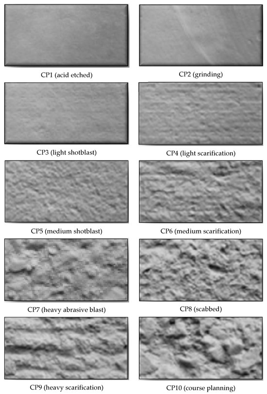
Figure 2.
Demonstration of concrete surface profiles ranging from almost smooth (CSP1) to very rough (CSP10) [124].
In the equation above, c and depend on the surface roughness, is the design tensile strength of the weakest layer, stands for tension caused by the minimum force across the interface that can act with shear at the same time, is the ratio of the reinforcement crossing the interface area and the whole joint area, and is the angle between reinforcement crossing interface and the interface itself [123].
Various devices and methods are commonly deployed for the preparation of the substrate surface, in which the superficial concrete layer is removed and any dust or debris will be eliminated from the surface, including shotblasting, scarifying, sandblasting, grinding, bush-hammering, brushing, chipping, water-jetting, hydro-demolition and in-form retarders, each associated with benefits and drawbacks regarding their cost, time consumption, provided level of roughness and challenges [3,9,125,126]. Some of the approaches have already been proven to promote damage in the substrate, like hammering and needle-gun [126]. The following sections describe the approaches in detail, whose suitability is reported to some extent, including their benefits and the implementation problems that they might cause.
2.4.1. In-Form Retarders
Retarders, as their name implies, are chemical admixtures which can be added to concrete as a percentage of cement mass in order to retard cement hydration and thus concrete setting time. They are helpful in overcoming different challenges, such as casting concrete in hot weather, continuous concrete placement (such as that of mass concrete), and low workability [127]. Retarders are of many types:
- Lignosulfonates, which are ligno-sulfonic aid salts;
- Carboxylic acid salts;
- Some kinds of inorganic salts;
- Some sugar derivatives [128].
ASTM C494 classifies retarders into three groups, B, D and G: true retarding admixtures, water-reducing agents via the retarding of cement hydration, and dispersants, like superplasticizers, respectively [129]. It has been found that class B retarders can be applied on the inner surface of formwork before pouring concrete or can be sprayed on its surface to retard its setting time and hardening. Then, water jets are utilized so as to pressure-wash the surface because of its lower strength and to expose its aggregates, which is a similar strategy to that for producing exposed aggregate concrete (EAC) [11,130]. This method has gained a lot of popularity because of being easily implemented and not causing any microcracks in the hardened concrete [11,131,132]. The proportion of retarder concentration must be selected carefully based on rate of cement setting and desirable level of aggregate exposure [11,133].
De La Varga et al. (2018) investigated three aggregate exposure levels (shown in Figure 3) by different retarder concentrations as an approach to enhance bonding between both concrete-cementitious grout and ultra-high performance concrete (UHPC) and it was found that a higher aggregate exposure leads to a better bond strength, especially in the case of using grouts; however, UHPC connections are not considerably dependent on surface roughening [11]. SEM (scanning electron microscopy) images have also illustrated that two types of interfaces will be formed in the case of aggregate exposure: (1) grout-aggregate (G-A) and (2) grout-paste (G-P) (depicted in Figure 4). The latter has been shown to be more porous than the former and thus creates a weaker bond. Consequently, roughening the surface through aggregate exposure results in a better and more durable connection [112].
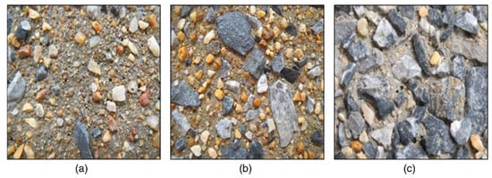
Figure 3.
Level of aggregate exposure due to using in-form retarders: (a) low; (b) moderate; (c) high [11].
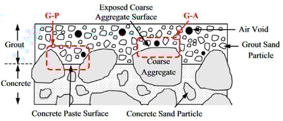
Figure 4.
G-A and G-P in the interface between a concrete and grout layer [112].
2.4.2. Sandblasting
One of the abrasive techniques that can be utilized to increase surface roughness and result in aggregate exposure is sandblasting, which has been in practice and proven to be effective for many years [134,135,136]. This method is favorable because of its adaptability to construction demands, such as attaining different roughness degrees and configurations, depending on the pressure applied on the surface and the time of operation [137]. The common materials used in this method are sand, slag, metallic sand and silica sand [138]. Both wet and dry sand can be used with the same approach and their only difference is that much less dust is produced using wet sand, but in both cases a considerable amount of sand is left behind [139]. Tests have shown that the height of peak-to-valley of irregularities in the roughened concrete is no more than 1 mm [117]. Julio et al. (2004) employed different techniques for investigating their impact on the bond strength of two concrete layers and it was demonstrated that the highest values in both shear and tension were witnessed in the case of sandblasting application because, compared to other methods, it could not only roughen the whole surface, but also make the aggregates exposed [125]. Tayeh et al. (2013) conducted mechanical tests on the bond adhesion of concrete and UHPC and demonstrated that the maximum adhesion is observed when sandblasting is selected instead of wire-brushing, which could only improve bond strength by 40% [120].
2.4.3. Shotblasting or Bead Blasting
Shotblasting is another abrasive measure in which a metal blast wheel, like a steel shot, is applied onto the substrate surface with high velocity to apply centrifugal force and blast off any irregularities from concrete. The finite amount of concrete removed is then vacuumed in the container of the shotblasting machine to be discarded later [8]. Treatment time plays a major role in the degree of roughness using this method. For example, the height of peak-to-valley irregularities for 20 s of treatment is 2 mm, while it will increase significantly up to 7 mm when the time doubles. Formation of cracks is very common in shotblasting and it can even remove the aggregates from the concrete surface, making it the most aggressive method compared to sandblasting, waterblasting and milling [117]. Santos et al. (2011) executed shotblasting, wire-brushing and sandblasting on substrates before adding a new concrete layer and evidenced that shotblasting led to the highest level of roughness and hence the highest bonding shear resistance [55].
2.4.4. Hydro-Demolition
Hydro-demolition, which was first established in Europe, is the practice of employing ultra-high-pressure water jets for removing of any undesirable material from the surface of concrete or disintegrating cement paste without fracturing aggregates and, since it does not cause any vibration, its influence on the intactness of substrate concrete is little, making it a non-aggressive technique for surface preparation. It can also remove concrete around reinforcement without having any destructive impact on it. The degree of demolishing is controllable in this method by changing the water stream pressure and can vary from surface scarification to deep penetration [140]. However, some of its disadvantages include generating a lot of noise, high cost and requiring a considerable amount of clean water [139].
Sakota et al. (2005) indicated that a 5 mm thickness or higher is necessary for the removed concrete by hydro-demolition so as to ensure a sufficiently strong bond between the layers [141]. Habel et al. (2007) studied the effectiveness of hydro-demolition on bond behavior of a composite RC–UHPC specimen and concluded that shear loads could transfer between the layers because of surface roughness [142]. Bond adhesion between concrete slabs and UHPC was studied by Haber et al. (2018) while considering scarification and hydro-demolition as the roughening approaches. Microstructural analysis of the specimens revealed that hydro-demolition outperformed scarification due not only to fewer microcracks, but also to more macrotexture roughness [15].
2.4.5. Waterblasting
Generally, there are two types of waterblasting: without abrasive and with it. In the first, only water with a pressure of 35–105 MPa is sprayed on concrete and the procedure is very similar to hydro-demolition but with much lower water pressure, while in the second, abrasive materials, such as garnet or aluminum oxide, are also added to the water stream in order to expose the fine aggregates of concrete by removing concrete laitance [8]. A comparison between the effectiveness of waterblasting and sandblasting proved that they led to a similar degree of bond strength, while sandblasting caused a higher amount of roughness on the surface [143].
2.4.6. Chipping
Chipping is a method in which the deteriorated surface of the substrate is removed to make it ready for bonding with an overlay or a repairing material. Breaker chisels and pneumatic breakers are used in this regard and they tend to weigh between 10 kg and 30 kg [144]. Austin et al. (1995) found that the bond strength of concrete can be adversely affected by the microcracks formed in the subsurface region of hardened concrete [145]. Tanikura et al. (2017) used X-rays to scan the concrete specimens treated by chipping for the sake of evaluating induced cracks, their width and the porosity of the substrate surface. They also took 3D images to make a comparison between the damage degree of specimens treated with chipping and hydro-demolition and the results confirmed that chipping inflicted much more damage in the concrete [146]. The same result was obtained by many other studies [73,76]; it was also found that it is not suitable for automatic processes in construction [147]; nevertheless, the cheap cost and portability of its machines have led to their popularity compared to other techniques, such as water-jets. This led Sono et al. (2020) to implement a modified chipping pattern, which could control the severity of the damage while improving bond strength. They carried out numerical simulations and illustrated that, when the speed of chisel impact with concrete is higher and sharper, rather than being rounded, fewer cracks are formed. while the angle of impact had a negligible effect on crack propagation [144].
2.4.7. Grinding
In this process, a stone wheel or diamond disc is applied to the concrete surface to remove the cement paste on top of the aggregates to the extent that they become exposed and visible. The ultimate roughness and thus the bond strength can vary depending on the type of wheel and powder applied to it [116]. The fine dust produced by this technique is able to fill the surface pores of the concrete and exacerbate bonding capacity; therefore, the surface has to be cleaned carefully afterwards [139].
Garbacz et al. (2005) used grinding for a uniformly rough surface with no sharp edges or valleys. SEM observations revealed that narrow cracks rarely appeared in the substrate using this method, and this is why grinding was classified as a non-aggressive surface preparation technique compared to sandblasting and shotblasting [117].
2.4.8. Milling or Scarification
Milling is a completely dry operation of removing the top surface of concrete, which can be done either manually or mechanically using machines with diamond-tipped blades. High degrees of irregularities on concrete surface, wide and deep cracks and loose or completely removed aggregates will be witnessed after using this roughening technique [117]. This method is not applicable in the presence of reinforcements near the surface due to the possibility of hitting them, but it is quick and, in the case of being equipped with vacuums, only a slight amount of dust is produced [139].
Overall, Table 1 summarizes the risk of microcracking and substrate damage in the aforementioned surface preparation methods, plus their range of penetration depth. The risk has been classified into three levels, high, moderate and low, and it can differ over a range for some methods based on different parameters, such as applied pressure.

Table 1.
Different surface preparation methods and their cracking risk [117,139,148].
While all of the parameters above play a contributory role in bond strength, their impacts are not equally important. Huang et al. (2019) claimed that surface roughness, compressive strength of overlay concrete and presence of fibers in the overlay are incredibly influential, in order of significance [16]. However, this is not enough and a much more comprehensive study has to be performed to contemplate all of the above mentioned factors as variables and evaluate their degree of effectiveness.
2.5. The Impact of Bonding Agents on Bond Behavior
Bonding agents are adhesive substances that can be utilized for connecting two or more similar or dissimilar materials to each other while contributing to the structural integrity and load bearing [149]. They can be applied onto the clean and normally dry surface of concrete for bonding both fresh and hardened concrete to the substrate layer [3]. While there are a large variety of bonding agents in the market, such as acrylic resins, polyurethanes and epoxy resins, epoxy resins and cement-based slurries are the most prevalent, employed to rehabilitate old structures and connect prefabricated concrete elements. Desirable properties of epoxy as the most popular organic bonding agent, such as low shrinkage, low residual stress and high pull-off strength, makes it an ideal and frequently used option among other resins [150]. Diab et al. (2017) compared three types of bonding agents, namely epoxy, cement mortar and latex paint, and the results of slant shear tests revealed that epoxy could ameliorate shear strength more than other bonding agents [100]. Various studies have shown that adhesion of epoxy to concrete forms a microstructure, which offers numerous positive aspects, such as high modulus of elasticity and mechanical strength, decent thermal stability, low creep, and resistance against chemical erosion [151,152]. Their major drawbacks, however, include being brittle, relatively expensive and having high water absorption. The condition of substrate surface, such as irregularities [125], chemical composition of bonding agent, its application method and environmental variables, like humidity, can highly affect the effectiveness of bonding agent, epoxies in particular [153].
Performance of epoxy in concrete joints in moist and other environmental conditions has been evaluated using different tests and under various loads of shear, tension and their mixture in many studies [85,154,155,156,157]. As an instance, entrance of water into resin composition can lead to plasticization, cracks and hydrolyzation, all of which are harmful for the bond due to the decrease in modulus and strength [158]. One of the other substantial environmental conditions that affects bonding agents is curing temperature. It was shown that a temperature rise from 5 °C to 50 °C decreases the bond strength by a significant value of 65% due to an even faster setting of epoxy compared to fresh concrete at elevated temperatures, which leads to a poor bond at the interface [159]. Furthermore, provided that the compressive strength of the concrete layers is high enough (more than 60 MPa), adhesive failure will occur in the system rather than rupture in the concrete layers, and the presence of the bonding agent will play a key role in bond performance [160].
The thickness of the applied bonding agent layer has to be neither too low, nor too high, because it can lower the bond strength. The bonding agent must be capable of penetrating the surface pores of both layers, not only to lead to a smooth surface, but also to form a stronger connection. When its thickness is low, irregularities in the surface of the substrate will not be filled with bonding agent and pores can act as places where stress concentration occurs and resultant cracks appear. Xiong et al. (2006) used different concentrations of silane coupling agent (SCA) and evidenced that a concentration value of between 0.5% and 1% leads to the best performance [161]. In other research, Newlands et al. (2018) reported a considerable improvement in bond strength with a 2 mm increase in the thickness of bonding agent [162]. However, an optimum value for thickness has not been found yet as it depends on numerous parameters, like loading, substrate and overlay properties, and type of bonding agent [29,158,163].
2.6. Curing Conditions
Curing temperature significantly influences overlay characteristics, such as shrinkage, creep and strength [23]. The two major curing temperatures are normal and high, and the latter has proven to illustrate much more desirable results, such as gaining higher strength and most of its shrinkage in a span of 4–5 days after being cast [55,125]. Delatte et al. (2000) considered three constant ambient temperatures of 4, 21 and 38 °C for high early-strength concrete overlays. They also prepared some specimens to be exposed to sun and others in shade while being cured with plastic and wet cloth to investigate the impact of curing temperature and condition on bond strength development. It was found that both tension and shear strength of concrete are highly dependent on curing conditions, fluctuation of temperature and especially moisture loss, since the specimens in shade illustrated a much higher strength compared to those in sun [164].
Zhang et al. (2020) employed three curing techniques for a UHPC overlay, namely normal curing, steam curing with the temperature of 60 °C and steam curing at 90 °C. It was determined that, although the compressive strength of UHPC rose considerably with high-temperature curing, the increase in the bond shear was negligible in the case of 60 °C and there was a reduction of 13% in the shear capacity of the bond with a curing temperature of 90 °C compared to normal curing. It was concluded that the reason behind such an observation was associated with the high differential shrinkage between overlay and substrate at young ages, which leads to the development of tensile cracking because of being confined by the NC substrate [23].
Nevertheless, curing condition has illustrated a trivial influence on bond behavior compared to other parameters, such as surface roughness. For example, the bond strength between NC–UHPC was tested by Al-Madani et al. (2022) in two curing conditions, water and heat. In water curing, specimens were kept in a water tank for 28 days right after being demolded while, in the heat curing, they were kept at 60 °C for the same period of time. Four different tests were conducted to assess the bond strength, namely bi-surface shear, slant shear, splitting tensile test and three-point flexural test. The obtained results of all tests showed the negligible effect of curing methods on bond strength, except for the case of bi-surface shear, in which the strength of specimens cured by water was 20% higher than that of those cured by heat [165].
Table 2 summarizes the some of the key parameters mentioned and the papers which have evaluated them in certain experimental studies, along with the most commonly highlighted results obtained.
Table 2.
Overview of parameters influencing bond strength between concrete layers.
3. Durability of Concrete-to-Concrete Bond in Extreme Conditions
While concrete-jacketing can solve the problems faced by deteriorated concrete, further damage can jeopardize the potential service life of a retrofitted structure [205]. These damages, which can occur because of different external environmental conditions, such as chemical attack, weathering and passage of time, have to be investigated to ensure a sufficiently durable concrete overlay.
3.1. Freeze–Thaw Cycles
Freeze–thaw (F–T) cycles have proven to incur uneven cracking in concrete whose intensity depends on w/c ratio, additives, aggregates and cooling rate of the environment [205,206]. This damage happens in three stages: firstly, the initial cracks, which already exist in concrete, absorb water from the surroundings and the internal pores of the concrete are filled with water; secondly, the water freezes due to cold temperature and its volume increases by 9%, causing a tensile force in the walls of concrete pores; thirdly, the applied pressure due to water expansion induces cracking and concrete spalling might also occur [207,208,209]. Therefore, it is essential not only to investigate bond durability in cold conditions where F–T cycles are in progress constantly, but also make a wise selection regarding the overlay concrete properties.
There is a wide consensus over the detrimental impact of F–T on bond strength [210,211,212,213]. Tian et al. (2019) found that the shear strength of the bond between NC and engineered cementitious composites (ECC) decreased substantially after being exposed to 300 cycles of freeze and thaw, but this reduction was much lower in the case of a higher strength in ECC [214]. Fan et al. (2021) subjected samples consisting of old and new concrete layers with compressive strength of 30 MPa and 35 MPa, respectively, to 60 consecutive F–T cycles. The splitting tensile test results revealed a sudden drop in bond strength at early stages of the cycles, but this reduction became slow at later stages. The relative modulus of elasticity of specimens also decreased by 40% after experiencing freeze and thaw [215].
However, it was observed that addition of between 5 and 15% silica fume to concrete mix design can improve its durability when being subjected to F–T conditions [216].
3.2. Chemical Attack
Carbon and sulphate attack are amongst the most hazardous aggressive conditions that can compromise the service life of concrete structures and therefore bonded composites [217]. Since the properties of concrete substrate and overlay have proven to be highly effective on the overall bond behavior, utilization of cements, which are suitable for sulphate resistance, can be beneficial [211,218]. Sulphate erosion, which is common among on-shore structures, normally occurs at the same time as dry–wet cycles; hence, Gao et al. (2019) exposed composites of NC–NC and strain-hardening cementitious composites (SHCC)–NC to 120 cycles of sulphate attack and several conclusions were drawn: firstly, selection of SHCC as the overlay had a better performance in terms of bond strength degradation compared to normal concrete; secondly, there was a consistent reduction in the values of bond strength with the increase in the number of cycles, but this reduction was slower in the case of SHCC rather than NC [219].
Unfortunately, the number of studies on the effect of chemical attack on the durability of concrete-to-concrete interface is extremely limited and more experimental research has to be conducted in this regard to provide a deeper understanding of this subject.
3.3. Fire and High Temperatures
Strength softening is one of the impacts of exposure to high temperatures which decreases the load-bearing capacity of concrete to the extent that it fails at temperatures between 550 and 600 °C [220]. This phenomenon occurs as the result of several procedures: evaporation of both capillary and chemically-attached water, initiation of cracking, instability of aggregates and decomposition of cement hydration products [221,222]. Furthermore, different layers of concrete can illustrate different behavior in terms of thermal expansion coefficient, which leads to creep and cracking [223]; hence, elevated temperatures have the potential to endanger bond integrity and lead to the collapse of the entire system.
Abu Sabah et al. (2019) fabricated composites of normal concrete and Green Universiti Sains Malaysia Reinforced Concrete (GUSMRC), which was a newly developed concrete with high mechanical strength, and exposed them to temperatures of 100, 200, 300, 400 and 500 °C for two hours. Concrete spalling at temperatures higher than 400 °C was observed in all specimens; moreover, while the bond strength nosedived substantially by being kept in a furnace, most of the specimens failed at the substrate rather than the interface during pull-off and shear tests, which proves the suitable bond between overlay and NC [224]. In another study, the bond behavior between ECC and a concrete layer with compressive strength of 38 MPa was investigated in high temperatures of up to 800 °C. Two types of tests were carried out for this purpose: firstly, exposing substrate to very hot temperatures and then casting ECC; and secondly, exposing the composite specimens to elevated temperatures. In the first test, a sharp increase was witnessed in the slant shear test results up to a temperature of 200 °C, but bond strength started to decrease in temperatures higher than that. An almost similar result was also obtained in the second testing procedure, which proves that ECC is a suitable candidate for both repairing concrete damaged by fire and prevention of destruction and better bonding in case of being exposed to a fire [225].
Clearly, more research has to be done on microstructural alterations at the interface during a fire and the quick cooling process following it due to firefighting measures. Table 3 summarizes some of the studies that have been conducted on the effect of different harsh environmental conditions and some other variables on the performance of bond between different types of substrate and overlay concrete.
Table 3.
Summary of several studies on durability of bond in different environmental conditions.
4. Types of Tests Carried out on Concrete Bond
4.1. Surface Roughness Tests
There are different approaches that can be employed for determining the surface roughness in a quantitative or qualitative manner. These methods can contribute to obtaining a more detailed correlation between surface roughness and bond strength at the interface in order to assess the efficiency of surface preparation techniques and make a comprehensive comparison among them. Furthermore, a standardized roughness definition can be established to be applied in real construction projects and emulative concrete connections. For this purpose, different roughness parameters have been developed over the years to provide a quantitative description of roughness and the most prevalent and simplest one is that denotes average roughness, which is the deviation of surface profile from the optimized mean plane, and is expressed by
where:
is the value of peaks and valleys from the optimized plane obtained from MATLAB or other software in millimeters or inches according to the unit system, and is the number of discrete points measured [21,137,226].
Some of the best methods for surface roughness characterization that can provide a quantitative measurement and have already been validated in the previous articles, besides their benefits and drawbacks, will be discussed in the following section.
4.1.1. Sand Patch Method
In this test, which is one of the simplest, a specific amount of calibrated sand is spread over the surface of substrate in the form of a circle and the area which is covered by it (diameter of circular region) is measured in order to determine the mean texture depth (), which represents the level of surface roughness:
where stands for the volume of spread sand (mm3) and is the diameter of the circular region covered by sand (mm) [227].
The biggest drawback of this approach is its limitation in being employed in horizontal and top surfaces only. It is worth mentioning that macro-texture is the only parameter that can be investigated using sand patch test, and not micro-texture [137].
4.1.2. Circular Texture Meter (CT Meter)
This method can be utilized to calculate the mean profile depth (MPD) of the surface using a laser displacement sensor attached to a computer and a moving arm, which does not have any contact with the specimen and therefore is categorized as a non-destructive method [226,228]. Human error and data scatter are much rarer in this method compared to sand patch, and it is also quick and can be conducted even when there is light deficiency; however, it is considered an expensive technique with a high cost of maintenance [137,229,230].
4.1.3. 2D and 3D Laser Roughness Analyzer (LRA) Method
This method uses a laser scanner in order to prepare a 3D or 2D image that is taken from the surface of the specimen’s substrate (Figure 5). The image is then imported to MATLAB by selected points to obtain a 2D or 3D representation of the peaks and valleys of the surface plus an optimized plane along the surface length, which crosses peaks and valleys and, finally, Ra is calculated. This method is ideal because of being in situ, completely non-destructive and relatively fast compared to Processing of Digital Images (PDA), which extracts small samples from concrete elements and hence destroys them partially [131,137].
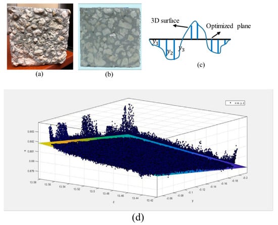
Figure 5.
Configuration of laser Roughness Analyzing method. (a) Test specimen; (b) scanned surface; (c) defining Ra; (d) 3D image of peaks and valleys compared to optimized plane [21].
4.2. Characterization Methods for Assessing Bond Properties
There are various tests which can be carried out to investigate the characteristics of concrete-to-concrete interface and measure the bond strength, which fall into two major categories:
(1) Microstructural analysis.
(2) Tension, shear and shear and compression-based tests for measuring shear resistance of bond [36].
Each of the tests reveal a particular aspect of bond performance and have their own pros and cons, which will be discussed in the following section.
4.2.1. Microstructural Analysis (MSA)
The connection area of concrete elements can be characterized using expensive, yet precise, microscopy. In this approach, an electron (electron microscopy) or light beam (optical microscopy) is utilized to scan a concrete body at a scale of nanometers. The most common methods in this case are SEM and TEM (Transmission Electron Microscopy), in which external and internal morphology of a specimen are assessed, respectively. While both methods apply electron beams to the surface, the former measures the number of electrons that scatter back, therefore giving information about the surface, and the latter measures the changes in electrons that scatter in the body in order to investigate the internal microstructure. SEM is a suitable method for analyzing surface roughness, while TEM is an appropriate technique for analyzing microcracking effects at the interface [137,231,232]. Image magnification can range from 100× to 500× for general interpretation of interface and quantifying it in a detailed way, respectively. After taking images, quantitative image analysis is carried out so as to collect backscatter electron (BSE) mapping and interpret the data based on gray levels [108,112,233,234].
De La Varga et al. (2018) used SEM analysis for investigation of the fracture surfaces of grout–concrete composites, which had experienced bond failure by being subjected to pull-off tests. SEM images could give them a better understanding of surface porosity and how bond performance can be improved [112]. Haber et al. (2018) conducted MSA using SEM on the bond between UHPC overlays and concrete bridge decks to obtain more information about UHPC consolidation and the surface condition of the concrete substrate. They found out that air voids and debris were the major reasons behind non-contact areas between overlay and substrate and this is caused by low consolidation. Moreover, more microcracks were observed in the specimens whose surfaces were roughened using scarification rather than those by hydro-demolition [15].
4.2.2. Measuring Bond Resistance
There are various and sundry tests available to measure the bond strength and its failure mechanism. Figure 6 summarizes some of these tests in terms of their specimen shape and loading. They differ from each other based on their set-up, specimen configuration, applied load and so forth. That being said, they are categorized into three major groups: tension, shear and mixed tests. It is also worth mentioning that normally, the shear strength of the bond is governed by surface roughness while the tensile strength of the bond is affected by hydration products at the interface [112]. The suitable test has to be selected based on the types of stresses that are induced in the bond between layers in the structure in the field and during its service life [36,121]. Zanotti and Randl (2019) discussed that determining the bond strength merely based on conducting one type of test ushers in misleading results and various test set-ups have to be combined to achieve reliable findings [70].
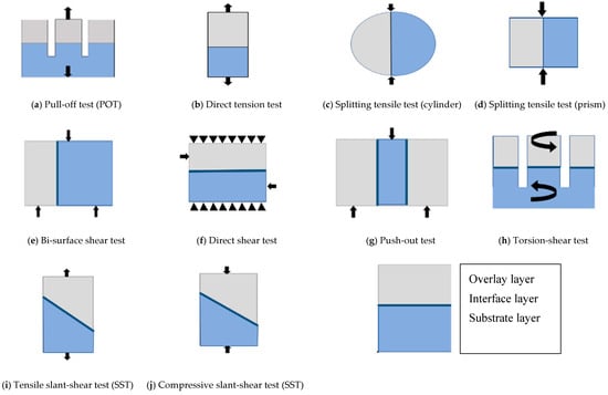
Figure 6.
Specimen and loading configuration of different bond strength tests [6].
Tension Tests
The tension tests for investigation of bond strength comprise of pull-off, direct and indirect-tension tests in which the propagation of tensile stress in the interface plane causes failure in the specimen [36]. The most common ones are discussed in the following:
(a) Pull-off test (POT)
The difficulty in performing a precise direct tension test, Figure 6b, due to high chances of eccentricity and hence challenges in interpretation of the results led to introduction of pull-off test which can be conducted both on-site [235,236] and in the laboratory more easily. Testing set-up which is illustrated in Figure 6a shows loading protocol and specimen geometry. The specimens are derived by drilling a cylindrical core with the diameter of 75 mm and the height of 15 mm below the interface in substrate layer in concrete samples and a steel disc is glued to their upper surface in order to apply tensile force [237], however, similar problem of a large scatter in the results obtained due to misalignment and geometry of interface exists in this case as well [24] plus some other challenges such as the risk of damage by drilling and inappropriate attachment of disks to concrete surface [6]. The results in this test are not affected by friction or any force other than tension and that is why they are very conservative and the obtained bond strength using this method is far less than other techniques such as shear tests [36]. Lastly, the frequent mode of failure witnessed in this test is substrate fracture which makes the results unreliable because it is not the real interface strength [70].
Delatte et al. (2000) modified pull-off test by placing a bolt into concrete overlay before being cast so that the steel discs for carrying out the test would be attached to the bolt rather than being glued to concrete directly. This approach has multiple benefits such as being more rapid and ensuring failure at the interface instead of steel cap debonding [164]. Valipour and Khayat (2020) also proposed a modified version of pull-off test for overcoming the same challenges. Before casting the overlay, a PVC tube with the same size of specimens that have to be cored was inserted to eradicate the need of coring and the consequent damage. Also, the direct contact area between the concrete layers is reduced using a metal washer to ensure that the stress concentration is subjected to the interface and not elsewhere [238].
Rith et al. (2016) used pull-off tests for determining the factors that might cause a poor connection or debonding between old and new concrete in bridges and a total number of 166 tests were carried out, illustrating a strength of between 0.2 and 2.95 MPa [172].
(b) Splitting tensile tests (SST)
The splitting test was first introduced by Akazawa (1943) [239] and modified and developed later by Carneiro et al. (1953) [240]. This test set-up can be conducted on specimens with both cylindrical (Figure 6c) and cubic, or prism, shapes (Figure 6d) while a compressive force is applied to their side [241]. The compression load forms biaxial stresses in the specimen where the lateral ones are tensile and the vertical ones are compressive [242]. A factor of 0.738 and 0.96 for compressive and splitting tensile strength, respectively, are suggested to convert cubic specimens’ results to cylindrical ones [243]. This test has been standardized by ASTM C496 and does not have the same issues as the pull-off test [36]. However, the results obtained by this method have a higher value and seem to be overestimated to some extent [70]. The contributory factors to bond strength measured by this method are the compressive and tensile strength of substrate and overlay, but surface preparation methods do not influence the results significantly [243].
Momayez et al. (2004) selected cubical splitting tensile test in order to measure the bond strength between concrete layers and the validity of this test method was proven due to the consistency of the obtained results [36,48]. Nonetheless, Santos et al. (2011) adopted the cubic splitting test for assessing the bond strength of RC members in tension. No clear relation was found between the bond strength and the change in surface roughness and concrete layer age and that is why the splitting test was assumed to be inconclusive and unsuitable [55]. Zanotti et al. (2019) compared the results of cylindrical splitting tensile test, push-out, pull-off and slant shear tests with each other for different kinds of concrete layers for normal, high-strength and fiber reinforced concrete. It was concluded that the bond strength derived from shear and tensile tests cannot be easily compared with each other because of being differently affected by interfacial parameters; however, the results achieved from splitting tensile test can be utilized for comparing other test setups. They also came up with constants, i.e., the cohesion-tensile bond ratio, based on different concrete strengths, which takes the splitting tensile test results as reference and makes a comparison between them and the shear test results [70].
Shear Tests
The shear tests that can be conducted to measure bond strength include bi-surface shear, torsion-shear, L-shaped, direct shear and push-off tests [167,244]. Stress concentration in the interface edge in these tests makes them unfavorable to some [245], yet two of the most common examples are discussed below.
(a) Bi-surface shear test
The bi-surface shear test, as illustrated in Figure 6e, uses cubic specimens, which will come under pressure using three steel plates that are placed on the top and bottom surface of the concrete, forming two shear planes, one in the interface and the other in the substrate. Standard 153 mm cubic specimens according to ASTM C39 [246] can be prepared for this purpose, while a layer of new concrete with different thicknesses (normally a third of the volume) is added to them [21].
This test is advantageous in several aspects: firstly, since the loads applied are only those of compression, the omnipresent universal testing machine (UTM) can be utilized and there will be no need for fabrication of a new apparatus. Secondly, bending tensions will not be formed due to symmetrical loading, and shear resistance of the bond can be measured independently; lastly, as for the standard-size cubic specimens, the already existing molds are good enough for making specimens [3]. However, moisture content and surface preparation play a major role in the results obtained by this method [108]. A finite element analysis was carried out to prove the suitability of the bi-surface shear test, in which how normal and shear stresses were distributed along the interface of concrete layers with different stiffnesses was evaluated. It was shown that the differential stiffness of concrete has almost no impact on the shear stress and this is a desirable feature because the growth of differential stiffness leads to stress concentration in the interface zone and can change the failure mode, so insensitivity of the bi-surface shear test to the concrete mixture makes it an appropriate tool for assessing bond strength [3].
Lee et al. (2016) who used this test setup in order to investigate the effect of casting delay on bond behavior, concluded that there was a roughly 10% difference in the values of bonding shear in the specimens that failed at the interface and the ones which failed elsewhere [247]. Al-Rubaye et al. (2020) found that the bond strength obtained by the slant shear test is 2–3 times higher than that of the bi-surface shear test [248].
(b) Push-out test
The push-out test, also known as push-through cube, uses symmetrical specimens as depicted in Figure 6g that have two interfaces and are subjected to symmetrical loading, which causes pure shear in the interface without any bending moments or stress concentration at specific points [249]. The two major failure modes that are possible in this test are interface failure due to shear or tear, and failure of one of the substrate layers because of compression. One of the benefits of this test is that no mechanical connector will be needed to transfer compressive load to the specimen [195]. Having two interfacial planes rather than just one is referred to as one of the disadvantages of this test because of being contradictory to most site conditions, in which the overlay is cast on one layer of concrete [24]. The attained results are typically low in comparison with the slant-shear test because of lack of any compression, and therefore frictional/interlocking mechanisms, at the interface [70].
Wang et al. (2017) investigated the shear bond strength between NC and ultra-high toughness cementitious composite (UHTCC) using push-out tests and concluded that the major parameters affecting the results are surface preparation, concrete strength and type of bonding agent [249].
Shear and Compression Tests
(a) Slant shear test
The slant shear test is the most common type of experimental test in which shear and compression are combined and the configuration of samples is either a square prism, which is halved into two identical parts at a 30 degree angle, or a cylinder composed of two concretes, which bond diagonally at a 60 degree angle and is subjected to compressive (Figure 6j) or in some cases tensile (Figure 6i) loads [100]. Two principle stresses are formed in the interface as a result of loading: one of which is parallel (shear) and the other is perpendicular (compression) to the bond, and they are shown in Equations (6) and (7), respectively [36].
where:
is the compression load, is the interface angle from vertical axis and is the cross-sectional area to which the loading is applied.
It has been reported that this test is sensitive to surface roughness [126,192,250,251]. The results of bond strength using four different kinds of surface preparation methods by slant shear and pull-off tests are demonstrated in Figure 7. The 150% increase in bond strength in shear and compression by application of a suitable surface roughness technique proves the sensitivity of the slant shear test to substrate surface conditions [192]. One of the other factors governing the failure mode of the specimens tested is the angle of interface plane from a vertical direction. Zambas (1992) found that this angle has to be smaller than 40° to result in failure at the interface because otherwise concrete crushing will occur in the weaker concrete and the bond strength cannot be measured accurately [252], and this is why 60° from the horizontal line has been specified by ASTM C882/C882M-20 [253]. The compressive load applied in slant shear increases the friction between concrete surfaces and illustrates a higher strength in the bond, which might not necessarily replicate the real performance of a concrete bond under pure shear [21].
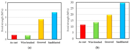
Figure 7.
Comparison of bond strength values for different surface preparation methods (a) conducted by slant shear test; (b) conducted by pull-off test [193].
Julio et al. (2004) determined a variation coefficient for the bond strength results obtained from slant shear and pull-off tests as a tool for comparison and concluded that an increase in the bond strength results in a drop in the value of variation coefficient, but no relation could be found between these two variables in the case of pull-off tests [125]. Hu et al. (2019) decided to experimentally evaluate the performance of concrete bond under dynamic slant shear, rather than the static one which had been previously studied. The split Hopkinson pressure bar (SHPB) was chosen in order to apply different dynamic loading protocols to the 95 cylindrical specimens made and the interface roughness was improved using rectangular grooves on the old concrete. They selected two different interface angles of 60 and 50° and, due to the fact that the probability of being subjected to dynamic loads for structures is low at early ages and normally occurs during the service life, 60 and 120 days were selected as the interface ages of the specimens. They found that interface failure was more likely with the slant angle of 60° regardless of loading rate. They also concluded that, when the strain rates which correspond to loading rates increase, bond strength also rises significantly [254].
5. Summary and Conclusions
While there are many methods for retrofitting of concrete structures, such as sealing cracks, water proofing or structural strengthening, adding a fresh layer of concrete to the already existing ones, also known as concrete jacketing, is very common. Moreover, non-continuous casting in large projects with high concrete volume is another case in which a bond will form between concrete layers. Hence, integrity and durability of this bond is essential for the sake of having a desirable concrete-to-concrete connection and ensuring structural safety. A large number of factors can influence the bond quality, which have to be thoroughly investigated. These factors, however, can become confusing and challenging to be taken into consideration simultaneously. Hence, this paper provides a full review of the literature concerning different concrete properties that can impact bond characteristics, available tests conducted for measuring bond strength between concrete layers and the surface preparation methods utilized for improving the bond. The following part chronicles the main findings mentioned in this paper:
- There are three different failure mechanisms that can take place in a concrete-to-concrete connection, i.e., adhesive, cohesive and mixed, among which the cohesive is preferable since it allows the full usage of structural capacity, and making a suitable bond between concrete layers can effectively prevent the adhesive failure which occurs in the bond.
- Bond strength is highly influenced by the properties of both concrete layers, such as their compressive strength, age, level of shrinkage, thickness and types of aggregates. The curing conditions of concrete substrate and overlay, such as temperature and moisture, also impact the bond performance to a great extent.
- Bonding between concrete layers in construction techniques where two layers of concrete are cast at different times, such as the prefabrication of structural elements and connecting them by grouting the void between them by fresh concrete, can be improved to ensure that a brittle bond failure does not jeopardize the entire structure safety and service life.
- While surface preparation techniques, which comprise cleaning, roughening and deteriorated concrete removal, are used to enhance bond shear resistance, bond agents can be applied on the surface to make an even stronger connection between concrete layers.
- Various tests encompassing microstructural and mechanical types are available to measure the bond strength, including microscopy, push-off, push-out, bi-shear, slant shear tests and so forth, with different setups and specimen configurations. An appropriate one must be selected by considering the concrete element properties, such as direction, loading, support conditions and bonding complexity. Nevertheless, it is recommended to specify an average bond strength by using multiple test types to obtain more precise and representative results.
6. Recommendations for Future Studies
Taking all of the research that has been conducted so far and collected in this review into account, the following part proposes future research prospects both for improving and evaluating the bond performance between old and new concrete layers:
- Evaluation of performance changes in different bond configurations, such as more than two layers of concrete, and anchored by various mechanical connectors.
- Developing a mechanical apparatus for examining the bond strength under the combined effect of tension, torsion and shear or compression, torsion and shear.
- A comprehensive comparison between the effect of different kinds of bond agents and the criteria for selecting the most suitable one according to the case study.
- The effect of overlay thickness by measuring the bond strength for various thicknesses on both rough and smooth substrates and different bond strength tests.
- Long-term performance of concrete-to-concrete bond during the service life of the structure.
- Bond performance under cyclic loads
- Bond strength between concrete and non-shrink grouts that are common in accelerated bridge technology (ABC) and other prefabrication practices
- Developing a numerical model by machine learning based on existing literature and new experimental results to predict bond shear strength based on features of substrate and overlay, such as roughness, relative humidity, strength, etc.
Author Contributions
Conceptualization, S.M. and M.H.; methodology, S.M. and M.H.; writing—original draft preparation, S.M.; writing—review and editing, M.H.; visualization, S.M.; supervision, M.H. All authors have read and agreed to the published version of the manuscript.
Funding
This research received no external funding.
Data Availability Statement
The data supporting the findings of this study are available from the corresponding author upon request.
Conflicts of Interest
The authors declare no conflict of interest.
References
- ARTBA Bridge Report. American Road and Transportation Builders Association, Washington, DC, USA. 2022. Available online: https://artbabridgereport.org/ (accessed on 5 April 2024).
- Vaysburd, A.M.; Emmons, P.H. Concrete repair a composite system: Philosophy, engineering and practice. Restor. Build. Monum. Bauinstandsetz. Baudenkmalpflege 2006, 12, 423–436. [Google Scholar]
- Santos, D.S.; Santos, P.M.D.; Dias-da-Costa, D. Effect of surface preparation and bonding agent on the concrete-to-concrete interface strength. Constr. Build. Mater. 2012, 37, 102–110. [Google Scholar] [CrossRef]
- Rabehi, B.; Ghernouti, Y.; Li, A.; Boumchedda, K. Comparative behavior under compression of concrete columns repaired by fiber reinforced polymer (FRP) jacketing and ultra high-performance fiber reinforced concrete (UHPFRC). J. Adhes. Sci. Technol. 2014, 28, 2327–2346. [Google Scholar] [CrossRef]
- Cusson, D. Durability of repaired concrete structures. In Failure, Distress and Repair of Concrete Structures; Elsevier: Amsterdam, The Netherlands, 2009; pp. 296–321. [Google Scholar]
- Pulkit, K.; Saini, B.; Chalak, H. Effect of various interface bond tests and their failure behavior on substrate and overlay concrete —A Review. Res. Eng. Struct. Mater. 2023. [Google Scholar] [CrossRef]
- Stander, H. Interfacial Bond Properties for ECC Overlay Systems. Ph.D. Thesis, University of Stellenbosch, Stellenbosch, South Africa, 2007. [Google Scholar]
- Courard, L.; Bissonnette, B.; Garbacz, A.; Vaysburd, A.M.; Von Fay, K.F. Guidelines for concrete surface preparation: 10 years research and experience. MATEC Web Conf. 2018, 199, 08004. [Google Scholar] [CrossRef][Green Version]
- Soares, S.; Sena-Cruz, J.; Cruz, J.R.; Fernandes, P. Influence of Surface Preparation Method on the Bond Behavior of Externally Bonded CFRP Reinforcements in Concrete. Materials 2019, 12, 414. [Google Scholar] [CrossRef]
- Carbonell Muñoz, M.A.; Harris, D.K.; Ahlborn, T.M.; Froster, D.C. Bond performance between ultrahigh-performance concrete and normal-strength concrete. J. Mater. Civ. Eng. 2014, 26, 04014031. [Google Scholar] [CrossRef]
- De la Varga, I.; Haber, Z.B.; Graybeal, B.A. Enhancing Shrinkage Properties and Bond Performance of Prefabricated Bridge Deck Connection Grouts: Material and Component Testing. J. Mater. Civ. Eng. 2018, 30, 04018053. [Google Scholar] [CrossRef]
- Randl, N. Investigations on Transfer of Forces between Old and New Concrete at Different Joint Roughness. Ph.D. Thesis, University of Innsbruck, Innsbruck, Austria, 1997. [Google Scholar]
- Bonaldo, E.; Barros, J.A.; Lourenço, P.B. Bond characterization between concrete substrate and repairing SFRC using pull-off testing. Int. J. Adhes. Adhes. 2005, 25, 463–474. [Google Scholar] [CrossRef]
- Júlio, E.N.B.S.; Branco, F.A.B.; Silva, V.D.; Lourenço, J.F. Influence of added concrete compressive strength on adhesion to an existing concrete substrate. Build. Environ. 2006, 41, 1934–1939. [Google Scholar] [CrossRef]
- Haber, Z.B.; Munoz, J.F.; De La Varga, I.; Graybeal, B.A. Bond characterization of UHPC overlays for concrete bridge decks: Laboratory and field testing. Constr. Build. Mater. 2018, 190, 1056–1068. [Google Scholar] [CrossRef]
- Huang, H.; Yuan, Y.; Zhang, W.; Gao, Z. Bond behavior between lightweight aggregate concrete and normal weight concrete based on splitting-tensile test. Constr. Build. Mater. 2019, 209, 306–314. [Google Scholar] [CrossRef]
- Costa, H.; Carmo, R.; Júlio, E. Influence of lightweight aggregates concrete on the bond strength of concrete-to-concrete interfaces, Constr. Constr. Build. Mater. 2018, 180, 519–530. [Google Scholar] [CrossRef]
- Manawadu, A.; Qiao, P.; Wen, H. Characterization of Substrate-to-Overlay Interface Bond in Concrete Repairs: A Review, Constr. Constr. Build. Mater. 2023, 373, 130828. [Google Scholar] [CrossRef]
- Randl, N.; Steiner, M.; Peyerl, M. Sustainable strengthening of RC members with high performance concrete overlays. In Maintenance, Monitoring, Safety, Risk and Resilience of Bridges and Bridge Networks; CRC Press: Boca Raton, FL, USA, 2016; Volume 370. [Google Scholar]
- Feng, S.; Xiao, H.; Liu, R.; Liu, M. The bond properties between ultra-high-performance concrete and normal strength concrete substrate: Bond macro-performance and overlay transition zone microstructure. Cem. Concr. Compos. 2022, 128, 104436. [Google Scholar] [CrossRef]
- Valikhani, A.; Jahromi, A.J.; Mantawy, I.M.; Azizinamini, A. Experimental evaluation of concrete-to-UHPC bond strength with correlation to surface roughness for repair application. Constr. Build. Mater. 2020, 238, 117753. [Google Scholar] [CrossRef]
- Iavarone, F.; Vecchio, F.J.; Plizzari, G.; Minelli, F. Shear bond between existing concrete and high-strength fiber reinforced overlay: Influence of substrate strength and interface roughness. Struct. Concr. 2023, 25, 526–536. [Google Scholar] [CrossRef]
- Zhang, Y.; Zhang, C.; Zhu, Y.; Cao, J.; Shao, X. An experimental study: Various influence factors affecting interfacial shear performance of UHPC-NSC. Constr. Build. Mater. 2020, 236, 117480. [Google Scholar] [CrossRef]
- Beushausen, H.; Alexander, M.G. Bond strength development between concretes of different ages. Mag. Concr. Res. 2008, 60, 65–74. [Google Scholar] [CrossRef]
- Momani, Y.; Alawadi, R.; Taqieddin, Z.N.; Tarawneh, A.; Rezeq, W.; Aljuneidi, A. Bond strength prediction of UHPC-NSC interface. J. Appl. Eng. Sci. 2023, 21, 618–628. [Google Scholar] [CrossRef]
- Moelich, G.; Kruger, P.; Combrinck, R. The effect of restrained early age shrinkage on the interlayer bond and durability of 3D printed concrete. J. Build. Eng. 2021, 43, 102857. [Google Scholar] [CrossRef]
- Wu, L.; Farzadnia, N.; Shi, C.; Zhang, Z.; Wang, H. Autogenous shrinkage of high performance concrete: A review. Constr. Build. Mater. 2017, 149, 62–75. [Google Scholar] [CrossRef]
- Beushausen, H.; Alexander, M.G. Failure mechanisms and tensile relaxation of bonded concrete overlays subjected to differential shrinkage. Cem. Concr. Res. 2006, 36, 1908–1914. [Google Scholar] [CrossRef]
- Daneshvar, D.; Behnood, A.; Robisson, A. Interfacial bond in concrete-to-concrete composites: A review. Constr. Build. Mater. 2022, 359, 129195. [Google Scholar] [CrossRef]
- Silfwerbrand, J. Stresses and strains in composite concrete beams subjected to differential shrinkage. Struct. J. 1997, 94, 347–353. [Google Scholar]
- Qin, R.; Hao, H.; Rousakis, T.; Lau, D. Effect of shrinkage reducing admixture on new-to-old concrete interface. Compos. Part B Eng. 2019, 167, 346–355. [Google Scholar] [CrossRef]
- Burkart, I.; Müller, H.S. Creep and shrinkage characteristics of ultra high strength concrete (UHPC). In Proceedings of the Second International Symposium on Ultra High Performance Concrete, Kassel, Germany, 5–7 March 2008; pp. 469–476. [Google Scholar]
- Toledo, W.K.; Davila, L.; Al-Basha, A.J.; Newtson, C.M.; Weldon, B.D. Assessment of Ultra-High Performance Concrete Overlays on Concrete Bridge Decks. In Proceedings of the Tran-SET 2020, American Society of Civil Engineers, Albuquerque, New Mexico, 1–2 September 2021; pp. 278–286. [Google Scholar] [CrossRef]
- Padavala, S.S.A.B.; Kode, V.R.; Dey, S. Bond strength of fly ash and silica fume blended concrete mixes. Asian J. Civ. Eng. 2024, 25, 895–909. [Google Scholar] [CrossRef]
- Mazloom, M.; Ramezanianpour, A.A.; Brooks, J.J. Effect of silica fume on mechanical properties of high-strength concrete. Cem. Concr. Compos. 2004, 26, 347–357. [Google Scholar] [CrossRef]
- Momayez, A.; Ehsani, M.R.; Ramezanianpour, A.A.; Rajaie, H. Comparison of methods for evaluating bond strength between concrete substrate and repair materials. Cem. Concr. Res. 2005, 35, 748–757. [Google Scholar] [CrossRef]
- Kuroda, M.; Watanabe, T.; Terashi, N. Increase of bond strength at interfacial transition zone by the use of fly ash. Cem. Concr. Res. 2000, 30, 253–258. [Google Scholar] [CrossRef]
- Yamei, Z.; Wei, S.; Lianfei, S. Mechanical Properties of High Performance Concrete Made with High Calcium High Sulfate Fly Ash. Cem. Concr. Res. 1997, 27, 1093–1098. [Google Scholar] [CrossRef]
- Al-Azzawi, M.; Yu, T.; Hadi, M.N.S. Factors Affecting the Bond Strength Between the Fly Ash-based Geopolymer Concrete and Steel Reinforcement. Structures 2018, 14, 262–272. [Google Scholar] [CrossRef]
- Li, G. A new way to increase the long-term bond strength of new-to-old concrete by the use of fly ash. Cem. Concr. Res. 2003, 33, 799–806. [Google Scholar] [CrossRef]
- Phoo-ngernkham, T.; Sata, V.; Hanjitsuwan, S.; Ridtirud, C.; Hatanaka, S.; Chindaprasirt, P. High calcium fly ash geopolymer mortar containing Portland cement for use as repair material. Constr. Build. Mater. 2015, 98, 482–488. [Google Scholar] [CrossRef]
- Kramar, S.; Šajna, A.; Ducman, V. Assessment of alkali activated mortars based on different precursors with regard to their suitability for concrete repair. Constr. Build. Mater. 2016, 124, 937–944. [Google Scholar] [CrossRef]
- Tasong, W.A.; Lynsdale, C.J.; Cripps, J.C. Aggregate-cement paste interface. II: Influence of aggregate physical properties. Cem. Concr. Res. 1998, 28, 1453–1465. [Google Scholar] [CrossRef]
- Caliskan, S.; Karihaloo, B.L.; Barr, B.I.G. Study of rock–mortar interfaces. Part II: Strength of interface. Mag. Concr. Res. 2002, 54, 463–472. [Google Scholar] [CrossRef]
- Caliskan, S.; Karihaloo, B.L. Effect of Surface Roughness, Type and Size of Model Aggregates on the Bond Strength of Aggregate/Mortar Interface. Interface Sci. 2004, 12, 361–374. [Google Scholar] [CrossRef]
- Kozul, R.; Darwin, D. Effects of Aggregate Type, Size, and Content on Concrete Strength and Fracture Energy; University of Kansas Center for Research, Inc.: Lawrence, KS, USA, 1997. [Google Scholar]
- Akçaoğlu, T.; Tokyay, M.; Çelik, T. Effect of coarse aggregate size on interfacial cracking under uniaxial compression. Mater. Lett. 2002, 57, 828–833. [Google Scholar] [CrossRef]
- Momayez, A.; Ramezanianpour, A.A.; Rajaie, H.; Ehsani, M.R. Bi-surface shear test for evaluating bond between existing and new concrete. Mater. J. 2004, 101, 99–106. [Google Scholar]
- Chen, B.; Liu, J. Effect of aggregate on the fracture behavior of high strength concrete. Constr. Build. Mater. 2004, 18, 585–590. [Google Scholar] [CrossRef]
- Popovics, S. Strength and Related Properties of Concrete: A Quantitative Approach; John Wiley & Sons: Hoboken, NJ, USA, 1998. [Google Scholar]
- Dehghan, A.; Maher, M.L.J.; Navarra, M. The Effects of Aggregate Properties on Concrete Mix Design and Behaviour. In Canadian Society of Civil Engineering Annual Conference; Springer: Berlin/Heidelberg, Germany, 2021; pp. 457–468. [Google Scholar]
- Yazdi, M.A.; Dejager, E.; Debraekeleer, M.; Gruyaert, E.; Van Tittelboom, K.; De Belie, N. Bond strength between concrete and repair mortar and its relation with concrete removal techniques and substrate composition. Constr. Build. Mater. 2020, 230, 116900. [Google Scholar] [CrossRef]
- Kaplan, M.F. Flexural and compressive strength of concrete as affected by the properties of coarse aggregates. J. Proc. 1959, 55, 1193–1208. [Google Scholar]
- Morimoto, H.; Koyanagi, W. 12 Estimation of Stress Relaxation in Concrete at Early Ages. In Thermal Cracking in Concrete at Early Ages: Proceedings of the International RILEM Symposium; CRC Press: Boca Raton, FL, USA, 1994; p. 95. [Google Scholar]
- Santos, P.M.D. Factors Affecting Bond between New and Old Concrete. ACI Mater. J. 2011, 108, 449–456. [Google Scholar]
- ACI 318R-08; Building Code Requirements for Structural Concrete and Commentary. ACI—American Concrete Institute: Farmington Hills, MI, USA, 2008.
- CSA A23.3; Design of Concrete Structures. Canadian Standards Association, Toronto, ON, Canada, 2004.
- Shaw, D.M.; Sneed, L.H. Interface shear transfer of lightweight-aggregate concretes cast at different times. PCI J. 2014, 59, 130–144. [Google Scholar] [CrossRef]
- Lura, P.; Jensen, O.M.; van Breugel, K. Autogenous shrinkage in high-performance cement paste: An evaluation of basic mechanisms. Cem. Concr. Res. 2003, 33, 223–232. [Google Scholar] [CrossRef]
- Costa, H.; Júlio, E.; Lourenço, J. New approach for shrinkage prediction of high-strength lightweight aggregate concrete. Constr. Build. Mater. 2012, 35, 84–91. [Google Scholar] [CrossRef]
- Teng, L.; Khayat, K.H. Effect of overlay thickness, fiber volume, and shrinkage mitigation on flexural behavior of thin bonded ultra-high-performance concrete overlay slab. Cem. Concr. Compos. 2022, 134, 104752. [Google Scholar] [CrossRef]
- Safdar, M.; Matsumoto, T.; Kakuma, K. Flexural behavior of reinforced concrete beams repaired with ultra-high performance fiber reinforced concrete (UHPFRC). Compos. Struct. 2016, 157, 448–460. [Google Scholar] [CrossRef]
- Teng, L.; Valipour, M.; Khayat, K.H. Design and performance of low shrinkage UHPC for thin bonded bridge deck overlay. Cem. Concr. Compos. 2021, 118, 103953. [Google Scholar] [CrossRef]
- Pulkit, K.; Saini, B.; Chalak, H.D. Factors Affecting the Bond Between Substrate-Overlay Material. A Review. J. Eng. Sci. Technol. Rev. 2022, 15, 55–69. [Google Scholar] [CrossRef]
- Marchment, T.; Sanjayan, J.; Xia, M. Method of enhancing interlayer bond strength in construction scale 3D printing with mortar by effective bond area amplification. Mater. Des. 2019, 169, 107684. [Google Scholar] [CrossRef]
- Megid, W.A.; Khayat, K.H. Effect of structural buildup at rest of self-consolidating concrete on mechanical and transport properties of multilayer casting. Constr. Build. Mater. 2018, 196, 626–636. [Google Scholar] [CrossRef]
- Secrieru, E.; Khodor, J.; Schröfl, C.; Mechtcherine, V. Formation of lubricating layer and flow type during pumping of cement-based materials. Constr. Build. Mater. 2018, 178, 507–517. [Google Scholar] [CrossRef]
- Zanotti, C.; Borges, P.H.; Bhutta, A.; Banthia, N. Bond strength between concrete substrate and metakaolin geopolymer repair mortar: Effect of curing regime and PVA fiber reinforcement. Cem. Concr. Compos. 2017, 80, 307–316. [Google Scholar] [CrossRef]
- Banthia, N.; Zanotti, C.; Sappakittipakorn, M. Sustainable fiber reinforced concrete for repair applications. Constr. Build. Mater. 2014, 67, 405–412. [Google Scholar] [CrossRef]
- Zanotti, C.; Randl, N. Are concrete-concrete bond tests comparable? Cem. Concr. Compos. 2019, 99, 80–88. [Google Scholar] [CrossRef]
- Zanotti, C.; Rostagno, G.; Tingley, B. Further evidence of interfacial adhesive bond strength enhancement through fiber reinforcement in repairs. Constr. Build. Mater. 2018, 160, 775–785. [Google Scholar] [CrossRef]
- Valikhani, A.; Jahromi, A.J.; Mantawy, I.M.; Azizinamini, A. Effect of mechanical connectors on interface shear strength between concrete substrates and UHPC: Experimental and numerical studies and proposed design equation. Constr. Build. Mater. 2021, 267, 120587. [Google Scholar] [CrossRef]
- Zhan, P.; He, Z. Application of shrinkage reducing admixture in concrete: A review. Constr. Build. Mater. 2019, 201, 676–690. [Google Scholar] [CrossRef]
- Skominas, R.; Gurskis, V.; Sadzevicius, R.; Damulevicius, V.; Radzevicius, A. Evaluation of cement mortar suitability for repairing concrete in hydraulic structures. KSCE J. Civ. Eng. 2017, 21, 2814–2820. [Google Scholar] [CrossRef]
- Ouyang, X.; Shi, C.; Wu, Z.; Li, K.; Shan, B.; Shi, J. Experimental investigation and prediction of elastic modulus of ultra-high performance concrete (UHPC) based on its composition. Cem. Concr. Res. 2020, 138, 106241. [Google Scholar] [CrossRef]
- Graybeal, B.A. Material Property Characterization of Ultra-High Performance Concrete; Federal Highway Administration, Office of Infrastructure Research and Development: Washington, DC, USA, 2006.
- Farzad, M.; Shafieifar, M.; Azizinamini, A. Experimental and numerical study on bond strength between conventional concrete and Ultra High-Performance Concrete (UHPC). Eng. Struct. 2019, 186, 297–305. [Google Scholar] [CrossRef]
- Jahromi, A.J.; Valikhani, A.; Mantawy, I.M.; Azizinamini, A. Service Life Design of Deck Closure Joints in ABC Bridges: Guidelines and Practical Implementation. Front. Built Environ. 2020, 5, 152. [Google Scholar] [CrossRef]
- Harris, D.K.; Sarkar, J.; Ahlborn, T.T.M. Characterization of Interface Bond of Ultra-High-Performance Concrete Bridge Deck Overlays. Transp. Res. Rec. J. Transp. Res. Board 2011, 2240, 40–49. [Google Scholar] [CrossRef]
- Tayeh, B.A.; Abu Bakar, B.; Johari, M.M.; Voo, Y.L. Mechanical and permeability properties of the interface between normal concrete substrate and ultra high performance fiber concrete overlay. Constr. Build. Mater. 2012, 36, 538–548. [Google Scholar] [CrossRef]
- Tayeh, B.A.; Abu Bakar, B.H.; Johari, M.A.M. Characterization of the interfacial bond between old concrete substrate and ultra high performance fiber concrete repair composite. Mater. Struct. 2013, 46, 743–753. [Google Scholar] [CrossRef]
- Harris, D.K.; Muñoz, M.A.C.; Gheitasi, A.; Ahlborn, T.M.; Rush, S.V. The Challenges Related to Interface Bond Characterization of Ultra-High-Performance Concrete With Implications for Bridge Rehabilitation Practices. Adv. Civ. Eng. Mater. 2015, 4, 75–101. [Google Scholar] [CrossRef]
- Feng, S.; Xiao, H.; Ma, M.; Zhang, S. Experimental study on bonding behaviour of interface between UHPC and concrete substrate. Constr. Build. Mater. 2021, 311, 125360. [Google Scholar] [CrossRef]
- Al-Osta, M.A.; Ahmad, S.; Al-Madani, M.K.; Khalid, H.R.; Al-Huri, M.; Al-Fakih, A. Performance of bond strength between ultra-high-performance concrete and concrete substrates (concrete screed and self-compacted concrete): An experimental study. J. Build. Eng. 2022, 51, 104291. [Google Scholar] [CrossRef]
- Zhou, A.; Büyüköztürk, O.; Lau, D. Debonding of concrete-epoxy interface under the coupled effect of moisture and sustained load. Cem. Concr. Compos. 2017, 80, 287–297. [Google Scholar] [CrossRef]
- Ferrándiz-Mas, V.; Sarabia, L.; Ortiz, M.; Cheeseman, C.; García-Alcocel, E. Design of bespoke lightweight cement mortars containing waste expanded polystyrene by experimental statistical methods. Mater. Des. 2016, 89, 901–912. [Google Scholar] [CrossRef]
- Chung, S.-Y.; Abd Elrahman, M.; Sikora, P.; Rucinska, T.; Horszczaruk, E.; Stephan, D. Evaluation of the Effects of Crushed and Expanded Waste Glass Aggregates on the Material Properties of Lightweight Concrete Using Image-Based Approaches. Materials 2017, 10, 1354. [Google Scholar] [CrossRef]
- Vargas, P.; Restrepo-Baena, O.; Tobón, J.I. Microstructural analysis of interfacial transition zone (ITZ) and its impact on the compressive strength of lightweight concretes. Constr. Build. Mater. 2017, 137, 381–389. [Google Scholar] [CrossRef]
- Diamond, S.; Huang, J. The ITZ in concrete—A different view based on image analysis and SEM observations. Cem. Concr. Compos. 2001, 23, 179–188. [Google Scholar] [CrossRef]
- Tschegg, E.K.; Ingruber, M.; Surberg, C.H.; Munger, F. Factors influencing fracture behavior of old-new concrete bonds. Mater. J. 2000, 97, 447–453. [Google Scholar]
- Lo, T.Y.; Cui, H.Z. Interfacial-zone microstructure of lightweight aggregate concrete. Mater. Res. Innov. 2005, 9, 37–39. [Google Scholar] [CrossRef]
- De la Varga, I.; Spragg, R.P.; Muñoz, J.F.; Nickel, C.A.; Graybeal, B.A. Application of Internal Curing in Cementitious Grouts for Prefabricated Bridge Concrete Elements Connections. Adv. Civ. Eng. Mater. 2018, 7, 628–643. [Google Scholar] [CrossRef]
- De la Varga, I.; Spragg, R.P.; Muñoz, J.F.; Helsel, M.A.; Graybeal, B.A. Cracking, Bond, and Durability Performance of Internally Cured Cementitious Grouts for Prefabricated Bridge Element Connections. Sustainability 2018, 10, 3881. [Google Scholar] [CrossRef]
- Péra, J.; Husson, S.; Guilhot, B. Influence of finely ground limestone on cement hydration. Cem. Concr. Compos. 1999, 21, 99–105. [Google Scholar] [CrossRef]
- Figueiredo, P.; Garcia, S.L.; Cossetti, R.; Leite, A. Bond Performance between Normal-Strength Concrete and Sand-Lightweight Concrete. ACI Struct. J. 2022, 119, 199–213. [Google Scholar]
- Farrag, S.; Yehia, S. Impact of Mix Preparation on Strength and Workability of High Strength Self-Consolidated Lightweight Concrete. IOSR J. Mech. Civ. Eng. 2014, 11, 58–69. [Google Scholar] [CrossRef]
- Zhang, X.; Zhang, S.; Luo, Y.; Wang, L. Effects of Interface Orientations on Bond Strength between Old Conventional Concrete and New Self-Consolidating Concrete. ACI Struct. J. 2020, 117, 191–201. [Google Scholar]
- Yehia, S.; Abudayyeh, O.; Bhusan, B.; Maurovich, M.; Zalt, A. Self-consolidating concrete mixture with local materials: Proportioning and evaluation. Mater. Sci. Res. J. 2009, 3, 41–64. [Google Scholar]
- Kassimi, F. Development and Performance of Fiber-Reinforced Self-Consolidating Concrete for Repair Applications. Ph.D. Dissertation, University of Sherbrooke, Sherbrooke, QC, Canada, 2013.
- Diab, A.M.; Elmoaty, A.E.M.A.; Eldin, M.R.T. Slant shear bond strength between self compacting concrete and old concrete. Constr. Build. Mater. 2017, 130, 73–82. [Google Scholar] [CrossRef]
- Arezoumandi, M.; Wirkman, C.; Volz, J.S. Performance of Fiber-reinforced Self-consolidating Concrete for Repair of Bridge Substructures. Structures 2018, 15, 320–328. [Google Scholar] [CrossRef]
- Wang, B.; Yan, L.; Fu, Q.; Kasal, B. A Comprehensive Review on Recycled Aggregate and Recycled Aggregate Concrete. Resour. Conserv. Recycl. 2021, 171, 105565. [Google Scholar] [CrossRef]
- Verian, K.P. Using Recycled Concrete as Coarse Aggregate in Pavement Concrete. Master’s Thesis, Purdue University, West Lafayette, IN, USA, 2012. [Google Scholar]
- Rahal, K. Mechanical properties of concrete with recycled coarse aggregate. Build. Environ. 2007, 42, 407–415. [Google Scholar] [CrossRef]
- Gomes, M.; de Brito, J. Structural concrete with incorporation of coarse recycled concrete and ceramic aggregates: Durability performance. Mater. Struct. 2009, 42, 663–675. [Google Scholar] [CrossRef]
- Ceia, F.; Raposo, J.; Guerra, M.; Júlio, E.; de Brito, J. Shear strength of recycled aggregate concrete to natural aggregate concrete interfaces. Constr. Build. Mater. 2016, 109, 139–145. [Google Scholar] [CrossRef]
- Robalo, K.; Carmo, R.D.; Costa, H.; Júlio, E. Experimental study on the interface between low cement recycled aggregates concrete and ultra-high durability concrete. Constr. Build. Mater. 2021, 304, 124603. [Google Scholar] [CrossRef]
- Beushausen, H.; Höhlig, B.; Talotti, M. The influence of substrate moisture preparation on bond strength of concrete overlays and the microstructure of the OTZ. Cem. Concr. Res. 2017, 92, 84–91. [Google Scholar] [CrossRef]
- Beushausen, H. The influence of precast surface moisture condition on overlay bond strength. Concr. Plant Int. 2015, 1, 144–147. [Google Scholar]
- Shearrer, A.J.; Riding, K.A.; Peterman, R.J. Effects of Concrete Moisture on Polymer Overlay Bond over New Concrete, Kansas; Department of Transportation, Bureau of Materials & Research: Washington, DC, USA, 2015.
- Omar, B.; Fattoum, K.; Maissen, B.; Farid, B. Influence of the roughness and moisture of the substrate surface on the bond between old and new concrete. Contemp. Eng. Sci. 2010, 3, 139–147. [Google Scholar]
- De la Varga, I.; Muñoz, J.; Bentz, D.; Spragg, R.; Stutzman, P.; Graybeal, B. Grout-concrete interface bond performance: Effect of interface moisture on the tensile bond strength and grout microstructure. Constr. Build. Mater. 2018, 170, 747–756. [Google Scholar] [CrossRef]
- Bissonnette, B.; Vaysburd, A.M.; von Fay, K.F. Best practices for Preparing Concrete Surfaces Prior to Repairs and Overlays. 2012. Available online: https://www.studocu.com/en-za/document/durban-university-of-technology/civil-engineering-practice-ii/best-practices-for-preparing-concrete-surfaces-prior-to-repairs-and-overlays/9309633 (accessed on 13 March 2024).
- Courard, L.; Lenaers, J.-F.; Michel, F.; Garbacz, A. Saturation level of the superficial zone of concrete and adhesion of repair systems. Constr. Build. Mater. 2011, 25, 2488–2494. [Google Scholar] [CrossRef]
- Iovinella, I.; Prota, A.; Mazzotti, C. Influence of surface roughness on the bond of FRP laminates to concrete. Constr. Build. Mater. 2013, 40, 533–542. [Google Scholar] [CrossRef]
- Savoia, M.; Mazzotti, C.; Ferracuti, B. Mode II fracture energy and interface law for FRP concrete bonding with different concrete surface preparations. In Proceedings of the FRAMCOS-6 Conference Proceedings, Catania, Italy, 17–22 June 2007. [Google Scholar]
- Garbacz, A.; Górka, M.; Courard, L. Effect of concrete surface treatment on adhesion in repair systems. Mag. Concr. Res. 2005, 57, 49–60. [Google Scholar] [CrossRef]
- Austin, S.; Robins, P.; Pan, Y. Shear bond testing of concrete repairs. Cem. Concr. Res. 1999, 29, 1067–1076. [Google Scholar] [CrossRef]
- He, Y.; Zhang, X.; Hooton, R.; Zhang, X. Effects of interface roughness and interface adhesion on new-to-old concrete bonding. Constr. Build. Mater. 2017, 151, 582–590. [Google Scholar] [CrossRef]
- Tayeh, B.A.; Abu Bakar, B.; Johari, M.M.; Ratnam, M. The relationship between substrate roughness parameters and bond strength of ultra high-performance fiber concrete. J. Adhes. Sci. Technol. 2013, 27, 1790–1810. [Google Scholar] [CrossRef]
- EL Afandi, M.; Yehia, S.; Landolsi, T.; Qaddoumi, N.; Elchalakani, M. Concrete-to-concrete bond Strength: A review. Constr. Build. Mater. 2023, 363, 129820. [Google Scholar] [CrossRef]
- Fiebrich, M.H. Influence of the surface roughness on the adhesion between concrete and gunite mortars overlays. In Proceedings of the 2nd Bolomey Workshop Adherence Young Old Concrete Wittmann Aedification Verl. Unterengstringen, Freiburg, Germany, 1 April 1994; pp. 107–114. [Google Scholar]
- British Standards Institution. Eurocode 2: Design of Concrete Structures; BSI: London, UK, 1992. [Google Scholar]
- 3102 R-2013; Selecting and Specifying Concrete Surface Preparation for Sealers, Coatings, Polymer Overlays, and Concrete Repair, Guidel. International C.R. Institute: Los Angeles, CA, USA, 2013.
- Júlio, E.N.B.S.; Branco, F.A.B.; Silva, V.D. Concrete-to-concrete bond strength. Influence of the roughness of the substrate surface. Constr. Build. Mater. 2004, 18, 675–681. [Google Scholar] [CrossRef]
- Abu-Tair, A.I.; Rigden, S.R.; Burley, E. Testing the bond between repair materials and concrete substrate. Mater. J. 1996, 93, 553–558. [Google Scholar]
- Yamamoto, Y. Retarders for Concrete, and Their Effects on Setting-Time and Shrinkage. Ph.D. Thesis, Purdue University, West Lafayette, IN, USA, 1972. [Google Scholar]
- Aïtcin, P.-C. Retarders. In Science and Technology of Concrete Admixtures; Elsevier: Amsterdam, The Netherlands, 2016; pp. 395–404. [Google Scholar] [CrossRef]
- C09 Committee, Specification for Chemical Admixtures for Concrete, ASTM International, n.d. Available online: https://www.astm.org/c0494_c0494m-19.html (accessed on 12 January 2024).
- Zhang, Z.; Chen, H.; Zhang, Y. Surface treatment of concrete by retarder: Investigation of pattern change and preliminary application. J. Build. Eng. 2021, 36, 102123. [Google Scholar] [CrossRef]
- Santos, P.M.D.; Júlio, E.N.B.S.; Silva, V.D. Correlation between concrete-to-concrete bond strength and the roughness of the substrate surface. Constr. Build. Mater. 2007, 21, 1688–1695. [Google Scholar] [CrossRef]
- Semendary, A.A.; Svecova, D. Factors affecting bond between precast concrete and cast in place ultra high performance concrete (UHPC). Eng. Struct. 2020, 216, 110746. [Google Scholar] [CrossRef]
- Dąbrowski, M.; Glinicki, M.A.; Gibas, K.; Antolik, A.; Dziedzic, K. Influence of Surface Retarders on Texture Profile and Durability of Upper Layer of Exposed Aggregate Concrete Pavement. 2019. Available online: https://docs.lib.purdue.edu/icdcs/2018/pse/16/ (accessed on 25 January 2024).
- Darter, M.I.; Barenberg, E.J. Bonded Concrete Overlays: Construction and Performance; US Army Engineer Waterways Experiment Station, Geotechnical Laboratory: Vicksburg, MI, USA, 1980. [Google Scholar]
- Schroeder, C.J.; Britson, R.A.; Bergren, J.V. Bonded, Thin-Lift, Non-Reinforced Portland Cement Concrete Resurfacing. 1977. Available online: https://trid.trb.org/View/483744 (accessed on 27 December 2023).
- Felt, E.J. Resurfacing and patching concrete pavements with bonded concrete. In Proceedings of the Highway Research Board Proceedings, Washington, DC, USA, 17–20 January 1956. [Google Scholar]
- Santos, P.M.D.; Júlio, E.N.B.S. A state-of-the-art review on roughness quantification methods for concrete surfaces. Constr. Build. Mater. 2013, 38, 912–923. [Google Scholar] [CrossRef]
- ElKhatib, L.W.; Elkordi, A.; Khatib, J. Methods and Surface Materials Repair for Concrete Structures—A Review. BAU J. Sci. Technol. 2023, 4, 7. [Google Scholar] [CrossRef]
- Bissonnette, B.; Courard, L.; Garbacz, A. Concrete Surface Engineering, 1st ed.; CRC Press: Boca Raton, FL, USA, 2016. [Google Scholar]
- Hydrodemolition, A.O. Use of Hydrodemolition. To Remove Deteriorated Concrete from Bridge Decks. Transp. Res. Rec. 1490, 83. Available online: https://onlinepubs.trb.org/Onlinepubs/trr/1995/1490/1490-011.pdf (accessed on 2 February 2024).
- Sakota, K. Bond Characteristics of Construction Joint of the Concrete Treated Surface by Water Jet Method. J. Jet Flow Eng. 2005, 22, 16–20. [Google Scholar]
- Habel, K.; Denarié, E.; Brühwiler, E. Experimental Investigation of Composite Ultra-High-Performance Fiber-Reinforced Concrete and Conventional Concrete Members. ACI Struct. J. 2007, 104, 93–101. [Google Scholar] [CrossRef]
- Silfwerbrand, J.; Paulsson, J. Better bonding of bridge deck overlays. Concr. Int. 1998, 20, 56–61. [Google Scholar]
- Sono, T.; Tanikura, I.; Sainoki, A.; Schwartzkopff, A.K.; Obara, Y. Optimization of chipping parameters to mitigate the damage in a concrete substrate using a discontinuum modelling approach. Constr. Build. Mater. 2020, 258, 119658. [Google Scholar] [CrossRef]
- Austin, S.; Robins, P.; Pan, Y. Tensile bond testing of concrete repairs. Mater. Struct. 1995, 28, 249–259. [Google Scholar] [CrossRef]
- Tanikura, I.; Shintani, R.; Sainoki, A.; Watanabe, S.; Obara, Y. Quantitative comparison of chipping- and hydrodemolition-induced microscopic damage evolution in concrete substrates. Constr. Build. Mater. 2018, 164, 193–205. [Google Scholar] [CrossRef]
- Son, J.-S.; Song, C.; Chin, W.-J.; Kim, Y.-J.; Lee, J.-Y. Experimental Evaluation of Bond Strength between Setting Retarder Added Concrete and Normal Concrete. Adv. Civ. Eng. 2023, 2023, 1597449. [Google Scholar] [CrossRef]
- Bissonnette, B.; Courard, L.; Fowler, D.W.; Granju, J.-L. Bonded Cement-Based Material Overlays for the Repair, the Lining or the Strengthening of Slabs or Pavements: State-of-the-Art Report of the RILEM Technical Committee 193-RLS; Springer Science & Business Media: Berlin/Heidelberg, Germany, 2011. [Google Scholar]
- Kumar, P.; Patnaik, A.; Chaudhary, S. A review on application of structural adhesives in concrete and steel–concrete composite and factors influencing the performance of composite connections. Int. J. Adhes. Adhes. 2017, 77, 1–14. [Google Scholar] [CrossRef]
- Al-Zu’bi, M.; Fan, M.; Anguilano, L. Advances in bonding agents for retrofitting concrete structures with fibre reinforced polymer materials: A review. Constr. Build. Mater. 2022, 330, 127115. [Google Scholar] [CrossRef]
- Johnsen, B.B.; Kinloch, A.J.; Mohammed, R.D.; Taylor, A.C.; Sprenger, S. Toughening mechanisms of nanoparticle-modified epoxy polymers. Polymer 2007, 48, 530–541. [Google Scholar] [CrossRef]
- Quan, D.; Urdániz, J.L.; Ivanković, A. Enhancing mode-I and mode-II fracture toughness of epoxy and carbon fibre reinforced epoxy composites using multi-walled carbon nanotubes. Mater. Des. 2018, 143, 81–92. [Google Scholar] [CrossRef]
- Park, J.K.; Kim, M.O. The effect of different exposure conditions on the pull-off strength of various epoxy resins. J. Build. Eng. 2021, 38, 102223. [Google Scholar] [CrossRef]
- Çolak, A.; Çoşgun, T.; Bakırcı, A.E. Effects of environmental factors on the adhesion and durability characteristics of epoxy-bonded concrete prisms. Constr. Build. Mater. 2009, 23, 758–767. [Google Scholar] [CrossRef]
- Lau, D.; Büyüköztürk, O. Fracture characterization of concrete/epoxy interface affected by moisture. Mech. Mater. 2010, 42, 1031–1042. [Google Scholar] [CrossRef]
- Ahmed, G.H.; Aziz, O.Q. Stresses, deformations and damages of various joints in precast concrete segmental box girder bridges subjected to direct shear loading. Eng. Struct. 2020, 206, 110151. [Google Scholar] [CrossRef]
- Ahmed, G.H.; Aziz, O.Q. Shear behavior of dry and epoxied joints in precast concrete segmental box girder bridges under direct shear loading. Eng. Struct. 2019, 182, 89–100. [Google Scholar] [CrossRef]
- Frigione, M.; Aiello, M.A.; Naddeo, C. Water effects on the bond strength of concrete/concrete adhesive joints. Constr. Build. Mater. 2006, 20, 957–970. [Google Scholar] [CrossRef]
- Daneshvar, D.; Deix, K.; Robisson, A. Effect of casting and curing temperature on the interfacial bond strength of epoxy bonded concretes. Constr. Build. Mater. 2021, 307, 124328. [Google Scholar] [CrossRef]
- Modesti, L.A.; de Vargas, A.S.; Schneider, E.L. Repairing concrete with epoxy adhesives. Int. J. Adhes. Adhes. 2020, 101, 102645. [Google Scholar] [CrossRef]
- Xiong, G.; Luo, B.; Wu, X.; Li, G.; Chen, L. Influence of silane coupling agent on quality of interfacial transition zone between concrete substrate and repair materials. Cem. Concr. Compos. 2006, 28, 97–101. [Google Scholar] [CrossRef]
- Newlands, M.; Khosravi, N.; Jones, R.; Chernin, L. Mechanical performance of statically loaded flat face epoxy bonded concrete joints. Mater. Struct. 2018, 51, 49. [Google Scholar] [CrossRef]
- Yeon, J.; Song, Y.; Kim, K.K.; Kang, J. Effects of Epoxy Adhesive Layer Thickness on Bond Strength of Joints in Concrete Structures. Materials 2019, 12, 2396. [Google Scholar] [CrossRef] [PubMed]
- Delatte, N.J.; Williamson, M.S.; Fowler, D.W. Bond Strength Development with Maturity of High-Early-Strength Bonded Concrete Overlays. ACI Mater. J. 2000, 97, 201–207. [Google Scholar] [CrossRef]
- Al-Madani, M.K.; Al-Osta, M.A.; Ahmad, S.; Khalid, H.R.; Al-Huri, M. Interfacial bond behavior between ultra high performance concrete and normal concrete substrates. Constr. Build. Mater. 2022, 320, 126229. [Google Scholar] [CrossRef]
- Ray, I.; Davalos, J.F.; Luo, S. Interface evaluations of overlay-concrete bi-layer composites by a direct shear test method. Cem. Concr. Compos. 2005, 27, 339–347. [Google Scholar] [CrossRef]
- Ganesh, P.; Murthy, A.R. Simulation of surface preparations to predict the bond behaviour between normal strength concrete and ultra-high performance concrete. Constr. Build. Mater. 2020, 250, 118871. [Google Scholar] [CrossRef]
- Feng, S.; Xiao, H.; Li, Y. Influence of interfacial parameters and testing methods on UHPC–NSC bond strength: Slant shear vs. direct tensile testing. Cem. Concr. Compos. 2022, 131, 104568. [Google Scholar] [CrossRef]
- Zhang, Y.; Zhu, P.; Liao, Z.; Wang, L. Interfacial bond properties between normal strength concrete substrate and ultra-high performance concrete as a repair material. Constr. Build. Mater. 2020, 235, 117431. [Google Scholar] [CrossRef]
- Peng, G.; Niu, D.; Hu, X.; Pan, B.; Zhong, S. Experimental study of the interfacial bond strength between cementitious grout and normal concrete substrate. Constr. Build. Mater. 2020, 273, 122057. [Google Scholar] [CrossRef]
- Courard, L.; Piotrowski, T.; Garbacz, A. Near-to-surface properties affecting bond strength in concrete repair. Cem. Concr. Compos. 2014, 46, 73–80. [Google Scholar] [CrossRef]
- Rith, M.; Kim, Y.K.; Lee, S.W.; Park, J.Y.; Han, S.H. Analysis of in situ bond strength of bonded concrete overlay. Constr. Build. Mater. 2016, 111, 111–118. [Google Scholar] [CrossRef]
- Yıldırım, G.; Şahmaran, M.; Al-Emam, M.K.M.; Hameed, R.K.H.; Al-Najjar, Y.; Lachemi, M. Effects of Compressive Strength, Autogenous Shrinkage, and Testing Methods on Bond Behavior of High-Early-Strength Engineered Cementitious Composites. ACI Mater. J. 2015, 112, 409–418. [Google Scholar] [CrossRef]
- Holland, R.; Du, J.; Obeidah, A.; Meng, W.; Nassif, H. Early-age crack-free ultra-high-performance concrete under restrained ring test for large-scale production as an overlay. Constr. Build. Mater. 2023, 409, 133949. [Google Scholar] [CrossRef]
- Decter, M. Durable concrete repair—Importance of compatibility and low shrinkage. Constr. Build. Mater. 1997, 11, 267–273. [Google Scholar] [CrossRef]
- Petcherdchoo, A.; Hongubon, T.; Thanasisathit, N.; Punthutaecha, K.; Jang, S.-H. Effect of Curing Time on Bond Strength between Reinforcement and Fly-ash Geopolymer Concrete. Appl. Sci. Eng. Prog. 2020, 13, 127–135. [Google Scholar] [CrossRef]
- Tanyildizi, H. Variance analysis of crack characteristics of structural lightweight concrete containing silica fume exposed to high temperature. Constr. Build. Mater. 2013, 47, 1154–1159. [Google Scholar] [CrossRef]
- Behforouz, B.; Tavakoli, D.; Gharghani, M.; Ashour, A. Bond strength of the interface between concrete substrate and overlay concrete containing fly ash exposed to high temperature. Structures 2023, 49, 183–197. [Google Scholar] [CrossRef]
- Yuan, C.; Chen, W.; Pham, T.M.; Hao, H. Effect of aggregate size on bond behaviour between basalt fibre reinforced polymer sheets and concrete. Compos. Part B Eng. 2019, 158, 459–474. [Google Scholar] [CrossRef]
- Hu, J.; Wang, K. Effect of coarse aggregate characteristics on concrete rheology. Constr. Build. Mater. 2011, 25, 1196–1204. [Google Scholar] [CrossRef]
- Kumar, P.; Patnaik, A.; Chaudhary, S. Effect of bond layer thickness on behaviour of steel-concrete composite connections. Eng. Struct. 2018, 177, 268–282. [Google Scholar] [CrossRef]
- Laskar, S.M.; Talukdar, S. Preparation and tests for workability, compressive and bond strength of ultra-fine slag based geopolymer as concrete repairing agent. Constr. Build. Mater. 2017, 154, 176–190. [Google Scholar] [CrossRef]
- Bentz, D.P.; De la Varga, I.; Muñoz, J.F.; Spragg, R.P.; Graybeal, B.A.; Hussey, D.S.; Jacobson, D.L.; Jones, S.Z.; LaManna, J.M. Influence of substrate moisture state and roughness on interface microstructure and bond strength: Slant shear vs. pull-off testing. Cem. Concr. Compos. 2017, 87, 63–72. [Google Scholar] [CrossRef] [PubMed]
- Ding, Z.; Wen, J.; Li, X.; Yang, X. Permeability of the bonding interface between strain-hardening cementitious composite and normal concrete. AIP Adv. 2019, 9, 055107. [Google Scholar] [CrossRef]
- Lukovic, M.; Ye, G. Effect of Moisture Exchange on Interface Formation in the Repair System Studied by X-ray Absorption. Materials 2015, 9, 2. [Google Scholar] [CrossRef]
- Emmons, P.H. Concrete Repair and Maintenance Illustrated: Problem Analysis; Repair Strategy; Techniques; John Wiley & Sons: Hoboken, NJ, USA, 1992. [Google Scholar]
- Sabah, S.A.; Hassan, M.; Bunnori, N.M.; Johari, M.M. Bond strength of the interface between normal concrete substrate and GUSMRC repair material overlay. Constr. Build. Mater. 2019, 216, 261–271. [Google Scholar] [CrossRef]
- Pultorak, A.S. The Effects of Common Surface Pretreatments on the Shear Strength of Bonded Concrete Overlays. Master’s Thesis, University of Colorado at Denver, Denver, CO, USA, 2016. [Google Scholar]
- Silfwerbrand, J. Shear bond strength in repaired concrete structures. Mater. Struct. 2003, 36, 419–424. [Google Scholar] [CrossRef]
- Jafarinejad, S.; Rabiee, A.; Shekarchi, M. Experimental investigation on the bond strength between Ultra high strength Fiber Reinforced Cementitious Mortar & conventional concrete. Constr. Build. Mater. 2019, 229, 116814. [Google Scholar] [CrossRef]
- Mirmoghtadaei, R.; Mohammadi, M.; Samani, N.A.; Mousavi, S. The impact of surface preparation on the bond strength of repaired concrete by metakaolin containing concrete. Constr. Build. Mater. 2015, 80, 76–83. [Google Scholar] [CrossRef]
- Naresh, J.; Lavanya, B.; Kumar, K.S. A Study on bond strength of normal concrete to high volume fly ash concrete. IOP Conf. Series: Mater. Sci. Eng. 2021, 1057, 012082. [Google Scholar] [CrossRef]
- Mack, V.; Salehfard, R.; Habibnejad Korayem, A. Comparative study of the effects of key factors on concrete-to-concrete bond strength. Civ. Eng. Infrastruct. J. 2023, 57, 205–223. [Google Scholar] [CrossRef]
- Xiong, G.; Liu, J.; Li, G.; Xie, H. A way for improving interfacial transition zone between concrete substrate and repair materials. Cem. Concr. Res. 2002, 32, 1877–1881. [Google Scholar] [CrossRef]
- Youssef, G.; Loulou, L.; Chataigner, S.; Caré, S.; Flety, A.; Le Roy, R.; Bornert, M.; Aubagnac, C. Analysis of the behaviour of a bonded joint between laminated wood and ultra high performance fibre reinforced concrete using push-out test. Constr. Build. Mater. 2014, 53, 381–391. [Google Scholar] [CrossRef]
- Rashid, K.; Ahmad, M.; Ueda, T.; Deng, J.; Aslam, K.; Nazir, I.; Sarwar, M.A. Experimental investigation of the bond strength between new to old concrete using different adhesive layers. Constr. Build. Mater. 2020, 249, 118798. [Google Scholar] [CrossRef]
- Feng, S.; Xiao, H.; Liu, R.; Dong, X.; Liu, Z.; Liu, H. The influence of different bond primers on the bond strength of concrete overlays and the microstructure of the overlays transition zone. Cem. Concr. Compos. 2021, 119, 104023. [Google Scholar] [CrossRef]
- Zhao, K.; Hu, Z.; Wang, B.; Li, Q.; Xu, Y. Effect of roughness and adhesive on the strength of concrete-to-concrete interfaces cast from 3D-printed prefabricated plastic formworks. Constr. Build. Mater. 2023, 368, 130423. [Google Scholar] [CrossRef]
- Oktavia, A.; Pratiwi, A.Y.; Chairunnisa, N. Performance Of Concrete-To-Concrete Bond Strength in Wetland Area. E3S Web Conf. 2024, 476, 01062. [Google Scholar] [CrossRef]
- Xia, J.; Shan, K.-Y.; Wu, X.-H.; Gan, R.-L.; Jin, W.-L. Shear-friction behavior of concrete-to-concrete interface under direct shear load. Eng. Struct. 2021, 238, 112211. [Google Scholar] [CrossRef]
- Ju, Y.; Shen, T.; Wang, D. Bonding behavior between reactive powder concrete and normal strength concrete. Constr. Build. Mater. 2020, 242, 118024. [Google Scholar] [CrossRef]
- Mohamad, M.E.; Ibrahim, I.S. Interface Shear Strength of Concrete-to-Concrete Bond with and without Projecting Steel Reinforcement. J. Teknol. 2015, 75. [Google Scholar] [CrossRef]
- Rashid, M.H.; Molla, M.; Taki, I.M. Effect of Elevated Temperature on Bond Strength of Concrete. Mater. Sci. Forum 2019, 972, 26–33. [Google Scholar] [CrossRef]
- Dybeł, P.; Wałach, D. Evaluation of the Development of Bond Strength between Two Concrete Layers. IOP Conf. Series: Mater. Sci. Eng. 2017, 245, 032056. [Google Scholar] [CrossRef]
- Baloch, W.L.; Siad, H.; Lachemi, M.; Sahmaran, M. A review on the durability of concrete-to-concrete bond in recent rehabilitated structures. J. Build. Eng. 2021, 44, 103315. [Google Scholar] [CrossRef]
- Şahin, Y.; Akkaya, Y.; Taşdemir, M.A. Effects of freezing conditions on the frost resistance and microstructure of concrete. Constr. Build. Mater. 2021, 270, 121458. [Google Scholar] [CrossRef]
- Pigeon, M.; Gagné, R.; Aïtcin, P.-C.; Banthia, N. Freezing and thawing tests of high-strength concretes. Cem. Concr. Res. 1991, 21, 844–852. [Google Scholar] [CrossRef]
- Zhang, W.; Pi, Y.; Kong, W.; Zhang, Y.; Wu, P.; Zeng, W.; Yang, F. Influence of damage degree on the degradation of concrete under freezing-thawing cycles. Constr. Build. Mater. 2020, 260, 119903. [Google Scholar] [CrossRef]
- Li, Y.; Wang, R.; Li, S.; Zhao, Y.; Qin, Y. Resistance of recycled aggregate concrete containing low- and high-volume fly ash against the combined action of freeze–thaw cycles and sulfate attack. Constr. Build. Mater. 2018, 166, 23–34. [Google Scholar] [CrossRef]
- Jiang, L.; Niu, D.; Yuan, L.; Fei, Q. Durability of concrete under sulfate attack exposed to freeze–thaw cycles. Cold Reg. Sci. Technol. 2015, 112, 112–117. [Google Scholar] [CrossRef]
- Sadrmomtazi, A.; Khoshkbijari, R.K. Bonding durability of polymer-modified concrete repair overlays under freeze–thaw conditions. Mag. Concr. Res. 2017, 69, 1268–1275. [Google Scholar] [CrossRef]
- Xie, N.; Akin, M.; Shi, X. Permeable concrete pavements: A review of environmental benefits and durability. J. Clean. Prod. 2019, 210, 1605–1621. [Google Scholar] [CrossRef]
- Zhong, S.; Hu, X.; Yang, B.; Peng, G. Bond performance between cementitious grout and normal concrete subjected to freeze–thaw damage. Constr. Build. Mater. 2023, 405, 133344. [Google Scholar] [CrossRef]
- Tian, J.; Wu, X.; Zheng, Y.; Hu, S.; Ren, W.; Du, Y.; Wang, W.; Sun, C.; Ma, J.; Ye, Y. Investigation of damage behaviors of ECC-to-concrete interface and damage prediction model under salt freeze-thaw cycles. Constr. Build. Mater. 2019, 226, 238–249. [Google Scholar] [CrossRef]
- Fan, J.; Wu, L.; Zhang, B. Influence of Old Concrete Age, Interface Roughness and Freeze-Thawing Attack on New-to-Old Concrete Structure. Materials 2021, 14, 1057. [Google Scholar] [CrossRef] [PubMed]
- Kim, S.S.; Qudoos, A.; Jakhrani, S.H.; Lee, J.B.; Kim, H.G. Influence of Coarse Aggregates and Silica Fume on the Mechanical Properties, Durability, and Microstructure of Concrete. Materials 2019, 12, 3324. [Google Scholar] [CrossRef] [PubMed]
- Zhao, H.; Hu, Y.; Tang, Z.; Wang, K.; Li, Y.; Li, W. Deterioration of concrete under coupled aggressive actions associated with load, temperature and chemical attacks: A comprehensive review. Constr. Build. Mater. 2022, 322, 126466. [Google Scholar] [CrossRef]
- Maes, M.; De Belie, N. Resistance of concrete and mortar against combined attack of chloride and sodium sulphate. Cem. Concr. Compos. 2014, 53, 59–72. [Google Scholar] [CrossRef]
- Gao, S.; Jin, J.; Hu, G.; Qi, L. Experimental investigation of the interface bond properties between SHCC and concrete under sulfate attack. Constr. Build. Mater. 2019, 217, 651–663. [Google Scholar] [CrossRef]
- Khoury, G.A. Effect of fire on concrete and concrete structures. Prog. Struct. Eng. Mater. 2000, 2, 429–447. [Google Scholar] [CrossRef]
- Iqbal, H.W.; Khushnood, R.A.; Baloch, W.L.; Nawaz, A.; Tufail, R.F. Influence of graphite nano/micro platelets on the residual performance of high strength concrete exposed to elevated temperature. Constr. Build. Mater. 2020, 253, 119029. [Google Scholar] [CrossRef]
- Aseem, A.; Baloch, W.L.; Khushnood, R.A.; Mushtaq, A. Structural health assessment of fire damaged building using non-destructive testing and micro-graphical forensic analysis: A case study. Case Stud. Constr. Mater. 2019, 11, e00258. [Google Scholar] [CrossRef]
- Memon, S.A.; Shah, S.F.A.; Khushnood, R.A.; Baloch, W.L. Durability of sustainable concrete subjected to elevated temperature—A review. Constr. Build. Mater. 2019, 199, 435–455. [Google Scholar] [CrossRef]
- Abo Sabah, S.H.; Zainal, N.L.; Muhamad Bunnori, N.; Megat Johari, M.A.; Hassan, M.H. Interfacial behavior between normal substrate and green ultra-high-performance fiber-reinforced concrete under elevated temperatures. Struct. Concr. 2019, 20, 1896–1908. [Google Scholar] [CrossRef]
- Gao, S.; Zhao, X.; Qiao, J.; Guo, Y.; Hu, G. Study on the bonding properties of Engineered Cementitious Composites (ECC) and existing concrete exposed to high temperature. Constr. Build. Mater. 2019, 196, 330–344. [Google Scholar] [CrossRef]
- Santos, P.M.D.; Júlio, E.N.B.S. Development of a laser roughness analyser to predict in situ the bond strength of concrete-to-concrete interfaces. Mag. Concr. Res. 2008, 60, 329–337. [Google Scholar] [CrossRef]
- E965 Committee, Standard Test Method for Measuring Pavement Macrotexture Depth Using a Volumetric Technique, ASTM International. 2019. Available online: https://www.astm.org/e0965-15r19.html (accessed on 10 April 2024).
- Abe, H.; Sawa, T.; Kasahara, A. Road Surface Roughness Measuring Device. Google Patents Patent No. US6679106B1, 20 January 2004. Available online: https://patents.google.com/patent/US6679106/sv (accessed on 12 January 2024).
- E17 Committee, Test Method for Measuring Pavement Macrotexture Properties Using the Circular Track Meter, ASTM International, n.d. Available online: https://www.astm.org/e2157-15r19.html (accessed on 10 March 2024).
- Lees, G.; Katekhda, I.-D. Outflow Meter for Measuring Surface Drainage Characteristics. Google Patents Patent No. US4070903A, 31 January 1978. Available online: https://patents.google.com/patent/US4070903A/en (accessed on 17 May 2024).
- Mohammed, A.; Abdullah, A. Scanning electron microscopy (SEM): A review. In Proceedings of the 2018 International Conference on Hydraulics and Pneumatics, Baile Govora, Romania, 7–9 November 2018; pp. 7–9. [Google Scholar]
- Williams, D.B.; Carter, C.B.; Williams, D.B.; Carter, C.B. The Transmission Electron Microscope; Springer: Berlin/Heidelberg, Germany, 1996. [Google Scholar]
- Bankhead, P. Analyzing fluorescence microscopy images with ImageJ. ImageJ 2014, 1, 10-1109. [Google Scholar]
- Scrivener, K.L. Backscattered electron imaging of cementitious microstructures: Understanding and quantification. Cem. Concr. Compos. 2004, 26, 935–945. [Google Scholar] [CrossRef]
- Hindo, K.R. In-place bond testing and surface preparation of concrete. Concr. Int. 1990, 12, 46–48. [Google Scholar]
- Long, A.E.; Murray, A.M. The “Pul l-Off” Partially Destructive Test for Concrete. Spec. Publ. 1984, 82, 327–350. [Google Scholar]
- Guide for Using In-Situ Tensile Pulloff Tests to Evaluate Concrete Surface Repairs and Bonded Overlays; International Concrete Repair Institute, Inc.: Minneapolis, MI, USA, 2022.
- Valipour, M.; Khayat, K.H. Debonding test method to evaluate bond strength between UHPC and concrete substrate. Mater. Struct. 2020, 53, 15. [Google Scholar] [CrossRef]
- Akazawa, S. Splitting tensile test of cylindrical specimens. J. Jpn. Civ. Eng. Inst. 1943, 6, 12–19. [Google Scholar]
- Carneiro, F.L. Tensile strength of concretes. Rilem. Bull. 1953, 13, 103–107. [Google Scholar]
- Zhu, H.; Li, C.; Gao, D.; Yang, L.; Cheng, S. Study on mechanical properties and strength relation between cube and cylinder specimens of steel fiber reinforced concrete. Adv. Mech. Eng. 2019, 11, 1687814019842423. [Google Scholar] [CrossRef]
- Espeche, A.D.; León, J. Estimation of bond strength envelopes for old-to-new concrete interfaces based on a cylinder splitting test. Constr. Build. Mater. 2010, 25, 1222–1235. [Google Scholar] [CrossRef]
- Hu, B.; Meng, T.-F.; Li, Y.; Li, D.-Z.; Chen, L. Dynamic splitting tensile bond behavior of new-to-old concrete interfaces. Constr. Build. Mater. 2021, 281, 122570. [Google Scholar] [CrossRef]
- Figueira, D.; Sousa, C.; Calçada, R.; Neves, A.S. Push-Off Tests in the Study of Cyclic Behavior of Interfaces between Concretes Cast at Different Times. J. Struct. Eng. 2016, 142, 04015101. [Google Scholar] [CrossRef]
- Zanotti, C.; Banthia, N.; Plizzari, G. A study of some factors affecting bond in cementitious fiber reinforced repairs. Cem. Concr. Res. 2014, 63, 117–126. [Google Scholar] [CrossRef]
- C09 Committee, Test Method for Compressive Strength of Cylindrical Concrete Specimens, ASTM International, n.d. Available online: https://www.astm.org/c0039_c0039m-12.html (accessed on 12 May 2024).
- Lee, H.-S.; Jang, H.-O.; Cho, K.-H. Evaluation of Bonding Shear Performance of Ultra-High-Performance Concrete with Increase in Delay in Formation of Cold Joints. Materials 2016, 9, 362. [Google Scholar] [CrossRef]
- Al-Rubaye, M.M.; Yousef, R.F.; Muteb, H.H. Experimental evaluation of bond strength performance between normal concrete substrate and different overlay materials. J. Eng. Sci. Technol. 2020, 15, 4367–4382. [Google Scholar]
- Wang, B.; Li, Q.; Liu, F.; Wang, J.; Xu, S. Shear bond assessment of UHTCC repair using push-out test. Constr. Build. Mater. 2018, 164, 206–216. [Google Scholar] [CrossRef]
- Júlio, E.; Branco, F.A.; Silva, V.D. Reinforced concrete jacketing-interface influence on cyclic loading response. ACI Struct. J. 2008, 105, 471. [Google Scholar]
- Rizzo, E.M.; Sobelman, M.B. Selection criteria for concrete repair materials. Concr. Int. 1989, 11, 46–49. [Google Scholar]
- Zambas, C. Structural Repairs to the Monuments of the Acropolis—The Parthenon. Proc. Inst. Civ. Eng.—Civ. Eng. 1992, 92, 166–176. [Google Scholar] [CrossRef]
- C09 Committee, Test Method for Bond Strength of Epoxy-Resin Systems Used with Concrete By Slant Shear, ASTM International, n.d. Available online: https://www.astm.org/c0882_c0882m-20.html (accessed on 22 June 2024).
- Hu, B.; Li, Y.; Liu, Y. Dynamic slant shear bond behavior between new and old concrete. Constr. Build. Mater. 2020, 238, 117779. [Google Scholar] [CrossRef]


Disclaimer/Publisher’s Note: The statements, opinions and data contained in all publications are solely those of the individual author(s) and contributor(s) and not of MDPI and/or the editor(s). MDPI and/or the editor(s) disclaim responsibility for any injury to people or property resulting from any ideas, methods, instructions or products referred to in the content. |
© 2024 by the authors. Licensee MDPI, Basel, Switzerland. This article is an open access article distributed under the terms and conditions of the Creative Commons Attribution (CC BY) license (https://creativecommons.org/licenses/by/4.0/).