Article

Stability Analysis of Fractional-Order Mathieu Equation with Forced Excitation

1
School of Traffic and Transportation, Shijiazhuang Tiedao University, Shijiazhuang 050043, China
2
Key Laboratory of Traffic Safety and Control of Hebei Province, Shijiazhuang Tiedao University, Shijiazhuang 050043, China
3
State Key Laboratory of Structural Mechanical Behavior and System Safety in Traffic Engineering, Shijiazhuang Tiedao University, Shijiazhuang 050043, China
*
Author to whom correspondence should be addressed.
Fractal Fract. 2022, 6(11), 633; https://doi.org/10.3390/fractalfract6110633
Submission received: 20 September 2022 / Revised: 17 October 2022 / Accepted: 27 October 2022 / Published: 31 October 2022
(This article belongs to the Topic Advances in Nonlinear Dynamics: Methods and Applications)

Abstract

:
The advantage of fractional-order derivative has attracted extensive attention in the field of dynamics. In this paper, we investigated the stability of the fractional-order Mathieu equation under forced excitation, which is based on a model of the pantograph–catenary system. First, we obtained the approximate analytical expressions and periodic solutions of the stability boundaries by the multi-scale method and the perturbation method, and the correctness of these results were verified through numerical analysis by Matlab. In addition, by analyzing the stability of the k’T-periodic solutions in the system, we verified the existence of the unstable k’T-resonance lines through numerical simulation, and visually investigated the effect of the system parameters. The results show that forced excitation with a finite period does not change the position of the stability boundaries, but it can affect the expressions of the periodic solutions. Moreover, by analyzing the properties of the resonant lines, we found that when the points with k’T-periodic solutions were perturbed by the same frequency of forced excitation, these points became unstable due to resonance. Finally, we found that both the damping coefficient and the fractional-order parameters in the system have important influences on the stability boundaries and the resonance lines.

1. Introduction

Since the concept of fractional-order derivative was first formulated by Hospital and Leibnitz in 1695 [1], much research on the definition, operation, and application of fractional-order derivative has been conducted [2,3,4,5,6]. Gradually, Fractional-order derivative was used to deal with numerous engineering problems, due to its indispensable role in the research of dynamic behavior, system optimization, and other engineering problems [7,8,9,10,11].
The applications of fractional-order derivative in engineering problems are mainly in the fields of dynamics and control [12,13,14,15,16]. In the field of dynamics, fractional-order derivative is commonly used to model engineering materials with memory properties, such as viscoelastic components. By defining more accurate constitutive relations of materials, the vibration characteristics of nonlinear systems, such as air springs in the pantograph systems, can be more reasonably analyzed. For instance, Qi et al. [12] used fractional-order derivative to describe the viscoelastic damping characteristics of rubber airbags and optimized the aerodynamic model by analyzing the established fractional-order-modified model. In addition, fractional-order derivative can be very efficient in discrete systems. Lu et al. [13] constructed a new fractional-order discrete memristor model with prominent nonlinearity and simulated the dynamical behaviors of the Ruelkov neuron under electromagnetic radiation by introducing the proposed discrete memristor. Chen et al. [14] proposed a three-dimensional fractional-order discrete Hopfield neural network (FODHNN) within the left Caputo discrete delta’s sense and studied the dynamic behavior and synchronization of FODHNN.
In the field of control, the fractional-order derivative is mainly used to influence the closed-loop control properties to improve the robustness of the system. Hou et al. [15] established the dynamic model of a gear transmission system based on speed feedback fractional-order proportional–integral–derivative (PID) control and discussed the robustness of the fractional-order PID controller in meshing the stiffness coefficient and excitation amplitude. Chang et al. [16] improved the traditional linear suspension model, studied the active control of the suspension with nonlinear stiffness and fractional-order damping, and verified the rationality of the model and the effectiveness of fractional-order PID control.
The parametric excitation system has been widely used in engineering [17,18,19,20]. For a parametrically excited system containing viscoelastic devices, such as the pantograph–catenary system, the use of the Mathieu equation can adequately explain some resonance phenomena in the system, and the Mathieu equation with a fractional-order term can describe the constitutive relation of the system more accurately. In recent years, there has been a great deal of research on the fractional-order Mathieu equation. For example, Li et al. [21] constructed the fractional-order Mathieu equation for viscoelastic simply supported beams and analyzed the influence of the axial periodic excitation on the system dynamics by the averaging method. Wen et al. [22] studied the dynamic characteristics of the fractional-order Mathieu equation with damping via the multiple-scale method and discussed the influence of the fractional-order parameter on the stability boundaries. Guo et al. [23] introduced fractional-order derivative theory into the quasi-periodic Mathieu equation and studied the effects of fractional-order term parameters on the stability of the equation. In addition, several authors studied the influence of forced excitation factors on parametric excitation systems. For example, Aurora et al. [24] discussed the stable boundaries and unstable periodic solutions for the non-homogeneous Hill equation.
Note that most of the existing studies focused on the stability analysis of the homogeneous fractional Mathieu equation. However, due to the complexity of the actual engineering environment, the influence of external excitation must be considered. At the same time, the forced excitation will lead to some obvious changes in the stability of the fractional Mathieu equation, and some new unstable resonance phenomena will appear. Therefore, a more comprehensive stability analysis of the inhomogeneous fractional Matheiu equation is necessary. Motivated by the above considerations, the novelty and contribution of this paper are summarized as follows: (1) The multi-scale method combined with the perturbation method to obtain analytical solutions for the stable boundaries and periodic solutions was used; (2) Through theoretical analysis and numerical simulation by Matlab, we found that under certain circumstances, the forced excitation can lead to the divergence of the originally stable periodic solution in the stable region, which can constitute the resonance line. (3) We found that the parameters of fractional-order differential term affect the stability boundary and resonance line in the form of equivalent linear stiffness and damping.
In this paper, the system modeling, the stability determination theorem, and the analytical solutions of the stability boundary are discussed in Section 2. The accuracy of the analytical solutions result is verified by Matlab numerical analysis in Section 3. In Section 4, the existence conditions and properties of the unstable periodic solutions (resonance line) in the system are described, and the influence of fractional-order parameters is analyzed. Finally, some conclusions are provided in Section 5.

2. Stability Analysis of Fractional-Order Parametrically Excited System

The vibration problem is common in a high-speed vehicle system [25]. Because the spring and damper in the vehicle have obvious fractional-order characteristics, it is necessary to use a fractional-order model instead of an integer-order model to describe the memory characteristics of such materials. In this section, we take the pantograph–catenary system model as an example to analyze the stability of the fractional-order parametrically excited system.

2.1. The Fractional-Order Model of the Pantograph–Catenary System

The fractional-order model is shown in Figure 1. It contains an air spring with fractional characteristics [26].
In the simplification process of the pantograph–catenary system model, the pantograph is equivalent to the mass block, m , and the catenary force applied to the pantograph is equivalent to the variable stiffness spring, k ( t ) , where
k ( t ) = k 0 [ 1 + γ cos ( 2 π v t L ) ] .
In Equation (1), F w ( t ) stands for the excitation of the train on the pantograph, c is the damper, and K D p [ x ( t ) ] is the air spring with fractional characteristics. According to this model, the fractional dynamic equation of the pantograph–catenary system can be constructed:
m x ¨ + c x ˙ + k 0 [ 1 + γ cos ( 2 π v t L ) ] x + K D p [ x ( t ) ] = F w ( t ) .
Substituting τ = π v t L into Equation (2), yields
d 2 x d τ 2 + c L m v π d x d τ + k 0 L 2 m π 2 v 2 ( 1 + γ cos 2 τ ) x + L 2 p m π 2 p ν 2 p D p x = F w ( t ) L 2 m v 2 π 2 .
Let c L m v π = 2 ζ ,   k 0 L 2 m π 2 v 2 = δ ,   L 2 p m π 2 p ν 2 p = K ,   F w ( t ) L 2 m v 2 π 2 = f ( t ) , and Equation (3) can be transformed to
d 2 x d τ 2 + 2 ξ d x d τ + ( δ + 2 ε cos 2 t ) x + K D p [ x ] = f ( t ) .
It is obvious that the Equation (4) is a fractional-order Mathieu equation under forced excitation, which is the object of the following analysis.

2.2. Extended Floquet Theory

Linear homogeneous differential equations with T-periodic coefficients are given by
x ˙ = A ( t ) x ,
where A ( t ) = d e f A ( t + T ) ,   t R 1 is time-periodic and T is the time period, which can be evaluated by applying the Floquet–Lyapunov theorem [27].
According to the Floquet–Lyapunov theorem, any fundamental matrix X ( t ) with T-periodic coefficients in Equation (5) can be written as
X ( t ) = q ( t ) e μ t ,
where q ( t ) is a continuous T-periodic n × n matrix-function, and μ represents the Floquet characteristic exponents, which determine the stability of the trivial solution to Equation (5).
In addition, Equation (6) satisfies X ( t + T ) = λ   X ( t ) , where λ represents the Floquet multipliers, and the relationship between λ and μ can be expressed as
λ = e μ T .
In terms of the periodicity of X ( t ) and q ( t ) , we can obtain the stability condition for system (6):
  • If Re ( μ )   <   0 , | λ |   <   1 , then lim t + X ( t ) = 0 , and the properties of the solution satisfy the asymptotic stability.
  • If Re ( μ )   >   0 , | λ |   >   1 , then lim t + X ( t ) = + , and the properties of the solution satisfy the instability.
  • If Re ( μ )   =   0 , | λ |   =   1 , then the solution is stable without the interference of forced excitation, and when there exists a positive integer m, also satisfying λ k = 1 , we can obtain the solutions with k’T-periodic.
If the linear system is inhomogeneous (with a forcing excitation), then Equation (5) should be changed to
x ˙ = A ( t ) x + g ( x ) ,
where g ( x ) = g ( x + T ) is a time-varying forcing excitation.
If X ( 0 ) initial conditions are given and bounded, then the solutions to the inhomogeneous system of Equation (8) can be expressed as follows
Z ( t ) = X ( t )   [ X ( 0 ) + 0 T X ( τ ) 1 g ( τ )   d τ ] .
When we analyze the inhomogeneous linear system, the stability conditions 1 and 2 mentioned above do not change. However, condition 3 requires further refinement and adjustment:
3.1
Based on | λ |   =   1 , when λ 1 = λ 2 = ± 1 , the Floquet multipliers correspond to the π -periodic solutions and 2 π -periodic solutions (corresponds to the stability boundary). For an inhomogeneous linear system, the forced excitation with finite period does not change the convergence of the stability boundary; only when the period of the forced excitation is large enough will the stability boundary become unstable.
The solutions to the inhomogeneous system after nT time periods can be expressed as follows:
Z ( n T ) = X ( T ) n X ( 0 ) H o m o g e n e o u s + [ X ( T ) n + + X ( T ) 2 + X ( T ) ] s u m m a t i o n 0 T X ( τ ) 1 g ( τ )   d τ Λ I n hom o g e n e o u s .
In this case, the stability of the solutions depends on the convergence characteristics of the summation when it exists in the Cesaro [28] limit
lim n 1 + X + + X n 1 n = G .
In the limit, the summation term becomes a diverging algebraic series increasing by G with each additional term. Therefore, the summation term causes the result to diverge. The solution is given by
lim n Z ( n T ) = X ( 0 ) + X ( T ) n + + X ( T ) 2 + X ( T )   Λ ,
where Λ is the integral term and is a constant vector.
3.2
When the Floquet multipliers are λ 1 = λ ¯ 2 ,   | λ 1 | = | λ 2 | = 1 , they correspond to the periodic solutions in the system. Under the forced excitation with the same period, such k’T-periodic solution will become unstable due to resonance [28]. This will be described in more detail in Section 4.1.
3.3
When there are multiple eigenvalues, not semisimple, the solutions of the system are unbounded in both homogeneous and inhomogeneous cases.

2.3. The Analytical Study of Stability Boundaries

In this section, the analytical solution of the stability boundary of Equation (4) is discussed. When the forced excitation f ( t ) is a harmonic excitation, such as F cos ( w t ) , Equation (4) can be transformed into
d 2 x d τ 2 + 2 ξ d x d τ + ( δ + 2 ε cos ( 2 t ) ) x ( t ) + K D p [ x ( t ) ] = F cos ( w t ) ,
where ξ ( 0 ξ < < 1 ) is the linear damping of the system, 2 ε cos ( 2 t ) is the time varying stiffness of the system, K D p [ x ( t ) ] is the   p derivative of x ( t ) with respect to t , and K ( K > 0 ) is the coefficient of the fractional-order derivative.
There are several definitions for fractional-order derivative, such as Riemann-Liouville and Caputo definitions [1,2,3,29] and some newly proposed definitions, such as the generalized fractional derivative (GFD) definition [30,31]. Under wide senses, they are equivalent for most mathematical functions. Without generality, Caputo’s definition is adopted in Equation (13) with the following form:
D p [ x ( t ) ] = 1 Γ ( 1 p ) 0 t x ( u ) ( t u ) p d u ,
where Γ ( y ) is the Gamma function, satisfying the relation: Γ ( z + 1 ) = z Γ ( z ) .
Inserting ξ = ε μ , K = ε k , F = ε f 1 , k = O ( 1 ) , μ = O ( 1 ) , f = O ( 1 ) into Equation (13), we obtain
x ¨ ( t ) + 2 ε μ x ˙ ( t ) + ( δ + 2 ε cos 2 t ) x ( t ) + ε k D p [ x ( t ) ] = ε f 1 cos ( w t ) .
According to the multi-scale method [22], introducing time variables of different scales, T r = d e f ε r t , r = 1 , 2 , 3 n , defining: D h = / T h , h = 0 , 1 , 2 , we can obtain the following expansions
d d t = r = 0 + ε r D r = D 0 + ε D 1 + ε 2 D 2 + d 2 d t 2 = r = 0 + ε r D r ( s = 0 + ε s D s ) = D 0 2 + 2 ε D 0 D 1 + ε 2 ( D 1 2 + 2 D 0 D 2 ) + .
The approximate solutions of Equation (13) can be set as
x = x 0 ( T 0 , T 1 , T n ) + ε x 1 ( T 0 , T 1 , T n ) + ε 2 x 2 ( T 0 , T 1 , T n ) + + ε n x n ( T 0 , T 1 , T n ) + o ( x n ) .
Combined with the perturbation method, δ is assumed to have the following form:
δ = δ 0 + ε δ 1 + ε 2 δ 2 + ε 3 δ 3 + + ε n δ n + o ( δ n ) .
If Equations (16) – (18) are substituted into Equation (15) and the coefficients ε of the same power are compared, a system of equations can be obtained:
O ( ε 0 ) : D 0 2 x 0 + δ 0 x 0 = 0 ,
O ( ε 1 ) : D 0 2 x 1 + δ 0 x 1 = 2 D 0 D 1 x 0 2 μ D 0 x 0 δ 1 x 0 2 cos 2 T 0 x 0 k D 0 p x 0 + f 1 cos w T 0 ,
O ( ε 2 ) : D 0 2 x 2 + δ 0 x 2 = 2 D 0 D 2 x 0 2 D 0 D 1 x 1 D 1 2 x 0 2 μ D 0 x 1 2 μ D 1 x 0 δ 2 x 0 δ 1 x 1 2 cos 2 T 0 x 1 k D 0 p x 1 k D 1 p x 0 .
The periodic solution of Equation (19) is
x 0 = A ( T 1 , T 2 ) e i δ 0 T 0 + c c ,
where δ 0 = n 2 ,   n = 0 , 1 , 2 , , and c c represent the complex conjugation of its preceding terms. The stability boundaries and periodic solutions for δ 0 = 0, 1, 4 are discussed below.
  • Let δ 0 = 0
Substitute δ 0 = 0 into Equation (19), which yields
x 0 = a = c o n s t ,
Substitute Equation (23) into Equation (20), and one can obtain
x ¨ 1 = a ( δ 1 + 2 cos 2 T 0 ) + f 1 cos w T 0 ,
To avoid the secular term, a δ 1 must be 0, so
δ 1 = 0 .
Thus, the particular solution of Equation (21) can be written as follows:
x 1 = a 2 cos 2 T 0 f 1 w 2 cos w T 0   ,   w 0 .
Use Equation D t p e i λ t = ( i λ ) p e i λ t and Euler formula, and the fractional-order differential term can be transformed into the following:
k D 0 p x 1 = k a 4 [ ( 2 i ) p e i 2 T 0 + ( 2 i ) P e 2 i T 0 ] k f 1 2 w 2 [ ( w i ) p e i w T 0 + ( w i ) P e i w T 0 ] .
Consequently, by substituting Equations (23), (25), and (26) into Equation (21), we can obtain the following:
x ¨ 2 = a ( δ 2 + 1 2 ) + 2 μ a sin 2 T 0 a 2 cos 4 T 0 2 μ f 1 w sin w t + f 1 w 2 cos ( 2 + w ) T 0 + f 1 w 2 cos ( 2 w ) T 0 1 4 k a [ ( 2 i ) p e i 2 T 0 + ( 2 i ) p e 2 i T 0 ] + k f 1 2 w 2 [ ( w i ) p e i w T 0 + ( w i ) p e i w T 0 ] .
By eliminating the secular term in Equation (28), one would arrive at δ 2 = 1 2 and the particular solution that is
x 2 = μ a 2 sin 2 T 0 + a 32 cos 4 T 0 + 2 μ f 1 w 3 sin w T 0 f 1 w 2 ( 2 + w ) 2 cos ( 2 + w ) T 0 f 1 w 2 ( 2 w ) 2 cos ( 2 w ) T 0 + 1 16 k a [ ( 2 i ) p e i 2 T 0 + ( 2 i ) p e 2 i T 0 ] k f 1 2 w 4 [ ( w i ) p e i w T 0 + ( w i ) p e i w T 0 ] .
Therefore, the stability boundary near δ 0 = 0 is given by
δ ( ε ) = ε 2 2 + O ( ε 3 ) .
There is a periodic response with a period of 2 π in this boundary, and it is
x = a F w 2 cos w t + ε a 2 [ cos 2 t ξ sin 2 t + 2 P K 4 cos ( p π 2 + 2 t ) ] + 2 ξ F w 3 sin w t K F 2 w p 4 cos ( p π 2 + w t ) F ε w 2 [ 1 ( 2 + w ) 2 cos ( 2 + w ) t + 1 ( 2 w ) 2 cos ( 2 w ) t ] + ε 2 a 32 cos 4 t + O ( ε 3 )   , ° w 0 , ± 2 .
In order to find the relationship between fractional-order parameters and the stability boundary, we need to carry out higher-order approximate calculation, as follows:
O ( ε 3 ) : D 0 2 x 3 + δ 0 x 3 = 2 D 1 D 0 x 2 2 D 1 D 2 x 0 D 1 2 x 1 2 D 2 D 0 x 1 δ 3 x 0 2 μ D 0 x 2 2 μ D 1 x 1 2 μ D 2 x 0 δ 2 x 1 δ 1 x 2 2 cos 2 T 0 x 2 k D 0 p x 2 k D 1 p x 1 k D 2 p x 0 .
Similarly, by eliminating the secular term, we will have
δ 3 = 2 p k 8 cos ( p π 2 ) .
Hence, the stability boundary for this case can be written as
δ ( ε ) = ε 2 2 ε 2 2 p K 8 cos ( p π 2 ) + O ( ε 4 ) .
2.
Choose δ 0 = n ,   ( n = 1 , 4 )
Substitute δ 0 = 1 into Equation (19) and it could yield
x 0 = A e i T 0 + c c .
By substituting δ 0 and x 0 into Equation (20), we arrive at
D 0 2 x 1 + x 1 = ( 2 i D 1 A 2 i μ A δ 1 A A ¯ k i p A ) e i T 0 A e i 3 T 0 + f 1 2 e i w T 0 + c c .
where D 1 A is the partial derivative of A with respect to T1 and A ¯ is the conjugate of A.
In order to obtain a periodic solution, we must let
( 2 i D 1 A 2 i μ A δ 1 A A ¯ k i p A ) = 0 .
To solve Equation (37), set A = a 2 b 2 i , separate the real and imaginary parts, and it can be obtained:
{ [ 1 + δ 1 + k cos ( p π 2 ) ] a + [ 2 μ + k sin ( p π 2 ) ] b = 0 , [ 2 μ + k sin ( p π 2 ) ] a + [ 1 δ 1 k cos ( p π 2 ) ] b = 0 .
If the system of equations has a non-zero solution, we can obtain the following:
δ 1 = ± 1 [ 2 μ + k sin ( p π 2 ) ] 2 k cos ( p π 2 ) .
Hence, the particular solution of Equation (36) is
x 1 = A 8 e i 3 T 0 + f 1 2 ( 1 w 2 ) e i w T 0 + c c ,   w 1 .
Similarly, eliminating the secular terms of Equation (21), we obtain
δ 2 = 1 8 .
x 2 = [ i 3 μ 32 A + δ 1 64 A + ( 3 i ) p k 64 A ] e i 3 T 0 + A 192 e i 5 T 0 f 1 [ ( w i ) p + δ 1 + 2 μ w i ] 2 ( 1 w 2 ) 2 e i w T 0 + f 1 2 ( 1 w ) ( w + 3 ) ( w + 1 ) 2 e ( w + 2 ) i T 0 + f 1 2 ( 1 + w ) ( 3 w ) ( w 1 ) 2 e ( w 2 ) i T 0 + c c .
Using the above equations, the stability boundaries near δ 0 = 1 can be written as follows:
δ ( ε ) = 1 ± ε 2 C 1 2 K cos ( p π 2 ) 1 8 ε 2 + O ( ε 3 ) .
where the equivalent linear damping is C 1 = 2 ζ + K sin ( p π 2 ) .
Its corresponding periodic response is
x = a cos t + b sin t + ε 8 [ ( a + 3 ξ b 4 ) cos 3 t + ( b 3 ξ a 4 ) sin 3 t ] + 3 P K ε 64 { [ cos ( p π 2 ) a + sin ( p π 2 ) b ] cos 3 t + [ cos ( p π 2 ) b sin ( p π 2 ) a ] sin 3 t } + ε 64 [ ± ε 2 [ 2 ξ + K sin ( p π 2 ) ] 2 K cos ( p π 2 ) ] ( a cos 3 t + b sin 3 t ) + ε 2 192 ( acos 5 t + bsin 5 t ) + F 2 ( 1 w 2 ) cos w t + ε [ F 2 ( 1 w 2 ) 2 ( w p i p + δ 1 + 2 μ i w ) cos w t + F 2 ( w + 3 ) ( 1 w ) ( w + 1 ) 2 cos ( w + 2 ) t + F 2 ( w + 1 ) ( 3 w ) ( w 1 ) 2 cos ( w 2 ) t ] + O ( ε 3 ) ,   w ± 1 , ± 3 .
Using a similar procedure, we can obtain the stability boundaries near δ 0 = 4 , which are
δ ( ε ) = 4 + 1 6 ε 2 2 P K cos ( p π 2 ) ± ε 4 16 4 C 2 2 + O ( ε 3 ) .
where the equivalent linear damping is C 2 = 2 ξ + 2 P 1 K sin ( p π 2 ) .
Its corresponding periodic solution is presented:
x = a cos 2 t + b sin 2 t + F 2 ( 4 w 2 ) cos w t ε ( a 4 a 12 cos 4 t b 12 sin 4 t ) + ε 2 384 ( a cos 6 t + b sin 6 t ) + O ( ε 3 ) ,   w ± 2 .
The accuracy of the above analytical results is verified through the analysis of special cases. First, when the forced excitation F = 0, the calculated results of stability boundaries and periodic solutions are the same as those of the homogeneous fractional-order Mathieu equation [22]. Second, when the fractional -order derivative terms are removed from the results, the calculation results are consistent with those of the typical Mathieu equation.
According to the above results of δ 0 = n 2 ,   n = ( 0   ,   1 ,   2 ) , it can be found that both damping and fractional-order derivative in Equation (4) affect the stable boundaries and periodic solutions of the system, and their change affects the position of the stable boundaries and the form of the periodic solutions at the same time. Meanwhile, the magnitude and frequency of the forced excitation with a definite period do not affect the stability of the stable boundaries, but they will change the properties of the periodic solutions of the stable boundaries.

3. The Numerical Simulation of Stability Boundaries

3.1. Comparative Analysis of Numerical Results and Analytical Results

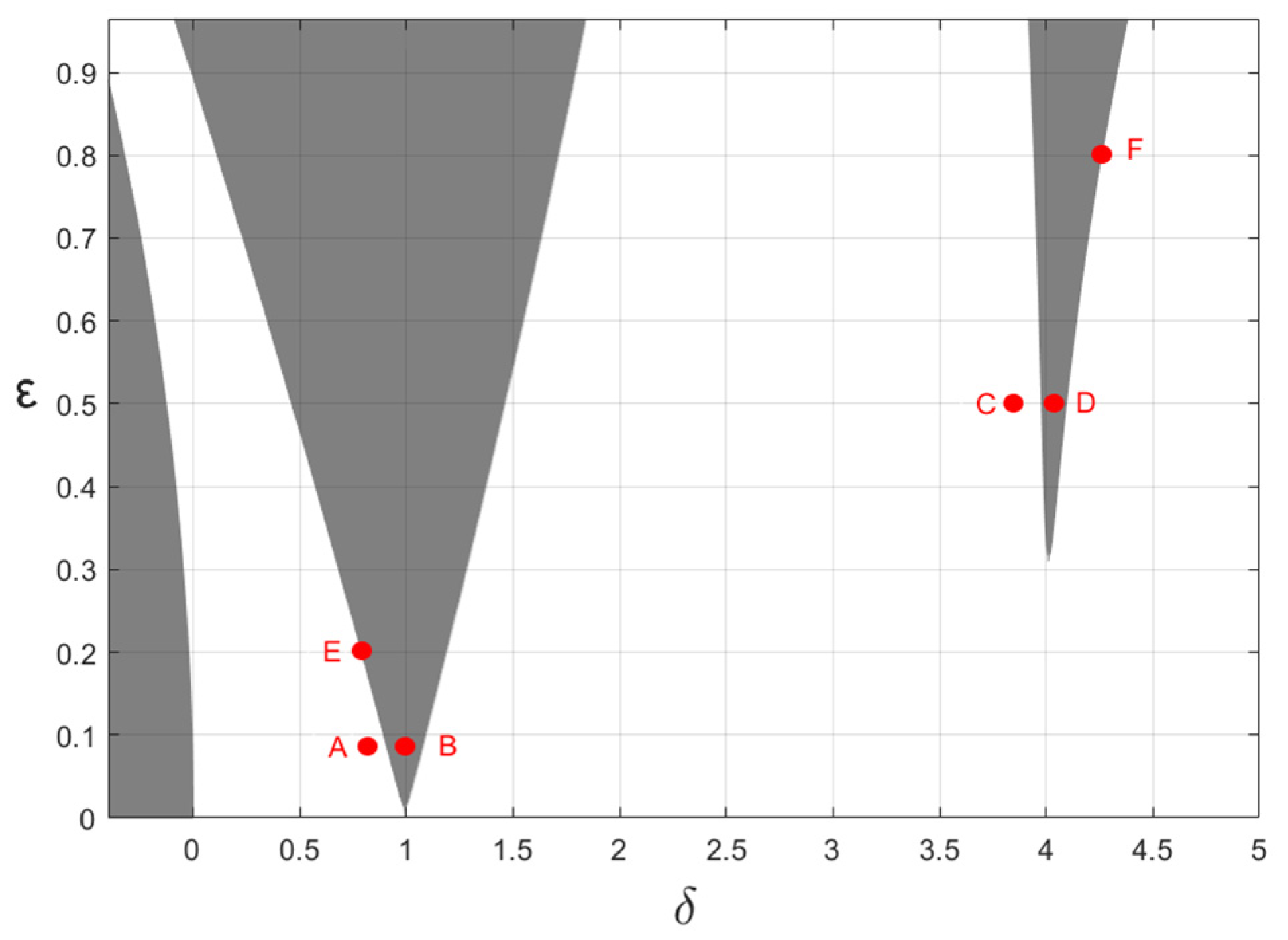
To verify the accuracy of the analytical results, we numerically tested the influence of forced excitation on the stability boundaries of Equation (4) by the numerical method. First, the stability boundaries were drawn according to Equations (34), (43), and (45), as shown in Figure 2. The three shaded parts in Figure 2 represent the unstable region near δ 0 = 0   ,   1 ,   4 respectively, and the blank region represents the stable region of the system. The boundaries of the intersection of the two regions are the stability boundaries of parametric excitation resonance.
When the system parameters change, the change of the stability boundaries near δ 0 = 1 and δ 0 = 4 are more obvious than the change near δ 0 = 0 , and the stability of the parameter points near the bottom of the stability boundaries is more sensitive and easy to change. Therefore, some typical points for numerical simulation were selected in the bottom area of the stability boundaries and near the boundary lines of δ 0 = 1 or δ 0 = 4 , The positions of these points are shown in Figure 2, and they are marked as points A, B, C, and D. In order to verify the relationship between the periodic solutions on the stability boundaries and the forced excitation, two points E and F on the boundary lines near δ 0 = 1 or δ 0 = 4 were selected to simulate randomly, as shown in Figure 2.
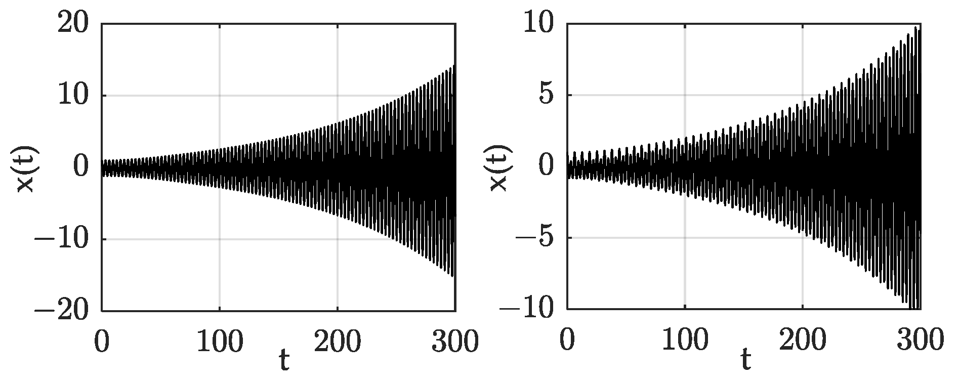
The responses of each typical point were compared and verified by the numerical method. The system parameters were selected as ξ = 0.005 , K = 0.005 , p = 0.5 , and w = 1 . Figure 3, Figure 4, Figure 5 and Figure 6 show the time–domain response of points A, B, C, and D respectively, in which sub-graph (a) is the response without forced excitation and sub-graph (b) is the response with forced excitation. It can be seen from the comparison diagrams in Figure 3, Figure 4, Figure 5 and Figure 6 that whether the point is in the stable region or the unstable region, the forced excitation did not change the stability of each point, but changed the speed of system convergence and divergence. This is consistent with the analytical results obtained in this paper, and the results confirmed the correctness of this paper’s conclusions.
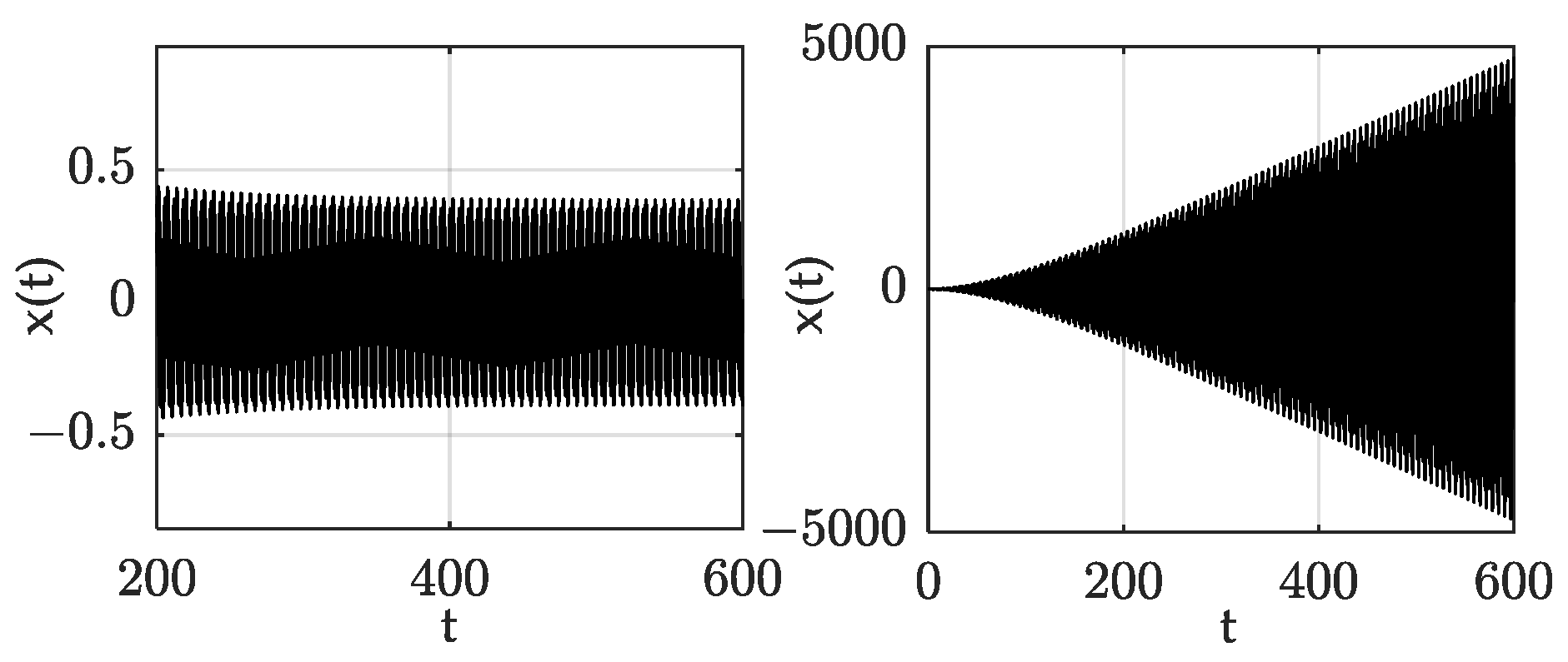
Figure 7 and Figure 8 are the time–domain response of points E and F respectively; sub-graph (a) is the response without forced excitation; and sub-graph (b) is the response with forced excitation with a frequency equal to the frequency of the corresponding periodic solutions. By comparison, it was found that when there was no forced excitation, the system responses corresponding to the E and F parameter points were periodic, but became divergent when the forced excitation was loaded. This phenomenon proved that when the forced excitation frequency was close to the periodic solutions frequency of the stability boundaries, those points on the stability boundaries became unstable. This result is consistent with the conclusion that the forced excitation frequency did not meet the definition domain in the analytical deduced process.

3.2. Effects of Damping and Fractional-Order Parameters on the Stability Boundaries

In this section, the effect of system parameters on stability boundaries is analyzed. The basic parameters were selected as K = 0.005 , p = 0.5 , and F = 0 ; ξ was selected as 0, 0.03, and 0.05, respectively The stability boundaries are shown in Figure 9. It can be seen that the increase in the damping ξ made the stability boundaries move upward and the range of the stable region expanded gradually.
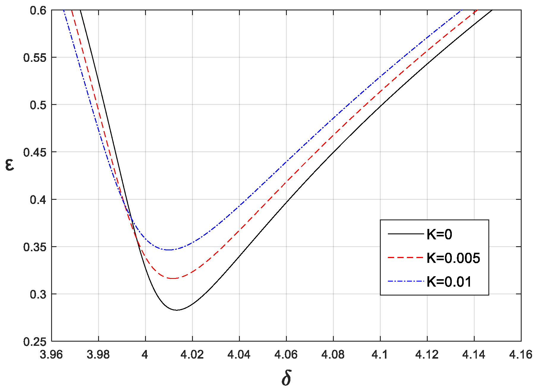
When the damping and the order of the fractional-order derivative were selected as ξ = 0.005, p = 0.5 and the coefficients of the fractional-order derivative K were selected as 0, 0.005, and 0.01, respectively, the stability boundaries near δ 0 = 4 were as shown in Figure 10. As the coefficient K increased, the stability boundaries moved to the left and gradually moved upward. The main reason for this phenomenon was that the equivalent stiffness and the equivalent damping of the fractional-order derivative were both gradually increasing. In addition, when the fractional-order differential coefficient K was selected as 0.005 and the fractional-order differential order p was selected as 0, 0.5, and 0.8, respectively. The stability boundaries were as shown in Figure 11. It can also be seen that with the increase in p, due to the equivalent stiffness decreasing and the equivalent damping increasing, the stability boundaries moved upward and the position obviously shifted to the right. In short, we found that the fractional-order derivative not only affects the position of the stability boundaries but also changes the range of the stability region.

4. Stability Analysis of Periodic Solutions

4.1. Periodic Solutions in the Mathieu Equation

The Mathieu equation is a special case of Hill’s equation, and Hill’s equation can be expressed as
x ¨ + [ α + β f ( t ) ] x = 0 ,
where α and β are two independent parameters, α is the natural frequency of the system, β is the parametric excitation coefficient, f ( t ) = f ( t + T ) , and T is the least period of f ( t ) .
According to the Floquet theory, the k’T-periodic solutions of Equation (47) can be obtained when λ k = 1 . To find the value of λ for the k’T-periodic solutions, we used its polar form, i.e.:
x ( t + k T ) = λ k x ( t ) = r k e j k θ x ( t ) .
According to r k = 1 ,   e j k θ = cos ( k θ ) + j sin ( k θ ) = 1 , the angle conditions for k’T-periodic solutions is as follows:
θ = ± 2 π k .
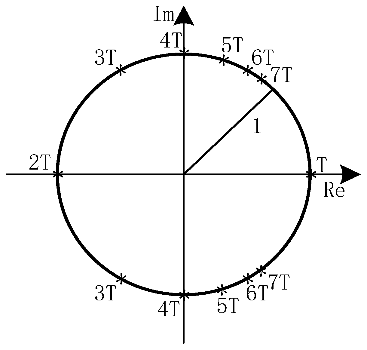
From the angle conditions [24], we determined that the unit circle shows the eigenvalues’ positions of k’T-periodic solutions, as shown in Figure 12.
Consequently, the eigenvalues λ corresponding to any k’ can be obtained:
k = 1 , θ = 2 π   λ 1 , 2 = { 1 , 1 } k = 2 , θ = π   λ 1 , 2 = { 1 , 1 } k = 3 , θ = 2 π 3   λ 1 , 2 = { 1 2 + j 3 2 , 1 2 j 3 2 } k = 4 , θ = π 2   λ 1 , 2 = { j , j }
From the unit circle diagram, the corresponding eigenvalues of different periods can be clearly defined. Therefore, when the value of ( δ , ε ) is fixed and the Floquet multiplier satisfies Equation (49), the k’T-periodic solution can be obtained. As k’ is increased, the angle condition θ gradually approached zero, and the k’T-periodic solutions were gradually closer to T-periodic solutions, thus affecting the stability of the stability boundary.
Next, we considered the homogeneous Mathieu equation:
x ¨ + ( δ + 2 ε cos ( 2 t ) ) x = 0 .
In Equation (51), the least period T = π , and the f ( t ) = cos 2 t satisfies the following equation:
0 T f ( t ) d t = 0 .
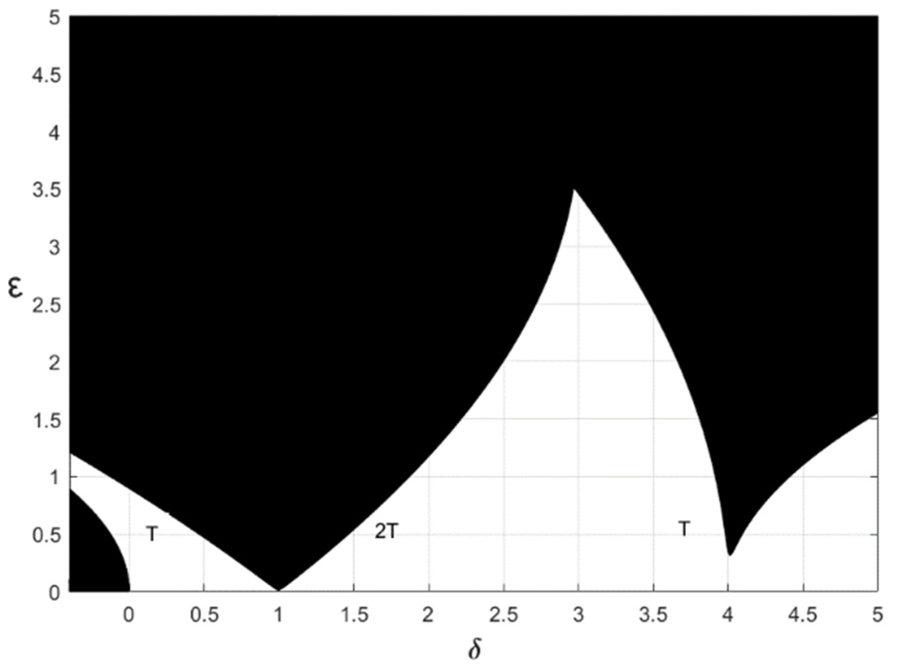
The stability-chart of Equation (51) is shown in Figure 13. There, exit π -period solutions or 2 π -period solutions are shown on the stability boundaries. In addition, there were stable periodic solutions of k’ π -period distributed in the stable region (i.e., the blank region).
Then, we analyzed the non-homogeneous Mathieu equation, as follows:
x ¨ + ( δ + 2 ε cos ( 2 t ) ) x = i = 1 r F cos ( w i t ) ,
where the angular frequency of the forced excitation is wi, and the least period of the forced excitation satisfies T i = 2 π / w i .
When there was no forced excitation, the k’T-periodic solutions remained stable in the stable region. However, when the forced excitation was loaded and the least period of the forced excitation was the same as the least period of the k’T-periodic solutions, those parameter points corresponding to the k’T-periodic solutions in δ - ε plane became divergent. Meanwhile, the angular frequency and the coefficient k’ satisfies k = 2 / w i .

4.2. Numerical Simulation

In this section, the stability of k’T-periodic solutions is analyzed through numerical simulation to verify the correctness of the theoretical research.
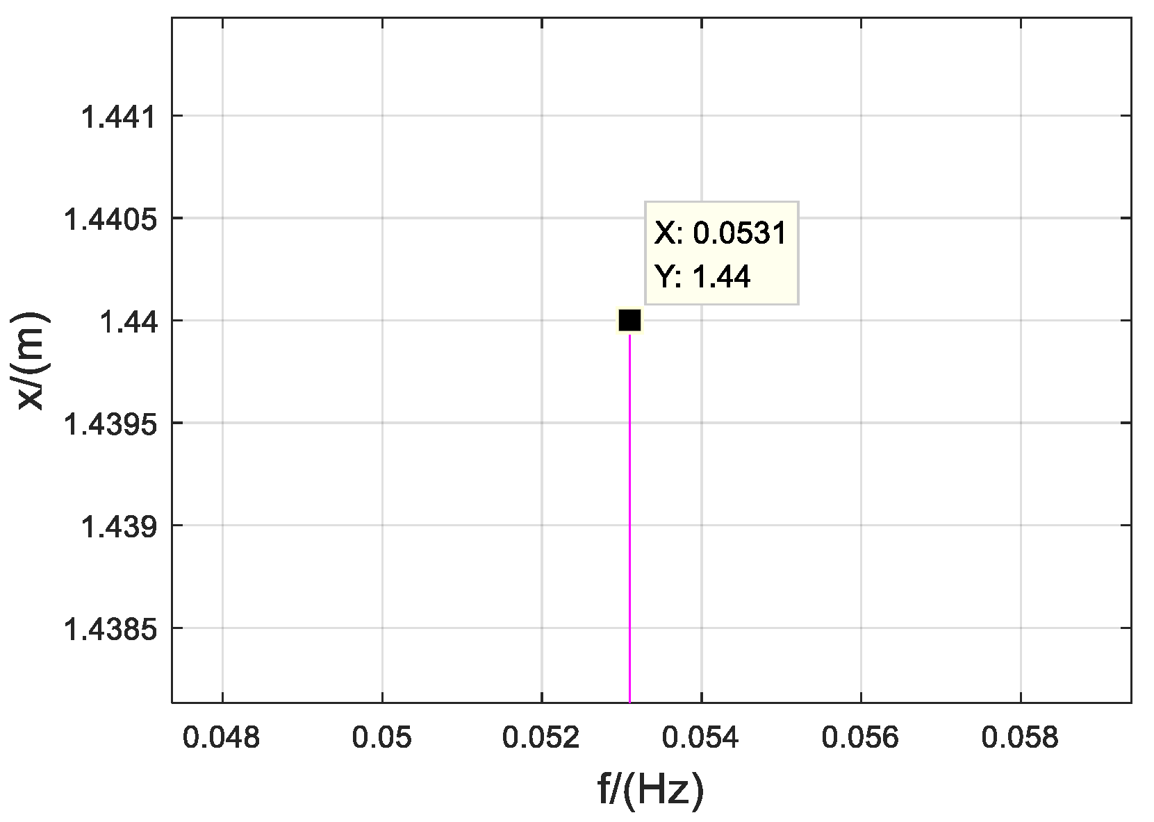
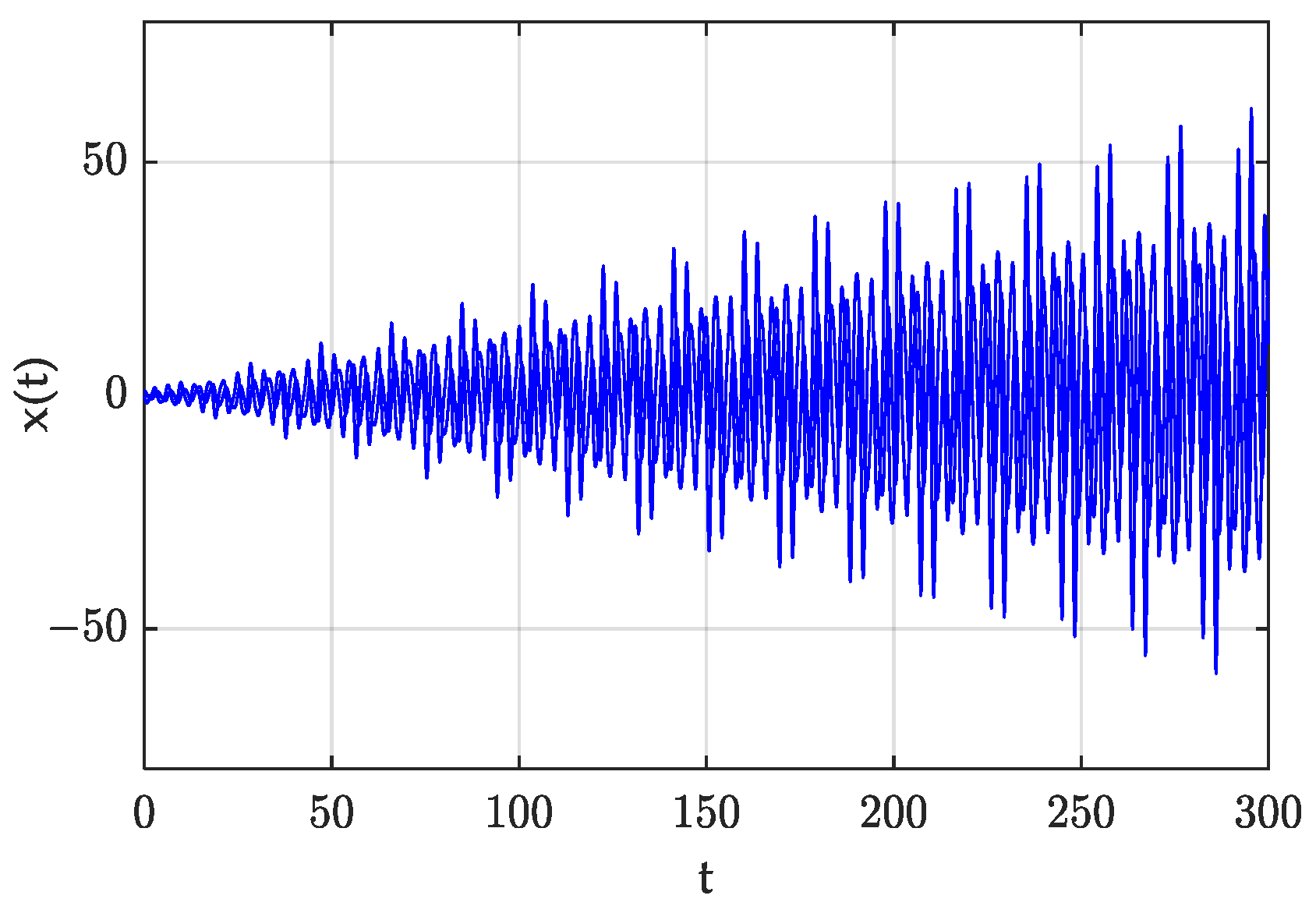
When δ = 3 , ε = 1 , the system response of the Mathieu equation without the forced excitation is as shown in Figure 14. It is a steady periodic motion. The spectrum diagram of this response is shown in Figure 15. We found that the frequency of this periodic motion was 0.053 Hz, meaning the angular frequency was 6 π . We selected w i = 1 / 3 , and this tim, the forced excitation frequency was 6 π . The response of the non-homogeneous Mathieu equation is shown in Figure 16. It became divergent. From the results of these three figures, it was obvious that when the points with k’T-periodic solutions in the stable region were affected by the same frequency of forced excitation, their stability changed from stable to divergent, due to resonance.
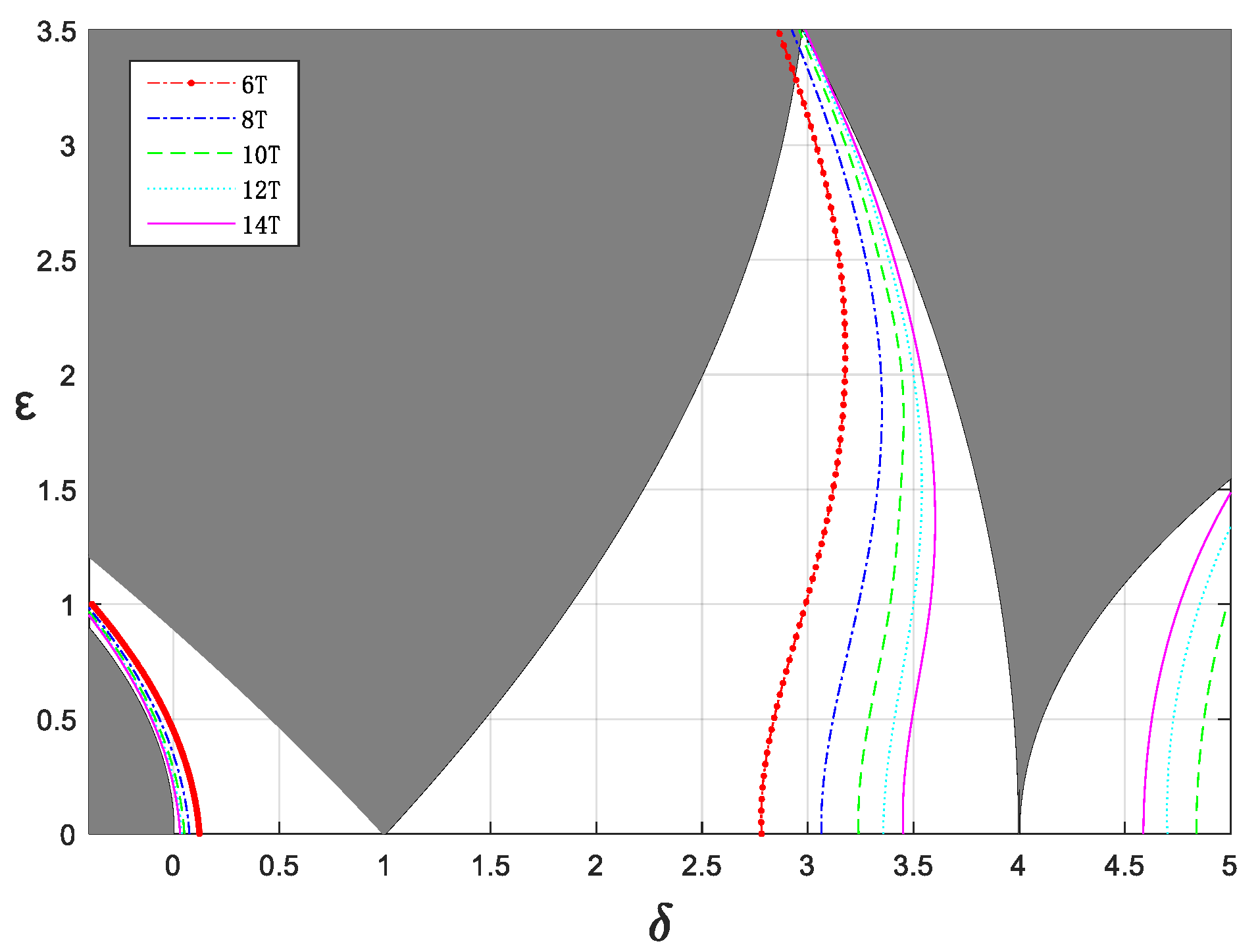
To analyze the distribution law of such unstable points more carefully, five kinds of forced excitation with different angular frequencies ( w i = 1 / n   ,   n = ( 3 , 4 7 ) ) were selected. The simulated results are shown in Figure 17. As can be seen from the figure, a large number of unstable points appeared in the stable region, due to the influence of forced excitation, and these points formed multiple linear regions with extremely thin widths (hereinafter referred to as the resonance line). The positions of these resonance lines were affected by forced-excitation frequency, but these resonance lines had a similar trend. In addition, we found that as the value of n increased, the position of the k’T-resonance lines gradually approached the stability boundaries. These results were consistent with the theoretical results in Section 4.1.

4.3. Effects of Damping and Fractional-Order Parameters on Resonance Lines

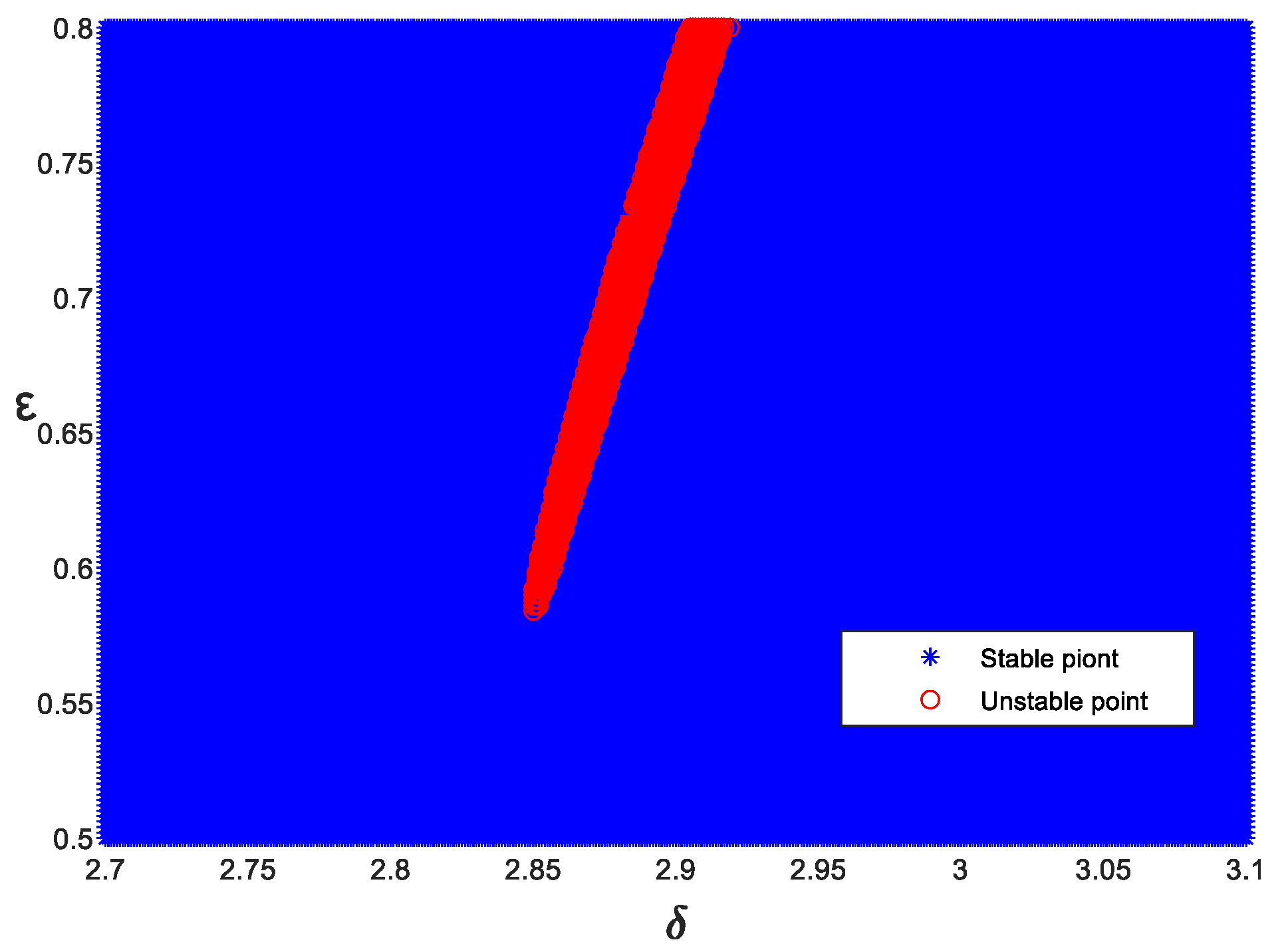
To analyze more intuitively the influence of the system parameters on the resonance line in Equation (4), we selected the parameter points of the 6T-resonance line in δ = 2.7~3.1 and ε = 0.5~0.8 for local amplification analysis. The system parameters were selected as K= 0.075, p = 0.5, ξ = 0 , wi = 1/3, and F = 1; the step size of ε was 0.002, and the step size of δ was 0.001. The local chart of the 6T-resonance line of the Mathieu equation with forced excitation is shown in Figure 18. The red points represent unstable points, and the blue points represent stable points. It can be seen that the resonance line was in the shape of a long strip in the case of local magnification, and its width gradually increased as the value ε became larger.
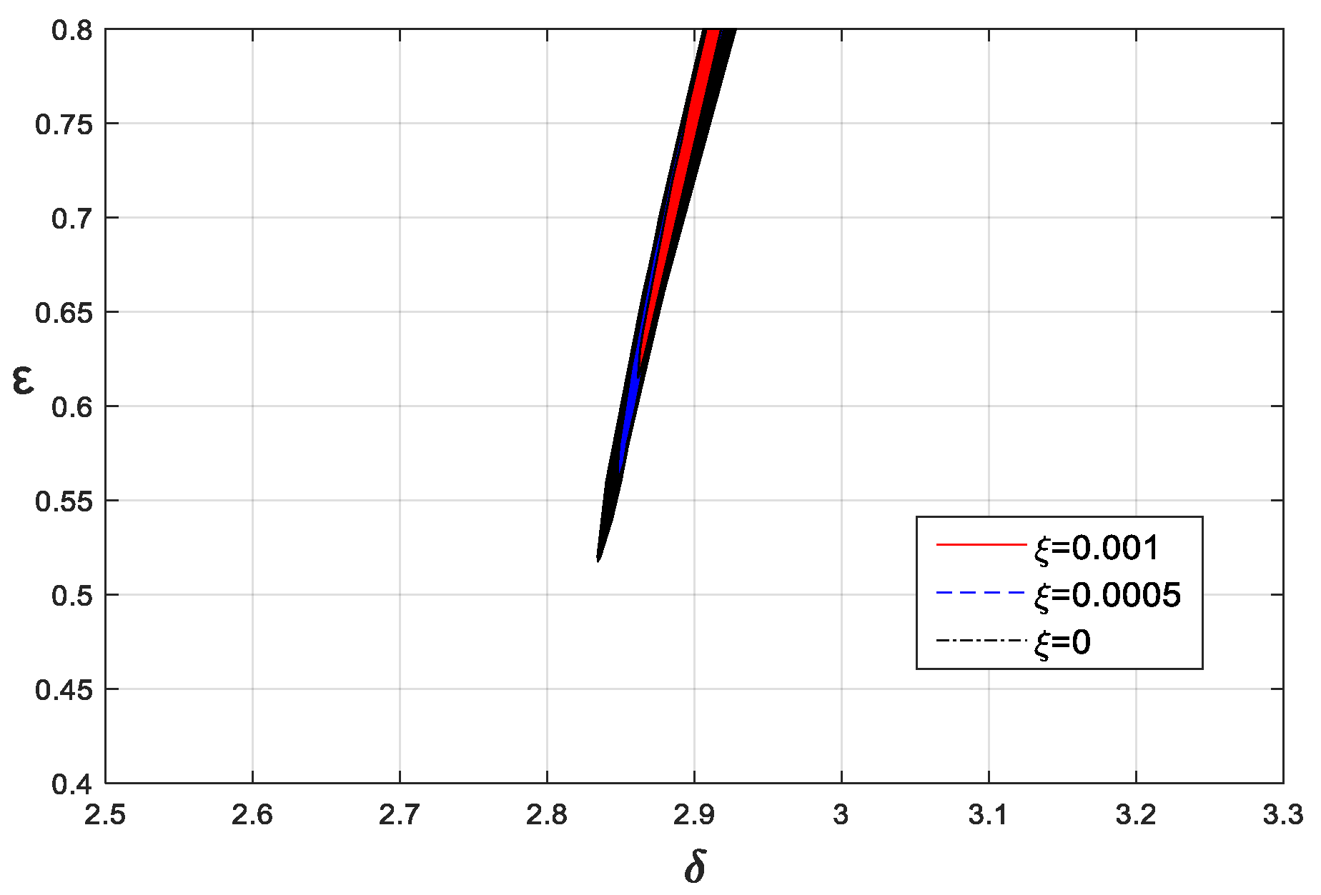
Next, the effects of linear damping and fractional-order parameters on resonance lines were analyzed. The basic parameters of Equation (4) were selected as F = 1, wi = 1, K = 0.005, and p = 0.5, and the linear damping was selected as 0, 0.001, and 0.005, respectively. The 6T-resonance line is shown in Figure 19. As can be seen from Figure 19, the resonance line gradually shrank upward and narrowed in width as the damping increased. Therefore, the damping changed the position of the resonance line, and the increase in damping not only reduced the influence of forced excitation, but also enlarged the range of the system stability region.
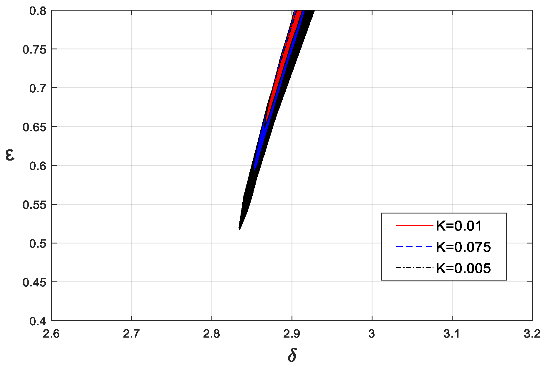
The effects of fractional parameters on resonance lines are discussed below. The basic parameters of Equation (4) were selected as ξ = 0 , F = 1, wi = 1/3, and p = 0.5, and K was 0.01, 0.075, and 0.005, respectively. The 6T-resonance lines are shown in Figure 20. It can be seen that the change in the fractional-order derivative coefficient K changed the position and range of the resonance line. When K increased gradually, the position of the resonance line shifted to the left, due to the increase in the equivalent stiffness of the system caused by the fractional-order derivative term. In addition, the resonance line moved upwards and became narrower, due to the gradual increase in the equivalent damping.
When K was 0.005 and p was 0, 0.5, and 1, the 6T-resonance lines were as shown in Figure 21. It also can be seen that as p increased, the resonance line gradually moved to the right. This was because the equivalent stiffness of the system decreased gradually, due to the fractional-derivative term. In addition, as p increased, the equivalent linear damping gradually increased, and the resonance line gradually moved upward. In sum, both the damping and the fractional-order parameters had important effects on the position and range of the resonance line, caused by forced excitation.

5. Conclusions

On the basis of the model of the pantograph–catenary system, the stability analysis of the non-homogeneous fractional-order Mathieu equation was concluded by the perturbation method and numerical simulation. We proved that forced excitation with a finite period does not change the convergence of the stability boundary. Only when the period of the forced excitation is large enough will the stability boundary become unstable. We verified that k’T-periodic solutions in the stable region of the non-homogeneous Mathieu equation are unstable under the influence of forced excitation. When the frequency of forced excitation is close to the frequency of the k’T-periodic solutions, unstable resonance lines appear in the stable region. Finally, by analyzing the influence of system parameters on the resonance line, we found that both the damping and fractional-order derivative term in the system affect the position and range of the resonance line region. These results reveal the complex dynamic behavior of fractional-order parametric excitation systems under the influence of forced excitation, information that can be used to guide system design and optimization.
In addition, based on this paper’s research results, the following extensions can be attempted: (1) Due to the complexity of the external influence of the vehicle, the pantograph–catenary system with random excitation will be carried out; (2) The stability changes will be further investigated under the influence of the dropper spacing in the pantograph–catenary system; and (3) The study of the periodic and chaotic dynamical behavior of the pantograph-–catenary system will be further explored.

Author Contributions

Conceptualization, R.M. and S.W.; methodology, S.W.; software, R.M.; validation, R.M., S.W. and Y.S.; formal analysis, R.M.; investigation, R.M. and C.S.; resources, R.M.; data curation, R.M.; writing—original draft preparation, R.M.; writing—review and editing, S.W. and Y.S.; visualization, C.S.; supervision, Y.S.; project administration, S.W.; funding acquisition, S.W. All authors have read and agreed to the published version of the manuscript.

Funding

This research was funded by the National Natural Science Foundation of China (12072206, U1934201, 11972237) and the education department project of Hebei Province (ZD2020310).

Data Availability Statement

Not applicable.

Conflicts of Interest

The authors declare no conflict of interest.

References

  1. Petras, I. Fractional-Order Nonlinear Systems: Modeling, Analysis and Simulation; Higher Education Press: Beijing, China, 2011; pp. 18–19. [Google Scholar]
  2. Podlubny, I. Fractional-Order Differential Equations; Academic Press: New York, NY, USA, 1999. [Google Scholar]
  3. Kilbas, A.; Srivastava, H.; Trujillo, J. Theory and Applications of Fractional-Order Differential Equations; Elsevier Science Limited: Amsterdam, The Netherlands, 2006. [Google Scholar]
  4. Ziada, E. Analytical Solution of Nonlinear System of Fractional Differential Equations. J. Appl. Math. Phys. 2021, 9, 2544–2557. [Google Scholar] [CrossRef]
  5. Mu’lla, M. Fractional Calculus, Fractional Differential Equations and Applications. Open Access Libr. J. 2020, 7, 1–9. [Google Scholar] [CrossRef]
  6. Wang, Q.; Xu, R. New Development on Fractional Order Calculus Operators. J. Binzhou Univ. 2021, 37, 51–58. [Google Scholar]
  7. Li, X.; Wang, Z. Modeling of Discrete Fracmemristor and Its Application in Logistic Mapping. Electron. Compon. Mater. 2022, 41, 627–634. [Google Scholar]
  8. Yang, J. Stabilization of Fractional Multiparameter Control Systems based on Cylindrical Algebraic Division Method. In Proceedings of the 33rd China Conference on Control and Decision-Making, Kunming, China, 22–24 May 2021; Volume 11, pp. 315–320. [Google Scholar] [CrossRef]
  9. Tang, J.; Li, X.; Wang, M. Dynamic Response and Vibration Isolation Effect of Generalized Fractional-Order Van Der Pol-Duffing Oscillator. Vib. Shock. 2022, 9, 10–18. [Google Scholar]
  10. He, X.; Hu, Z. Research on Optimal Design of Fractional Order Lowpass Filters. Acta Electron. Sin. 2022, 50, 185–194. [Google Scholar]
  11. Shen, Y.; Li, H.; Yang, S. Primary and Subharmonic Simultaneous Resonance of Duffing Oscillator. Nonlinear Dyn. 2020, 102, 1485–1497. [Google Scholar] [CrossRef]
  12. Qi, Z.; Wang, X.; Mo, R. Air Spring Modeling and Vehicle Dynamics Analysis Based on Fractional Calculus Theory. J. China Railw. Soc. 2021, 43, 67–76. [Google Scholar]
  13. Lu, Y.; Wang, C.; Deng, Q. The Dynamics of a Memristor-based Rulkov Neuron with Fractional-Order Difference. Chin. Phys. B 2022, 31, 46–54. [Google Scholar] [CrossRef]
  14. Chen, L.; Yin, H.; Huang, T. Chaos in Fractional-Order Discrete Neural Networks with Application to Image Encryption. Neural Netw. 2020, 125, 174–184. [Google Scholar] [CrossRef]
  15. Hou, J.; Yang, S.; Li, Q. Effects of Speed Feedback Fractional Order PID Control on Vibration Characteristics of Gear System. J. Vib. Shock. 2021, 40, 175–181. [Google Scholar]
  16. Chang, Y.; Tian, W.; Jin, G. Research on Nonlinear Fractional Active Control Suspension Based on Fractional Order PIλDμ. J. Yanshan Univ. 2020, 44, 575–580. [Google Scholar]
  17. Wang, L.; Cui, L.; Han, Z.; Ying, W. Parametric Excited Vibration Control of a SMA Beam under Fluctuating Temperature. J. Vib. Shock. 2022, 41, 135–138. [Google Scholar]
  18. Xu, M.; Li, L.; Ren, S. Numerical Method for Stability Analysis of Multiple-Degree-of-Freedom Parametric Dynamic Systems. Chin. J. Comput. Mech. 2020, 37, 48–52. [Google Scholar]
  19. Tang, Y.; Wang, L.; Liu, Z. Ship Nonlinear Dynamics Analysis Method and Its Engineering Applications. Ship Boat 2022, 33, 1–14. [Google Scholar]
  20. Zhu, D.; Xue, R.; Cao, X. Vehicle Random Vibration Analysis Using a SDOF Parametric Excitation Model. J. Vib. Shock. 2022, 41, 79–86. [Google Scholar]
  21. Li, G.; Zhu, Z.; Cheng, C. Dynamical Stability of Viscoelastic Column with Fractional Derivative Constitutive Relation. Appl. Math. Mech. 2001, 22, 294–303. [Google Scholar] [CrossRef]
  22. Wen, S. Dynamics and Control of Fractional-Order Parametrically Excited System. PhD. Dissertation, Shijiazhuang Tiedao University, Shijiazhuang, China, 2018; pp. 22–37. [Google Scholar]
  23. Guo, J.; Shen, Y.; Li, H. Dynamic Analysis of Quasi-periodic Mathieu Equation with Fractional-Order Derivative. Chin. J. Theor. Appl. Mech. Sin. 2021, 53, 3366–3375. [Google Scholar]
  24. Rodriguez, A.; Collado, J. Periodic Solutions in Non-Homogeneous Hill Equation. Nonlinear Dyn. Syst. Theory 2020, 20, 78–91. [Google Scholar]
  25. Yang, S.; Liu, Y. Development of Rail Vehicle Dynamics and Control. J. Dyn. Control. 2020, 18, 1–4. [Google Scholar]
  26. Tian, Q.; Zhang, B. Research on Application and Development Trend of Air Spring in Railway Vehicle. New Ind. 2021, 11, 173–174. [Google Scholar]
  27. Yakubovich, V.; Starzhinski, V. Linear Differential Equations with Periodic Coeffi-Cients; Wiley: New York, NY, USA, 1975. [Google Scholar]
  28. Slane, J.; Tragessser, S. Analysis of Periodic Nonautonomous Inhomogeneous Systems. Nonlinear Dyn. Syst. Theory 2011, 11, 183–198. [Google Scholar]
  29. Diethelm, K. The Analysis of Fractional-Order Differential Equations: An Application-Oriented Exposition Using Differential Operators of Caputo Type; Springer: New York, NY, USA, 2010. [Google Scholar]
  30. Abu-Shady, M.; Kaabar, M.K.A. A Generalized Definition of the Fractional Derivative with Applications. Math. Probl. Eng. 2021, 9, 9444803. [Google Scholar] [CrossRef]
  31. Abu-Shady, M.; Kaabar, M.K.A. A Novel Computational Tool for The Fractional-Order Special Functions Arising from Modeling Scientific Phenomena via Abu-Shady–Kaabar Fractional Derivative. Comput. Math. Methods Med. 2022, 5, 2138775. [Google Scholar] [CrossRef] [PubMed]
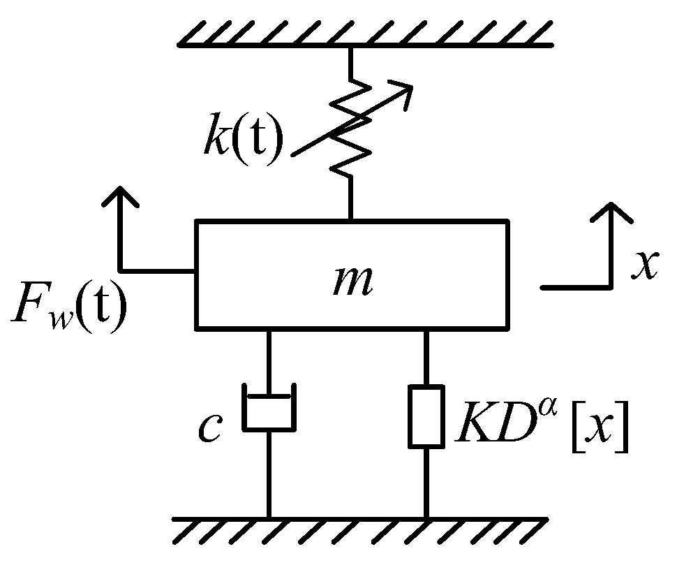
Figure 1. The fractional-order model of the pantograph–catenary system.
Fractalfract 06 00633 g001
Figure 2. Stability chart of system (4), marked with the positions of randomly selected points A–F.
Fractalfract 06 00633 g002
Figure 3. Response of point A, with F=0 (left) and F=1 (right).
Fractalfract 06 00633 g003
Figure 4. Response of point B, with F=0 (left) and F=1 (right).
Fractalfract 06 00633 g004
Figure 5. Response of point C, with F=0 (left) and F=1 (right).
Fractalfract 06 00633 g005
Figure 6. Response of point D, with F=0 (left) and F=1 (right).
Fractalfract 06 00633 g006
Figure 7. Response of point E, with F=0 (left) and F=1 (right).
Fractalfract 06 00633 g007
Figure 8. Response of point F, with F = 0 (left) and F = 1 (right).
Fractalfract 06 00633 g008
Figure 9. Stability chart of Mathieu equation: x ¨ + 2 ξ x ˙ + ( δ + 2 ε cos 2 t ) x + K D P [ x ] = 0 .
Fractalfract 06 00633 g009
Figure 10. The effects of K on stability boundaries ( δ 0 = 4 ).
Fractalfract 06 00633 g010
Figure 11. The effects of p on stability boundaries ( δ 0 = 4 ).
Fractalfract 06 00633 g011
Figure 12. The unit circle shows the eigenvalues’ positions of k’T-periodic solutions.
Fractalfract 06 00633 g012
Figure 13. Stability chart of x ¨ + ( δ + 2 ε cos ( 2 t ) ) x = 0 .
Fractalfract 06 00633 g013
Figure 14. System response of x ¨ + ( δ + 2 ε cos 2 t ) x = 0 with ( δ = 3 , ε = 1 ).
Fractalfract 06 00633 g014
Figure 15. Spectrum diagram.
Fractalfract 06 00633 g015
Figure 16. System response of x ¨ + ( δ + 2 ε cos 2 t ) x = F cos ( t / 3 ) with ( δ = 3 , ε = 1 ).
Fractalfract 06 00633 g016
Figure 17. Stability chart of: x ¨ + ( δ + 2 ε cos 2 t ) x = n = 3 7 F cos ( t / n ) .
Fractalfract 06 00633 g017
Figure 18. Local chart of the 6T-resonance line: x ¨ + 2 ξ x ˙ + ( δ + 2 ε cos 2 t ) x + K D P [ x ] = F cos ( t / 3 ) .
Fractalfract 06 00633 g018
Figure 19. The effects of ξ on the 6T-resonance line.
Fractalfract 06 00633 g019
Figure 20. The effects of K on the 6T-resonance line.
Fractalfract 06 00633 g020
Figure 21. The effects of p on the 6T-resonance line.
Fractalfract 06 00633 g021
Publisher’s Note: MDPI stays neutral with regard to jurisdictional claims in published maps and institutional affiliations.