

Fractional-Order LCL Filters: Principle, Frequency Characteristics, and Their Analysis


Abstract
1. Introduction
- (1)
- This paper pioneered a method for the theoretical analysis of the frequency characteristics of fractional-order LCL filters, summarized their five critical properties, and systematically revealed their principles and frequency characteristics.
- (2)
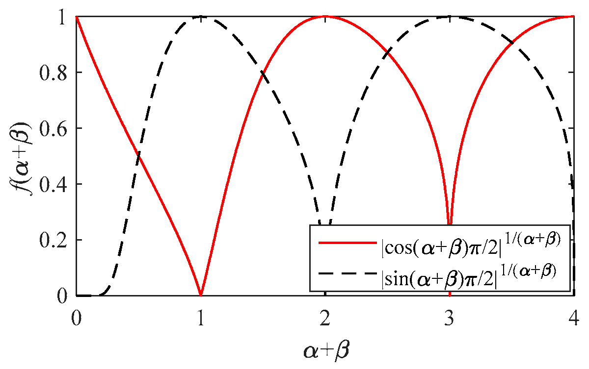
- It is found that the necessary and sufficient condition for resonance in the magnitude-frequency characteristic curve of fractional-order LCL filters is that the sum of the orders of the fractional-order inductor and the fractional-order capacitor is equal to 2. This provides a theoretical basis for effectively avoiding resonance in fractional-order LCL filters.
- (3)
- This paper fills the gap in the research on the frequency characteristics of general fractional systems with -order (where ).
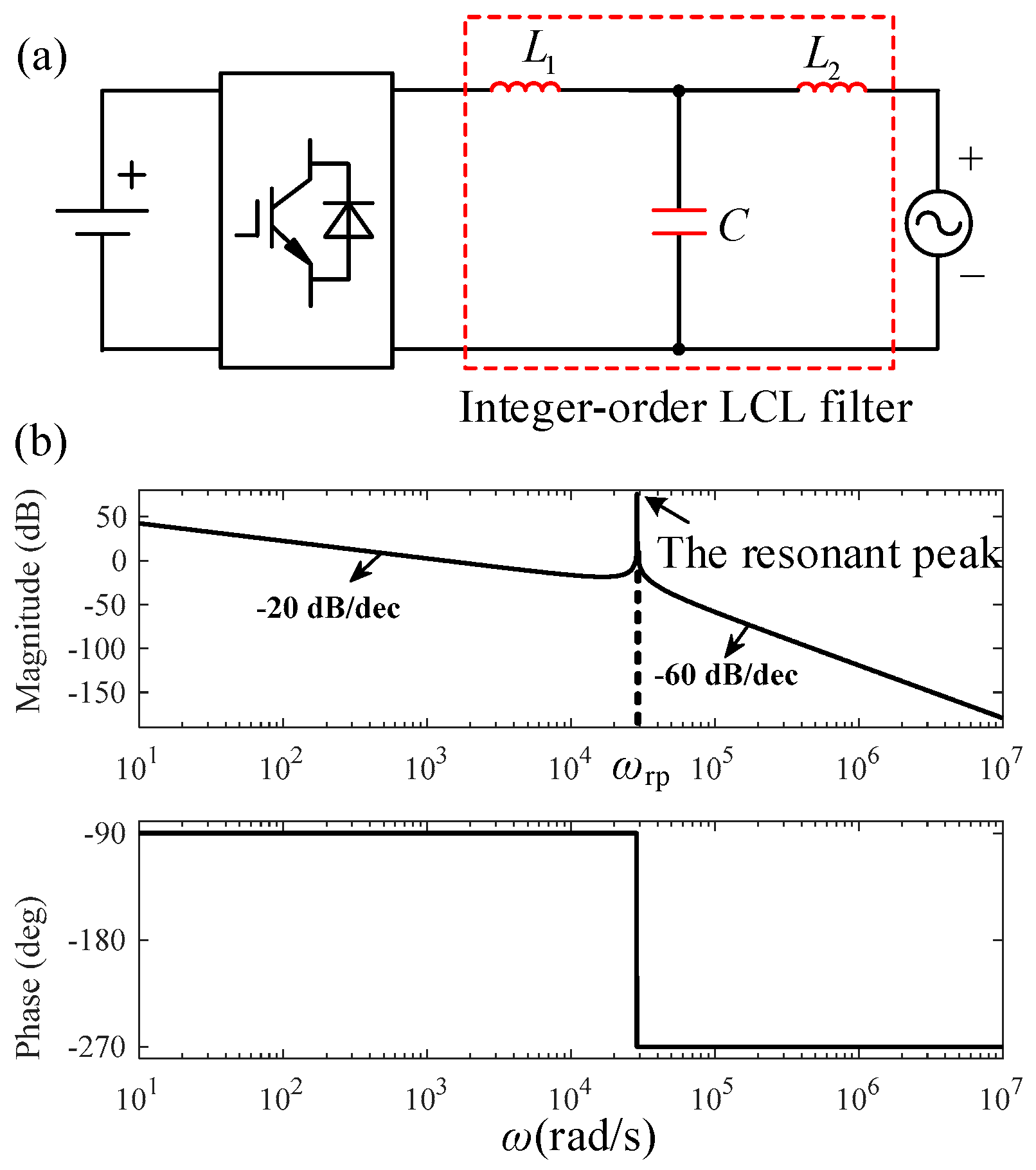
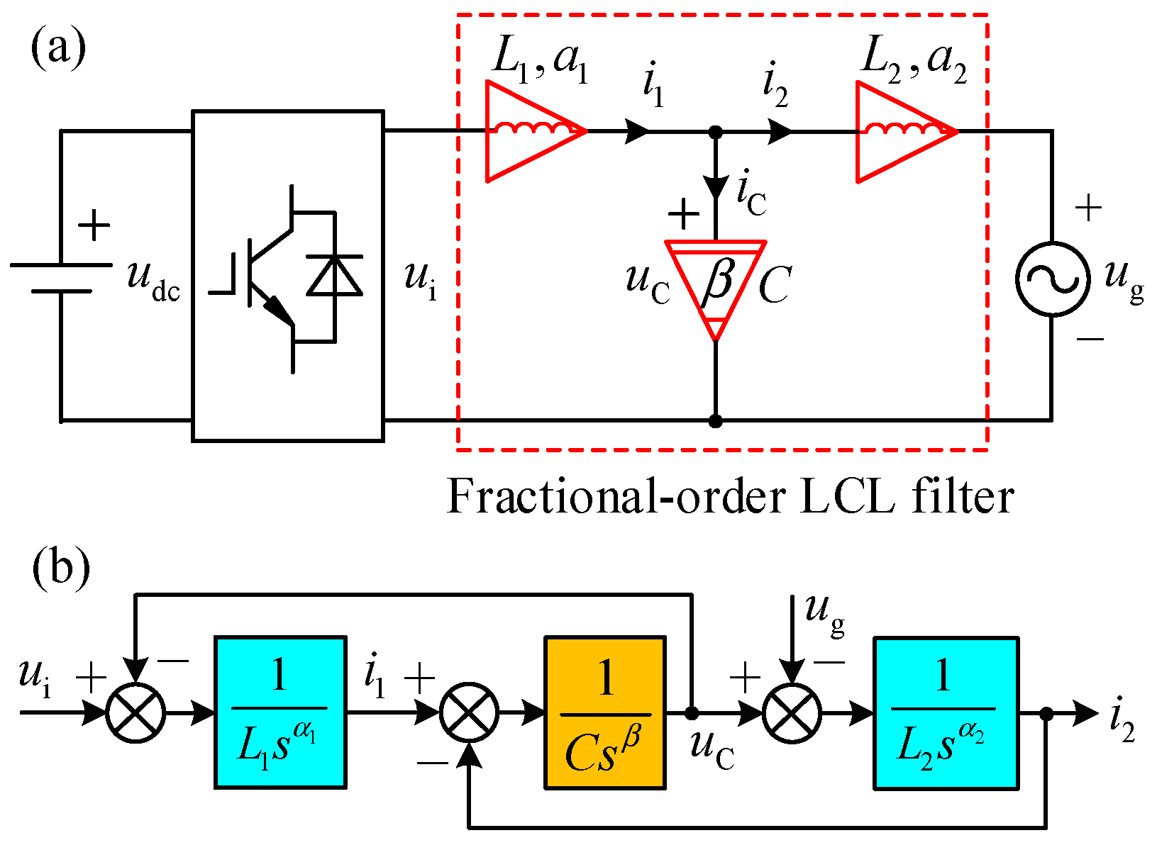
2. The Circuit and Mathematical Models of a Fractional-Order LCL Filter
3. The Frequency Characteristics and Analysis of a Fractional-Order LCL Filter
3.1. The Resonance Characteristics of a Fractional-Order LCL Filter
3.2. The Corner Frequency and Logarithmic Magnitude-Frequency Characteristics of a Fractional-Order LCL Filter
3.3. The Phase-Frequency Characteristics of a Fractional-Order LCL Filter
3.4. The Phase Crossover Frequency and Gain Margin of a Fractional-Order LCL Filter
3.5. The Gain Crossover Frequency and Phase Margin of a Fractional-Order LCL Filter
4. Simulation Results and Analysis
4.1. The Frequency Characteristic Simulation Curves of a Fractional-Order LCL Filter
4.2. The Analysis of the Frequency Characteristics of a Fractional-Order LCL Filter
5. Conclusions
Author Contributions
Funding
Data Availability Statement
Conflicts of Interest
References
- Podlubny, I. Fractional Differential Equations; Academic: New York, NY, USA, 1999. [Google Scholar]
- Monje, C.A.; Chen, Y.; Vinagre, B.M.; Xue, D.; Feliu, V. Fractional-Order Systems and Controls: Fundamentals and Applications; Springer: London, UK, 2010. [Google Scholar]
- Petras, I. Fractional Calculus. In Fractional-Order Nonlinear Systems; Higher Education: Beijing, China, 2011. [Google Scholar]
- Radwan, A.G.; Soliman, A.M.; Elwakil, A.S. Design equations for fractional-order sinusoidal oscillators: Four practical circuit examples. Int. J. Circuit Theory Appl. 2008, 36, 473–492. [Google Scholar] [CrossRef]
- Elwakil, A.S. Fractional-order circuits and systems: An emerging interdisciplinary research area. IEEE Circuits Syst. Mag. 2010, 10, 40–50. [Google Scholar] [CrossRef]
- Radwan, A.G.; Salama, K.N. Fractional-order RC and RL circuits. Circuits Syst. Signal Process. 2012, 31, 1901–1915. [Google Scholar] [CrossRef]
- Radwan, A.G.; Fouda, M.E. Optimization of Fractional-Order RLC Filters. Circuits Syst. Signal Process. 2013, 32, 2097–2118. [Google Scholar] [CrossRef]
- Xu, J.; Li, X.; Meng, X.; Qin, J.; Liu, H. Modeling and analysis of a single-phase fractional-order voltage source pulse width modulation rectifier. J. Power Sources 2020, 479, 228821. [Google Scholar] [CrossRef]
- Xu, J.; Li, X.; Liu, H.; Meng, X. Fractional-order modeling and analysis of a Three-phase Voltage Source PWM Rectifier. IEEE Access 2020, 8, 13507–13515. [Google Scholar] [CrossRef]
- Freeborn, T.J.; Maundy, B.; Elwakil, A. Fractional resonance-based RLβCα filters. Math. Probl. Eng. 2013, 2013, 726721. [Google Scholar] [CrossRef]
- Diao, L.; Zhang, X.; Chen, D. Fractional-order multiple RL alpha C beta circuit. Acta Phys. Sin. 2014, 63, 038401. [Google Scholar] [CrossRef]
- Westerlund, S.; Ekstam, L. Capacitor theory. IEEE Trans. Dielectr. Elect. Insul. 1994, 1, 826–839. [Google Scholar] [CrossRef]
- Westerlund, S. Dead Matter Has Memory; Causal Consulting: Kalmar, Sweden, 2002. [Google Scholar]
- Valsa, J.; Vlach, J. RC models of a constant phase element. Int. J. Circuit Theory Appl. 2013, 41, 59–67. [Google Scholar] [CrossRef]
- Sarafraz, M.S.; Tavazoei, M.S. Passive realization of fractional-order impedances by a fractional element and RLC components: Conditions and procedure. IEEE Trans. Circuits Syst. I Reg. Pap. 2017, 64, 585–595. [Google Scholar] [CrossRef]
- Semary, M.S.; Fouda, M.E.; Hassan, H.N.; Radwan, A.G. Realization of fractional-order capacitor based on passive symmetric network. J. Adv. Res. 2019, 18, 147–159. [Google Scholar] [CrossRef]
- Tsirimokou, G.; Psychalinos, C.; Elwakil, A.S. Emulation of a constant phase element using operational transconductance amplifiers. Analog Integr. Circuits Signal Process. 2015, 85, 413–423. [Google Scholar] [CrossRef]
- Bertsias, P.; Psychalinos, C.; Radwan, A.G.; Elwakil, A.S. High-Frequency Capacitorless Fractional-Order CPE and FI Emulator. Circuits Syst. Signal Process. 2018, 37, 2694–2713. [Google Scholar] [CrossRef]
- Jiang, Y.; Zhang, B. High-Power Fractional-Order Capacitor With 1 < alpha < 2 Based on Power Converter. IEEE Trans. Ind. Electron. 2018, 65, 3157–3164. [Google Scholar]
- Kapoulea, S.; Psychalinos, C.; Elwakil, A.S.; Radwan, A.G. One-terminal electronically controlled fractional-order capacitor and inductor emulator. AEU-Int. J. Electron. Commun. 2019, 103, 32–45. [Google Scholar] [CrossRef]
- Jesus, I.S.; Machado, J.A.T. Development of fractional order capacitors based on electrolyte processes. Nonlinear Dyn. 2009, 56, 45–55. [Google Scholar] [CrossRef]
- Krishna, M.S.; Das, S.; Biswas, K.; Goswami, B. Fabrication of a fractional order capacitor with desired specifications: A study on process identification and characterization. IEEE Trans. Electron Devices 2011, 58, 4067–4073. [Google Scholar] [CrossRef]
- Haba, T.C.; Ablart, G.; Camps, T.; Olivie, F. Influence of the electrical parameters on the input impedance of a fractal structure realised on silicon. Chaos Solitons Fractals 2005, 24, 479–490. [Google Scholar] [CrossRef]
- Mondal, D.; Biswas, K. Packaging of single-component fractional order element. IEEE Trans. Device Mater. Reliab. 2013, 13, 73–80. [Google Scholar] [CrossRef]
- Agambayev, A.; Patole, S.P.; Farhat, M.; Elwakil, A.; Bagci, H.; Salama, K.N. Ferroelectric fractional-order capacitors. ChemElectroChem 2017, 4, 2807–2813. [Google Scholar] [CrossRef]
- Agambayev, A.; Patole, S.; Bagci, H.; Salama, K.N. Tunable fractional-order capacitor using layered ferroelectric polymers. AIP Adv. 2017, 7, 095202. [Google Scholar] [CrossRef]
- Freeborn, T.J.; Maundy, B.; Elwakil, A.S. Measurement of supercapacitor fractional-order model parameters from voltage-excited step response. IEEE J. Emerg. Sel. Top. Circuits Syst. 2013, 3, 367–376. [Google Scholar] [CrossRef]
- Machado, J.A.T.; Galhano, A.M.S.F. Fractional order inductive phenomena based on the skin effect. Nonlinear Dyn. 2012, 68, 107–115. [Google Scholar] [CrossRef]
- Tripathy, M.C.; Mondal, D.; Biswas, K.; Sen, S. Experimental studies on realization of fractional inductors and fractional-order bandpass filters. Int. J. Circuit Theory Appl. 2015, 43, 1183–1196. [Google Scholar] [CrossRef]
- Adhikary, A.; Choudhary, S.; Sen, S. Optimal design for realizing a grounded fractional order inductor using GIC. IEEE Trans. Circuits Syst. I Reg. Pap. 2018, 65, 2411–2421. [Google Scholar] [CrossRef]
- Wang, F.; Ma, X. Transfer function modeling and analysis of the open-loop buck converter using the fractional calculus. Chin. Phys. B 2013, 22, 030506. [Google Scholar] [CrossRef]
- Wang, F.; Ma, X. Modeling and Analysis of the Fractional Order Buck Converter in DCM Operation by using Fractional Calculus and the Circuit-Averaging Technique. J. Power Electron. 2013, 13, 1008–1015. [Google Scholar] [CrossRef]
- Wei, Z.; Zhang, B.; Jiang, Y. Analysis and Modeling of Fractional-Order Buck Converter Based on Riemann-Liouville Derivative. IEEE Access 2019, 7, 162768–162777. [Google Scholar] [CrossRef]
- Tan, C.; Liang, Z. Modeling and simulation analysis of fractional-order Boost converter in pseudo-continuous conduction mode. Acta Phys. Sin. 2014, 63, 070502. [Google Scholar]
- Yang, N.; Liu, C.; Wu, C. Modeling and dynamics analysis of the fractional-order Buck-Boost converter in continuous conduction mode. Chin. Phys. B 2012, 21, 080503. [Google Scholar] [CrossRef]
- Chen, X.; Chen, Y.; Zhang, B.; Qiu, D. A Modeling and Analysis Method for Fractional-Order DC-DC Converters. IEEE Trans. Power Electron. 2017, 32, 7034–7044. [Google Scholar] [CrossRef]
- Twining, E.; Holmes, D.G. Grid current regulation of a three-phase voltage source inverter with an LCL input filter. IEEE Trans. Power Electron. 2003, 18, 888–895. [Google Scholar] [CrossRef]
- Wang, X.; Ruan, X.; Liu, S.; Tse, C.K. Full feedforward of grid voltage for grid-connected inverter with LCL filter to suppress current distortion due to grid voltage harmonics. IEEE Trans. Power Electron. 2010, 25, 3119–3127. [Google Scholar] [CrossRef]
- Wu, W.; He, Y.; Tang, T.; Blaabjerg, F. A New Design Method for the Passive Damped LCL and LLCL Filter-Based Single-Phase Grid-Tied Inverter. IEEE Trans. Ind. Electron. 2013, 60, 4339–4350. [Google Scholar] [CrossRef]
- El-Khazali, R. Fractional-Order LCαL Filter-Based Grid Connected PV Systems. In Proceedings of the 2019 IEEE 62nd International Midwest Symposium on Circuits and Systems (MWSCAS), Dallas, TX, USA, 4–7 August 2019; pp. 533–536. [Google Scholar]
- Sun, E. Modeling and Simulation of Fractional Active Power Filter. Master’s Thesis, School of Electrical Engineering, Dalian University of Technology, Dalian, China, 2017. (In Chinese with English abstract). [Google Scholar]
- Kennedy, J.; Eberhart, R. Particle swarm optimization. In Proceedings of the IEEE International Conference on Neural Networks, Perth, Australia, 27 November–1 December 1995; Volume 4, pp. 1942–1948. [Google Scholar]
- Price, K.V.; Storn, R. Differential evolution: A simple evolution strategy for fast optimization. Dr. Dobb’s J. 1997, 22, 18–24. [Google Scholar]


| Serial Number | (rad/s) | (dB) | (rad/s) | (°) | (rad/s) | ||
|---|---|---|---|---|---|---|---|
| 1 | 0.8 | 0.6 | 5,257,083 | 53.39 | 8059 | 107.98 | 2,024,102 |
| 2 | 0.8 | 0.8 | 508,310 | 28.80 | 8075 | 107.93 | 329,599 |
| 3 | 0.8 | 1.0 | 98,864 | 9.06 | 8186 | 107.76 | 87,883 |
| 4 | 0.8 | 1.2 | 28,867 | −79.03 | 33,194 | −72.00 | 28,867 |
| 5 | 0.8 | 1.4 | NaN | Inf | 13,749 | 241.70 | 11,092 |
| 6 | 1.0 | 0.6 | 429,574 | 47.38 | 1334 | 90.00 | 329,598 |
| 7 | 1.0 | 0.8 | 92,922 | 27.10 | 1334 | 89.99 | 87,883 |
| 8 | 1.0 | 1.0 | 28,867 | −75.58 | 29,510 | 90.00 | 28,867 |
| 9 | 1.0 | 1.2 | NaN | Inf | 1345 | 90.16 | 11,092 |
| 10 | 1.0 | 1.4 | NaN | Inf | 1379 | 91.43 | 4772 |
| 11 | 1.2 | 0.6 | 87,883 | 45.96 | 402 | 71.99 | 87,882 |
| 12 | 1.2 | 0.8 | 28,867 | −57.73 | 28,950 | −108.0 | 28,867 |
| 13 | 1.2 | 1.0 | NaN | Inf | 402 | 72.01 | 11,092 |
| 14 | 1.2 | 1.2 | NaN | Inf | 402 | 72.07 | 4772 |
| 15 | 1.2 | 1.4 | NaN | Inf | 403 | 72.33 | 2487 |
| Serial Number | (rad/s) | (dB) | (rad/s) | (°) | (rad/s) | ||
|---|---|---|---|---|---|---|---|
| 1 | 0.6 | 0.8 | 19,437,846 | 50.51 | 16,538 | 124.85 | 2,024,630 |
| 2 | 0.8 | 0.8 | 508,310 | 28.80 | 8075 | 107.93 | 329,599 |
| 3 | 1.0 | 0.8 | 92,922 | 27.10 | 1334 | 89.99 | 87,883 |
| 4 | 1.2 | 0.8 | 28,867 | −57.73 | 28,950 | −108.0 | 28,867 |
| 5 | 1.4 | 0.8 | NaN | Inf | 171 | 54.00 | 11,092 |
| 6 | 0.6 | 1.0 | 686,670 | 13.13 | 368,962 | 56.77 | 329,598 |
| 7 | 0.8 | 1.0 | 98,864 | 9.06 | 8186 | 107.76 | 87,882 |
| 8 | 1.0 | 1.0 | 28,867 | −75.58 | 29,510 | −90.00 | 28,867 |
| 9 | 1.2 | 1.0 | NaN | Inf | 402 | 72.01 | 11,092 |
| 10 | 1.4 | 1.0 | NaN | Inf | 171 | 54.01 | 4772 |
| 11 | 0.6 | 1.2 | 107,916 | −7.69 | 133,810 | −19.98 | 87,883 |
| 12 | 0.8 | 1.2 | 28,867 | −93.42 | 33,192 | −72.00 | 28,867 |
| 13 | 1.0 | 1.2 | NaN | Inf | 1345 | 90.16 | 11,092 |
| 14 | 1.2 | 1.2 | NaN | Inf | 402 | 72.07 | 4771 |
| 15 | 1.4 | 1.2 | NaN | Inf | 170.7 | 54.04 | 2487 |
| Properties | Integer-Order LCL Filters | Fractional-Order LCL Filters | Notes on Fractional-Order LCL Filters |
|---|---|---|---|
| Variables | Three Variables | Five Variables | is the order of the fractional-order inductors, and is the order of the fractional-order capacitor. |
| Range of and | An integer-order LCL filter is the special case of a fractional-order LCL filter when . | ||
| The transfer function, | |||
| Resonance peak | Exists a resonance peak | Exists a resonance peak when | The necessary and sufficient condition for the existence of a resonance peak is . |
| Resonant frequency, | is determined by the values of , , and , and is independent of and . | ||
| Corner frequency, | According to the different value range of , there are two calculation formulas of . is affected by both and . | ||
| Slope of the logarithmic magnitude-frequency characteristic, | The slope is only determined by when , while is affected by both and when . The range of slope is (0 dB/dec, −40 dB/dec) and (0 dB/dec, −120 dB/dec) when and , respectively. | ||
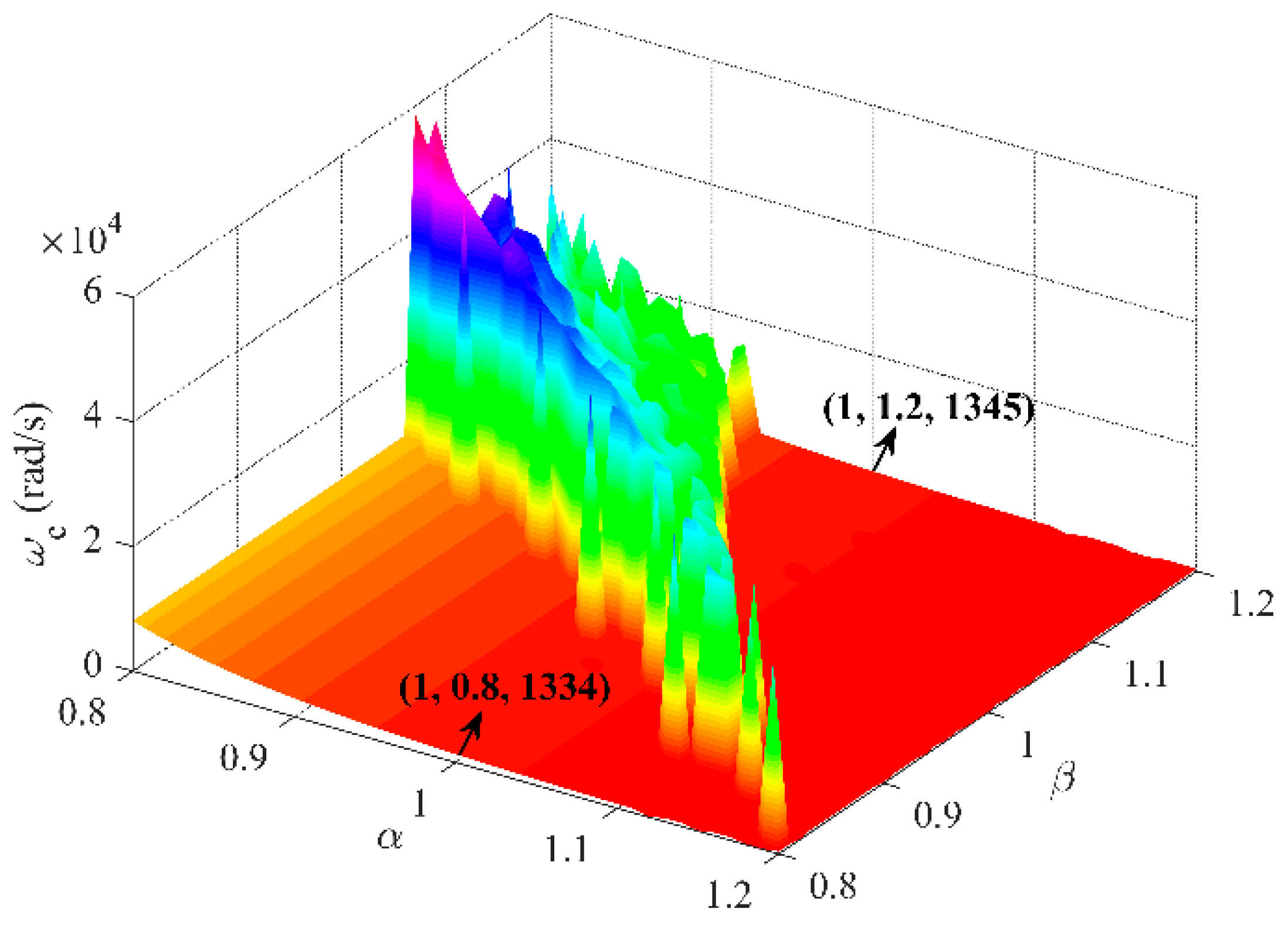
| Center frequency, | is affected by both and . | ||
| Phase-frequency characteristic, | is only determined by when , while is affected by both and when . The high-frequency phase curve changes from to the more lagging direction when , and to the opposite direction when . | ||
| Phase crossover frequency, | If and only if , the phase-frequency characteristics of a fractional-order LCL filter has a . |
Disclaimer/Publisher’s Note: The statements, opinions and data contained in all publications are solely those of the individual author(s) and contributor(s) and not of MDPI and/or the editor(s). MDPI and/or the editor(s) disclaim responsibility for any injury to people or property resulting from any ideas, methods, instructions or products referred to in the content. |
© 2024 by the authors. Licensee MDPI, Basel, Switzerland. This article is an open access article distributed under the terms and conditions of the Creative Commons Attribution (CC BY) license (https://creativecommons.org/licenses/by/4.0/).
Share and Cite
Xu, J.; Zeng, E.; Li, X.; He, G.; Liu, W.; Meng, X. Fractional-Order LCL Filters: Principle, Frequency Characteristics, and Their Analysis. Fractal Fract. 2024, 8, 38. https://doi.org/10.3390/fractalfract8010038
Xu J, Zeng E, Li X, He G, Liu W, Meng X. Fractional-Order LCL Filters: Principle, Frequency Characteristics, and Their Analysis. Fractal and Fractional. 2024; 8(1):38. https://doi.org/10.3390/fractalfract8010038
Chicago/Turabian StyleXu, Junhua, Ermeng Zeng, Xiaocong Li, Guopeng He, Weixun Liu, and Xuanren Meng. 2024. "Fractional-Order LCL Filters: Principle, Frequency Characteristics, and Their Analysis" Fractal and Fractional 8, no. 1: 38. https://doi.org/10.3390/fractalfract8010038
APA StyleXu, J., Zeng, E., Li, X., He, G., Liu, W., & Meng, X. (2024). Fractional-Order LCL Filters: Principle, Frequency Characteristics, and Their Analysis. Fractal and Fractional, 8(1), 38. https://doi.org/10.3390/fractalfract8010038