Article

Nerve Signal Transferring Mechanism and Mathematical Modeling of Artificial Biological System Design

1
Department of Math and Computer Science, University of Advancing Technology, Tempe, AZ 85283, USA
2
Faculty of Sciences and Humanities, State University of New York, Incheon 21985, Republic of Korea
3
School of Artificial Intelligence Convergence, Hallym University, Chuncheon 24252, Republic of Korea
4
Department of Psychiatry, College of Medicine, Hallym University, Chuncheon 24252, Republic of Korea
*
Author to whom correspondence should be addressed.
Fractal Fract. 2024, 8(11), 648; https://doi.org/10.3390/fractalfract8110648
Submission received: 15 September 2024 / Revised: 30 October 2024 / Accepted: 4 November 2024 / Published: 7 November 2024
(This article belongs to the Section Numerical and Computational Methods)

Abstract

:
Our investigation demonstrates the necessity of mathematical modeling and design methodologies for nerve signals in the creation of artificial arms. Nerve impulses vary widely in speed; for example, unmyelinated nerves transmit impulses at around one mile per hour, while myelinated nerves conduct impulses at around 200 miles per hour. The electrical signals originating from the brain, such as those measured by electroencephalography, are translated into chemical reactions in each organ to produce energy. In this paper, we describe the mechanism by which nerve signals are transferred to various organs, not just the brain or spinal cord, as these signals account for the measured amounts of physical force—i.e., energy—as nerve signals. Since these frequency signals follow no fixed pattern, we consider wavelength and amplitude over a particular time frame. Our simulation results begin with the mechanical distinction that occurs throughout the entire process of nerve signal transmission in the artificial arm as an artificial biological system, and show numerical approaches and algebraic equations as a matrix in mathematical modeling. As a result, the mathematical modeling of nerve signals accurately reflects actual human nerve signals. These chemical changes, involving K (potassium), Na (sodium), and Cl (chloride), are linked to muscle states as they are converted into electrical signals. Investigating and identifying the neurotransmitter signal transmission system through theoretical approaches, mechanical analysis, and mathematical modeling reveals a strong relationship between mathematical simulation and algebraic matrix analysis.

1. Introduction

The human body is a highly complex system, intricately connected through neurons, cells, and tissues [1]. This complexity has driven growing interest in studying the body, developing research, and drawing conclusions to address daily life challenges. One part of the human body that has been closely studied over the past few decades is the human arm [2]. The arm is one of the most complex and essential components of the human body, as it plays a crucial role in daily activities.
Like other organs, the human arm is controlled by the brain, with nerve signals transmitting movement information to the hands. These signals can be interpreted and utilized in two ways: by either reading those directly from the brain or extracting nerve signals from a specific point, usually a particular organ. The latter approach is simpler and more efficient, as the brain contains more complex and little understood information.
The significance of human organs, particularly limbs, gained attention after World War II due to the large number of amputees. Since then, researchers have advanced from replacing limbs with wooden prosthetics to conceptualizing mechanical arms controlled by the human brain. In the past decade, global efforts have intensified to replace artificial limbs with robotic arms controlled by brain signals.
The primary goal of this paper is to develop a mathematical model of a human arm that closely resembles natural arm movement by modeling nerve signals through mathematical equations. With the rise of social robots embedded with artificial intelligence, research into the wavelength and amplitude of electrical signals in the nervous system has gained momentum. Our aim is to present our research on the mathematical modeling of human nerve signals that control arm movement. This modeling and design methodology can also benefit other fields, such as rehabilitation, where remote medical attention is required. For example, it could enable the control of an artificial body in a distant location through the same nerve signals. The key challenge will be determining how to transmit human nerve signals over a distance.
Additionally, this study explores alternative methods for generating nerve signals using numerical techniques. Theoretically, mathematics can be used to capture electric signal waves and data. One proposed approach involves reversing the signal. The hypothesis behind this study is that energy or active force can be converted into amplitude and frequency signals. As different elements move, their amplitude and frequency diagrams shift accordingly, potentially explaining nerve signals.
Through this paper, we aim to contribute the following scientific achievements and engineering support:
(i) We clarified muscle contraction on a physiological basis and clarified the electric potential across the cell membrane that occurs inside the body, especially through an artificial arm.
(ii) This investigation theoretically confirmed the anatomy of an artificial arm as an artificial biological system and clearly implemented the mechanical distinction,
(iii) Through mathematical modeling using numerical approaches and algebraic equations, we approached it as a matrix to establish the scientific grounds and foundations for whether nerve signals can be applied to an artificial biological system.
Section 2 provides the research background. Section 3 covers the mechanical analysis of forces acting on artificial arms. Section 4 and Section 5 describe the mathematical simulation and algebraic matrix analysis, respectively. Section 6 discusses a nerve signal transferring mechanism based on a biological system, and Section 7 concludes this investigation.

2. Physiological Basis of Muscle Contraction

Muscle contraction is a complex process that begins with the generation of an electrical signal. The signals originating from the human brain, as detected by electroencephalography, are translated into chemical reactions in various organs to produce energy. This electrical potential opens voltage-gated ion channels in the muscle cell membrane, leading to an increase in intracellular calcium concentration.
In fact, there are many studies that examine the transmission of nerve signals to discover the basis along with the muscle structure. There is a study that investigates efficient nerves [3], and a functional study that newly stretches and regenerates nerve fibers [4]. There is also a new field that studies the time delay of the signal transmission system, and the problems of the transmission system were reported by focusing on the nerve axon [5].
It is important to clarify that the electric potential across the cell membrane does not directly provide the energy required for muscle contraction. Instead, it facilitates the process by opening voltage-gated ion channels, which trigger intracellular signaling pathways. Specifically, the electric potential raises the intracellular calcium concentration, a crucial signal that initiates muscle contraction. The actual energy for contraction is supplied by adenosine triphosphate (ATP) stored within the cell. ATP is hydrolyzed by the actin-myosin complex during the contraction cycle, providing the energy necessary for muscle fibers to contract and generate force. Therefore, while the electric potential starts the signaling cascade that leads to muscle contraction, the energy comes from ATP hydrolysis [2].
In order to control muscle contraction or analyze it for physical and physiological studies, it must be learned through practice in human anatomy. Traditionally, it has been discussed in relation to kinaesthetic signals and muscle contraction [6]. Most recently, it has been expanded to study the molecular structure of muscle–nerve communication that occurs in human bone structure as we age [7]. In addition, active research is being conducted on the physiological muscle contraction of cell membranes and surrounding depolarization [8].
As this research has clarified muscle contraction and physiological mechanisms, our mathematical simulation paper can approach it with scientific basis by establishing more clear governing rules using mathematical modeling of muscle contraction. To this end, it is believed that the ability to create an artificial biological system will advance the implementation of actual artificial arms through scientific advancement and engineering support.
In principle, the main idea of this paper focuses on how neurons and its components are processed of artificial arms (i.e., artificial biological system) by mathematical modeling in a general sense. In particular, it includes nerve signal factors centered on not only mechanical simulations, but also algebraic matrix analysis.
In summary, muscle contraction is initiated by electrical signals but powered by the chemical energy stored in ATP (adenosine triphosphate) molecules.

3. Theoretical Approaches and Problem Statement

This investigation focuses on the design of an artificial arm from the shoulder to the wrist. A typical human arm consists of three primary bones and an elbow joint. These bones are the humerus, radius, and ulna. The humerus forms the upper arm, while the radius and ulna make up the lower arm. Figure 1 illustrates the overall structure of the human arm, viewed from the anterior along the x-axis and z-axis.
Figure 1 shows the overall structure of the human arm bones, including the anterior view along the x-axis and z-axis, highlighting the different parts and movements of the arm. The humeroulnar joint allows for uniaxial rotation, restricting the elbow joint’s movements to flexion (movement of the forearm toward the upper arm) and extension (movement of the forearm away from the upper arm).
This articulation permits the radius and ulna to rotate relative to each other along the longitudinal axis, enabling pronation (the motion from palm-up to palm-down) and supination (the motion from palm-down to palm-up). Flexion and extension involve bending and extending the elbow, with a range of approximately 135° from the vertical line. In this study, −5° is ignored when extending in order to set the vertical line at 0°. Pronation and supination involve the radius rotating around the ulna to turn the hand over, with a 90° limit in each direction. These motions are illustrated in Figure 2.
Our approach to studying the human bones begins with classifying the human body’s mechanical structure. This helps to verify the problem statement, which involves the conversion of chemical elements into electrical signals that form a delivery system. By combining theoretical approaches, mechanical solutions, and mathematical models, we can create mobile robots that walk on four limbs, robots that replicate muscle movement in detail, or even robots capable of expressing human emotions.
As a basic premise, we perform an in-depth survey of the structure of human bones. Through this, we will perform the following mathematical modeling, and during this process, certain biophysical processes will be simplified. Also, it is necessary to find out how these simplified calculations affect the accuracy of the mathematical model.
As explained regarding the structure of the artificial arm, we know the mechanical structure that leads from the shoulder to the hand, we now need to know the structure of the nerve endings.
As is already well known, the basic unit of the nervous system is the neuron [9]. A neuron consists of a neuron cell body where the nucleus is located and has protrusions that extend from it. The dendrites’ function is to receive electrical signals from adjacent neurons, and the axon functions to transmit electrical signals to the next neuron.
We presume that nerve conduction study (i.e., NCS) is performed to check whether electrical signals are transmitted properly in peripheral nerves [10,11]. When electrical stimulation is artificially applied to a normal peripheral nerve, the electrical signal is transmitted along the axon, and a response within the normal range is recorded. Since the algebraic matrix is efficient in transmitting complex multiple variables of a series of muscles and nerve cells, we aim to prove it theoretically and mathematically by modeling it. In order to verify the accuracy of the mathematical modeling, we also measure the accuracy of the transmission values by performing a nerve conduction test. To prove this, individual setups are significant, with a 95% confidence level within ±0.01 of the mean. The transferring mechanism presented in Section 6.2 (Transferring Mechanism) can be statistically proven using the National Health and Nutrition Examination Surveys (NHANES) sample, where population means, standard errors of the means, and percentiles are weighted.
To demonstrate an effective design for the artificial biological system—specifically, an artificial arm—we will present a mechanical analysis based on mathematical modeling and algebraic matrix analysis in detail in Section 4.

4. Mechanical Analysis

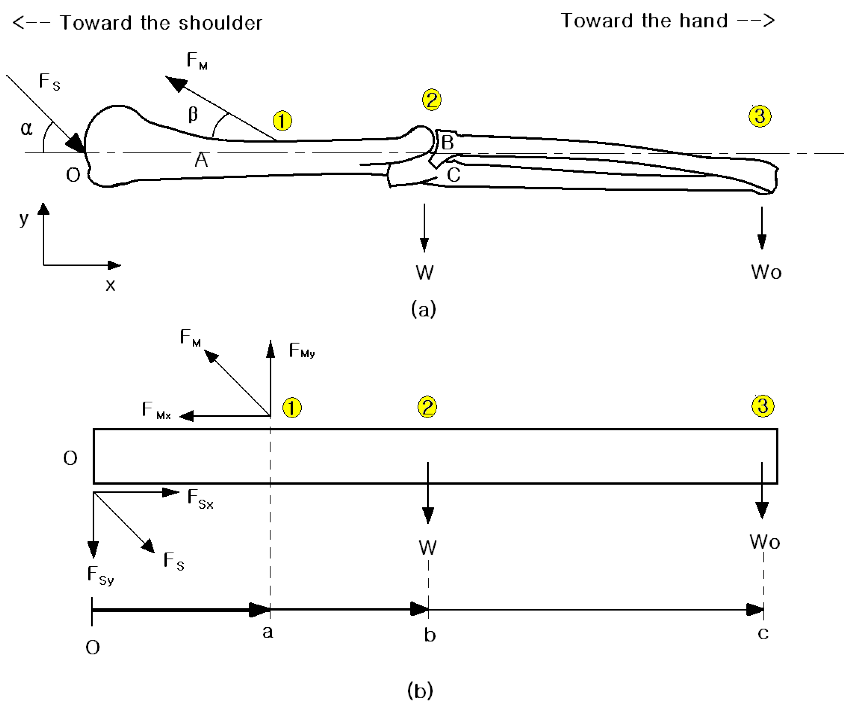
To investigate the electric signal transfer system and moment distribution, we illustrate each diagram step by step. Figure 2a shows a diagram of the human arm with the various forces acting on it, while Figure 2b presents the free-body diagram of the mechanical structure, modeled to closely resemble the real human arm.
In this paper, we define the mechanical analysis of artificial arms designed for physical rehabilitation purposes. Two main forces act on the human arm: the first force is exerted on the muscles at point “a” and is divided into two rectangular components, while the second force is due to the tension on the arm, acting on the shoulder at point “O” as shown in Figure 2.
The forces acting on the arm in a lateral view are resolved into rectangular components along the horizontal and vertical directions. Point O is located at the axis of the shoulder joint. Point ① is where the deltoid and pectoralis major muscles attach to the humerus, point ② represents the center of the entire arm, and point ③ is the end of the arm. W refers to the weight at the center of the arm, while Wo represents the weight of the entire arm. FM is the magnitude of tension in the connecting muscles, and FS is the shoulder joint reaction force. The angle β, measured from the horizontal, relates to the force generated by the connecting muscles.
To calculate the moment, distances between point O and point ① are measured as “a”, point ② as “b”, and point ③ as “c”.
Flexion results in a counterclockwise moment, considered a positive force, while extension creates a clockwise moment, regarded as a negative force. The forces and their directions are defined as follows:
Flexion (Positive): counterclockwise moments
Extension (Negative): clockwise moments
Therefore, the components of the joint reaction force at the shoulder are, as follows:
F S x = F s cos α + x     d i r e c t i o n
F S y = F s sin α y     d i r e c t i o n
The shoulder joint reaction force (Fs) makes an angle α with the horizontal. The direction of the muscle force is considered in the rotational equilibrium of the arm within the shoulder joint at point O. Assuming that the shoulder reaction force does not create torque at point O because its line of action passes through point O, the arm must be in equilibrium, and the sum of all moments (both clockwise and counterclockwise) must be zero. This study neglects the possible contribution of muscle forces on the horizontal component at point O due to this assumption.
The components of the muscle force at the humerus are:
H o r i z o n t a l   c o m p o n e n t :   F M x = F M cos β x
V e r t i c a l   c o m p o n e n t :   F M y = F M sin β + y
thus, at equilibrium, the sum of all moments can be written as:
Clockwise Moments = Anti-clockwise Moments
Thus, the moment can be described as:
B W + c Wo = a FMy
[Moment] = [Force] × [Distance]
∑Mo = 0: a FMy − b W − c Wo = 0
therefore, FMy (vertical component) should be:
F M y = 1 / a b   W + c   W o
The vertical force component of the biceps and deltoid muscles can be determined using Equation (5). Once the vertical component is found, the total force (resultant) exerted by the muscles on the humerus can be determined using Equation (4) by dividing Equation (4) by sin β. As a result, the following equation is obtained:
F M = F M y / sin β
On the horizontal and vertical direction, the components of the net reaction force by the translational equilibrium are:
  F x = 0 :       F s x = F M x
  F y = 0 :       F s x = F M y W W o
After deriving the above two equations, we can now find the values of the two types of forces: the force on the muscles and the reactive force on the shoulder joint along the longitudinal axis, provided that the parameters a, b, c, weights W, and Wo (entire arm weight) are known.
Consequently, in the next Section, we will also examine mechanical equations with coordinate systems by applying two numerical methods: finite difference methods and finite element methods.

5. Mathematical Modeling

5.1. Numerical Approaches

Mathematical models are based on metric systems with specific physical conditions. The metric system is derived by applying fundamental laws (musculoskeletal anatomy) and natural principles, in other words, mechanical analysis that governs the system’s volume. The equations in this design address the balance of mass, force, or energy under certain conditions or parameters. In contrast to analytical solutions, which provide the exact behavior of a design at any point within the system, numerical solutions approximate exact solutions only at discrete points, known as nodes [12].
To investigate artificial biological systems, such as the arm, two numerical methods are commonly used: (i) finite difference methods [8] and (ii) finite element methods [12]. The finite difference method uses a system of difference equations to approximate derivatives, while the finite element method constructs a system of algebraic equations [12]. In this paper, the mathematical formulation of the physical process requires the finite element method for numerical analysis of the mathematical model.
The finite difference method utilizes integral formulations more frequently than the finite element method to create a system. Conversely, the finite element method assumes an approximate continuous function at each element. By modeling with these two traditional approaches, the mechanical design of the artificial arm is validated, demonstrating the design’s effectiveness, which is the objective.
The modeling procedure is as follows: initially, the numerical analysis of the mathematical model involves a pre-processing phase that includes (i) assuming a solution that approximates the behavior of an element, (ii) assembling the elements to represent the entire problem and applying boundary and physical conditions, and (iii) solving a system of algebraic equations [12].
First, the mechanical and mathematical analysis assumes a solution that approximates the behavior of an element. Figure 3 illustrates the subdivision of the problem into nodes and elements.
The humerus, radius, and ulna are typically modeled using eight-node brick elements; however, this study simplifies the model by using two-node brick elements for each component. While a greater number of nodes would provide more accurate results, it would significantly increase the computational workload. Each of the two nodes in this simplified model have three translational degrees of freedom (DoF) along the x, y, and z dimensions [9]. This study disregards the contribution of shear stresses due to the problem being statically indeterminate. The element model in this study accounts for reaction forces (weight stresses) and moments at the end of the nodes, using two nodes per element to represent the problem.
Figure 3 shows the design method for the mathematical three-dimensional modeling of (A) the humerus, (B) the radius, and (C) the ulna ●. Furthermore, it is essential to investigate the relationships between these bones. This requires research about the coordination and angles, including the nodes. Table 1 illustrates the relationship between the elements and their corresponding nodes. Each bone element (A, B, and C) responds to angles between 0° and 135° in the x and y planes. Angle ω (angle ω) corresponds to different coordination phases in the y and z planes, showing the rotational angle of the wrist.
Table 1 categorizes the elements into A, B, and C, with each bone considered as an element and the joint connecting members as nodes. Each bone can be modeled with six nodes and three elements. At each node, there are three force equations, resulting in an 18 × 18 transformation matrix, with 18 × 1 displacement vectors and 18 × 1 force components.
The finite element formulation is:
Ϝ = Τ Κ Τ 1 U
where, T is the transformation matrix, K is the equivalent stiffness matrix, and T−1 is the inverse of the transformation matrix [T], U represents the displacements of the nodes. Additionally, F denotes the components of forces acting on the nodes with global coordinates.

5.2. Algebraix Equations with Matrix

A system of algebraic equations based on Equations (1) and (2) is used to solve for the displacements through the transformation matrix.
The solution is obtained using the principle of superposition [4] and Gaussian elimination.
x t = C 1 X 1 t + C 2 X 2 t + + C n X n t
y = C 1 Y 1 + C 2 Y 2 + + C n Y n
Therefore, algebraic equations are:
Y x = Κ C 1 cos 2   A + C 2 sin A cos A + C 3 0 C 4 cos 2   A C 5 sin A cos A + C 6 0
Y   x = Κ C 1 sin A cos A + C 2 sin 2   A + C 3 0 C 4 sin A cos A C 5 cos 2   A + C 6 0
Y x = Κ C 1 0 + C 2 0 + C 3 1 C 4 0 C 5 0 + C 6
Y x = Κ C 1 cos 2   A C 2 sin A cos A + C 3 0 + C 4 cos 2   A + C 5 sin A cos A + C 6 0
Y x = Κ C 1 sin A cos A C 2 sin 2   A + C 3 0 + C 4 sin A cos A + C 5 sin 2   A + C 6 0
Y x = Κ C 1 0 + C 2 0 + C 3 0 C 4 0 C 5 0 + C 6 1
where A is response a certain angle, represented by θ, δ, and λ.
Algebraic equations, using Wronskians of solutions [13,14] at angles of 0°, 45°, 90°, and 135°, can be used to obtain results corresponding to the active signals related to bone movement. These signals represent nerve signals within the context of the mathematical three-dimensional modeling. These mathematical calculations can predict the motion of the arm’s mechanical energy through the assembled elements’ matrices.
Mathematical methods convert algebraic equations into the assembled elements’ matrices.
F ο = A   E   /   L   M   U
Using Figure 1 and Equation (9) along with algebraic equations, the matrix form is considered:
where
A is a cross-sectional area of element (bone)
E is modulus of elasticity
L is length of element (bone)
Secondly, the assembled elements represent the entire problem and apply boundary conditions. The global stiffness matrix is obtained by assembling or summing the individual elements’ matrices:
Assembling [T] and [T −1] from the Equation (9) with algebraic equations is [M]
F i x F i Y F i Z F j X F j Y F j Z = Κ   cos 2 A sin A cos A 0 cos 2 A sin A cos A 0 sin A cos A sin 2 A 0 sin A cos A sin 2 A 0 0 0 1 0 0 0 cos 2 A sin A cos A 0 cos 2 A sin A cos A 0 sin A cos A sin 2 A 0 sin A cos A sin 2 A 0 0 0 0 0 0 1 U i X U i Y U i Z U j X U j Y U j Z
where, A corresponds to a specific angle, represented by θ, δ, and λ.
F i x F i Y F i Z F j X F j Y F j Z = Κ   1 0 0 0 0 0 0 cos 2 ω sin ω cos ω 0 cos 2 ω sin ω cos ω 0 sin ω cos ω sin 2 ω 0 sin ω cos ω sin 2 ω 0 0 0 1 0 0 0 cos 2 ω sin ω cos ω 0 cos 2 ω sin ω cos ω 0 sin ω cos ω sin 2 ω 0 sin ω cos ω sin 2 ω U i X U i Y U i Z U j X U j Y U j Z
where, ω corresponds to a specific angle at Node 5. The assembled elements’ matrices, along with boundary conditions, are applied to the global stiffness matrix.
Therefore, the final equation is:
[ R m } = [ S m ] [ D m ]
where Rm is the reaction matrix form, Sm is the stiffness matrix, Dm is the displacement matrix.

6. Nerve Signal Transferring Mechanism

6.1. Nerve Signal on Biological System

Our scientific investigation and review focus on the precise mathematical modeling of artificial biological systems. This modeling is expected to be a key asset in understanding the nerve signal transmission system for designing artificial arms. In this context, the three major bones of the arm—humerus, radius, and ulna—are used for the mentioned mathematical modeling.
In this paper, we utilize numerical modeling and calculations based on matrix equations, algebraic equations, and the well-known Wronskian methods [15]. In the human body, nerve signals are transmitted as electrical signals converted from chemical signals. Our mathematical modeling simulates this conversion process. Consequently, the converted mathematical nerve signals exhibit four distinct waves: (i) upper primary signals, (ii) upper secondary signals, (iii) lower primary signals, and (iv) lower secondary signals. Each signal, derived from the base results, has an amplitude associated with the secondary signal. Additionally, most primary signals influence the amplitude, causing a slope.
The mathematical modeling and simulation results of this study are completed within three major bones in the human arm. Mathematical calculations, including a matrix, algebraic equations, and Wronskians of solutions, help to obtain digital signal data in mathematical and physical situations. The human nervous system has a complicated loop. Furthermore, human nerve signals are extremely fast and irregular waves because there has been no conclusive research about the meaning of each individual signal wave.
Figure 4 shows that human nerve signal transmission simulation results include amplitude from 0 to 90 degrees, and wavelength from 0 to 90 degrees, respectively. In Figure 4 the pink-colored line starts from amplitude 0 degrees and takes approximately 4.5 ms to develop to 90 degrees continuously. Also, in Figure 4, the blue-colored line represents the wavelength, which starts from 0 degrees and maintains the frequency signal for approximately 2 ms, and then tends to synchronize after the amplitude decreases due to the influence of Figure 4.
After that, one can observe the tendency of human signal transmission where the pink amplitude and the blue wavelength are synchronized and operate through cycles. Our simulation carried out approximately 60 cases. All cases, from case 1 to case 60, contain the basis results of either mathematical or digital signals. All results are affected within 0.27 s (1/60 sec per unit). The mathematical signal has four waves which are (i) upper primary signals, (ii) upper secondary signals, (iii) lower primary signals, and (iv) lower secondary signals.
Each signal from the basis results has simple amplitude on secondary signal. Many primary signal cases have a variable slope via amplitudes. Neurotransmitter signaling systems can account for the impulse signals, so that our simulation results indicate that athletic performance was engaged.
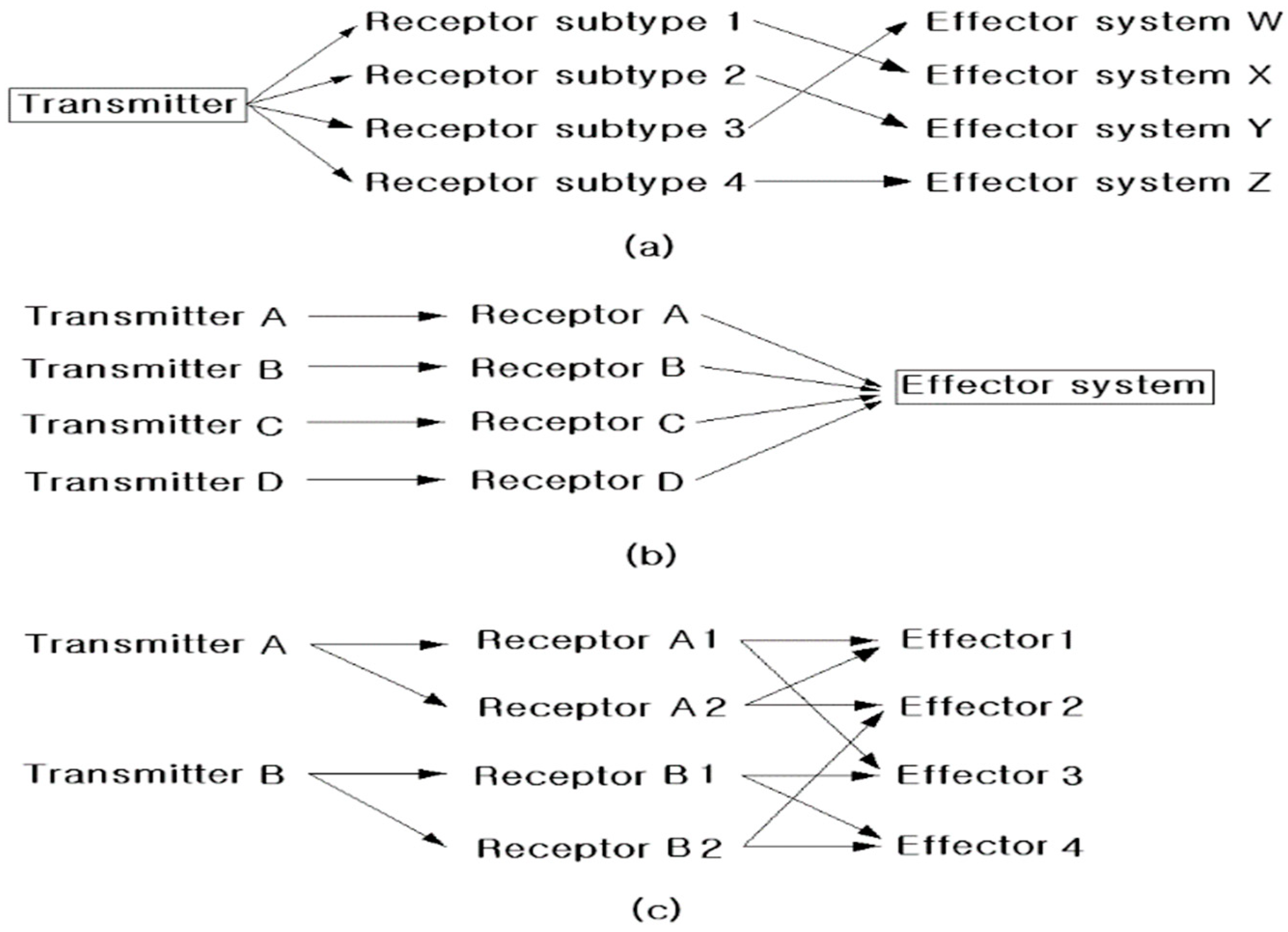
In principal, neurotransmitter signaling systems are (i) divergence, (ii) convergence, and (iii) integrated divergence and convergence [16]. First, divergence is that neurotransmitter can move multiple receptor subtype and then each receptor subtype can apply at effectors system because one neurotransmitter can affect different neurons in various different ways. It can occur at any stage channel. Second, convergence is to have own their receptor type. It can converge to affect the same effectors systems. A single cell in convergence can occur at secondary signal or channel. Third, integrated divergence and convergence can affect receptors and effectors randomly. It does not have any rule for effectors system. The mathematical wave signal types can be fit along various different ways. Simply because the primary signals can be applied at the first position than secondary signals. Throughout the simulation all case 1 to 60, we find out that secondary signals can affect only on the final position [17].
From various scientific sources, we recognize that neurotransmitter signaling systems are responsible for generating impulse signals [17]. The neurotransmitter signaling system operates in three main stages: divergence, convergence, and integration of divergence and convergence. These stages are illustrated in Figure 4. In the divergence stage, neurotransmitters can bind to multiple receptor subtypes, affecting various effector systems, as one neurotransmitter can influence different neurons in diverse ways at any stage of the channel. In the convergence stage, a neurotransmitter binding to its receptor will converge on a single receptor, affecting the same effector systems. Convergence can occur at a secondary signal or channel. Simultaneously, the integrated divergence and convergence stages can affect receptors and effectors randomly, without specific rules governing the effector system.
Mathematical wave signal types can vary in their application. Primary signals can be applied at the initial position, while secondary signals affect only the final position.
Nerve signals exhibit a broad range of speeds; for instance, unmyelinated nerves conduct impulses at about one mile per hour, whereas myelinated nerves can transmit impulses at approximately 200 miles per hour. The electric signals generated by the human brain, as measured by electroencephalography, are translated into chemical reactions at each organ to produce energy.
In this paper, we describe the nerve signal transmission mechanism across various organs, not just in the brain or spinal cord, as we treat the measured amounts of physical force (i.e., energy) as nerve signals. The results of our data analysis reveal the correlation between transmitters, receptors, and effectors, as illustrated in Figure 5. Each subtype (1, 2, 3…, n) is mapped to the effector systems (W, X, Y, Z) in the transmitter for mathematical modeling purposes. Similarly, in the effector system, transmitters (A, B, C, D) are mapped to receptors (A, B, C, D). For example, Transmitter A is connected to Effector 1 and Effector 3, while Transmitter B is connected to Effector 3 and Effector 4 through Receptors B1 and B2. This setup allows for mathematical modeling using methods of divergence, convergence, and integration.
Defining the nerve transmission mechanism is crucial, and the next chapter will provide examples of nerve signal dissemination, considering ion movements.

6.2. Transferring Mechanism

This section presents the results of mathematical modeling, considering the mechanism of nerve signal dissemination, supported by scientific evidence. The method and mechanism of nerve signal transmission involve transforming measured amounts of physical force (i.e., energy) through a signal transfer mechanism.
Since frequency signals do not follow a set pattern, they are analyzed in terms of wavelength and amplitude within a specific period. Consequently, the mathematical modeling of nerve signals aims to accurately reflect human nerve signals. Developing a three-dimensional mathematical model of nerve signals for designing an artificial arm, which closely mimics a real arm, involves a complex procedure.
In this paper, we address three main topics: (i) mechanical analysis, (ii) mathematical modeling, and (iii) biochemical signal transfer mechanisms in neuronal function. While it is well known that the nervous system transmits electrical signals, it is important to note that the electrical charge in the axon’s cytosol is carried by electrically charged atoms (ions) rather than free electrons [12]. The cytosol and extracellular fluid consist of water and ions, with sodium (Na), potassium (K), and chloride (Cl) comprising 99.9% of these ions [14]. Potassium (K) exists primarily in its cationic form and plays a crucial role in neuronal function. It helps adjust the osmotic balance between cells and the interstitial fluid through the Na+/K+ ATPase pump [18]. Sodium (Na+, a cation) and chloride (Cl, an anion) are components of table salt and are held together by the electrical attraction of oppositely charged atoms [19]. Ions are the primary charge carriers involved in electrical conduction in biological systems, including neurons [20].
According to ionic concentrations from the Goldman equation [21], potassium (K) at 100 mM has an energy of −80 mV, sodium (Na) at 15 mM has 62 mV, and chloride (Cl) at 13 mM has −65 mV. The energy values and amplitude magnitudes shown in Table 2 indicate that when potassium and chloride have negative values in ionic concentrations, the amplitude is at a negative state (lower signals) in the results. Conversely, when sodium has positive ionic concentrations, the amplitude is in a positive state.
To understand how the reference energy values are calculated using the Goldman equation, we explore the essential details of this process [22]. The Goldman equation, also known as the Goldman–Hodgkin–Katz voltage equation, calculates the resting membrane potential by considering the permeability of the membrane to various ions, typically potassium (K+), sodium (Na+), and chloride (Cl). The equation is:
V m = R T F ln p k K + o + p N a N a + o + p C l C l i p k K + i + p N a N a + i + p C l C l o
where:
Vm is the resting membrane potential,
R is the gas constant,
T is the absolute temperature in Kelvin,
F is the Faraday’s constant,
P is the permeability coefficient for each ion species,
[X+] in/out [X+] in/out represents the intracellular/extracellular concentration of each ion species.
H = value of the Planck constant (6.626068 × 10⁻³⁴ Js) [23],
Λ = wavelength (Potassium for K; 6.142 × 10⁻¹⁰ m
Sodium for Na; 11.885 × 10⁻¹⁰ m,
Chloride for Cl; 4.7182 × 10⁻¹⁰ m) [24]
m = non-zero rest atomic mass
The Goldman equation accounts for the relative permeability of the membrane to different ions, providing a more accurate representation of the membrane potential compared to the Nernst equation, which considers only one ion at a time. By incorporating the concentrations and permeabilities of multiple ions, the Goldman equation reflects the combined effects of these ions on the membrane potential [25].
Experimental data for these parameters are obtained using techniques such as patch-clamp recordings and fluorescent indicators, ensuring accurate measurements of ion concentrations and membrane potentials [26]. The values in Table 2 are further validated by comparing them with established electrophysiological studies, demonstrating their consistency and reliability. This rigorous approach ensures that our mathematical model accurately represents the physiological processes involved in nerve signal transmission, thereby supporting the study’s overall objectives.
Concluding remarks from the net transmembrane current [1] indicate that when K+ efflux and Cl and Na+ influx occur, the energy has a positive value, and the amplitude is in a positive state. During this stage, the muscle extends. Table 3 presents the muscle status for each circumstance. The upper and lower amplitude signals from the base results and results can predict muscle states. Additionally, the area between the zero line and the signal boundary line estimates the amount of energy.
When an arm moves, two types of movement occur simultaneously, extension and flexion. Extending activity in muscles is indicated by lower signals in the base results and when Cl and Na+ flow into the cell and K+ flows out. For example, extending muscles such as the triceps brachii (long head), brachioradialis, flexor carpi radialis, palmaris longus, and pronator teres in Case 32 are affected by these lower amplitude signals. The area between the zero line and the lower signals reflects the properties of Cl and Na+ flow out of the cell, resulting in muscle contraction [27]. Upper signals in amplitude with K+ efflux also affect the muscles. Flexing muscles include the biceps brachii, brachialis, brachioradialis, deltoid, extensor carpi radialis longus, and triceps brachii lateral head in case 32. When K+ flows into the cell, the muscles contract. In this case, the property of lower signals is observed [21]. Conversely, when signals (upper signals) exceed the zero line, Cl and Na+ flow out of the cell, resulting in muscle contraction.
Determining upper and lower signals simultaneously based on initial and final result data can be challenging due to varying physical conditions. Signal definitions related to energy or force application are analyzed differently in the base results and outcomes.
The initial and final results vary due to diverse physical situations. Initial results represent raw data without individual adjustments [28]. Each person has unique size, weight, muscle structure, and arm movement, which necessitates adjustments for physical conditions. Consequently, results are considered in relation to base results and individual setups. Defining average individual setups is complex. Statistically, data from individual setups are significant, with a 95% confidence level within ±0.01 of the mean [29]. Population means, standard errors of the means, and percentiles are weighted using National Health and Nutrition Examination Surveys (NHANES) sample weights to produce national estimates [30]. When calculating the data, the uncertainty of error is rounded to the nearest decimal point, typically to four decimal places.
It should be noted that we need to know more about the modeling equation constraints. There are many multi-variables including signals, movements, and chemicals. If the charges of positive and negative ions are equal inside the human body (this can be called the constraints of the equations presented in Equations (18)–(21), respectively in Section 6.1), it becomes electrically neutral. However, the cytoplasm inside the axon has a negative charge of −70 mV in the resting state. The subject of our thesis is to elucidate this membrane potential, and if this is applied to an actual arm, the electrophysiological elucidation of nerve cells can be realized through computer simulation, which can lead to the creation of a natural robot for an actual arm.
As previously mentioned, there are two methods to read and utilize nerve signals: either by obtaining them from the brain or by extracting nerve signal information at a specific location, typically from a particular organ. The latter approach is often more efficient and straightforward, as it avoids the complexity and uncertainty associated with the brain’s more intricate and less understood information.
During the nerve conduction process in the axon, the activation gate, m gate, and the inactivation gate, h gate, open simultaneously or only to one side. When this reaches minus 70 mV to 30 mV, the membrane potential closes, increasing the speed of nerve signal transmission. If this rapid effect is applied to an actual arm, we can see scientific progress.
To be more specific, the membrane potential changes over time in response to variations in frequency and amplitude. Typically, the rising phase of the action potential is due to the influx of Na+ ions through sodium channels [31]. Conversely, the falling phase results from the inactivation of sodium channels and the efflux of K+ ions through potassium channels.
In this case, the action voltage generated by nerve cells is a small electrical spike of about 0.1 V that occurs for approximately 1/1000 of a second, and this electrical signal is transmitted through the nerve bundle at a maximum speed of 100 m per second [32]. As discussed earlier in the introduction, myelinated nerves conduct impulses at around 200 miles per hour. At this time, the inner axon where the electrical signal is transmitted and the myelin sheath surrounding it are distinguished.

7. Conclusions

Many researchers and scientists are working on constructing artificial arms that closely mimic real human arms, yet few have focused on accurately modeling human nerve signals. This paper presents a method for the mathematical modeling of human nerve signals and their transfer mechanisms. Once human nerve signals are accurately modeled mathematically, controlling artificial arms becomes significantly more feasible.
By investigating and identifying the neurotransmitter signal transfer system through theoretical approaches, mechanical analysis, and algebraic matrix modeling, a strong relationship between stimulation and analysis is established. Chemical changes, such as those involving K+, Na+, and Cl, are linked to muscle states as they are converted into electrical signals.
Our study focuses on the mathematical modeling of nerve signals using finite element methods, theoretical approaches, mechanical analysis, and mathematical modeling. We describe the nerve signal transfer mechanism at each organ, not just in the brain or spinal cord, by treating measured amounts of physical force (i.e., energy) as nerve signals. The results of our data analysis reveal correlations between the transmitter, receptor, and effector systems.
In our mathematical approaches to test biological systems, Transmitter A is connected to Effector 1 and Effector 3, while Transmitter B connects to Effector 3 and Effector 4 through Receptors B1 and B2. This paper introduces new mathematical modeling approaches and numerical equations. We propose a new methodology for neurotransmitter signal modeling with algebraic equations that conjecture an approximate continuous function for each element. We are conducting experiments to apply the mathematical model we proposed to an actual artificial arm with an actual body catheter, and are studying how to control it by applying it. This paper is being prepared to be published as a series of three subsequent papers.
Additionally, this paper mathematically demonstrates that nerve transmitter signals can be represented as physical forces, similar to electric signals or their energy forms, analogous to human nerve signals.

Author Contributions

J.P. conducted the model’s data analysis, developed stimuli and writing—original draft preparation; S.Y. interpreted the results; T.J. supervised the project, and writing—review and editing. All authors have read and agreed to the published version of the manuscript.

Funding

This research was supported by Hallym University Research Fund, 2024(HRF-202407-003). This research was supported by Hallym University MHC (Mighty Hallym 4.0 Campus) project, 2024 (MHC-202402-005).

Data Availability Statement

Data available on request due to restrictions, e.g., privacy or ethical.

Conflicts of Interest

The authors declare no conflicts of interest.

References

  1. Bear, M.F.; Connors, B.W.; Paradiso, M.A. Neuroscience Exploring the Brain, 2nd ed.; Lippincott Williams & Wilkins: Baltimore, Maryland, 2001. [Google Scholar]
  2. Bloch, S.C. Excel for Engineers and Scientists, 2nd ed.; John Wiley and Sons, Inc.: New York, NY, USA, 2003. [Google Scholar]
  3. Wei, H.; Shi, R.; Sun, L.; Yu, H.; Gong, J.; Liu, C.; Xu, Z.; Ni, Y.; Xu, J.; Xu, W. Mimicking efferent nerves using a graphdiyne-based artificial synapse with multiple ion diffusion dynamics. Nat. Commun. 2021, 12, 1068. [Google Scholar] [CrossRef] [PubMed]
  4. Wang, C.; Liu, Y.; Qu, X.; Shi, B.; Zheng, Q.; Lin, X.; Chao, S.; Wang, C.; Zhou, J.; Sun, Y.; et al. Ultra-stretchable and fast self-healing ionic hydrogel in cryogenic environments for artificial nerve fiber. Adv. Mater. 2022, 34, 2105416. [Google Scholar] [CrossRef] [PubMed]
  5. Singleton, B.; Alkahby, H. Observation of Signal Transmission on the Nerve Axon with time delay. Int. J. Evol. Equ. 2011, 6, 319. [Google Scholar]
  6. Gandevia, S.C.; McCloskey, D.I.; Burke, D. Kinaesthetic signals and muscle contraction. Trends Neurosci. 1992, 15, 62–65. [Google Scholar] [CrossRef] [PubMed]
  7. Soendenbroe, C.; Andersen, J.L.; Mackey, A.L. Muscle-nerve communication and the molecular assessment of human skeletal muscle denervation with aging. Am. J. Physiol.-Cell Physiol. 2021, 321, C317–C329. [Google Scholar] [CrossRef] [PubMed]
  8. Gash, M.C.; Kandle, P.F.; Murray, I.V.; Varacallo, M. Physiology, muscle contraction. In StatPearls [Internet]; StatPearls Publishing: Treasure Island, FL, USA, 2023. [Google Scholar]
  9. O’Bryan, R.; Kincaid, J. Nerve conduction studies: Basic concepts and patterns of abnormalities. Neurol. Clin. 2021, 39, 897–917. [Google Scholar] [CrossRef] [PubMed]
  10. Lanigan, L.G.; Russell, D.S.; Woolard, K.D.; Pardo, I.D.; Godfrey, V.; Jortner, B.S.; Butt, M.T.; Bolon, B. Comparative pathology of the peripheral nervous system. Vet. Pathol. 2021, 58, 10–33. [Google Scholar] [CrossRef] [PubMed]
  11. Cuccurullo, S.J. (Ed.) Physical Medicine and Rehabilitation Board Review; Demos Medical Pub: New York, NY, USA, 2004. [Google Scholar]
  12. Souza, M.L.; Freitas, C.F.; Domingos MA, O.; Nunes-Tavares, N.; Hasson-Voloch, A.; Nasciutti, L.E.; Silva, L.C.F. Identification and distribution of chondroitin sulfate in the three electric organs of the electric eel, Electrophorus electricus (L.). Comp. Biochem. Physiol. Part B Biochem. Mol. Biol. 2007, 146, 227–233. [Google Scholar] [CrossRef] [PubMed]
  13. Garcia, A.L. Numerical Methods for Physics; Prentice Hall: Hoboken, NJ, USA, 1994. [Google Scholar]
  14. Edwards, C.H.; Penney, D.E. Elementary Differential Equations with Boundary Value Problems, 4th ed.; Upper Saddle River & Prentice-Hall, Inc.: Hoboken, NJ, USA, 2000; pp. 101–365. [Google Scholar]
  15. Natanson, G. X-Jacobi Differential Polynomial System Formed by Solutions of Heun Equation at Fixed Values of Accessory Parameter. 2018. Available online: https://www.researchgate.net/profile/Gregory-Natanson/publication/327235393_X1-Jacobi_Differential_Polynomial_System_Formed_by_Solutions_of_Heun_Equation_at_Fixed_Values_of_Accessory_Parameter/links/6663410ca54c5f0b9456679a/X1-Jacobi-Differential-Polynomial-System-Formed-by-Solutions-of-Heun-Equation-at-Fixed-Values-of-Accessory-Parameter.pdf (accessed on 3 November 2024).
  16. Hatfield, B.D.; Jaquess, K.J.; Lo, L.C.; Oh, H. The cognitive and affective neuroscience of superior athletic performance. In Handbook of Sport Psychology; John Wiley & Sons, Inc.: Hoboken, NJ, USA, 2020; pp. 487–512. [Google Scholar]
  17. Park, J. Mathematical Modeling of Nerves Signal on the Design of Artificial Arms. Ph.D. Dissertation, University of Advancing Technology, Tempe, AZ, USA, 2009. [Google Scholar]
  18. Mermelstein, C.; Costa, M.; Neto, V. The cytoskeleton of the electric tissue of Electrophorus electricus, L. Ann. Acad. Bras. Cienc. 2000, 72, 341351. [Google Scholar] [CrossRef] [PubMed]
  19. Rosenberg, R.L.; Tomiko, S.A.; Agnew, W.S. Single-channel properties of the reconstituted voltage-regulated Na channel isolated from the electroplax of Electrophorus electricus. Proc. Natl. Acad. Sci. USA 1984, 81, 55945598. [Google Scholar] [CrossRef] [PubMed]
  20. Keynes, R.; Ferreira, H. Membrane potentials in the electroplates of the electric eel. J. Physiol. 1953, 119, 315351. [Google Scholar] [CrossRef] [PubMed]
  21. Gotter, A.; Kaetzel, M.; Dedman, J. Electrophorus electricus as a model system for the study of membrane excitability. Comp. Biochem. Physiol. 1998, 119, 225–241. [Google Scholar] [CrossRef] [PubMed]
  22. Jeong, T. Time-series Data Classification and Analysis associated with Machine Learning Algorithms for Cognitive Perception and Phenomenon. IEEE Access 2020, 8, 222417–222428. [Google Scholar] [CrossRef]
  23. Sherif, K.; Nachbagauer, K.; Steiner, W. On the rotational equations of motion in rigid body dynamics when using Euler parameters. Nonlinear Dyn. 2015, 81, 343–352. [Google Scholar] [CrossRef] [PubMed]
  24. Henry Moseley Finds a Property to Justify the Term Atomic Number. Available online: http://www.rsc.org/education/teachers/learnnet/periodictable/ (accessed on 3 November 2024).
  25. Logg, A. Automating the finite element method. Arch. Comput. Methods Eng. 2007, 14, 93–138. [Google Scholar] [CrossRef]
  26. Malak, D.; Akan, O.B. Communication theoretical understanding of intra-body nervous nanonetworks. IEEE Commun. Mag. 2014, 52, 129–135. [Google Scholar] [CrossRef]
  27. Web Associates. Anthropometric Source Book. National Aeronautics and Space Administration I (NASA no. 1024). 1978. Available online: https://ntrs.nasa.gov/citations/19790003563 (accessed on 3 November 2024).
  28. Weir, R.F. Design of Artificial Arms and Hands for Prosthetic Applications: Standard Handbook of Biomedical Engineering and Design; McGraw-Hill Standard Handbooks: New York, NY, USA, 2003. [Google Scholar]
  29. Ewart, H.S.; Klip, A.M.I.F.U. Hormonal regulation of the Na (+)-K (+)-ATPase: Mechanisms underlying rapid and sustained changes in pump activity. Am. J. Physiol.-Cell Physiol. 1995, 269, C295–C311. [Google Scholar] [CrossRef] [PubMed]
  30. McDowell, M.A.; Fryar, C.D.; Ogden, C.L.; Flegal, K.M. Anthropometric reference data for children and Adults: United States, 2003–2006. Natl. Health Stat. Rep. 2008, 10, 5. [Google Scholar]
  31. Saeed, M. Three-Dimensional Elements Finite Element Analysis, Theory and Application with ANSYS; Prentice Hall: Hoboken, NJ, USA, 1999. [Google Scholar]
  32. Gordon, A.M.; Huxley, A.F.; Julian, F.J. The variation in isometric tension with sarcomere length in vertebrate muscle fibers. J. Physiol. 2000, 184, 170–192. [Google Scholar] [CrossRef] [PubMed]
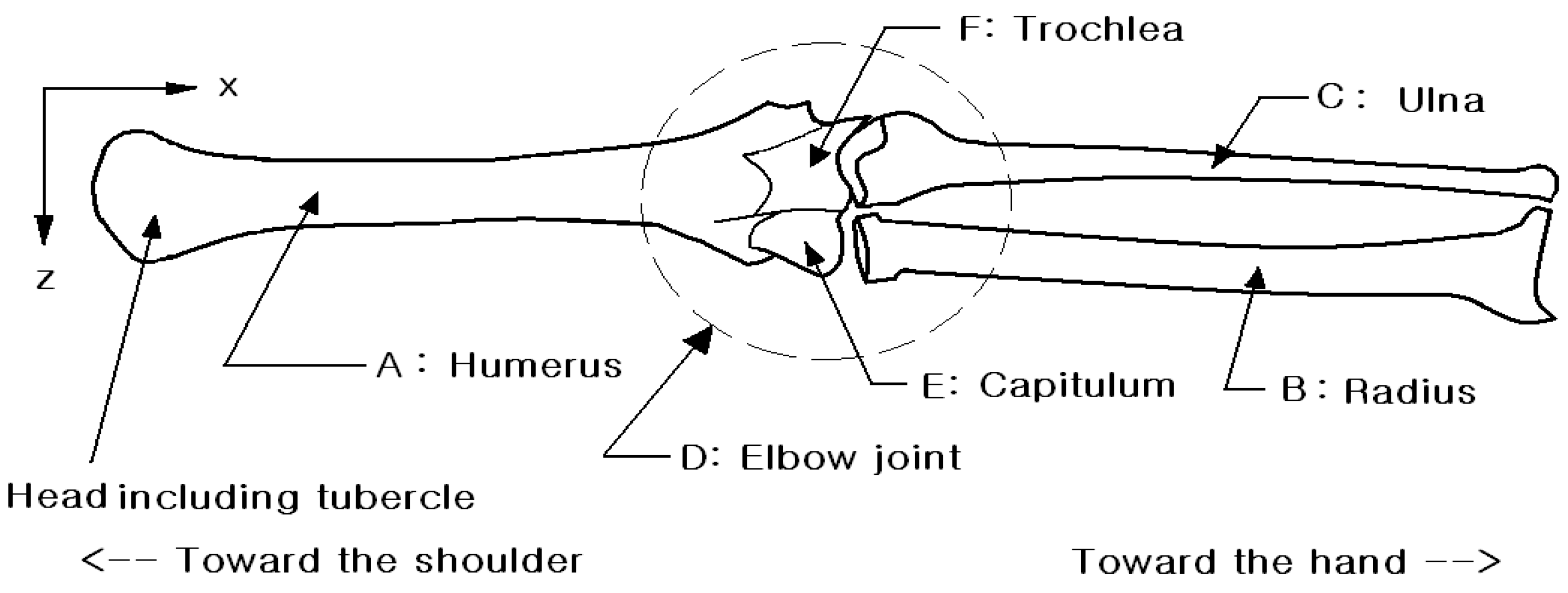
Figure 1. Overall structure of human bone, anterior view of x-axis and z-axis.
Fractalfract 08 00648 g001
Figure 2. (a) The forces acting on the arm and (b) the free-body diagram of the arm. (A) Humerus, (B) radius, (C) ulna. a, b, and c are distances from point O.
Fractalfract 08 00648 g002
Figure 3. Design method for mathematical three-dimensional modeling. (A) Humerus, (B) radius, (C) ulna ●. In this figure, node (a) subdivides the bones into the bar of elements and nodes. (b) The two nodes use brick elements in three-dimensional modeling. (c) The global coordinates system and vector.
Fractalfract 08 00648 g003
Figure 4. Human nerve signal transmission simulation results which include amplitude 0 to 90 degrees and wavelength 0 to 90 degrees angle, respectively. (a) Pink-colored amplitude 0 to 90 degrees, (b) Blue-colored wavelength 0 to 90 degrees in the x-axis (time) and y-axis (frequency signal).
Fractalfract 08 00648 g004
Figure 5. Divergence and convergence in neurotransmitter (a) divergence stage, (b) convergence stage, (c) integrated divergence and convergence stage.
Fractalfract 08 00648 g005
Table 1. Relationship between the elements and their corresponding nodes.
BoneElementNode (i)Node (j)CoordinationAngle (°)
Humerus (θ)A12x, y0, 45, 90
Radius (δ)B35x, y0, 45, 90, 135
Ulna (λ)C46x, y0, 45, 90, 135
Radius and Ulna (ω)B and C56y, z0, 90, 180
Table 2. Energy relates with amplitude and ionic concentrations.
Potassium (K)Sodium (Na)Chloride (Cl)
Ionic concentrations (M), [1]1.00 × 101.50 × 10−11.30 × 10⁻¹
Reference energy (eV), [1]−0.80.62−0.65
Calculated energy (eV)−0.561.69−0.804
AmplitudeNegativePositiveNegative
Table 3. Muscles state on circumstances.
Muscle StateIonsFlow DirectionInside the Membrane EnergyAmplitude
ExtendK+EffluxIncreasePositive
ClInfluxDecreaseNegative
Na+Negative
FlexK+InfluxDecreaseNegative
ClEffluxIncreasePositive
Na+Positive
Disclaimer/Publisher’s Note: The statements, opinions and data contained in all publications are solely those of the individual author(s) and contributor(s) and not of MDPI and/or the editor(s). MDPI and/or the editor(s) disclaim responsibility for any injury to people or property resulting from any ideas, methods, instructions or products referred to in the content.