Article

Robust Speed Control of Permanent Magnet Synchronous Motor Drive System Using Sliding-Mode Disturbance Observer-Based Variable-Gain Fractional-Order Super-Twisting Sliding-Mode Control

1
College of Mechatronics and Control Engineering, Shenzhen University, Shenzhen 518060, China
2
Department of Electrical Engineering, Quid-e-Azam College of Engineering & Technology Sahiwal, Sahiwal 57000, Pakistan
*
Authors to whom correspondence should be addressed.
Fractal Fract. 2024, 8(7), 368; https://doi.org/10.3390/fractalfract8070368
Submission received: 26 March 2024 / Revised: 7 June 2024 / Accepted: 13 June 2024 / Published: 24 June 2024

Abstract

:
This paper proposes a novel nonlinear speed control method for permanent magnet synchronous motors that enhances their robustness and tracking performance. This technique integrates a sliding-mode disturbance observer and variable-gain fractional-order super-twisting sliding-mode control within a vector-control framework. The proposed control scheme employs a sliding-mode control method to mitigate chattering and improve dynamics by implementing fractional-order theory with a variable-gain super-twisting sliding manifold design while regulating the speed of the considered motor system. The aforementioned observer is suggested to enhance the control accuracy by estimating and compensating for the lumped disturbances. The proposed methodology demonstrates its superiority over other control schemes such as traditional sliding-mode control, super-twisting sliding-mode control, and the proposed technique. MATLAB/Simulink simulations and real-time implementation validate its performance, showing its potential as a reliable and efficient control approach for the system under study in practical applications.

1. Introduction

Permanent magnet synchronous motors (PMSMs) have attracted substantial interest across various industrial applications, ranging from low- to mid-power requirements to high-power drives, including wind power systems, electric vehicles, robotics, aerospace, and CNC machine tools. Their popularity compared to induction-type and brush-type motors stems from their inherent advantages such as increased air-gap flux density, high power density, minimized rotor inertia, compact designs, and improved efficiency [1,2]. However, the operational dynamics of practical PMSM systems represent a classic example of a multivariable, strongly coupled nonlinear system. The efficacy of control methodologies for such systems is substantially influenced by a spectrum of uncertainties encompassing unmodeled dynamics, variations in model parameters, external load disturbances, and frictional effects [3]. Consequently, the development of robust control algorithms holds significant promise for widespread applications.
The inherent difficulty in achieving high-performance control of PMSM systems using conventional techniques, such as Jacobian linearization and proportional–integral–differential (PID) control, is due to the intricate nature of the system dynamics and the presence of multiple uncertainties [4]. Therefore, numerous researchers have devoted effort to devising control algorithms to mitigate the deterministic nonlinearities inherent in PMSM models. Feedback linearization techniques have gained significant attention as effective approaches for addressing the challenges posed by disturbances and uncertainties [5]. Meanwhile, the advent of digital control processors has further promoted the adoption of model predictive control (MPC) in motor control owing to its ability to perform online optimization and flexibility in incorporating constraints [6,7]. Although feedback linearization and MPC effectively manage the deterministic nonlinearities of PMSM models, eliminating the adverse effects resulting from uncertainties remains a challenging task [4]. Numerous nonlinear control schemes have been proposed and implemented to enhance the performance of nonlinear control systems under various operating conditions. These methods include active disturbance rejection control [8], robust control [9], backstepping control [10,11], sliding-mode control (SMC) [12,13], intelligent control [14], and adaptive control [15].
SMC is a widely recognized nonlinear control method that is renowned for its robustness against fluctuations in internal parameters and external disturbances. This technique displays impressive tracking performance, even when uncertainties exist in the system parameters and external interference. Its ease of implementation, minimal overshoot, robustness, effective disturbance rejection, and quick response make it a preferred choice for various motor applications including PMSMs [16]. Previous studies have demonstrated the effectiveness of SMC across multiple motor systems. For instance, a fuzzy SMC approach has been successfully applied to a six-phase induction machine [17], whereas an improved sliding-mode observer (SMO) has been proposed for sensorless control of PMSMs and IMs [18,19]. Additionally, the use of neuro-fuzzy SMC techniques in induction machines has been validated [20].
However, a prominent drawback of SMC methods is the occurrence of chattering, which arises owing to the discontinuous nature of the control law and frequent switching actions near the sliding surface [21]. This limitation poses a challenge for the practical implementation of SMC in real-world systems. Various strategies have been developed for mitigating or alleviating the effects of chattering. These approaches include high-order sliding-mode control (HOSMC) techniques [22], complementary SMC [23], different sign function approximations (although these approaches can alleviate the chattering phenomenon, they are at the expense of anti-disturbance performance) [24], and utilizing the reaching law algorithm [25]. The methods outlined in Figure 1 effectively demonstrate their capacity to reduce chattering and increase the usefulness of SMC in real-world applications. Another strategy employed to mitigate chattering involves reducing switching gain. However, this method has two notable drawbacks: it compromises the controller’s reaching time; and if the switching gain is set below the upper bound of the disturbances, the complete rejection of disturbances becomes unattainable [26].
To mitigate the adverse effects of disturbances and enhance the robustness of control systems, a promising approach involves leveraging disturbance observer technology within traditional SMC frameworks [27]. This method actively observes and compensates for integrated disturbances without compromising the closed-loop system performance, significantly improving robustness. Furthermore, HOSMC techniques have been developed as extensions of first-order SMC to reduce chattering effects. These methodologies utilize higher-order derivatives of a sliding manifold to address challenges such as high-frequency chattering and improve robustness, which are particularly beneficial for electric drives [28].
Recent studies have further explored various observer-based methods to enhance the control system performance. For instance, advanced disturbance observer designs, such as extended state observer (ESO), have been integrated with SMC to improve disturbance estimation and rejection capabilities in PMSM control systems [29]. These methods have significantly improved the handling of uncertainties and external disturbances, enhancing the overall robustness and stability of PMSM drives [30].
A notable advancement in the HOSMC domain is the second-order sliding-mode control algorithm, which mitigates chattering while maintaining the core benefits of classical sliding-mode approaches, including robustness, simplicity, and finite-time convergence [31]. Among second-order SMC algorithms, the super-twisting algorithm (STA) is highly effective [32]. However, conventional STAs exhibit homogeneous characteristics and often overlook the uncertainties and disturbances arising from state variable fluctuations [33]. To address this limitation, Lyapunov-based variable-gain super-twisting (VGST) techniques have been introduced as nonhomogeneous extensions of STA, effectively managing uncertain disturbances bounded by known functions [34]. VGSTSMC, an evolution of STA, incorporates variable parameters to compensate for uncertainties and disturbances, thereby enhancing system robustness [34]. Despite these advantages, the primary challenge remains in determining the boundary functions for uncertainties and disturbances within VGSTSMC, which complicates the design of controllers for practical PMSM applications. Addressing this issue and developing efficient methods to ascertain the boundary functions are crucial research areas for fully exploiting VGSTSMC’s potential of VGSTSMC in practical electric drive systems, particularly for PMSM applications.
However, the primary constraint of these types of STAs is their slow response, which is attributed to the use of linear sliding manifolds. To overcome this problem, researchers have proposed advanced sliding manifolds such as the integral sliding manifold, leading to the development of an integral super-twisting algorithm [35]. Although this control algorithm promises a fast response on a sliding manifold, it often exhibits significant overshoot. To address this issue, fractional-order sliding surfaces (FOSSs) have emerged as an effective control scheme [36]. By expanding the integer-order sliding manifold, FOSSs provide a fast response and minimal overshoot in dynamics [37]. Studies demonstrated that the use of FOSSs can mitigate chattering [38]. This technique has been incorporated into many mechatronic systems because of its numerous advantages, resulting in exceptional performance [39]. Based on this concept, a new constant-gain fractional-order super-twisting scheme has been developed [40]. However, relying solely on constant gains implies that the controller cannot adequately counteract the uncertain disturbances.
The primary goal of this study is to design a sliding-mode control strategy using a variable-gain fractional-order super-twisting sliding-mode control (VGFOSTSMC) method for PMSM speed-regulation systems that meet specific requirements. The control law must satisfy the following conditions:
  • Responsively track the reference signal while minimizing steady-state error, overshoots, and settling times.
  • Demonstrate robust performance in the presence of uncertain disturbances.
  • Possess a relatively straightforward design process.
In pursuit of these objectives, this research introduces the VGFOSTSMC. This novel control mechanism employs fractional-order (FO) calculus to establish its sliding manifold, ensuring the swift attainment of state equilibrium and minimal overshoot. Moreover, the controller integrates variable gains to mitigate the chattering phenomenon. To enhance the robustness of the control system against disturbances, an observer-based approach is introduced in the feedforward significance of this study as follows:
1.
A unique FOSS is formulated and disseminated. Including a specific term accelerates convergence to the sliding manifold, enabling the controller to demonstrate improved performance without additional tunable parameters.
2.
Introducing a new variable-gain super-twisting sliding-mode control law enables the system state to swiftly approach the sliding manifold, regardless of the initial position. Additionally, the proposed reaching law effectively mitigates high-frequency chattering, which is an undesirable phenomenon in SMC.
3.
Proposing a sliding-mode disturbance observer (SMDO) to enhance the disturbance rejection capabilities of the VGFOSTSMC method. The estimated system disturbance is used for the feedforward of the speed controller.
4.
Developing a new sliding-mode speed controller rooted in the advancements above; this controller integrates an adaptive disturbance estimator/observer to offset the outputs of the enhanced sliding-mode-based speed controller. The method ensures finite-time convergence and exhibits higher precision, stronger robustness, and reduced chattering compared to conventional SMC.
5.
The study showcases the effectiveness of the proposed VGFOSTSMC method in regulating PMSM speed through simulations and experimental results.
The remainder of this paper is organized as follows. In Section 3, the mathematical model of a PMSM is discussed in detail. Section 4 focuses on the design of the VGFOSTSMC and SMDO and its stability analysis. In Section 5, the simulations and experimental results of the proposed VGFOSTSMC and SMDO are presented and analyzed. The final section provides concluding remarks and summarizes the key findings and contributions of this study.

2. Preliminaries

The main objective of this study is to achieve fast and precise speed tracking for a PMSM drive system within finite time. This section aims to thoroughly comprehend fractional-order calculus and the concept of finite-time convergence, which are necessary to accomplish this control objective.
Definition 1 
(Fractional Integral [41]). The fractional integral of function f ( x ) is defined as follows:
D t α t 0 f ( t ) = t 0 I t α f ( t ) = 1 Γ ( α ) t 0 t ( t τ ) α 1 f ( τ ) d τ
Definition 2 
(Riemann–Liouville Fractional Derivative [41]). We applied the Riemann–Liouville fractional derivative operator to the integrable function.
D t α t 0 R L f ( t ) = d α d t α f ( t ) = 1 Γ ( q α ) d q d t q t 0 t ( t τ ) q 1 α f ( τ ) d τ
where the parameter α must satisfy the condition q 1 < α < q , where D α and I α denote the fractional derivative and integral, respectively. Moreover, Γ ( . ) represents Euler’s gamma function, which is defined as
Γ ( α ) = 0 e t t α 1 d t
Lemma 1. 
The n t h -order derivative ( d n d t n ) of the fractional derivative operator D t α t 0 f ( t ) can be mathematically represented as
d n d t n ( t 0 D t α f ( t ) ) = t 0 D t α d n f ( t ) d t n = t 0 D t α + n f ( t )
Lemma 2. 
For the Lyapunov function W ( t ) with initial value W ( t 0 ) , finite-time stability can be computed as
W ˙ ( t ) n W p ( t ) , t t 0 , W ( t 0 ) 0
where n > 0 and 0 < p < 1 . Therefore, the finite-time t f can be formulated as
t f 1 n ( 1 p ) W 1 p ( t 0 )

3. Mathematical Model of PMSM

Several idealized assumptions must be made to develop a mathematical model for PMSM.
1.
The hysteresis and eddy current losses generated by the iron core of the PMSM are not considered.
2.
The three-phase windings of the PMSM are assumed to be perfectly symmetrical.
3.
The conductivity of the PMSM is assumed to be zero, and the rotor lacks damping windings.
4.
The electromotive force (EMF) induced in the stator is considered a pure sine wave during PMSM operation.
To investigate a PMSM with surface-mounted targets, we utilized the coordinate transformation method to establish a mathematical model in a stationary reference frame. The voltage equation is explained in detail in [3].
u d = r s i d + L d i ˙ d P n Ω m L q i q u q = r s i q + L q i ˙ q + P n Ω m ( ϕ m + L d i d )
where r s denotes the stator resistance, L d and L q denote the stator inductances, i d and i q denote the stator currents in the d-q frame, Ω m indicates the rotor angular velocity to be controlled, P n denotes the number of pole pairs, ϕ m represents the permanent-magnet rotor flux linkage, and u d and u q represent the stator voltages.
The dynamic equation for the PMSM is formulated as follows:
J Ω ˙ m = T e T L B Ω m
where T L represents the load torque, B indicates the viscous friction coefficient, J stands for rotational inertia, and T e denotes the electromagnet torque, which can be written as
T e = 1 2 P n i q ϕ m ( L q L d ) i q i d
In a scenario where the manifold-mounted PMSM is designed for the drive system with L q = L d , the electromagnetic torque can be rewritten as
T e = 1 2 P n ϕ m i q
Remark 1. 
This study proposes the implementation of a VGFOSTSMC controller to achieve improved tracking results for PMSMs. This study aimed to enhance the speed control performance of a PMSM drive system, as illustrated in Figure 2, by employing speed-loop controllers. This system utilizes vector control with two current loops and a speed loop, implementing a control strategy of i d = 0 and governing the two current loops with proportional–integral (PI) controllers to ensure accurate tracking and error elimination. Lumped disturbances can negatively impact the tracking performance and result in incomplete system state information. To address this issue, the study incorporated an SMDO to estimate unknown state variables, facilitating the construction of the VGSTSMC controller and contributing to the enhanced speed control performance of the PMSM system.

4. PMSM Speed Controller Design

The design of a robust speed controller is essential for precise control of motor systems, particularly in applications where rapid and accurate speed regulation is crucial. In this section, we focus on developing a comprehensive speed controller that can effectively handle uncertainties, disturbances, and variations in motor parameters. By leveraging advanced control techniques, such as VGSTSMC and fractional-order sliding manifolds, we aim to precisely track the desired trajectories while ensuring robust performance despite external disturbances. The proposed controller architecture integrates variable gains and adaptive compensation mechanisms to enhance the robustness and adaptability to changing operating conditions. Through rigorous theoretical analysis and simulation studies, we demonstrated the effectiveness and reliability of the proposed speed controller in real-world motor-control applications.

4.1. Variable-Gain Super-Twisting SMC Design

The STA is tailored for systems with a relative degree of 1 to mitigate chattering effects. This algorithm results in trajectories on two sliding planes that exhibit twisting behavior around the origin. The overall control effort remains continuous when the two continuous controls are combined. The first control segment is a continuous function of the sliding variable, and the subsequent part illustrates the continuous integral of its discontinuous time derivative. Super-twisting control guarantees the preservation of all the fundamental properties of the first-order SMC, even in the presence of smooth-matched bounded disturbances. The super-twisting controller can be mathematically represented as follows:
ρ = M 1 | η | 0.5 sign ( η ) 0 t M 2 sign ( η )
Tenoch Gonzalez et al. [34] and Davila et al. [42] introduced a variable super-twisting control action to address chattering in the first-order sliding mode. This variant adapts the gain based on the actual bound of the disturbance, as proposed by Utkin et al. [43] and Utkin et al. [44]. By selecting suitable constants M 1 and M 2 , as indicated by Levant [45], the system can attain precise finite-time convergence to the second sliding set, denoted by η ( t ) = η ( t ) ˙ = 0 for all t T . The formulated variable super-twisting control action is as follows:
ρ s w = M 1 ( η , t ) χ 1 ( η ) 0 t M 2 ( η , t ) χ 2 ( η )
with
χ 1 ( η ) = | η | 0.5 sign ( η ) + M 3 η , M 3 > 0 χ 2 ( η ) = χ 1 ( η ) . χ 1 ( η ) = 1 2 sign ( η ) + 2 3 M 3 | η | 0.5 sign ( η ) + M 3 2 η
where M 1 ( η , t ) and M 2 ( η , t ) are switching gains.

4.2. Fractional-Order Variable-Gain Super-Twisting SMC Design

In this section, the fractional-order VGSTSMC is designed to permit ω m , the state variable, to track Ω r e f , the target trajectory, and the tracking error ϵ Ω to approach zero. This tracking error can be defined as ϵ Ω = Ω r e f Ω m and its derivative is ϵ ˙ Ω = Ω ˙ r e f Ω ˙ m . To accomplish this control objective, we define a novel fractional-order sliding manifold, as follows:
η = ϵ Ω + L 1 D α 1 [ s i g ( ϵ Ω ) β ] + L 2 s i g ( ϵ Ω ) 1 β α , β ( 0 , 1 )
where s i g ( · ) = s i g n ( · ) | · | , L 1 and L 2 symbolize positive constants, and D α 1 refers to the fractional-order calculus outlined in preliminaries.
Taking the derivative of the sliding manifold, we obtain
η ˙ = ϵ ˙ Ω + d L 1 D α 1 [ s i g ( ϵ Ω ) β ] d t + L 2 β ϵ Ω 1 β β ϵ ˙ Ω
Remark 2. 
To address the potential generation of complex numbers when raising the signum function to non-integer powers in our control method, several mitigation strategies can be employed, such as limiting the range of fractional orders, utilizing smooth approximations, and implementing numerical techniques that are robust to complex calculations. Through rigorous validation and testing, we ensured the stability and reliability of the proposed control algorithm in practical applications.
Furthermore, as per Equations (9) and (11), the motor dynamic equation can be formulated as
Ω ˙ m = P n ϕ m i q 2 J 1 J T L B J Ω m
Considering uncertain disturbances, we can express Equation (14) as follows:
Ω ˙ m = A 1 n i q A 3 n Ω m + d ( t )
where A 1 = A 1 n + Δ A 1 = P n ϕ m 2 J , A 2 = A 2 n + Δ A 2 = 1 J , and A 3 = C 3 n + Δ A 3 = B J . Here, A 1 n , A 2 n , and A 3 n represent the nominal values of the parameters, while Δ A 1 , Δ A 2 , and Δ A 3 represent the parameter variations.
d ( t ) = Δ A 1 i q A 2 T L Δ A 3 Ω m
The proposed control method satisfies the following assumptions.
Assumption A1. 
The motor parameter uncertainties and external load disturbances are assumed to be bounded by a positive constant ξ; that is, | d ( t ) | ξ .
To derive the equivalent control law ρ e q , Equation (16) is utilized, whereas the discontinuous control component ρ d i s is designed according to VGSTSMC theory. The complete control law ρ o v e r a l l is formulated as follows:
ρ o v e r a l l = ρ e q + ρ d i s
When η ˙ = 0 is established, the equivalent control input can be derived as follows:
ρ e q = 1 A 1 n A 3 n Ω m + d ( t ) Ω ˙ r e f L 1 d D α 1 [ s i g ( ϵ ω ) β ] d t L 2 β ϵ ω 1 β β ϵ ˙ ω
Remark 3. 
For PMSM applications, a newly designed sliding manifold (Equation (13)) ensures rapid and seamless response, facilitating precise control. In contrast, a freshly formulated switching controller (Equation (12)) exhibits a unique architecture that promotes quick and stable convergence. The variable-gain structure offers several advantages over traditional methods, particularly in managing significant reference accelerations, as illustrated by Equation (19), where ρ e q integrates both feedback and feedforward terms. Engineers commonly use feedforward to enhance performance [46,47]. Incorporating a feedforward method ensures the completion of the SMC and improves the overall performance of the PMSM. The effectiveness of the proposed approach is thoroughly validated through simulations and experiments, as described in Section 4.

4.3. Stability Analysis of VGFOSTSMC

By substituting Equation (18) into a dynamic model of the PMSM, as shown in Equation (16), the dynamics of η can be obtained as follows.
η ˙ = A 1 n ( 1 A 1 n ( A 3 n Ω m Ω ˙ r e f + d ( t ) L 1 d D α 1 d t ( s i g ( ϵ Ω ) β ) L 2 β ϵ Ω 1 β β ϵ ˙ Ω M 1 ( η , t ) χ 1 ( η ) 0 t M 2 ( η , t ) χ 2 ( η ) ) A 3 n Ω m + d ( t )
Equation (20) can be further rewritten as
η ˙ = M 1 ( η , t ) χ 1 ( η ) 0 t M 2 ( η , t ) χ 1 ( η ) + h 1 ( η ) + h 2 ( η )
with
h 1 ( η ) = Δ A 1 M 1 ( η , t ) χ ( η ) Δ A 1 Ω ˙ r e f Δ A 1 L 1 D α [ s i g ( ϵ ) β ] + d ( t )
and
h 2 ( η ) = A 3 n Ω m Δ A 1 n 0 t M 1 ( η , t ) χ 1 ( η )
According to Equations (22) and (23), and Assumption 1, it can be concluded that | h 1 ( η ) | and | d h 2 ( η ) d t | are both bounded with
| h 1 ( η ) | B 1 | χ 1 ( η ) | + B 2
| d h 2 ( η ) d t | B 3 | η | + B 4 | χ 2 ( η ) |
where B 1 , B 2 , B 3 , and B 4 are positive arbitrary constants that satisfy B 1 | Δ A 1 n | | M 1 ( η , t ) | , B 2 | Δ A 1 n | | Ω ˙ r e f | + | L 1 d D α 1 [ s i g ( ϵ Ω ) ] β d t | + | d ( t ) | , B 3 | A 3 n Ω m | , and B 4 | Δ A 1 n | | M 2 ( η , t ) | .
Theorem 1. 
The performance of the system described by Equation (16) critically depends on the appropriate selection of the controller variable gains M 1 ( η , t ) and M 2 ( η , t ) . The proper selection of these gains ensures the desired system performance and finite-time convergence of the sliding variable η to the specified region. Specifically, the gains are defined as follows.
M 1 ( η , t ) = q 4 q 2 3 q 1 q 2 q 4 ( q 2 ρ 1 + q 4 ρ 2 ) 2 4 + q 2 2 q 1 q 4 + q 2 2 ρ 2 q 1 q 2 ρ 1 ,
M 2 ( η , t ) = 1 q 4 q 1 q 2 M 1 ( η , t ) ,
with the constraints
q 1 q 4 q 2 2 > 0 , q 1 > 0 , q 2 < 0 ,
where
ρ 1 = B 1 + B 2 χ 1 ( γ ) ,
ρ 2 = B 3 | η | + B 4 .
Under these conditions, the sliding variable η will converge to the region
Γ = { η η γ } , γ > 0 ,
within finite time, ensuring that the system achieves the desired performance outcomes.
Proof. 
For simplification, we have rewritten this as follows (21):
η ˙ = M 1 ( η , t ) χ 1 ( η ) + h 1 ( η ) + y
y ˙ = M 2 ( η , t ) χ 1 ( η ) + d h 2 ( η ) d t
Consider the following Lyapunov function:
W = Ξ T Q Ξ = χ 1 ( η ) y q 1 q 2 q 2 q 4 χ 1 ( η ) y
where Ξ is defined as Ξ = χ 1 ( η ) y T and Q is defined as Q = q 1 q 2 q 3 q 4 . It can be observed from Equation (28) that Q 0 , which fulfills the condition for selection as a Lyapunov function candidate.
Taking the derivative of the Lyapunov function, one obtains
W ˙ = d Ξ d t T Q Ξ + Ξ T Q d Ξ d t
In Equation (35), d Ξ d t can be computed as
d Ξ d t = χ 1 ( η ) η ˙ y ˙ T = χ 1 ( η ) n 1 ( η ) 1 n 2 ( η ) 0 χ 1 ( η ) y
where n 1 ( η ) and n 2 ( η ) are computed as
n 1 ( η ) = M 1 ( η , t ) + h 1 ( η ) χ 1 ( η )
n 2 ( η ) = M 2 ( η , t ) + d h 2 ( η ) d t 1 χ 2 ( η )
By substituting Equation (36) into Equation (35), one obtains
W ˙ = χ 1 ( η ) Ξ T 2 q 1 n 1 ( η ) + 2 q 2 n 2 ( η ) q 1 + q 2 n 1 ( η ) + q 4 n 2 ( η ) 2 q 2 Ξ = Δ χ 1 ( η ) Ξ T A B B C Ξ
With respect to the definitions of n 1 ( η ) and n 2 ( η ) , we have
A = 2 q 1 M 1 ( η , t ) 2 q 2 M 2 ( η , t ) + 2 q 1 h 1 ( η ) χ 1 ( η ) + 2 q 2 d h 2 ( η ) d t 1 χ 1 ( η )
By substituting Equations (26) and (27) into Equation (40), one obtains
A = 2 q 2 2 q 4 2 q 1 M 1 ( η , t ) 2 q 1 q 2 q 4 + 2 q 1 h 1 ( η ) χ 1 ( η ) + 2 q 2 d h 2 ( η ) d t 1 χ 1 ( η ) = ( q 2 ρ 1 + q 4 ρ 2 ) 2 2 q 2 + 2 q 1 h 1 ( η ) χ 1 ( η ) ρ 1 + 2 q 2 ρ 2 + d h 2 ( η ) d t 1 χ 2 ( η )
When sliding variable η is outside Γ , defined as | η | > γ > 0 , we can conclude that χ 1 ( γ ) is less than | χ 1 ( η ) | . Based on Equations (29) and (22), we can conclude that
ρ 1 = B 1 + B 2 χ 1 ( γ ) > B 1 + B 2 | χ 1 ( η ) | | h 1 ( η ) | | χ 1 ( η ) |
For ρ 2 , one obtains
ρ 2 = B 3 η χ 2 ( η ) + B 4 1 | χ 2 ( η ) | | d h 2 ( η ) d t |
Based on these conditions, we can conclude that q 1 > 0 and q 2 < 0 . By substituting Equations (42) and (43) into (40), we ultimately obtain A < 0 .
On the other hand, one has
A B B C = 2 q 2 2 q 1 n 1 ( η ) + 4 q 2 2 n 2 ( η ) q 2 h 1 ( η ) χ 1 ( η ) + q 4 d h 2 ( η ) d t 1 χ 1 ( η ) 2 = 4 q 1 q 2 M 1 ( η , t ) 4 q 2 2 M 2 ( η , t ) + 4 q 1 q 2 h 1 ( η ) χ 1 ( η ) + 4 q 2 2 d h 2 ( η ) d t 1 χ ( η ) q 2 h 1 ( η ) χ 1 ( η ) + q 4 d h 2 ( η ) d t 1 χ 2 ( η ) 2
By substituting Equations (26) and (27) into Equation (44), one obtains
A B B C = 4 q 2 2 d h 2 ( η ) d t 1 χ 2 ( η ) + ρ 2 a 2 h 1 ( η ) χ 1 ( η ) + q 4 d h 2 ( η ) d t 1 χ 2 ( η ) 2 + 4 q 1 q 2 h 1 ( η ) χ 1 ( η ) ρ 1 + q 2 ρ 1 + q 4 ρ 2 2 > 0
As it is evident from the fact that χ 1 ( η ) > 0 holds true when | η | > γ , it can be inferred that
χ 1 Ξ T A B B C Ξ < 0
Hence, with the appropriate selection of the variable gains M 1 ( η , t ) and M 2 ( η , t ) , the sliding variable η converges to the region Γ within a finite time. This ensures that the system meets the desired performance criteria as stipulated. This serves as evidence for Theorem 1, thereby concluding the proof. □
A block diagram of the VGFOSTSMC is presented in Figure 3.
In practical engineering, the disturbance term d ( t ) described by Equation (17) significantly impacts the system’s control performance. However, this disturbance often exceeds the measurement range of the available sensors. Consequently, designing an observer that can accurately estimate and observe d ( t ) in real time is crucial.
Remark 4. 
Integrating an observer in practical applications allows for the real-time estimation of the disturbance value, serving as a valuable feedforward active compensation. This compensation is then used to modify the output of the improved sliding-mode speed controller, effectively mitigating the influence of disturbances and leading to a superior control performance. By incorporating this observed disturbance compensation, the control scheme achieves enhanced disturbance rejection and overall system stability, thereby improving its robustness and reliability in real-world scenarios. Integrating advanced SMC techniques with observer-based disturbance estimation yields a more efficient control scheme, capable of addressing uncertain disturbances, thereby ensuring a smoother and more precise speed regulation of the PMSM system.

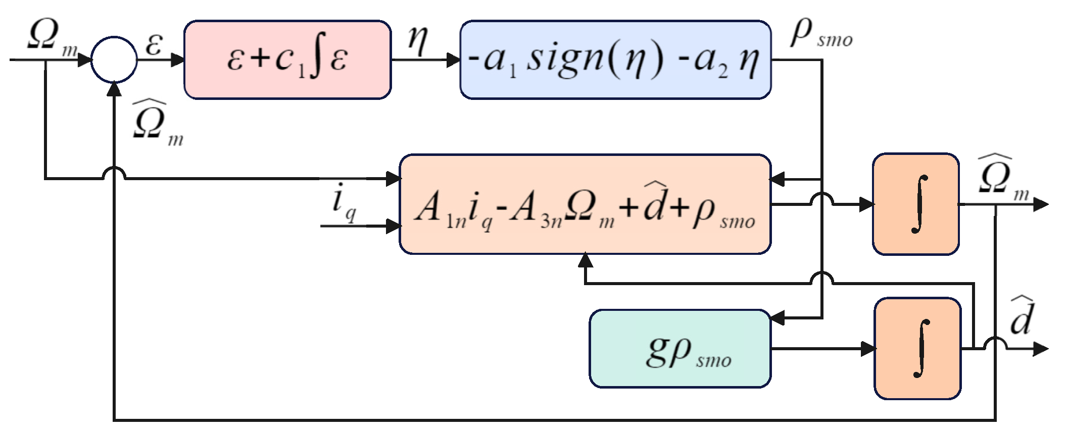
4.4. Sliding-Mode Disturbance Observer Design

In developing an SMC scheme, it is vital to consider the existence of a disturbance d ( t ) , which typically stems from load disturbances and is often presumed to be constant. However, obtaining a constant value for disturbance with precision can be difficult in practical applications. SMDO is introduced to estimate the disturbance from the system output and address this issue.
By employing Equation (16), the PMSM speed system can be represented as follows:
Ω ˙ m = A 1 n i q A 3 n Ω ^ m + d ( t ) d ˙ ( t ) = 0
Therefore, the SMDO model can be designed according to Equation (46).
Ω ^ ˙ m = A 1 n i q A 3 n Ω m + d ^ ( t ) + ρ s m o d ^ ˙ ( t ) = g ρ s m o
where g > 0 denotes the observer gain, ρ s m o denotes the design of the SMC law, d ^ ( t ) denotes the estimated value of d ( t ) , and Ω ^ m denotes the estimated value of Ω m .
Combining Equations (46) and (47), one can obtain
ϵ ˙ s = ϵ d A 3 n ϵ s ρ s m o , ϵ ˙ d = g ρ s m o
The integral sliding manifold is formulated as follows:
η s m d o = ϵ s + c 1 0 t ϵ s d t
where c 1 is a positive constant. The following reaching law is selected:
η ˙ s = a 1 s i g n ( η s ) a 2 η s
where a 1 and a 2 denote positive real values. Deriving the derivative of Equation (49), and then, merging it with Equation (50), results in
ρ s m o = ϵ d A 3 n ϵ s + c 1 ϵ s + a 1 sign ( η s ) + a 2 η s
Without considering the uncertainty term ϵ d , we obtain.
ρ s m o = A 3 n ϵ s + c 1 ϵ s + a 1 sign ( η s ) + a 2 η s
The following Lyapunov function candidate is presented:
V = 1 2 η s 2
whose time derivative can be written as
V ˙ = η s ( c ϵ s A 3 n ϵ s ϵ d ρ s m o ) = η s ( a 1 sign ( η s ) a 2 η s ϵ d ) a 1 | η s | a 2 η s 2 + | η s | | ϵ d |
This condition ensures that d o t V < 0 , when a 1 > | ϵ d | and a 2 > 0 ; this condition ensures that V ˙ < 0 . Consequently, the observer is stable when a 1 and a 2 satisfy the specified requirements.
A block diagram of SMDO is shown in Figure 4.
Figure 5 shows a computational flowchart for implementing the proposed control strategy.

5. Results and Discussion

In this section, simulations and experiments are performed to verify the effectiveness of the proposed VGFOSTSMC method. The specifications of the PMSM used in both the simulation and experimental phases are listed in Table 1. Four different controllers are discussed and compared in various aspects to ensure convincing results for a better understanding.
1.
PI Controller.
2.
CSMC: ρ C S M C = 1 A 1 n Ω ˙ r e f A 3 n Ω d ^ ( t ) + k 1 sign ( η )
3.
Super-twisting sliding-mode control (STSMC) [27]: ρ S T S M C = 1 A 1 n c 1 Ω ˙ r e f c 1 A 3 n Ω c 1 d ^ ( t ) + c 1 ϵ ¨ Ω k 1 | s | 1 2 sign ( η ) k 2 sign ( s )
4.
Proposed VGFOSTSMC: 1 A 1 n ( A 3 n Ω m + d ( t ) Ω ˙ r e f L 1 d D α 1 [ s i g ( ϵ ω ) β ] d t L 2 β ϵ ω 1 β β ϵ ˙ ω M 1 ( η , t ) χ 1 ( η ) 0 t M 2 ( η , t ) χ 2 ( η ) ) , χ 1 ( η ) = | η | 0.5 sign ( η ) + M 3 η , χ 2 ( η ) = χ 1 ( η ) . χ 1 ( η ) = 1 2 sign ( η ) + 2 3 M 3 | η | 0.5 sign ( η ) + M 3 2 η , M 3 > 0

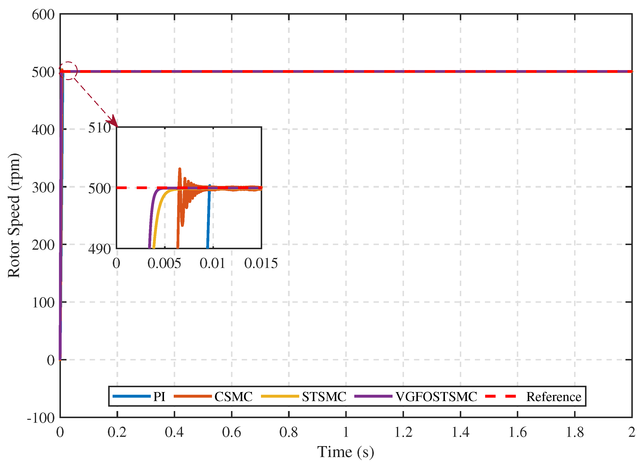
5.1. Simulation Verification

The PMSM is controlled using a vector control scheme with a speed loop and two current loops. Vector control strategy i d r e f = 0 is employed to achieve decoupling. The currents along the d- and q-axes are stabilized using two PI controllers in the current loops. In this study, a speed controller and disturbance observer are introduced to implement the speed loop. Figure 1 illustrates the control structure of the PMSM speed-regulation system based on the VGFOSTSMC. The proposed control method is compared with existing SMC techniques under different scenarios to assess its performance. Subsequently, the effectiveness of the proposed approach is evaluated under a range of conditions.
We carefully tuned the parameters for an optimal control performance to ensure a fair comparison. The parameters for the CSMC are configured as k 1 = 800 . For STSMC, the parameters are set to c 1 = 200 , k 1 = 500 , and k 2 = 800 . The VGFOSTSMC parameters are defined as L 1 = 100 , L 2 = 500 , α = 0.5 , β = 0.5 , q 1 = 0.5 , q 2 = 0.1 , and q 4 = 0.6 . For the SMOD, the parameters are g = 500 , c 1 = 700 , a 1 = 700 , and a 2 = 1000 . In addition, a PI regulator with consistent parameters is applied in the current loop, where the proportional gain k p is set to 10 and the integral gain k i is set to 5.

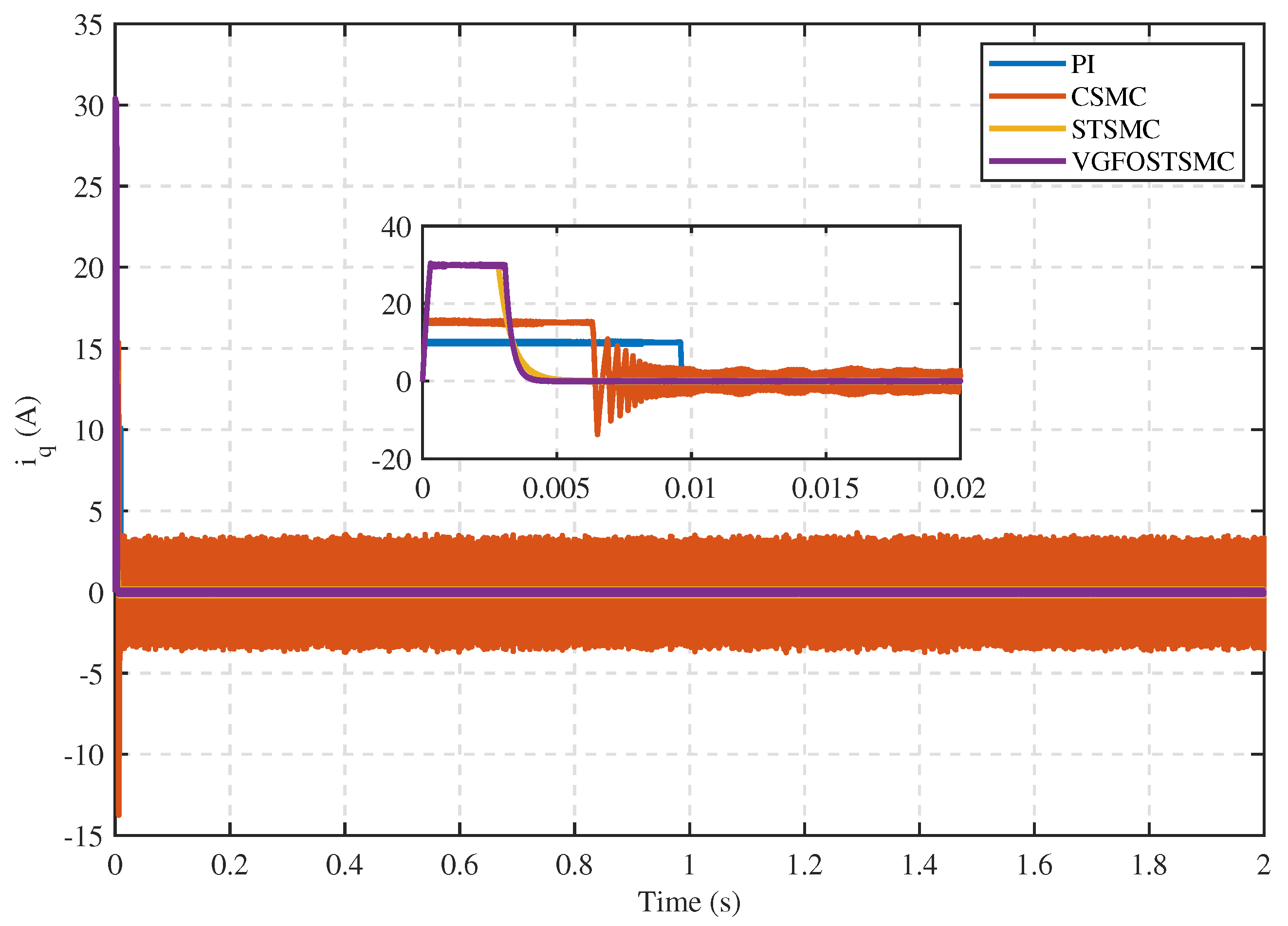
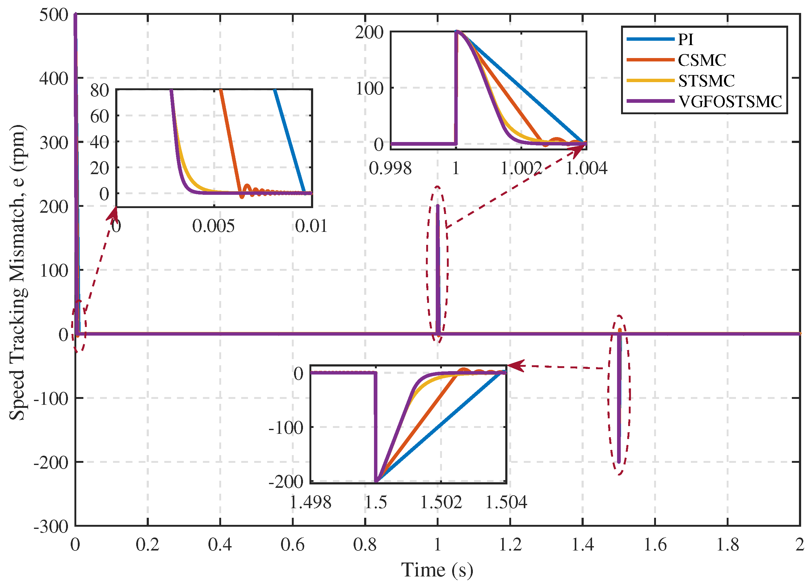
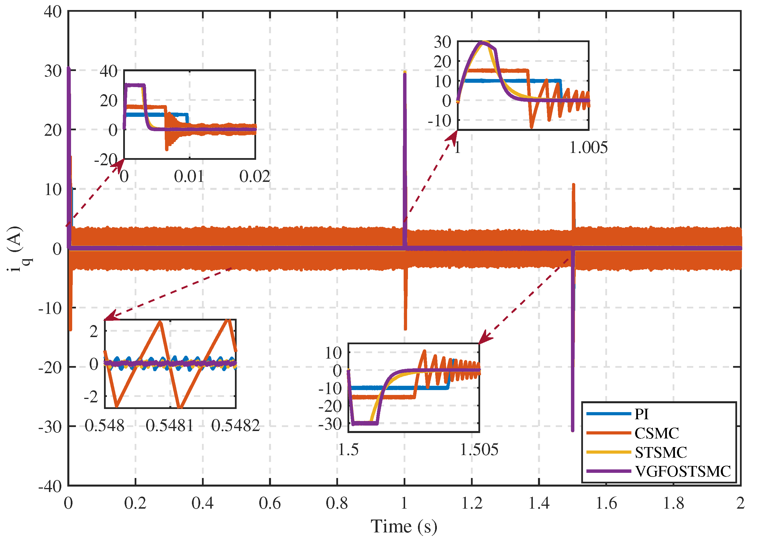
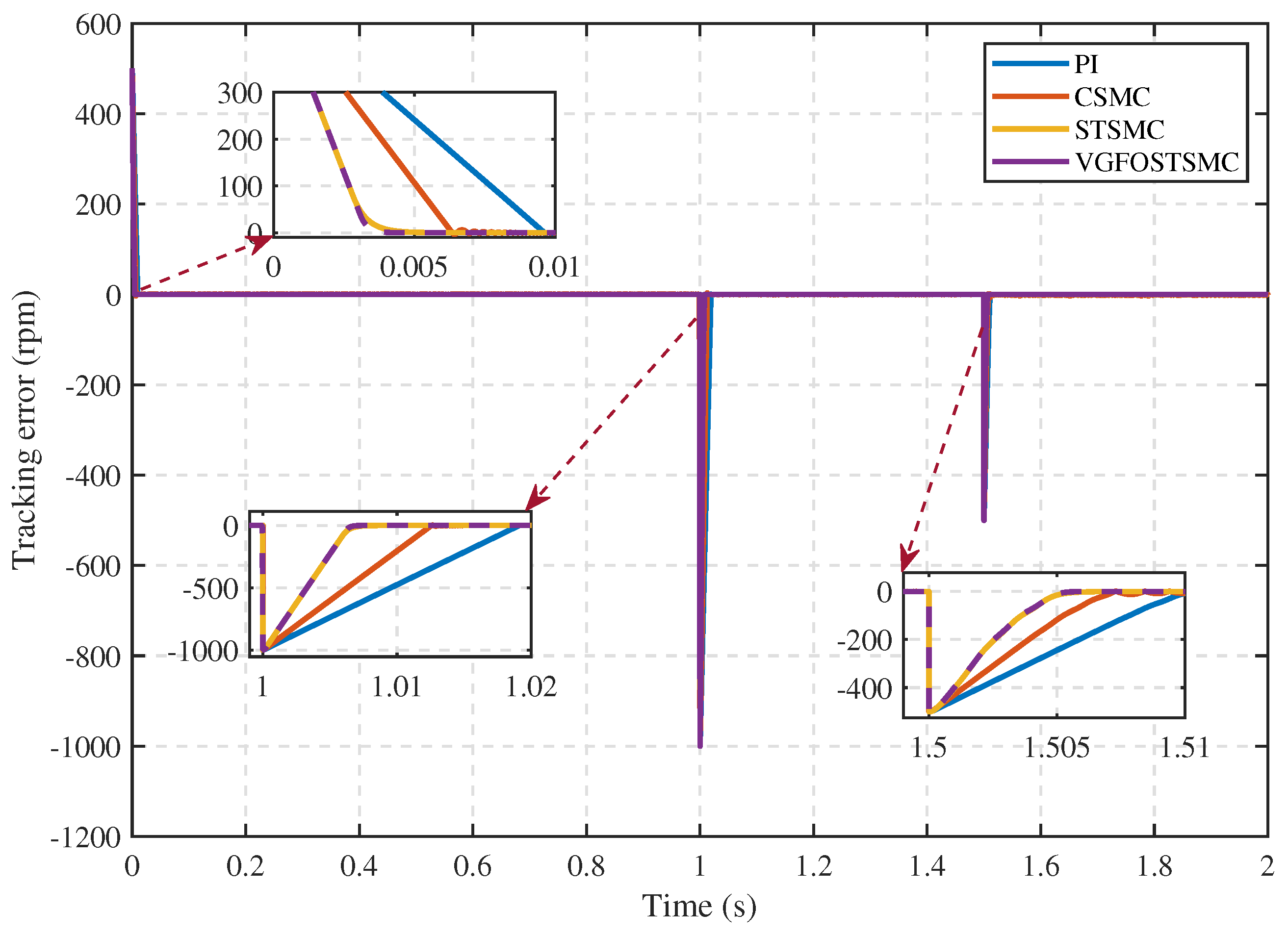
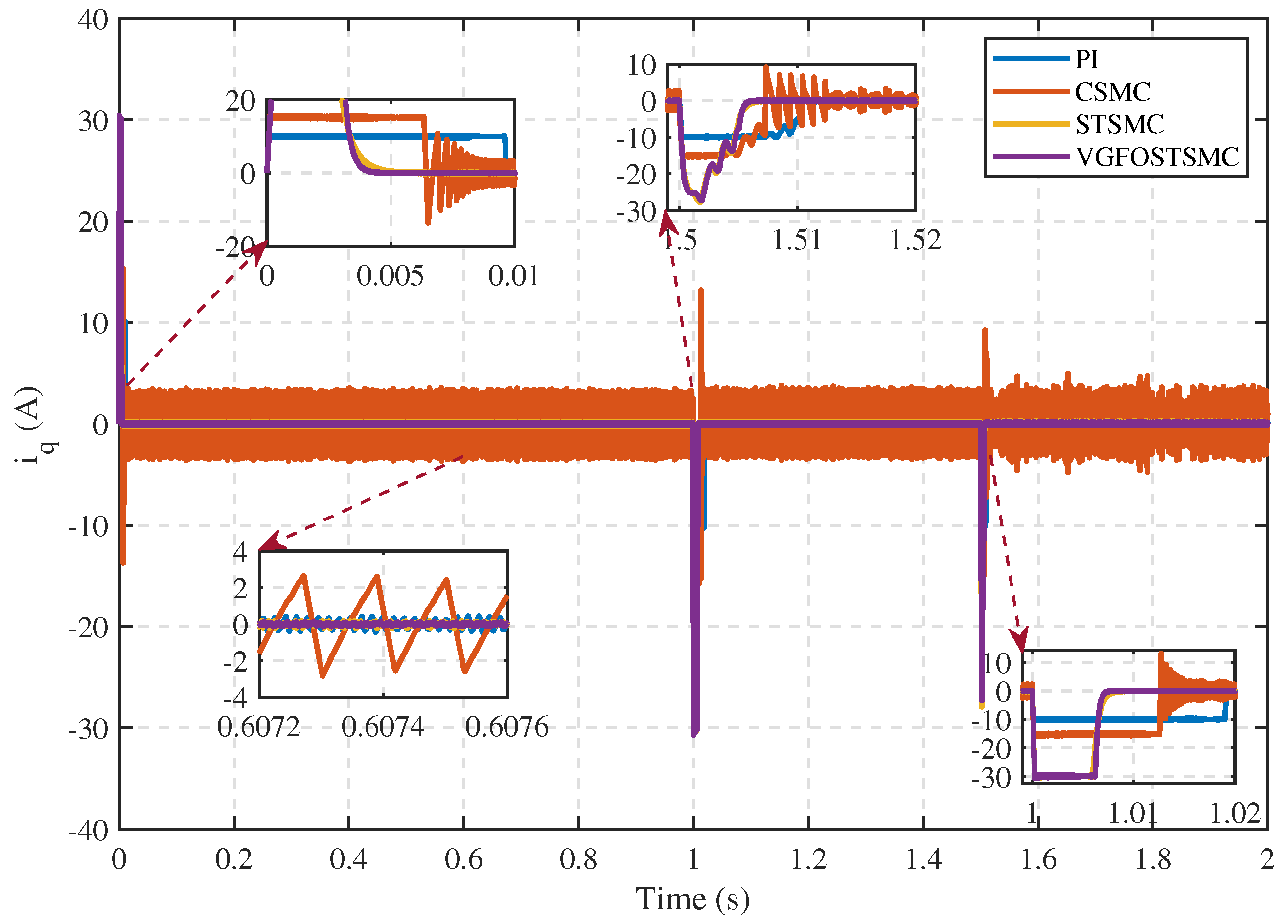
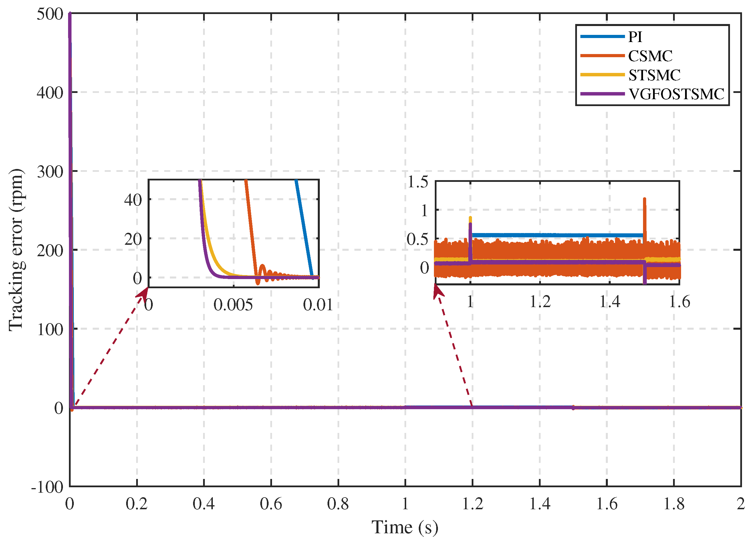
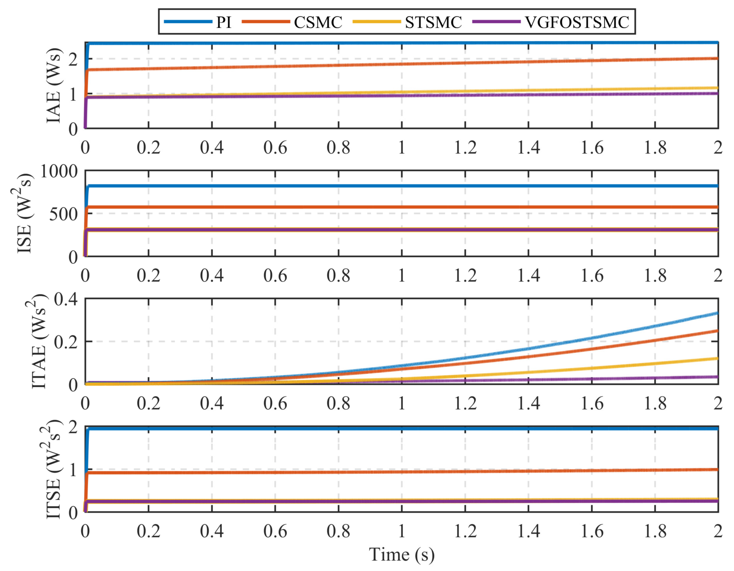
5.1.1. Comparative Performance Analysis of the Proposed Controller with Alternative Control Techniques

To assess the efficacy of the VGFOSTSMC method, we conducted four tests encompassing the diverse operational parameters of the PMSM. A comparative examination employed three distinct control methodologies: PI controller, classical sliding-mode controller (CSMC), and standard STSMC. These analyses aimed to validate the robustness of the proposed approach. The simulations are executed within the MATLAB R2023a framework.
  • Case 1:
The initial test case involved starting the motor at a constant no-load speed of 500 r/min. Figure 6, Figure 7 and Figure 8 illustrate the comparison of the simulation results for speed tracking, error deviation, and control input of the PMSM under standard conditions. This validation process aims to prove the enhanced robustness of the proposed VGFOSTSMC strategy. The analysis in Figure 6 reveals that VGFOSTSMC exhibits a minimal overshoot of 0.0013, outperforming STSMC (0.0080), CSMC (0.6366), and PI control (0.0693). Regarding the response speed, the VGFOSTSMC achieved a settling time of 0.0034, which is notably faster than those of the STSMC (0.0038), CSMC (0.0062), and PI control (0.0094). These findings underscore the ability of VGFOSTSMC to quickly reach a steady state and exhibit reduced oscillation during the initial motor startup, demonstrating superior performance compared to other methodologies. Examining Figure 7 reveals that the VGFOSTSMC controller outperforms the STSMC, CSMC, and PI controls in terms of accuracy, demonstrating its resilience to initial disturbances and capacity for finite-time convergence. The associated current variation, which is indicative of control action adjustments, is shown in Figure 8.
  • Case 2:
A comparative study focused on the dynamic performance of various control strategies to address the frequent speed changes encountered during PMSM operation. In the second scenario, the motor is initiated under no-load conditions and is operated at 500 rpm. At 1 s, a sudden reference speed transition to 700 rpm is introduced, followed by a return to 500 rpm. This specific case aims to validate the efficacy of the proposed VGFOSTSMC in achieving a superior dynamic performance. The simulation results depicted in Figure 9, Figure 10 and Figure 11 highlight the performance of the VGFOSTSMC in comparison with conventional control paradigms, such as PI control, CSMC, and STSMC. Figure 9 illustrates that VGFOSTSMC exhibits a minimal overshoot of 0.82 r/min, notably smaller than PI (1.29 rpm), CSMC (2.70 rpm), and STSMC (0.97 rpm), affirming its superior capability in minimizing overshoot. Furthermore, the VGFOSTSMC demonstrated enhanced responsiveness, achieving a settling time of 0.0075 s, outpacing the PI control (0.0396 s), CSMC (0.097 s), and STSMC (0.092 s), as is evident from the simulation results shown in Figure 9. The accuracy of speed tracking is evaluated through the speed-tracking mismatch illustrated in Figure 10, which indicates VGFOSTSMC’s superior tracking accuracy of VGFOSTSMC compared with other control techniques. Moreover, Figure 11 depicts the rapid adjustment of the current via the VGFOSTSMC towards the desired value, showing its superior agility compared with the PI, CSMC, and STSMC. The findings support the conclusion that VGFOSTSMC outperforms conventional control strategies in terms of minimum overshoot, responsiveness, tracking accuracy, and current adjustment speed, thereby validating its efficacy in addressing the dynamic challenges encountered in PMSM operations.
  • Case 3:
To address the challenges associated with speed changes in PMSM, this study proposes and evaluates a novel approach referred to as VGFOSTSMC. In the third scenario, the motor underwent a series of speed transitions, starting at 500 rpm, reversing direction at 1 s, and ramping to 1000 rpm for 1.5 s. The simulation results, presented in Figure 12, Figure 13 and Figure 14, highlight the efficacy of VGFOSTSMC in mitigating the overshoot in rotational speed compared with alternative SMC methods and PI control. Figure 12 shows that the VGFOSTSMC yields a minimal overshoot in the rotational performance of its PI, CSMC, and STSMC counterparts. Furthermore, VGFOSTSMC exhibits superior response speed with a settling time of 0.01 s, notably faster than PI (0.0487 s), CSMC (0.0275 s), and STSMC (0.0148 s). In terms of the steady-state performance, the VGFOSTSMC demonstrated a steady-state error of 0.029 rpm, which is significantly lower than those of the PI (0.096 rpm), CSMC (0.064 rpm), and STSMC (0.055 rpm). Figure 13 illustrates that the tracking error of VGFOSTSMC is smoother than that of the alternative methods, indicating its robustness in maintaining desired speed trajectories. In addition, Figure 14 shows the ability of the VGFOSTSMC to adjust the motor current swiftly and smoothly to achieve the desired values, distinguishing it from the PI, CSMC, and STSMC strategies. Overall, the proposed VGFOSTSMC approach presents a promising solution for addressing speed variations in PMSMs, offering enhanced performance in terms of overshoot mitigation, response speed, steady-state accuracy, and tracking error reduction compared with conventional control methods.
  • Case 4:
A fourth case scenario is devised to address load disturbances in the operation of PMSMs, in which the motor is initiated at a constant no-load speed of 500 rpm. At 0.49 s, the load suddenly increases to 2 Nm, followed by a further increase to 6 Nm at 1.65 s, then a negative direction decreases to 4 Nm at the same timestamp. The simulation results depicted in Figure 15, Figure 16 and Figure 17 aim to validate the enhanced robustness of the proposed VGFOSTSMC strategy. Figure 15 shows a comparison of the speed-tracking performance. The proposed control method performed better than other SMC methods, achieving a faster reference speed and reduced error. Figure 16 and Figure 17 further demonstrate the effectiveness of VGFOSTSMC, showing precise tracking and smooth control input, distinguishing it from the PI, CSMC, and standard STSMC approaches.
The comprehensive performance comparisons conducted in these simulations reaffirmed the efficacy of the proposed VGFOSTSMC method, demonstrating its superiority in speed regulation for PMSMs compared to the PI controller, traditional CSMC, and STSMC approaches.
In addition, specific error data are collected to quantitatively illustrate the performance of different methods, as outlined in Table 2. The tracking performance of the four techniques is assessed by computing four error indicators: integral square error (ISE), integral absolute error (IAE), integral time squared error (ITSE), and integral time absolute error (ITAE), defined as follows: I S E = 0 e 2 ( t ) d t , I A E = 0 | e ( t ) | d t , I T S E = 0 t e 2 ( t ) d t , and I T A E = 0 t | e ( t ) | d t . Figure 18 depicts ISE, IAE, ITSE, and ITAE for a constant reference speed of 500 rpm. In all the scenarios, the cumulative error for each control method increased with time. Nevertheless, the VGFOSTSMC approach exhibited the most stable error profile and the lowest error rates, outperforming its counterparts. However, the inherent chattering issue in classical SMC results in the highest error compared to other methods, making the STSMC approach the second most effective control method.
A quantitative discussion based on attributes such as steady-state errors, maximum percentage overshoot, and settling time is presented in Table 3 to provide a more precise and comprehensive analysis. This table provides a detailed comparison of the different control techniques and clearly evaluates their respective performances in addressing the specified criteria.

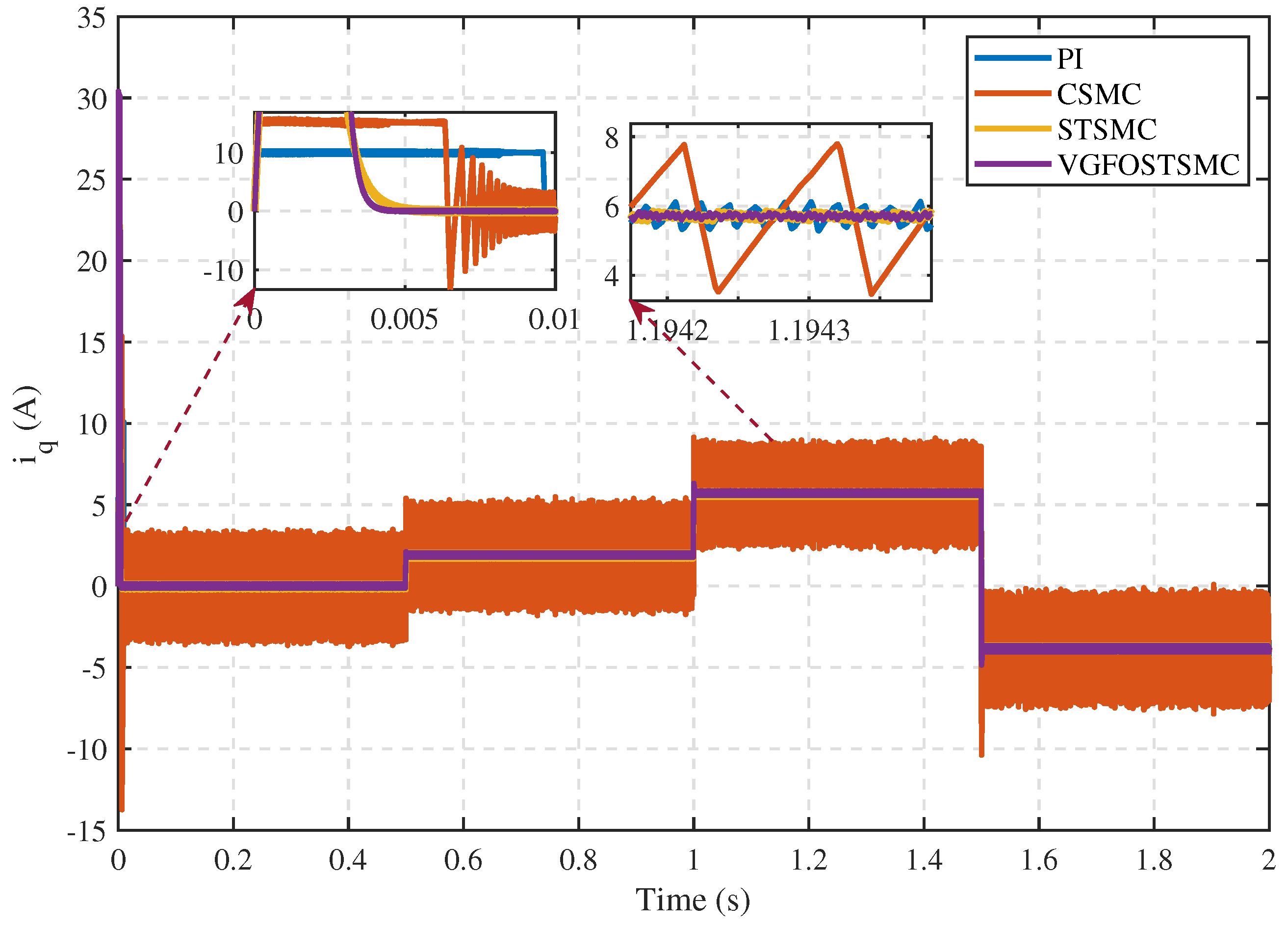
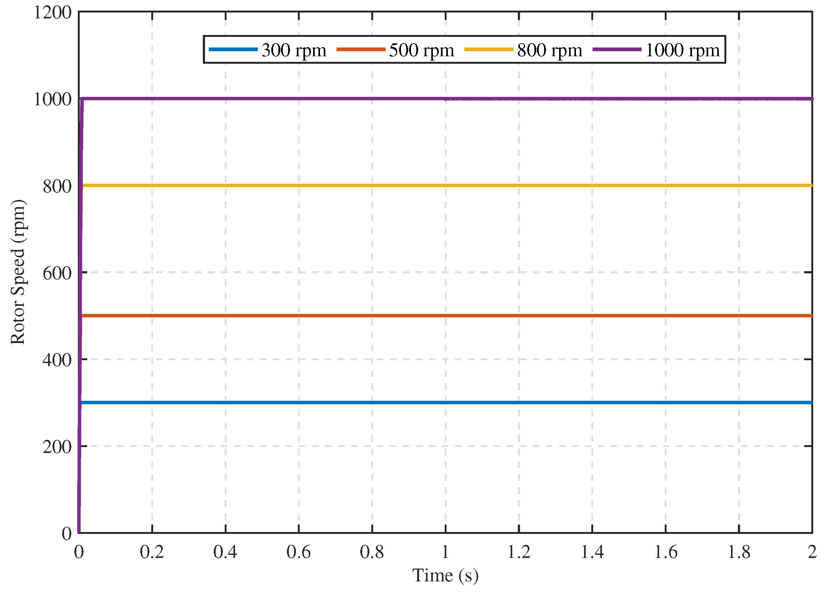
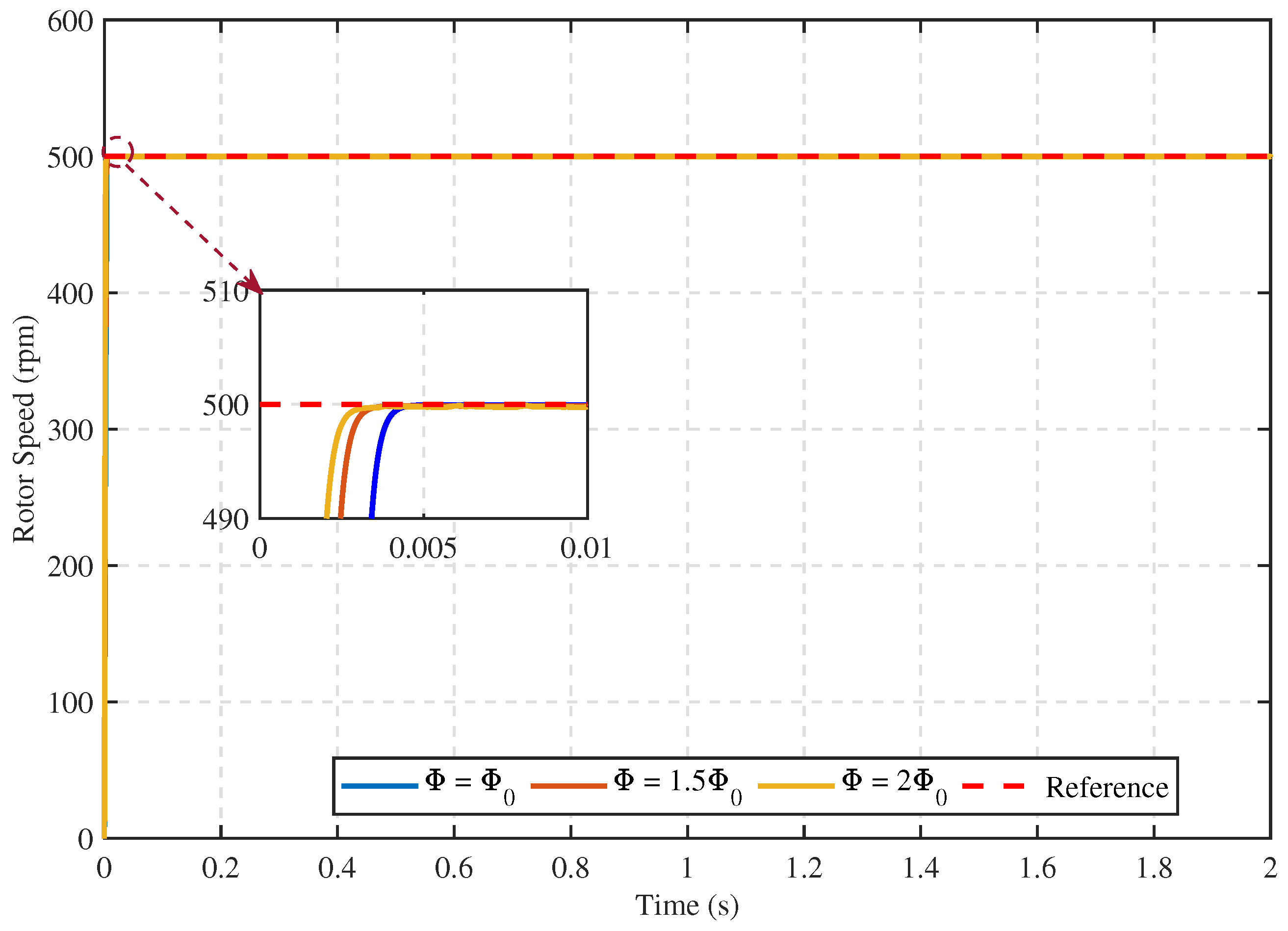
5.1.2. Comparative Performance of the Proposed Speed Controller under Different Conditions

The robustness of the proposed controller is thoroughly assessed through a series of simulations to examine its performance under diverse external and parametric conditions. Figure 19 shows the excellent tracking performance of the proposed VGFOSTSMC controller when subjected to a wide range of reference speeds (300–1000 rpm). The results showed minimal overshoot and shorter settling time, indicating superior tracking capabilities with reduced oscillations. Notably, the controller effectively managed external disturbances such as sudden changes in the reference speed, demonstrating its robustness and adaptability. Figure 20 illustrates the controller’s exceptional tracking performance under a challenge in which the load torque varies from 2 Nm to 8 Nm while maintaining a desired speed of 500 rpm. Despite significant fluctuations in the load torque, the controller precisely tracked the reference speed with only a slight decrease in the observed speed of 0.7%. This demonstrates the robustness and the ability of the controller to reject external disturbances, thereby ensuring that the desired speed is maintained. Figure 21 illustrates the adaptability of the VGFOSTSMC scheme to changes in the system inertia, demonstrating its robustness in managing dynamic changes within the system. The system inertia is initially set to J 0 = 0.8 × 10⁻³ kg.m2. When the system inertia changes, the proposed control approach demonstrates excellent adaptability, thereby confirming its ability to handle dynamic variations. The proposed control scheme demonstrated exceptional tracking performance, consistently achieving precise and rapid reference-speed tracking across various system inertia variations. Notably, the settling time remains impressively low (consistently below 0.1 s for all system inertia values, demonstrating the controller’s remarkable adaptability and robustness. Figure 22 further demonstrates the robustness of the proposed control law, showing tracking performance under flux-linkage variations. Despite the rotor flux value changes, the proposed VGFOSTSMC scheme maintained a stable and precise tracking performance, exhibiting robustness to these variations. Notably, the settling time remains consistent and unaffected by changes in the system inertia, thereby highlighting the adaptability and ability of the scheme to handle dynamic changes in the system.
The VGFOSTSMC controller demonstrated resilience in the management of internal parameter variations and external disturbances. The simulation results underscored its effectiveness as a robust anti-disturbance controller for controlling PMSM speed, surpassing the performance of conventional SMC controllers. The consistent and reliable performance of the proposed control paradigm reaffirms its potential for practical implementation in PMSM speed-regulation applications.

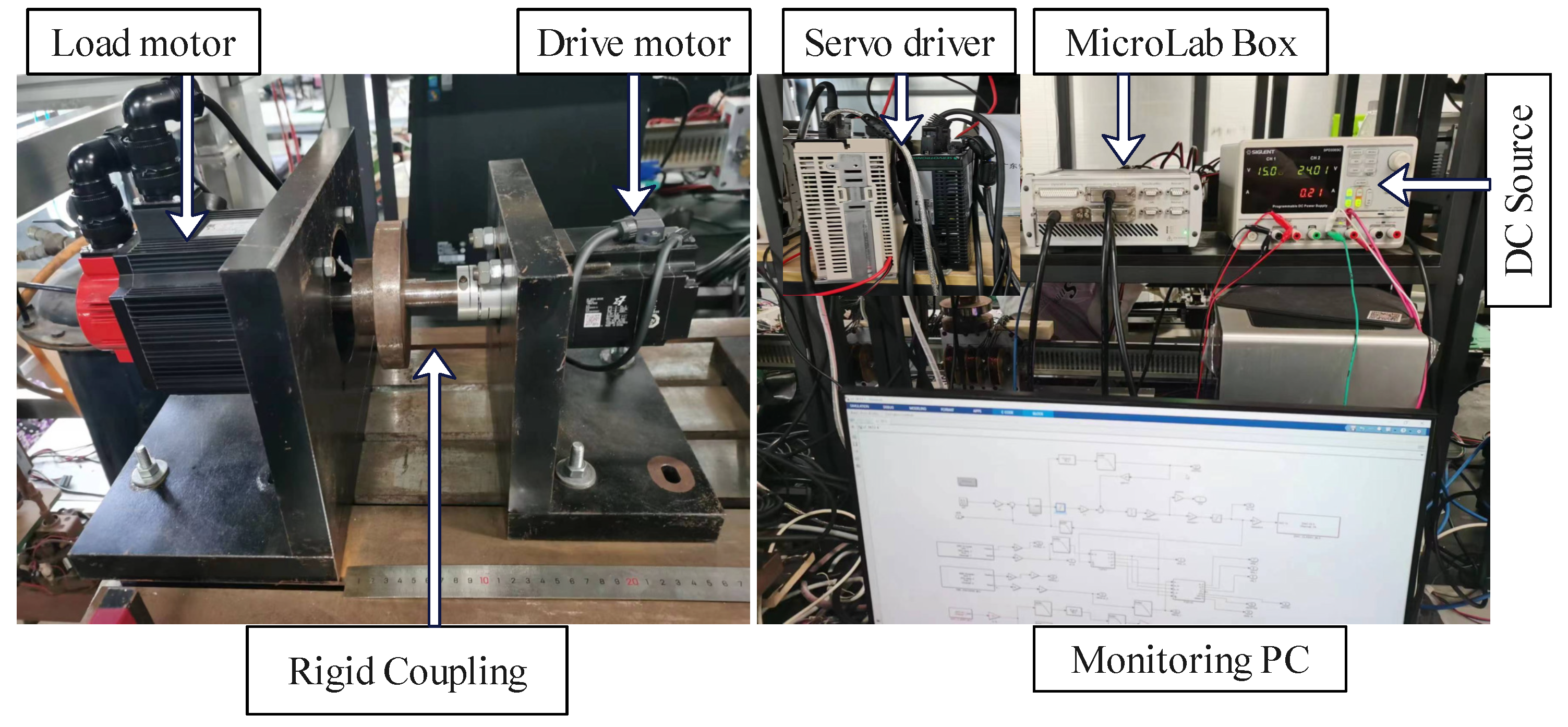
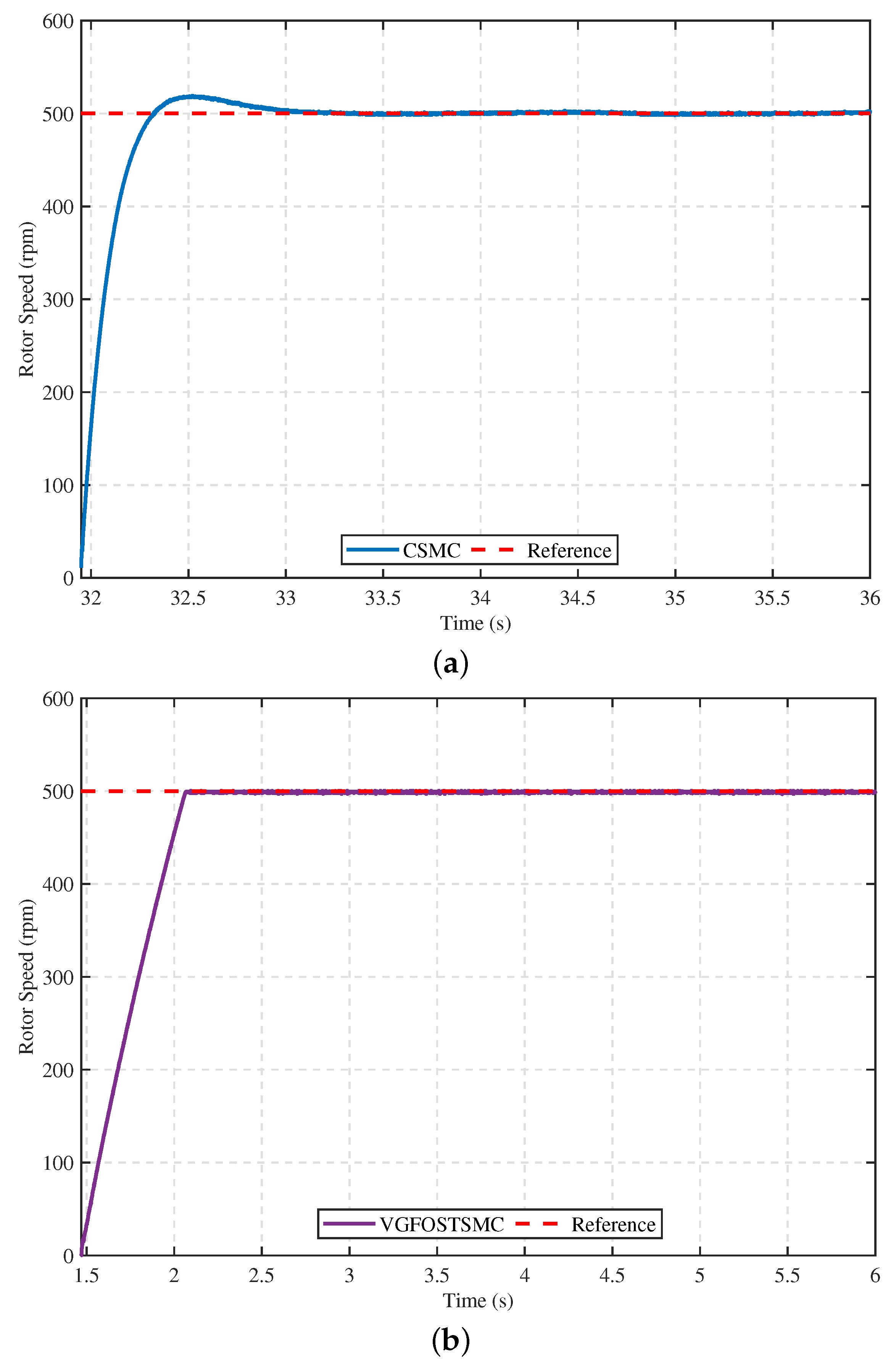
5.2. Experimental Validation

This section aims to provide experimental verification to further validate the effectiveness of the proposed method on a comprehensive motor speed regulation and loading platform. The alignment of the motor parameters used in the experimental platform with those employed in the simulation verification is confirmed in Table 1. In addition, Figure 23 visually depicts the experimental setup, providing insight into the testing environment and equipment arrangement.
The experimental setup primarily consisted of power distribution lines, a monitoring PC, a DC source, servo drivers, rigid couplings, a drive motor, a load motor, and a Microlab Box dSpace. Before conducting the motor speed control experiment, the electronic version of the proposed control method is uploaded to Microlab Box-dSpace. All the platform parameters are carefully checked to ensure normal functioning. Real-time experimental data, collected and analyzed using a monitoring PC, confirm the feasibility and effectiveness of the proposed approach. The experimental results provide practical evidence for the performance of the proposed VGFOSTSMC controller and its potential for successful implementation in real-world applications.
The experimental verification involves several scenarios to assess the motor performance. Initially, the motor is smoothly started and maintained at a speed of 500 rpm for 5 s without any external load applied. In the second scenario, the motor operates at 500 r/min for 2.5 s. However, after this period, a sudden load disturbance of approximately 10% of the rated torque of the motor is introduced for 1 s before removal. In the third case, the engine is operated at 500 r/min for 1.5 s. Subsequently, the speed is increased to 700 rpm for 2 s and then returned to 500 rpm for an additional 1.5 s. The experimental setup is employed to examine and compare the CSMC and the proposed VGFOSTSMC methods. The speed curves are carefully documented and are illustrated in Figure 24, Figure 25 and Figure 26.
Distinct differences are observed by analyzing the speed-tracking performance of the CSMC and VGFOSTSMC based on the experimental results depicted in Figure 24. Specifically, regarding settling time, CSMC had a value of 0.8453, whereas VGFOSTSMC had a notably lower value of 0.5083, suggesting faster settling for the latter. Additionally, when comparing the overshoot percentages, the CSMC exhibits a higher value of 4.1319% compared to VGFOSTSMC’s significantly lower value of 0.4538% indicating better control over overshooting tendencies with the VGFOSTSMC. Furthermore, by examining the steady-state error, the CSMC registers a higher value of 0.4545%, in contrast to VGFOSTSMC’s substantially reduced value of 0.0383%, suggesting improved precision and accuracy in maintaining the desired speed of VGFOSTSMC.
According to the findings from the load experiments illustrated in Figure 25, the conventional SMC system displayed considerable speed fluctuations, averaging 14.51% during load changes. In contrast to the CSMC method, the VGFOSTSMC system demonstrated significantly reduced speed fluctuations, measuring only 5.84%. This indicates that the VGFOSTSMC exhibits a superior system response speed and higher resilience to load disturbances.
The experimental results presented in Figure 26 reveal significant differences in performance between the conventional sliding-mode controller (CSMC) and the variable-gain fractional-order super-twisting sliding-mode controller (VGFOSTSMC). Notably, the VGFOSTSMC method achieved a substantially shorter settling time of 0.5071 s compared with 4.0550 s for the CSMC. Furthermore, the VGFOSTSMC method exhibited a lower overshoot of 0.5314 and steady-state error of 0.4042, whereas the CSMC method had a higher overshoot of 5.6587 and steady-state error of 0.4495. These results demonstrate the superior effectiveness of the VGFOSTSMC approach in reducing settling time, overshoot, and steady-state error in a permanent magnet synchronous motor (PMSM) system when responding to changes in reference speed. This highlights the potential of the VGFOSTSMC method in enhancing the stability, responsiveness, and overall performance of the system.
The experimental findings are in close agreement with the simulated results, validating the reliability of the proposed scheme. The simulation and experimental data demonstrate the outstanding speed-tracking performance of the algorithm, marked by negligible errors and robustness against load disturbances. This confirms the efficacy of the algorithm in regulating PMSM system speeds and offers a promising solution for efficient speed control in practical applications, thereby showcasing its potential for real-world applications.

6. Conclusions

This paper presents a novel approach for controlling the speed of permanent magnet synchronous motor (PMSM) drive systems by leveraging a novel variable-gain fractional-order super-twisting (VGFOST) controller. The sliding-mode (SM) controller embedded within the sliding-mode algorithm (STA) features a unique sliding surface and an adaptive gain structure. In addition, a sliding-mode disturbance observer (SMDO) is developed to estimate and mitigate system disturbances. The integration of VGFOST and SMDO forms a robust composite control strategy, significantly enhancing the system’s ability to reject disturbances and maintain optimal performance. Theoretical analyses are performed to evaluate the stability and assess the accuracy of the controller and SMDO. These analyses highlight the benefits of the proposed composite-control method. The simulation and experimental results confirm the theoretical conclusions, illustrating that the proposed method provides numerous benefits including high precision, uncertainty resilience, and minimal chattering amplitude. These characteristics guarantee the exceptional performance of PMSM drive systems. Moreover, thorough simulations and experimental outcomes, coupled with quantitative analyses, offer substantiating evidence for the effectiveness of the proposed algorithm when implemented in PMSM drive systems.
Future studies will focus on optimizing the parameter-tuning process and implementing adaptive control strategies to further enhance the performance and robustness of the proposed controller in real-world PMSM drive applications.

Author Contributions

Conceptualization, A.U., J.P. and S.U.; Methodology, A.U., J.P., S.U. and Z.Z.; Software, A.U. and S.U.; Validation, S.U. and Z.Z.; Formal analysis, S.U. and Z.Z.; Resources, A.U. and J.P.; Writing—original draft, A.U., J.P. and S.U.; Writing—review & editing, A.U. and S.U. All authors have read and agreed to the published version of the manuscript.

Funding

This work is supported in part by the National Natural Science Foundation of China (52277060) and in part by the General Research Project of Shenzhen Science and Technology Plan (JCYJ20220818100000001, SGDX20230116110009018).

Data Availability Statement

The data presented in this study are available on request from the corresponding author.

Conflicts of Interest

The authors declare no conflicts of interest.

References

  1. Vlachou, V.I.; Sakkas, G.K.; Xintaropoulos, F.P.; Pechlivanidou, M.S.C.; Kefalas, T.D.; Tsili, M.A.; Kladas, A.G. Overview on Permanent Magnet Motor Trends and Developments. Energies 2024, 17, 538. [Google Scholar] [CrossRef]
  2. Majout, B.; Bossoufi, B.; Karim, M.; Skruch, P.; Mobayen, S.; El Mourabit, Y.; Laggoun, Z.E.Z. Artificial neural network-based direct power control to enhance the performance of a PMSG-wind energy conversion system under real wind speed and parameter uncertainties: An experimental validation. Energy Rep. 2024, 11, 4356–4378. [Google Scholar] [CrossRef]
  3. Zhu, L.; Zhang, G.; Jing, R.; Bi, G.; Xiang, R.; Wang, G.; Xu, D. Nonlinear active disturbance rejection control strategy for permanent magnet synchronous motor drives. IEEE Trans. Energy Convers. 2022, 37, 2119–2129. [Google Scholar] [CrossRef]
  4. Zheng, Y.; Cao, Z.; Wang, S.; Man, Z.; Chuei, R. Extreme learning machine-based field-oriented feedback linearization speed control of permanent magnetic synchronous motors. Neural Comput. Appl. 2022, 34, 5267–5282. [Google Scholar] [CrossRef]
  5. Yuan, X.; Chen, J.; Liu, W.; Lee, C.H. A linear control approach to design digital speed control system for PMSMs. IEEE Trans. Power Electron. 2022, 37, 8596–8610. [Google Scholar] [CrossRef]
  6. Zhang, X.; Zhang, C. Model predictive control for open winding PMSM considering dead-zone effect. IEEE J. Emerg. Sel. Top. Power Electron. 2022, 11, 874–885. [Google Scholar] [CrossRef]
  7. Liu, Z.; Huang, X.; Hu, Q.; Li, Z.; Jiang, Z.; Yu, Y.; Chen, Z. A modified deadbeat predictive current control for improving dynamic performance of PMSM. IEEE Trans. Power Electron. 2022, 37, 14173–14185. [Google Scholar] [CrossRef]
  8. Qu, L.; Qiao, W.; Qu, L. Active-disturbance-rejection-based sliding-mode current control for permanent-magnet synchronous motors. IEEE Trans. Power Electron. 2020, 36, 751–760. [Google Scholar] [CrossRef]
  9. Dai, C.; Guo, T.; Yang, J.; Li, S. A disturbance observer-based current-constrained controller for speed regulation of PMSM systems subject to unmatched disturbances. IEEE Trans. Ind. Electron. 2020, 68, 767–775. [Google Scholar] [CrossRef]
  10. Senhaji, A.; Abdelouhab, M.; Attar, A.; Bouchnaif, J. Backstepping control of a permanent magnet synchronous motor. Mater. Today Proc. 2023, 72, 3730–3737. [Google Scholar] [CrossRef]
  11. Regaya, C.B.; Farhani, F.; Zaafouri, A.; Chaari, A. A novel adaptive control method for induction motor based on Backstepping approach using dSpace DS 1104 control board. Mech. Syst. Signal Process. 2018, 100, 466–481. [Google Scholar] [CrossRef]
  12. Ullah, S.; Mehmood, A.; Khan, Q.; Rehman, S.; Iqbal, J. Robust integral sliding mode control design for stability enhancement of under-actuated quadcopter. Int. J. Control Autom. Syst. 2020, 18, 1671–1678. [Google Scholar] [CrossRef]
  13. Ullah, S.; Khan, Q.; Zaidi, M.M.; Hua, L.G. Neuro-adaptive non-singular terminal sliding mode control for distributed fixed-time synchronization of higher-order uncertain multi-agent nonlinear systems. Inf. Sci. 2024, 659, 120087. [Google Scholar] [CrossRef]
  14. Sreejeth, M.; Singh, M. Improved ANFIS based MRAC observer for sensorless control of PMSM. J. Intell. Fuzzy Syst. 2022, 42, 1061–1073. [Google Scholar]
  15. Ullah, S.; Khan, Q.; Mehmood, A. Neuro-adaptive fixed-time non-singular fast terminal sliding mode control design for a class of under-actuated nonlinear systems. Int. J. Control 2023, 96, 1529–1542. [Google Scholar] [CrossRef]
  16. Mohd Zaihidee, F.; Mekhilef, S.; Mubin, M. Robust speed control of PMSM using sliding mode control (SMC)—A review. Energies 2019, 12, 1669. [Google Scholar] [CrossRef]
  17. Bouguenna, I.F.; Tahour, A.; Kennel, R.; Abdelrahem, M. Multiple-vector model predictive control with fuzzy logic for PMSM electric drive systems. Energies 2021, 14, 1727. [Google Scholar] [CrossRef]
  18. He, H.; Gao, J.; Wang, Q.; Wang, J.; Zhai, H. Improved Sliding Mode Observer for the Sensorless Control of Permanent Magnet Synchronous Motor. J. Electr. Eng. Technol. 2024, 1–13. [Google Scholar] [CrossRef]
  19. Regaya, C.B.; Farhani, F.; Zaafouri, A.; Chaari, A. An adaptive sliding-mode speed observer for induction motor under backstepping control. ICIC Express Lett. 2017, 11, 763–771. [Google Scholar]
  20. Mishra, R.N.; Mohanty, K.B. Development and implementation of induction motor drive using sliding-mode based simplified neuro-fuzzy control. Eng. Appl. Artif. Intell. 2020, 91, 103593. [Google Scholar] [CrossRef]
  21. Zhang, W.; Kong, J. A novel fast and chattering-free speed control method for PMSM motor drive based on sliding mode control. Int. J. Dyn. Control 2024, 1–7. [Google Scholar] [CrossRef]
  22. Guo, J. The load frequency control by adaptive high order sliding mode control strategy. IEEE Access 2022, 10, 25392–25399. [Google Scholar] [CrossRef]
  23. Liu, Y.C.; Laghrouche, S.; Depernet, D.; Djerdir, A.; Cirrincione, M. Disturbance-observer-based complementary sliding-mode speed control for PMSM drives: A super-twisting sliding-mode observer-based approach. IEEE J. Emerg. Sel. Top. Power Electron. 2020, 9, 5416–5428. [Google Scholar] [CrossRef]
  24. Marcos-Andrade, D.; Beltran-Carbajal, F.; Rivas-Cambero, I.; Yañez-Badillo, H.; Favela-Contreras, A.; Rosas-Caro, J.C. Sliding Mode Speed Control in Synchronous Motors for Agriculture Machinery: A Chattering Suppression Approach. Agriculture 2024, 14, 737. [Google Scholar] [CrossRef]
  25. Hernandez-Gonzalez, M.; Alanis, A.; Rios, J.; Hernadez-Vargas, E. Exponential sliding mode controller for tracking trajectory of nonlinear systems. Trans. Inst. Meas. Control 2024, 46, 1058–1068. [Google Scholar] [CrossRef]
  26. Ge, Y.; Yang, L.; Ma, X. Adaptive sliding mode control based on a combined state/disturbance observer for the disturbance rejection control of PMSM. Electr. Eng. 2020, 102, 1863–1879. [Google Scholar] [CrossRef]
  27. Hu, M.; Ahn, H.; Chung, Y.; You, K. Speed Regulation for PMSM with Super-Twisting Sliding-Mode Controller via Disturbance Observer. Mathematics 2023, 11, 1618. [Google Scholar] [CrossRef]
  28. Karami-Mollaee, A.; Barambones, O. Higher Order Sliding Mode Control of MIMO Induction Motors: A New Adaptive Approach. Mathematics 2023, 11, 4558. [Google Scholar] [CrossRef]
  29. Zhang, Y.; Jin, J.; Huang, L. Model-free predictive current control of PMSM drives based on extended state observer using ultralocal model. IEEE Trans. Ind. Electron. 2020, 68, 993–1003. [Google Scholar] [CrossRef]
  30. El-Sousy, F.F.; Amin, M.M.; Soliman, A.S.; Mohammed, O.A. Optimal Adaptive Ultra-Local Model-Free Control Based-Extended State Observer for PMSM Driven Single-Axis Servo Mechanism System. IEEE Trans. Ind. Appl. 2024, 1–8. [Google Scholar] [CrossRef]
  31. Long, Y.; Wang, Y.M.; Yao, C.; Song, E.Z.; Dong, Q. Adaptive Second-order Sliding Mode Control of Electrical Throttles Based on Online Zero-crossing Checking. Int. J. Control Autom. Syst. 2024, 22, 489–502. [Google Scholar] [CrossRef]
  32. Levant, A. Sliding order and sliding accuracy in sliding mode control. Int. J. Control 1993, 58, 1247–1263. [Google Scholar] [CrossRef]
  33. Levant, A. Homogeneity approach to high-order sliding mode design. Automatica 2005, 41, 823–830. [Google Scholar] [CrossRef]
  34. Gonzalez, T.; Moreno, J.A.; Fridman, L. Variable gain super-twisting sliding mode control. IEEE Trans. Autom. Control 2011, 57, 2100–2105. [Google Scholar] [CrossRef]
  35. Kürkçü, B.; Kasnakoğlu, C.; Efe, M.Ö. Disturbance/uncertainty estimator based integral sliding-mode control. IEEE Trans. Autom. Control 2018, 63, 3940–3947. [Google Scholar] [CrossRef]
  36. Eray, O.; Tokat, S. The design of a fractional-order sliding mode controller with a time-varying sliding surface. Trans. Inst. Meas. Control 2020, 42, 3196–3215. [Google Scholar] [CrossRef]
  37. Sun, G.; Wu, L.; Kuang, Z.; Ma, Z.; Liu, J. Practical tracking control of linear motor via fractional-order sliding mode. Automatica 2018, 94, 221–235. [Google Scholar] [CrossRef]
  38. Zaihidee, F.M.; Mekhilef, S.; Mubin, M. Application of fractional order sliding mode control for speed control of permanent magnet synchronous motor. IEEE Access 2019, 7, 101765–101774. [Google Scholar] [CrossRef]
  39. Xu, S.; Sun, G.; Ma, Z.; Li, X. Fractional-order fuzzy sliding mode control for the deployment of tethered satellite system under input saturation. IEEE Trans. Aerosp. Electron. Syst. 2018, 55, 747–756. [Google Scholar] [CrossRef]
  40. Wang, Y.; Chen, J.; Yan, F.; Zhu, K.; Chen, B. Adaptive super-twisting fractional-order nonsingular terminal sliding mode control of cable-driven manipulators. ISA Trans. 2019, 86, 163–180. [Google Scholar] [CrossRef]
  41. Daftardar-Gejji, V. Fractional Calculus and Fractional Differential Equations; Springer: Berlin/Heidelberg, Germany, 2019. [Google Scholar]
  42. Dávila, A.; Moreno, J.A.; Fridman, L. Variable gains super-twisting algorithm: A Lyapunov based design. In Proceedings of the 2010 American Control Conference, Baltimore, MD, USA, 30 June–2 July 2010; pp. 968–973. [Google Scholar]
  43. Utkin, V.I. Sliding Modes in Optimization and Control Problems; Springer: New York, NY, USA, 1992. [Google Scholar]
  44. Utkin, V.; Poznyak, A.; Orlov, Y.V.; Polyakov, A. Road Map for Sliding Mode Control Design; Springer: Berlin/Heidelberg, Germany, 2020. [Google Scholar]
  45. Utkin, V.; Poznyak, A.; Orlov, Y.; Polyakov, A. Conventional and high order sliding mode control. J. Frankl. Inst. 2020, 357, 10244–10261. [Google Scholar] [CrossRef]
  46. Boeren, F.; Bareja, A.; Kok, T.; Oomen, T. Frequency-domain ILC approach for repeating and varying tasks: With application to semiconductor bonding equipment. IEEE/ASME Trans. Mechatron. 2016, 21, 2716–2727. [Google Scholar] [CrossRef]
  47. Zheng, M.; Wang, C.; Sun, L.; Tomizuka, M. Design of arbitrary-order robust iterative learning control based on robust control theory. Mechatronics 2017, 47, 67–76. [Google Scholar] [CrossRef]
Figure 1. Progress made in sliding-mode control.
Fractalfract 08 00368 g001
Figure 2. Representation of the PMSM system architecture.
Fractalfract 08 00368 g002
Figure 3. Block diagram of VGFOSTSMC.
Fractalfract 08 00368 g003
Figure 4. Block diagram of SMDO.
Fractalfract 08 00368 g004
Figure 5. Computational flowchart of the proposed control technique.
Fractalfract 08 00368 g005
Figure 6. Comparative analysis of speed-tracking performance of VGFOSTSMC alongside other SMC and PI controllers under nominal conditions.
Fractalfract 08 00368 g006
Figure 7. Comparative analysis of speed-tracking mismatch of VGFOSTSMC alongside other SMC and PI controllers under nominal conditions.
Fractalfract 08 00368 g007
Figure 8. Comparative analysis of control action of VGFOSTSMC alongside other SMC and PI controllers under nominal conditions.
Fractalfract 08 00368 g008
Figure 9. Comparative assessment of speed-tracking performance between VGFOSTSMC, other SMC, and PI controllers for upward and downward reference speed scenarios.
Fractalfract 08 00368 g009
Figure 10. Comparative assessment of speed-tracking mismatch between VGFOSTSMC, other SMC, and PI controllers for upward and downward reference speed scenarios.
Fractalfract 08 00368 g010
Figure 11. Comparative assessment of control input performance between VGFOSTSMC, other SMC, and PI controllers for upward and downward reference speed scenarios.
Fractalfract 08 00368 g011
Figure 12. Comparative analysis of speed-tracking performance between VGFOSTSMC and other SMC controllers, along with PI, during speed reversal.
Fractalfract 08 00368 g012
Figure 13. Comparative analysis of speed-tracking error between VGFOSTSMC and other SMC controllers, along with PI, during speed reversal.
Fractalfract 08 00368 g013
Figure 14. Comparative analysis of control input between VGFOSTSMC and other SMC controllers, along with PI, during speed reversal.
Fractalfract 08 00368 g014
Figure 15. Comparative evaluation of speed-tracking performance between VGFOSTSMC and other SMC controllers, along with PI, during load change.
Fractalfract 08 00368 g015
Figure 16. Comparative evaluation of speed-tracking mismatch between VGFOSTSMC and other SMC controllers, along with PI, during load change.
Fractalfract 08 00368 g016
Figure 17. Comparative evaluation of control input between VGFOSTSMC and other SMC controllers, along with PI, during load change.
Fractalfract 08 00368 g017
Figure 18. Performance indices.
Fractalfract 08 00368 g018
Figure 19. Speed response of VGFOSTSMC under variance reference speeds.
Fractalfract 08 00368 g019
Figure 20. Speed tracking of VGFOSTSMC under variance load torques.
Fractalfract 08 00368 g020
Figure 21. Speed tracking of VGFOSTSMC under varying inertia.
Fractalfract 08 00368 g021
Figure 22. Speed tracking of VGFOSTSMC under varying flux linkage.
Fractalfract 08 00368 g022
Figure 23. Experimental setup.
Fractalfract 08 00368 g023
Figure 24. Speed-tracking comparison under nominal conditions using (a) CSMC and (b) VGFOSTSMC.
Fractalfract 08 00368 g024
Figure 25. Comparison of speed tracking during loading and unloading using controllers (a) CSMC and (b) VGFOSTSMC.
Fractalfract 08 00368 g025
Figure 26. Comparison of speed tracking during speed-up and speed-down experiments using (a) CSMC and (b) VGFOSTSMC.
Fractalfract 08 00368 g026
Table 1. Quantitative list of parameters of PMSM.
ParameterSymbolValue
Flux Φ m 0.181 Wb
System inertiaJ0.00079 kgm2
Number of pole pairs p n 3
Viscous friction coefficientB0.00001 Nms/rad
dq-axis inductances L d , L q 11.58 mH
Stator resistance R s 3.45 Ω
Rated speed ω m 3001 rpm
Rated powerP1.21 kW
Table 2. Quantitative assessment of performance index errors.
IndexPICSMCSTSMCVGFOSTSMC
ISE819.5548.5310.6310.1
IAE2.4641.9481.1641.002
ITSE1.940.92110.28090.2553
ITAE0.034580.32910.24940.1207
Table 3. Error data.
SpecificationsPICSMCSTSMCVGFOSTSMC
Steady-state error0.01020.19830.11430.0614
Maximum overshoot [%]0.06930.66660.00540.0041
Settling time (s)0.00940.00620.00380.0034
Disclaimer/Publisher’s Note: The statements, opinions and data contained in all publications are solely those of the individual author(s) and contributor(s) and not of MDPI and/or the editor(s). MDPI and/or the editor(s) disclaim responsibility for any injury to people or property resulting from any ideas, methods, instructions or products referred to in the content.

