Abstract
A linear position sensor for pneumatic actuators is presented. Position of the piston rod made of ferromagnetic material is detected by low frequency magnetic field which penetrates the aluminum wall of the cylinder. The sensor consists of an array of integrated fluxgate sensors and two excitation saddle coils mounted outside the actuator. The method does not need a permanent magnet attached to the piston as required by common magnetic position sensors.
1. Introduction
The presented sensor is motivated by application of position sensing through conductive sheath presented in [1]. A low frequency magnetic field excitation penetrates thin conductive material and allows to detect metallic objects behind it. Active excitation allows synchronous demodulation of sensor signal to suppress off-band noise fields including DC. In the study [1] a 100 Hz excitation was used to detect position of objects through a 2.5 mm thick aluminum wall.
This method can be used for position detection of a piston in a pneumatic actuator which has usually an aluminum wall. So far for position sensing a permanent magnet had to be installed in the piston and a DC-field sensor detected its position [2]. Magnetic field of the permanent magnet then has to be strong enough to ensure good signal to noise ratio to suppress DC field noise.
2. Materials and Methods
The proposed sensor does not need modifications to the piston; it is installed externally on the actuator wall (Figure 1 and Figure 2). The magnetic field response of the steel rod to the radial excitation field is sensed by integrated fluxgate sensors in axial direction (Figure 3).
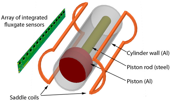
Figure 1.
The position sensor consists of an array of integrated fluxgate sensors and two excitation saddle coils. The sensor is attached onto the pneumatic cylinder wall and has no moving parts.

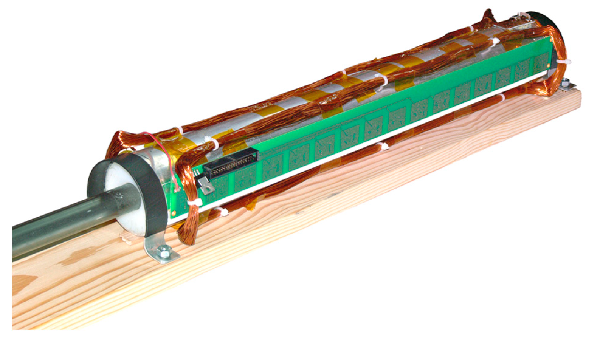
Figure 2.
The actual position sensor is made of 16 integrated fluxgate sensors and is attached to the pneumatic actuator model which is 50 cm long and 6 cm in diameter.
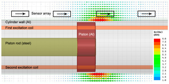
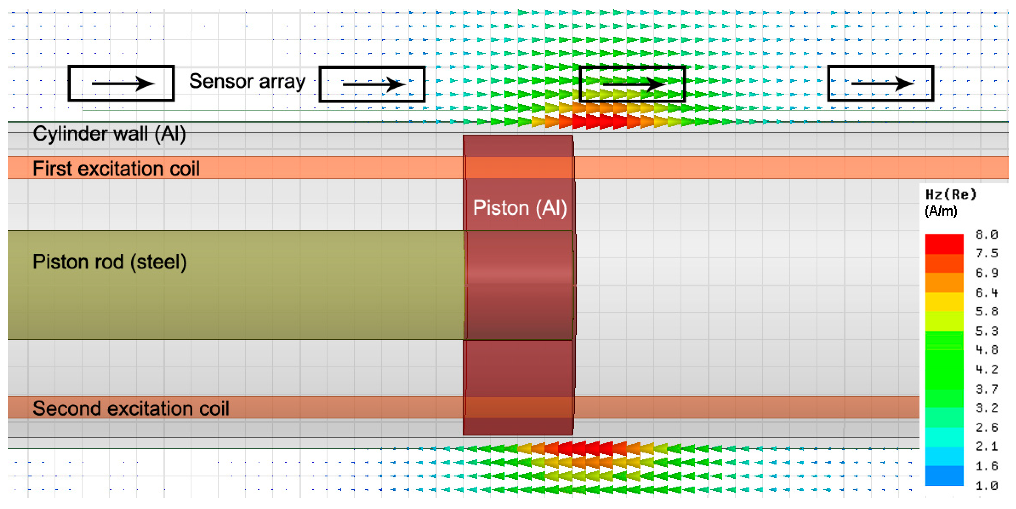
Figure 3.
Magnetic field component in axial direction outside the pneumatic cylinder simulated by FEM. Excitation field of 4 Hz in radial direction penetrates the aluminum wall and is substantially deformed near the end of the piston rod made of common magnetizable steel. Sensors are oriented in the axial direction and perpendicularly to the excitation field.
Each sensor output was evaluated by a synchronous demodulator implemented in software due to high number of channels (Figure 4). The measurement setup is suitable for assessment of sensor parameters, however for application e.g., in a feedback controlled system a real-time system is needed to eliminate a variable delay.
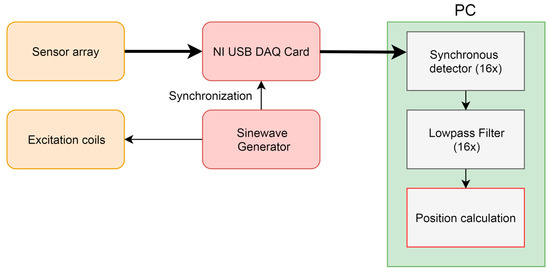
Figure 4.
Schematic diagram of signal processing.
3. Results
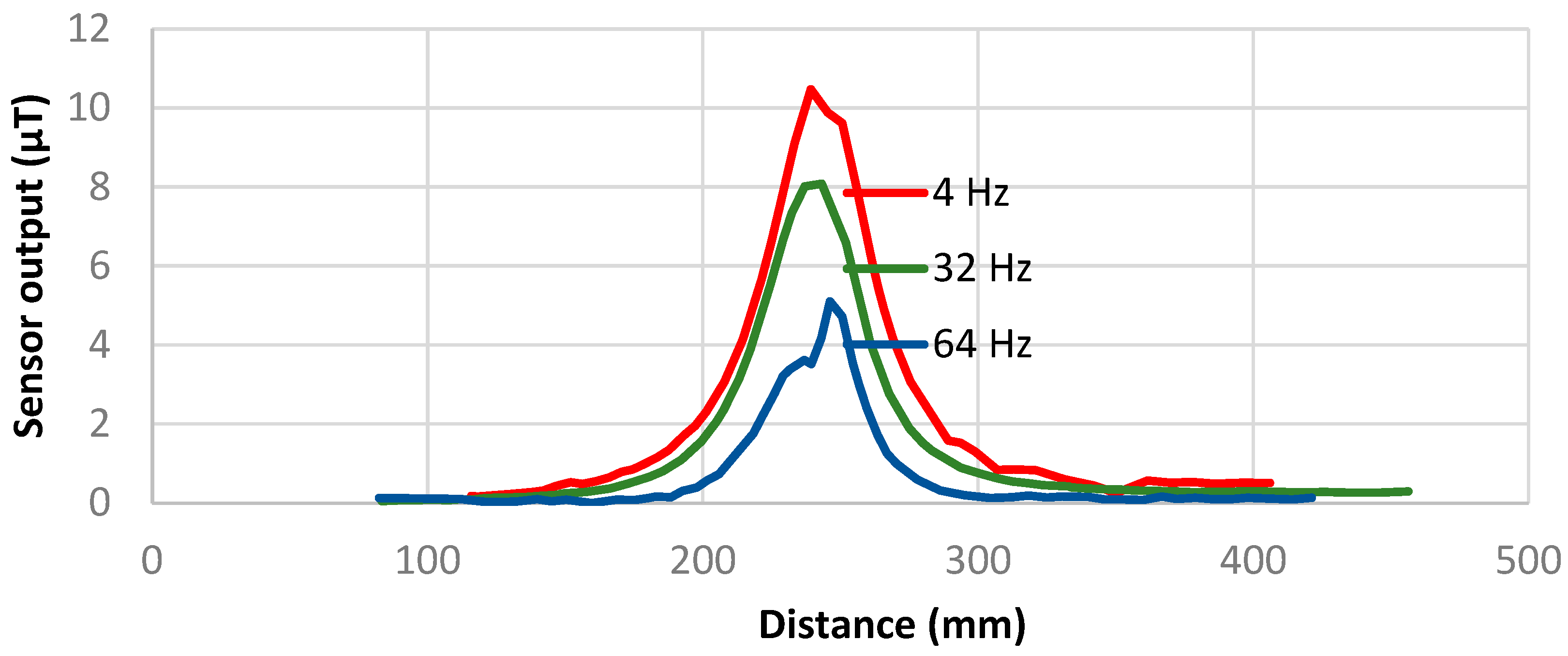
The response of the steel rod is frequency dependent. At very low frequencies only permeability effects contribute to the signal, at 64 Hz eddy current effects change noticeably the shape of characteristics (Figure 5). The selection of the used excitation frequency depends on the required dynamic properties of the designed sensor. We evaluated the error of position measurement with excitation frequency of 32 Hz and 16 sensors in the array with 3-cm spacing.
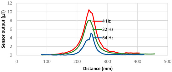
Figure 5.
Single sensor output vs. piston position for excitation frequency of 4 Hz, 32 Hz and 64 Hz.
To process the 16 output values of the sensor array the following methods were examined:
- The simplest approach is to find the maximum value and provide the position of the respective sensor. The position error is half of the spacing of sensors, in our case ±15 mm.
- Weighted average method ∑(outputi × distancei)/∑outputi reached an error of ±5 mm, see Figure 6. For noise reduction the weighted average is computed using only the three sensors with the maximum output. The error is three times better than the “maximum output” method with only moderate computing capacity requirements of a final microprocessor-based processing circuit.
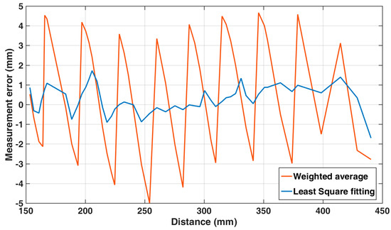 Figure 6. Positioning error throughout the central 300 mm stroke of the pneumatic actuator.
 - Least squares fitting method minimized the formula ∑(outputi – estimated_outputi)2, where the estimated output function is known by the single-sensor measurement in Figure 4. This output function is supposed to be the same for all 16 sensors. The only unknown coefficient of the model is the distance shift, so the computation time is reasonable. This method reached the position error better than ±2 mm (Figure 6). Disadvantage of this method is that the output function is likely to be different between distinct cylinder types and needs to be measured. Further improvement of accuracy would provide a lookup table method with a laborious calibration throughout the full range with a fine step.
4. Discussion
The sensor has no moving parts and is suitable e.g., for retrofit applications where magnet for position sensor is missing. The measuring principle needs a common magnetizable steel rod rather than stainless steel one which is however more expensive and less usual. Due to the low amplitude of the signal measured, which is about 1/1000 of the amplitude provided by a piston magnet, the position sensor is susceptible to the background magnetic noise. However if the noise is limited to a specified frequency, it can be avoided by shifting the excitation frequency.
Conflicts of Interest
The authors declare no conflict of interest.
References
- Ripka, P.; Vyhnanek, J.; Janosek, M.; Vcelak, J. AMR Proximity Sensor with Inherent Demodulation. IEEE Sens. J. 2014, 9, 3119–3123. [Google Scholar] [CrossRef]
- Reininger, T.; Welker, F.; Von Zeppelin, M. Sensors in position control applications for industrial automation. Sens. Actuators A Phys. 2006, 129, 270–274. [Google Scholar] [CrossRef]


Publisher’s Note: MDPI stays neutral with regard to jurisdictional claims in published maps and institutional affiliations. |
© 2017 by the authors. Licensee MDPI, Basel, Switzerland. This article is an open access article distributed under the terms and conditions of the Creative Commons Attribution (CC BY) license (https://creativecommons.org/licenses/by/4.0/).