1. Introduction
Capacitive MEMS microphones are widely adopted in many applications, such as smartphones, tablets and PCs. These microphones have excellent acoustic performances but dust or liquids of any kind can permanently damage them. On the other hand, piezoelectric microphones, based on direct piezoelectric effect, can be dust resistant and liquid resistant thanks to their structure. Therefore, they can be used not only in phones, but also in wearables and automotive applications. Moreover, they are suitable for all applications requiring zero power and wake-up under sound operation.
Aluminium nitride (AlN) is a piezoelectric material widely used in sensor applications because of its very low material losses, unlike other piezoelectric materials such as lead zirconate titanate (PZT) [
1]. Low loss is key in microphones because it is mandatory in order to get good SNR. Other positive features of AlN are negligible hysteresis, constant capacitance versus bias voltage and low dielectric constant (
εr ~ 10) allowing for fast transient behavior. AlN piezoelectric parameters can be further improved with scandium (Sc) doping [
2]. Thanks to all these advantages, AlN is a good choice for transducers fabrication, especially microphones.
In order to design innovative MEMS piezoelectric microphones, a flexible and reliable simulation platform (SP) is mandatory. FEM and lumped-element models for capacitive microphones [
3] and unimorph piezoelectric microphones [
4,
5] have already been presented. In this context, we developed a complete SP, fully integrating these two different modelling strategies. The environment we developed allows evaluating microphone SNR in a direct and robust way, suitable for single and multilayers piezoelectric stack, without any constraint on geometrical shape.
2. Simulation Platform
As shown in
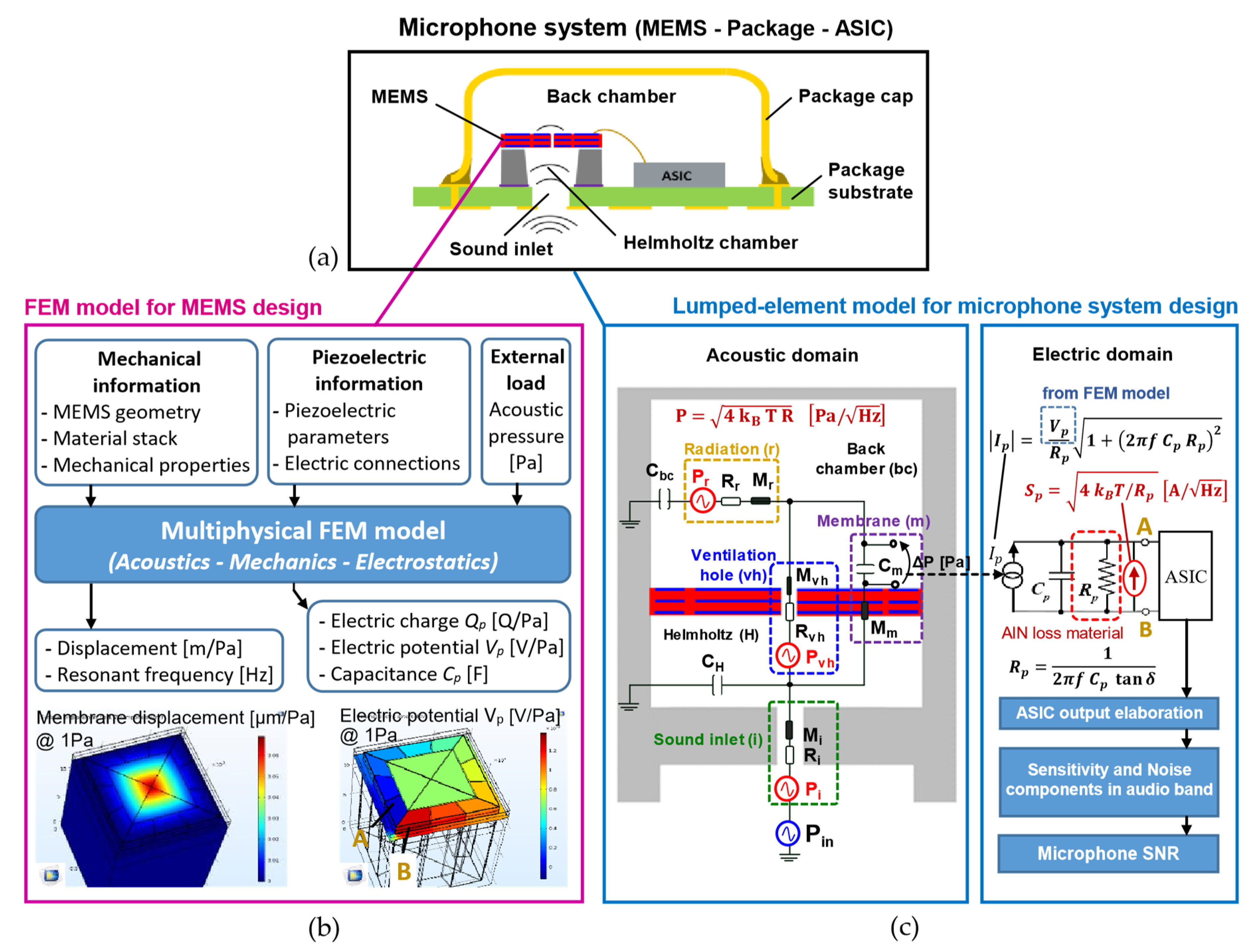
Figure 1a, a typical microphone system is made of three elements: a MEMS sensor that is the electro-mechanical part of the system, an ASIC for signal readout and conditioning and a package enclosing the two silicon elements. Microphones package is usually a cavity package made of a LGA substrate and a metallic or plastic cap.
First block of our SP is a multiphysical FEM model developed in COMSOL
® environment in order to study the acoustic mechanical interactions and the electrical behavior of the MEMS structure. As shown in the block scheme of
Figure 1b, FEM model inputs are any MEMS geometry, material stack and layer thicknesses, material mechanical properties and residual stresses, piezoelectric parameters and definition of electrode connections. Main aim of this model is unimorph (single layer) and bimorph (double layer) piezoelectric structures but it can be easily extended to multilayers. Multiple piezoelectric cells can be introduced and arbitrary connected with each other. According to acoustic pressure applied as a load and to boundary conditions defined, FEM calculates all the mechanical (deflection, resonance frequency) and electrical quantities (charge, potential and capacitance).
Second block of the SP allows studying MEMS-ASIC-package interplay by means of the equivalent electro-mechanical-acoustic lumped-element model developed and reported in
Figure 1c. The model includes all the main acoustic and electrical elements, in acoustic and electrical domains respectively, characterizing the piezoelectric MEMS microphone system. FEM results and analytical formulas define lumped parameter values. Lumped model is evaluated via Matlab
®-Simulink tool. External sound pressure is an equivalent acoustic source
Pin (in blue) as well as each noise source is an equivalent acoustic noise source
P (in red). When
Pin is active and noise sources
P are short-circuited, the model calculates sensitivity and frequency response of the microphone system in audio band (20 Hz–20 kHz).
When Pin is short-circuited and noise sources P are active, A-weighted microphone noise in audio band can be evaluated. SNR is defined as the ratio between sensitivity at 1 kHz and A-weighted noise in audio band.
3. Numerical and Experimental Results
The SP has been validated on the commercial piezoelectric microphone [
6] shown in
Figure 2a and used in this context as test vehicle. MEMS membrane presents four triangular cantilevers made of a bimorph of two AlN layers (in red) between three electrodes (in blue). Twelve piezoelectric cells, located in cantilever anchor area, are connected in a series-of-parallels configuration, in order to optimize total equivalent capacitance
Cp and total voltage
Vp between terminals A and B. Examples of FEM results, such as membrane displacement and electrostatic potential between terminals A and B, are shown in
Figure 1b.
Capacitance
Cp of the MEMS and resistance
Rp, related to AlN dielectric loss, have been evaluated with the experimental setup shown in
Figure 2b. Experimental
Cp (in blue) is almost constant in audio band. Measured
Cp value is in good agreement with FEM simulation. Measured
Rp values (in blue) have been fitted with theoretical model (in red) and material loss tan
δ has been estimated. We obtained tan
δ = 0.003, in agreement with literature [
1].
Figure 3a shows theoretical (in red) and experimental (in blue) sensitivity normalized with respect to 1 kHz. Roll-off point, defined as the frequency where normalized sensitivity is −3 dBr, is set by the air gap between the four cantilevers and controls MEMS low frequency response.
Figure 3b shows the contribution of each noise component to noise power spectral density (PSD) and their cumulated trend (MEMS), as calculated by the equivalent lumped-element model of
Figure 1c. Main noise contributor in audio band is AlN material loss (in red). This value can be adjusted by design with a proper
Cp choice (
Rp depends on
Cp and tan
δ), therefore the SP is key in order to find best noise trade-off.
Figure 3c summarizes simulation vs experimental results for sensitivity value at 1 kHz, A-weighted noise in audio band and SNR value.
4. Conclusions
A SP, which fully integrates FEM modelling for piezoelectric MEMS design and an equivalent electro-mechanical-acoustic lumped-element model for microphone system analysis, has been presented. The agreement between simulation and experimental results is excellent in terms of sensitivity, noise and SNR value. The proposed SP can be used as an effective tool for the development of new and innovative piezoelectric microphones and related SNR evaluation.
