Proceeding Paper

Co-Design and Control of a Magnetic Microactuator for Freely Moving Platforms †

1
Chair of Control Engineering, University of Augsburg, D-86159 Augsburg, Germany
2
Research Group for Modelling and Simulation of Mechatronic Systems, Jade University of Applied Sciences, D-26389 Wilhelmshaven, Germany
3
Department of Microsystems Engineering, University of Freiburg, D-79110 Freiburg im Breisgau, Germany
*
Author to whom correspondence should be addressed.
Presented at the First International Electronic Conference on Actuator Technology: Materials, Devices and Applications, 23–27 November 2020; Available online: https://iecat2020.sciforum.net/.
Proceedings 2020, 64(1), 23; https://doi.org/10.3390/IeCAT2020-08494
Published: 20 November 2020

Abstract

:
A current goal for microactuators is to extend their usually small working ranges, which typically result from mechanical connections and restoring forces imposed by cantilevers. In order to overcome this, we present a bistable levitation setup to realise free vertical motion of a magnetic proof mass. By superimposing permanent magnetic fields, we imprint two equilibrium positions, namely on the ground plate and levitating at a predefined height. Energy-efficient switching between both resting positions is achieved by the cooperation of a piezoelectric stack actuator, initially accelerating the proof mass, and subsequent electromagnetic control. A trade-off between robust equilibrium positions and energy-efficient transitions is found by simultaneously optimising the controller and design parameters in a co-design. A flatness-based controller is then proposed for tracking the obtained trajectories. Simulation results demonstrate the effectiveness of the combined optimisation.

1. Introduction

Microsystem technology has become an increasingly important research field over the past 40 years. Besides microelectronic circuits and miniaturised sensors, microactuators belong to an indispensable sub-branch with applications, e.g., in the automotive industry, medicine and energy harvesting fields. The versatile applicability originates from their ability to produce precise mechanical movements on a micrometer scale. However, the range of motion is in general limited by their design. In order to overcome this, various approaches have been proposed. Breguet et al. presented a piezoelectric stick and slip actuator that achieves accurate linear movements up to several centimetres [1]. In the study of Mita et al., an internally suspended mass was electrostatically driven, such that the actuator was moved by the impact between the mass and a stopper [2]. Since friction is a key element in such concepts, a modelling approach for stick and slip actuators was given by Edeler et al. [3]. Large working ranges can also be achieved by electromagnetic levitation. This principle is used for the design of a linear microactuator, in which a platform is levitated and able to move in the longitudinal direction [4,5]. The stability of levitation by inductive suspensions was proven by Poletkin et al. [6]. In general, the presented approaches suffer from various drawbacks, e.g., permanent energy consumption for creating any stable equilibrium position in case of electromagnetic levitation or the high dependence on friction. The latter corresponds to a loss of energy due to the undesirable conversion from kinetic energy into dissipated heat. Moreover, the performance heavily depends on the surface condition. In case of predefined resting positions and unidirectional motion, pseudo-levitation as in magnetic bearings [7] can be applied by using permanent magnetic fields.
Besides a suitable choice of the working principle, a controlled motion is essential for precision and effectiveness. For small displacements, a common choice is to linearise the system at an operating point to describe the local behaviour. In this case, linear control strategies can give satisfactory results [8]. For enlarged working ranges, however, nonlinearities can in general not be neglected. Advanced control methods such as flatness-based control [9,10] or backstepping [11] can be used to obtain precise motion. The overall efficiency of the controlled state trajectory, however, can strongly depend on the chosen actuator design. For an optimal outcome, both the design and controller should therefore be optimised simultaneously in a co-design, as shown in [12] for an electrostatically-driven actuator.
In this work, we introduce a cooperative, bistable microactuator setup, using both magnetic and piezoelectric actuation. The goal is to achieve stable equilibrium positions without the need for permanent energy input. The transition between the two imprinted resting positions is accomplished by an efficient control strategy that exploits the cooperation of the two single actuators, namely a piezoelectric stack actuator and an electromagnetic solenoid. To ensure an optimal trade-off between low energy consumption and the robustness of the resting positions, both the actuator design and controller are optimised simultaneously in a co-design.

2. Methods

We consider the cooperative microactuator system shown in Figure 1, where a magnetic proof mass within a glass tube can move between two equilibrium positions, namely resting on top of a piezoelectric stack actuator and levitating at a predefined upper position. This corresponds to the design presented by Schütz et al. [13], but with the extension of a second permanent magnet and the stack actuator. Starting at the lower equilibrium, the inverse piezoelectric effect is used to apply an impulse-like acceleration, i.e., a kick, to the proof mass. This is followed by a controlled electromagnetic catch at an upper equilibrium position, where the mass is stably suspended by the permanent magnetic field.
The objective is to achieve a robust, bistable characteristic without the need for a permanent energy input, as well as a fast and efficient transition between the resting positions. Therefore, a parameterised system model is derived and then optimised simultaneously with the controller in a co-design.

2.1. Modelling

The actuator consists of three coupled dynamical systems, namely a solenoid, a stack actuator and a movable mass. The current i ( t ) of the electromagnet is given as:
L d d t i ( t ) = u in ( t ) R i ( t ) ,
where R denotes the wire resistance, L the inductance and u in ( t ) the input voltage. For the piezoelectric actuator, a linear second order approximation is used [14]. Taking into account the effectively moved mass M of the piezo actuator, which is assumed to be a third of its overall mass, the deformation d ( t ) can be described by:
M d ¨ ( t ) = M g c A d ˙ ( t ) k A d ( t ) F c ( t ) + F u ( t ) ,
where g is the gravitational acceleration and c A the damping and k A the stiffness coefficients of the actuator, respectively. The forces F c ( t ) and F u ( t ) correspond to the contact force between the piezo actuator and the proof mass and the inverse piezoelectric effect by applying a voltage u A ( t ) . Similar to [15], we approximate the relation between the force and input voltage by a linear equation; hence:
F u ( t ) = F max U max u A ( t ) .
In (3), F max and U max are the maximum achievable force and its corresponding input voltage, respectively. Although the dynamics are nonlinear, we assume the model to be sufficiently representative for the short time of contact with the proof mass. Finally, the vertical motion z ( t ) of the proof mass is determined by the sum of forces:
m z ¨ = F pm ( z ) + F em ( z , i ) + F c ( z , z ˙ , d , d ˙ ) c f z ˙ | z ˙ | m g .
Note that the time dependencies are neglected for readability. The parameters c f and m denote the air friction coefficient and the mass of the proof mass. Moreover, the magnetic interaction is described by the permanent and electromagnetic forces F pm ( z ) , F em ( z , i ) , where the former corresponds to a superposition of the single forces F pm , j ( z ) , j = 1 , 2 . We assume fully magnetised, hard magnetic materials with remanence values B r , p , B r , pm , j for the proof mass and ring magnets. Thus, we can use the proportional relations ( B r , p B r , pm , j ) F pm , j ( z ) and ( B r , p i ) F em ( z , i ) [16,17]. Due to the linearity, we can now describe the magnetic forces by introducing z-dependent shape functions f pm , j ( z ) , f em ( z ) as:
F pm , j ( z ) = B r , p B r , pm , j f pm , j ( z ) ,
F em ( z , i ) = B r , p i f em ( z ) .
Instead of an analytical expression, these forces are computed numerically with ANSYS® Maxwell [18] for a grid of system states and parameters and are implemented as a spline-interpolated lookup table. It is noteworthy that we can inversely compute the shape functions from (5) and (), given the numerical simulation data of the forces with known remanence values and currents. In the case that the permanent and electromagnet centre points are given by z pm , j and z em , the force can easily be obtained by shifting the shape function.
For the computation of the contact force F c ( z , z ˙ , d , d ˙ ) between the piezoelectric actuator and the movable mass, a viscoelastic approximation adapted from the method of power-based restriction functions [19] is applied. Thus, by allowing a small overlap s ( t ) = z ( t ) d ( t ) between both objects, the counteracting force is proportional to an activation function R a ( s ) , which corresponds to a virtual, nonlinear spring. In contrast to the latter reference, we use the piecewise function:
R a ( s ) = 0 , if s 0 k s + τ k exp ( s τ ) 1 , otherwise .
For further details, the reader is referred to the corresponding work of Specker et al. [19].

2.2. Trajectory Planning and Control

The derived model is now used to find an efficient control strategy. We first consider both actuation principles separately and then give an outline of the overall approach.

2.2.1. Electromagnetic Actuation

Let us first highlight two relevant system properties of the electromagnetic actuation. On the one hand, the electromagnetic force is zero whenever the position of the proof mass coincides with the centre point of the solenoid; hence, F em ( z em , i ) = 0 , i R . On the other hand, the model is flat with respect to the output z ( t ) , allowing us to express the system states and input exactly by only the output and its derivatives [20]. Consider the assumption that z ( t ) z em , t .
We then predetermine a sufficiently differentiable output trajectory z ref ( t ) . By the definition of the flatness property, there exists a reversible state transformation between x = [ z , z ˙ , i ] and ξ = [ z , z ˙ , z ¨ ] . This can be used to inversely compute the reference input sequence:
u in , ref ( t ) = f 1 z ref , z ˙ ref , z ¨ ref , z ref ,
where f 1 ( · ) corresponds to the inverse relation between the output, its derivatives and the solenoid voltage after the state transformation, which can be found by reformulating (1), (4). That is, by feedforward application of u in , ref ( t ) and in the absence of disturbances, we achieve the desired reference motion z ref ( t ) without error, provided that the initial conditions are satisfied.
The reference input is now superimposed by an additional feedback controller for disturbance compensation. Here, we make use of the linearisability of the system via a feedback term [21]. By using the state transformation, we obtain the linear system:
ξ ˙ = 0 1 0 0 0 1 0 0 0 ξ + 0 0 1 ν ,
with a virtual input ν ( t ) . Since ν = z ( t ) , we can insert it into (8) and obtain an expression for u in ( t ) with dependence on ν ( t ) . Thus, the task is reduced to controlling the linear system. We propose a two-degree-of-freedom controller design, consisting of the feedforward term ν ref ( t ) = z ref ( t ) and a feedback control law ν ( t ) = K e ( t ) , resulting in ν ( t ) = ν ref ( t ) + ν ( t ) . Here, e ( t ) = ξ ref ( t ) ξ ( t ) is the state error, and the stabilising controller gain matrix K is found in terms of a linear quadratic regulator (LQR).
For the feedforward term, a suitable reference needs to be computed. The goal is to find a twice differentiable motion z ref ( t ) starting at initial state ξ 0 and terminating at ξ f after time T f . We achieve this by defining z ref ( t ) and subsequently integrating it. Here, we choose z ref ( t ) to be piecewise constant with n 3 equidistant time steps T, i.e.,
z ref ( t ) = u i , t [ T i , T ( i + 1 ) ] , i = 0 , , n 1 .
These trajectory parameters u i can be chosen arbitrarily. Only the last three parameters u n j , j = 1 , 2 , 3 have to be computed in a way that the three final state conditions are met.

2.2.2. Piezoelectric Actuation

So far, we have only focused on the electromagnetic actuation. Since there is a large distance between the lower equilibrium and the solenoid, initially accelerating the proof mass requires high electrical currents. A more suitable approach is to transfer the relevant force directly by a piezoelectric kick. Due to the short interaction time between the mass and the piezo actuator, we only use feedforward control in terms of a voltage spike. Here, the applied voltage:
u A ( t ) = u p 0.53 exp t τ 2 exp t τ 1
with τ 1 = 1 ms , τ 2 = 5 ms and the peak voltage u p U max is used as an approximation of the achievable voltage. In summary, the cooperative actuation starts with a kick, and the electromagnetically controlled catch is switched on after time T kick . The subsequently followed trajectory is precomputed such that it ends in the upper equilibrium position with zero velocity and acceleration. The permanent magnets then stably keep the proof mass in place. The reverse procedure is used for the direction toward the lower resting position. However, only the electromagnet can then be used.

2.3. Co-Design

For a fixed system, efficient trajectories can now be obtained by an optimisation over the trajectory parameters u i . However, the system design influences the overall optimality, which is indicated by the permanent magnetic force acting on the proof mass, as shown in Figure 2 for two different designs.
The equilibrium positions correspond to the intersection of the mirrored gravitational force F g with the magnetic and contact force characteristics. These are locally stable, if additionally, the force gradient is negative. Due to the counterforce of the stack actuator at the zero position, the stability criterion at this point is simplified, i.e., the point is stable if the magnetic force is lower than F g . This corresponds to the mass being pushed against the piezo actuator. For both setups shown in Figure 2, the resting positions are located at z = 0   mm and z = 2.5   mm , and their robustness depends on the force steepness around that point. A steep force is able to counteract small deviations, pushing the proof mass back into the resting position. In the case of the flat curve, the positive magnetic force compensates most of the gravitational force at the lower position. Thus, a small positive force disturbance is sufficient for the proof mass to inadvertently leave its equilibrium. Therefore, robust equilibria are preferred. However, the energy effort for the transition between these points increases with robustness, since larger counterforces have to be overcome. Thus, a trade-off has to be found. These and similar contradictory goals can be handled by simultaneously optimising the system and the controller in a co-design.
Consider the individual design and controller cost functions J d ( p d ) , J t ( p d ) , depending on the respective parameter vectors p d , p t , where the indices d and t denote the design and the trajectory. See Table 1 for an overview of the parameters. Since the controller costs are additionally influenced by the design parameters, minimising both cost functions individually can lead to suboptimal overall behaviour. Instead, we define a combined cost function J ( p ) with the extended parameter vector p = [ p d , p t ] and simultaneously optimise both the design and controller. With the respective weightings w d and w t , the optimisation can be mathematically expressed as:
min p w d J d ( p ) + w t J t ( p )
s . t . p P ,
where P denotes the constrained set of allowed parameters. The design costs evaluate stability and robustness, solely depending on the permanent magnetic field. Here, we penalise the deviation from reference forces F ref , low , F ref , up and the upper equilibrium gradient F ref , up , resulting in:
J d = w d , 1 F pm ( z eq , low ) F ref , low 2 + w d , 2 F pm ( z eq , up ) F g 2 + w d , 3 F pm ( z eq , up ) F ref , up 2 .
For given component dimensions, F pm depends on the remanence of both the proof mass and the magnetic rings, as well as the positions z pm , 1 , z pm , 2 . For the simplicity of the optimisation, we used a continuous set of remanence values, assuming that the final result can approximately be achieved by custom composite magnets of individual shape and dimension. The design can be then optimised over the parameters B r , j , z pm , j , j = 1 , 2 and B r , p . Concerning the trajectory efficiency, the quadratic cost function:
J t = k = 1 N w t , 1 ( z k z eq , k ) 2 + w t , 2 z ˙ k 2 + w t , 3 i k 2 + w t , 4 u in , k 2
is used, which penalises the deviation from the current reference equilibrium z eq { z eq , low , z eq , up } , high velocities, solenoid currents and the input effort at sampled time steps t = k T s with step width T s . The costs are directly influenced by the parameter vector p t , containing the values u i , the maximum transition time T f , the piezo voltage peak u p and the controller switch-on time T kick . Additionally, the efficiency indirectly depends on the design parameters of the magnetic field, as well as the solenoid centre position z em . The overall cost function can then be minimised by a suitable constrained optimisation algorithm.

3. Results

The co-design framework was implemented in MATLAB®, and the dynamics (1), (2), (4) were integrated numerically using the stiff ode23t solver. The optimisation problem is non-convex and partially discontinuous. The latter results from the piezoelectric kick and the stiffness of the contact model. Therefore, a genetic algorithm from the global optimisation toolbox [22] was used. See Table 2 for the fixed component and control parameters and Table 1 for an overview of the optimisation parameters and their linear bounds. The existence of both equilibrium positions is ensured by shifting the magnetic field to match the upper resting position and using a nonlinear constraint F pm ( 0 ) 0.5 F g for the lower position. For the following study, we used the weighting coefficients given in Table 3.
The trajectory to be optimised consists of a motion to the upper equilibrium z eq , up = 2.5  m m within T sim = 0.15 s and back to the lower position within the same time span. The actual transient time T f is divided into n = 9 equidistant intervals T, to which an individual, optimised motion parameter u i is assigned. The result is shown in Figure 3.
As can be seen in Figure 3a, fast trajectories in both the upwards and downwards direction are achieved with small overshoot and a transition time of T f = 97.1  m s . The optimised variables are given in Table 1. The bistability property is verified by both zero inputs at the equilibrium positions and magnetic field, which almost matches the reference points. In Figure 3a, the advantage of using the cooperation between the piezoelectric kick and the catch is clearly illustrated. Due to the kick, the proof mass is accelerated to a velocity of 0.1   m s −1, largely reducing the necessary voltage input. Without the piezoelectric input, the optimal trajectory requires an initial voltage of 38 V for achieving the same transient time. This is also reflected by the trajectory costs J t , which are 0.284 for the cooperative solution and 0.352 for the simulation without the kick.
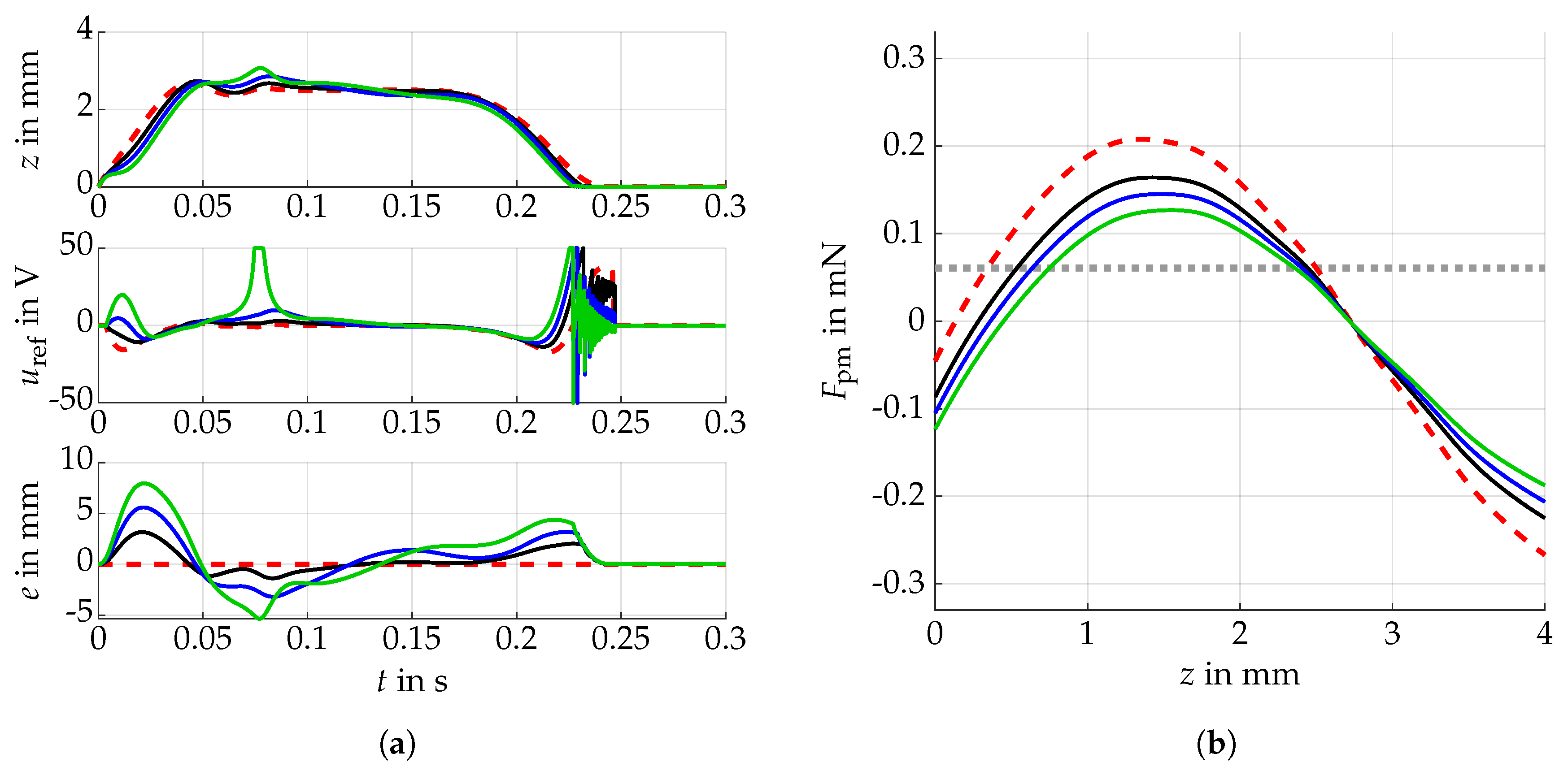
Given the optimised reference, we now study the trajectory following controller in the simulation. To achieve this, the reference is used as a lookup table for the feedforward term. In order to assess the disturbance compensation ability, model uncertainty is implemented, i.e., the magnetic field for the simulation is different than that used for computing the feedforward term. The reference magnetic field and its variations can be seen in Figure 4b, and the resulting controlled motion is visualised in Figure 4a.
The controller is still able to follow the reference trajectory, despite force deviations at a magnitude comparable to the gravitational force. The large motion deviation at the beginning is partly due to the fact that the kick has not been optimised for such forces pushing the movable mass against the piezo actuator. Thus, the significant increase in the solenoid voltage can be explained by the decreasing effect of the kick.

4. Discussion

The simulations illustrate the ability of the co-design algorithm to handle the contradictory goals effectively, as well as to find a suitable cooperation strategy. The initial kick greatly reduces the load on the solenoid. However, high inputs are still needed for the transition to the lower equilibrium. Decreasing the distance between the solenoid and the lower equilibrium can lead to stability issues, since the proof mass cannot be controlled near the solenoid centre. This could be solved by using an additional electromagnet. The implemented feedback control strategy shows good results in terms of compensating significant differences in the magnetic fields. It can be seen, however, that the proof mass cannot be guaranteed to remain below the solenoid centre for larger disturbances, resulting in undesired input voltage spikes, as seen in Figure 4a for the green line. Similar to the high voltages for the downwards motion, this can be avoided by using a second solenoid. In further studies, the number of stable equilibria will be increased together with the working range by additional electro- and permanent magnets. The simulative control approach currently assumes perfect state feedback. For the real system, however, a measurement system will be necessary. To this end, induction coils will be considered. Since only the velocity can be measured directly, an observer structure can reconstruct the needed signals. The first approaches will be implemented in simulation and combined with the controller. Moreover, the optimal placement of both actuation and sensing coils will be a non-trivial task. Therefore, an extension of the presented co-design framework can be considered.

5. Conclusions

In this paper, we present a novel, bistable microactuator design, which allows the fast and free motion of a magnetic proof mass in the vertical direction. For the transition between the equilibrium positions, a cooperative mechanism between a piezoelectric stack actuator and an electromagnetic solenoid is employed. We show that the achievable efficiency in terms of input effort depends on both the design and the controller. A co-design approach is therefore successfully applied to optimise the setup and trajectory at the same time, illustrating its usefulness for designing cooperative actuators. To follow a given reference trajectory, we design a flatness-based controller and show its effectiveness in terms of disturbance compensation in the simulation. The efficiency and travel range of the overall setup can even be increased by an additional solenoid, since this cancels the restriction to remain below the solenoid centre.

Author Contributions

Conceptualization, C.A., U.W., and T.B.; funding acquisition, C.A., U.W., and T.B.; methodology, M.O.; software, M.O.; investigation, M.O., A.S., and K.K.; writing, original draft preparation, M.O. and K.K.; visualization, M.O.; supervision, C.A., U.W., and T.B. All authors read and agreed to the published version of the manuscript.

Funding

This research was funded by the German Research Foundation (DFG) within the priority program SPP2206 “KOMMMA”, project “Kick and Catch—Cooperative Microactuators for Freely Moving Platforms”.

Conflicts of Interest

The authors declare no conflict of interest.

References

  1. Breguet, J.M.; Pérez, R.; Bergander, A.; Schmitt, C.; Clavel, R.; Bleuler, H. Piezoactuators for Motion Control from Centimeter to Nanometer. In Proceedings of the IEEE/RSJ International Conference on Intelligent Robots and Systems, Takamatsu, Japan, 31 October–5 November 2000; pp. 492–497. [Google Scholar]
  2. Mita, M.; Arai, M.; Tensaka, S.; Kobayashi, D. Fujita, H. A Micromachined Impact Microactuator Driven by Electrostatic Force. J. Microelectromech. Syst. 2003, 12, 37–41. [Google Scholar] [CrossRef]
  3. Edeler, C.; Meyer, I.; Fatikow, S. Modeling of stick-slip micro-drives. J. Micro-Nano Mechatron. 2011, 6, 65–87. [Google Scholar] [CrossRef]
  4. Ruffert, C.; Li, J.; Denkena, B.; Gatzen, H.H. Development and Evaluation of an Active Magnetic Guide for Microsystems With an Integrated Air Gap Measurement System. IEEE Trans. Magnet. 2007, 43, 2716–2718. [Google Scholar] [CrossRef]
  5. Ruffert, C.; Gehrking, R.; Ponick, B.; Gatzen, H.H. Magnetic Levitation Assisted Guide for a Linear Micro-Actuator. IEEE Trans. Magnet. 2006, 42, 3785–3787. [Google Scholar] [CrossRef]
  6. Poletkin, K.; Lu, Z.; Wallrabe, U.; Korvink, J.G.; Badilita, V. Stable dynamics of micro-machined inductive contactless suspensions. Int. J. Mech. Sci. 2017, 131, 753–766. [Google Scholar] [CrossRef]
  7. Safaeian, R.; Heydari, H. Optimal design of passive permanent magnet bearings. In Proceedings of the 27th Iranian Conference on Electrical Engineering, Yazd, Iran, 30 April–2 May 2019; pp. 458–463. [Google Scholar]
  8. Tzes, A.; Nikolakopoulos, G.; Dritsas, L.; Koveos, Y. Multi-Parametric Hinf Control of a Micro-actuator. In Proceedings of the 16th Triennial World Congress, Prague, Czech Republic, 4–8 July 2005; pp. 964–969. [Google Scholar]
  9. Zhu, G.; Lévine, J.; Praly, L.; Peter, Y. Flatness-Based Control of Electrostatically Actuated MEMS With Application to Adaptive Optics: A Simulation Study. J. Microelectromech. Syst. 2006, 15, 1165–1174. [Google Scholar] [CrossRef]
  10. Owusu, K.O.; Lewis, F.L. Solving the “Pull-in” Instability Problem of Electrostatic Microactuators using Nonlinear Control Techniques. In Proceedings of the 2nd IEEE International Conference on Nano/Micro Engineered and Molecular Systems, Bangkok, Thailand, 16–19 January 2007; pp. 1190–1195. [Google Scholar]
  11. Zhu, G.; Saydy, L. Robust Output Feedback Control of an Electrostatic Micro-Actuator. In Proceedings of the American Control Conference, New York, NY, USA, 9–13 July 2007; pp. 3192–3197. [Google Scholar]
  12. Peters, D.L.; Kurabayashi, K.; Papalambros, P.Y.; Ulsoy, A.G. Co-Design of a MEMS Actuator and Its Controller Using Frequency Constraints. In Proceedings of the ASME Dynamic Systems and Control Conference, Ann Arbor, MI, USA, 20–22 October 2008; pp. 801–807. [Google Scholar]
  13. Schütz, A.; Hu, S.; Rudnyi, E.B.; Bechtold, T. Electromagnetic System-Level Model of Novel Free Flight Microactuator. In Proceedings of the 21st International Conference on Thermal, Mechanical and Multi-Physics Simulation and Experiments in Microelectronics and Microsystems, Cracow, Poland, 6–27 July 2020; pp. 1–6. [Google Scholar]
  14. Goldfarb, M.; Celanovic, N. A lumped parameter electromechanical model for describing the nonlinear behavior of piezoelectric actuators. J. Dyn. Syst. Meas. Control 1997, 119, 478–485. [Google Scholar] [CrossRef]
  15. Main, J.A.; Garcia, E. Piezoelectric Stack Actuators and Control System Design: Strategies and Pitfalls. J. Guid. Control Dyn. 1997, 20, 478–485. [Google Scholar] [CrossRef]
  16. Agashe, J.S.; Arnold, D.P. A study of scaling and geometry effects on the forces between cuboidal and cylindrical magnets using analytical force solutions. J. Phys. D Appl. Phys. 2008, 41, 1–9. [Google Scholar] [CrossRef]
  17. Ravaud, R.; Lemarquand, G.; Babic, S.; Lemarquand, V.; Akyel, C. Cylindrical Magnets and Coils: Fields, Forces, and Inductances. IEEE Trans. Magnet. 2010, 46, 3585–3590. [Google Scholar] [CrossRef]
  18. Ansys Inc. ANSYS Electronics Desktop, Release 2020 R1; Ansys Inc.: Canonsburg, PA, USA, 2020. [Google Scholar]
  19. Specker, T.; Buchholz, M.; Dietmayer, K. Dynamical Modeling of Constraints with Friction in Mechanical Systems. In Proceedings of the 8th Vienna International Conference on Mathematical Modelling, Vienna, Austria, 18–20 February 2015; pp. 514–519. [Google Scholar]
  20. Fliess, M.; Lévine, J.; Martin, P.; Rouchon, P. Flatness and defect of non-linear systems: Introductory theory and examples. Int. J. Control 1995, 61, 1327–1361. [Google Scholar] [CrossRef]
  21. Charlet, B.; Lévine, J. On dynamic feedback linearization. Syst. Control Lett. 1989, 13, 143–151. [Google Scholar] [CrossRef]
  22. The MathWorks Inc. MATLAB and Global Optimization Toolbox (R2019a); The MathWorks Inc.: Natick, MA, USA, 2019. [Google Scholar]
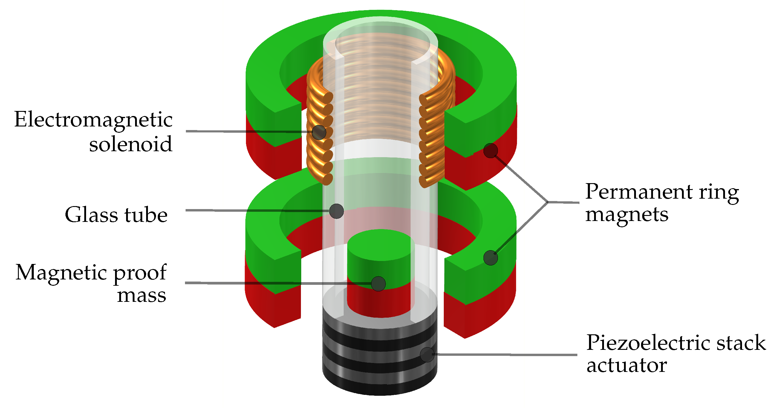
Figure 1. The schematic of the magnetic microactuator is shown. It consists of a movable proof mass within a guiding glass tube, a piezoelectric stack actuator (kick actuator), permanent magnets and an electromagnet (catch actuator).
Proceedings 64 00023 g001
Figure 2. Stationary magnetic force characteristics depending on the proof mass position for two different magnet setups. Both the strong magnetic field (solid, black) and the weak field (dashed, red) have stable equilibrium positions at z = 0 and z = 2.5 mm . The dotted, grey line corresponds to the magnitude of the gravitational force.
Proceedings 64 00023 g002
Figure 3. Optimised result: (a) The proof mass motion z ref ( t ) with corresponding input u ref ( t ) , accelerated by a kick (solid, black), and an optimised trajectory without kick (dashed, red). The dotted, grey line shows the reference equilibrium over time. (b) The magnetic field (solid, black), resulting from the superposition of the two single magnetic fields (dashed, red and dashed-dotted, blue), nearly fulfils the target specifications (dashed and crosses, grey). The gravitational force is illustrated by the grey, dotted line.
Proceedings 64 00023 g003
Figure 4. Flatness-based following control with model uncertainty is implemented. (a) The feedback controller is mostly able to compensate the model differences, but for the largest magnetic field deviation (solid, green), the position of the proof mass briefly coincides with the solenoid centre. The dashed, red line corresponds to the reference. (b) In each simulation, the magnetic force deviates more from the reference (dashed, red).
Proceedings 64 00023 g004
Table 1. Optimisation variables p d and p t with corresponding linear bounds used in the co-design.
VariableDescriptionLower BoundUpper BoundOptimised Value
B r , pm , 1 Ring magnet remanence 0.1  T 1 T 0.2433  T
B r , pm , 2 Ring magnet remanence 1  T 1 T 0.1425  T
B r , p Proof mass remanence 0.01  T 1 T 0.9977  T
z pm , 1 Position of ring magnet 11 m m 10 m m 2.773  m m
z pm , 2 Position of ring magnet 2 7.5  m m 1 m m 5.329  m m
z em Position of solenoid 2.8  m m 3.087  m m
u p Piezo actuator voltage peak0 V U max 65.78  V
u i Third motion derivative
T kick Controller switch on time0 s 0.02  s 3.71  m s
T f Maximum transient time 1.1  T kick T sim 97.12  m s
Table 2. Fixed design and control parameters that are used in the simulation. LQR, linear quadratic regulator.
DescriptionValueDescriptionValue
Inner radius (ring magnets) 4.5  m m U max (piezo) 100  V
Outer radius (ring magnets) 5.0  m m Stiffness (piezo) 1.0909  k N m m −1
Height (ring magnets) 1.5  m m Surface (piezo)9 m m 2
Inner radius (solenoid) 0.8  m m Height (piezo)21 m m
Outer radius (solenoid) 2.5  m m Mass (piezo) 1.8  g
Height (solenoid) 1.5  m m Diameter (proof mass) 1.0  m m
Wire diameter (solenoid) 25   μ m Height (proof mass) 1.0  m m
Specific resistance (solenoid) 18   n Ω m Density (proof mass)7874 k g m −3
Number of coils (solenoid)4000State penalty Q (LQR) diag ( [ 5 × 10 12 , 2 × 10 9 , 2 × 10 3 ] )
F max (piezo)360 N Input penalty R (LQR)1
Table 3. Weighting coefficients of the cost functions.
ParameterValueParameterValue
w d 8 w t , 1 2.22× 10 4
w d , 1 28 w t , 2 0
w d , 2 55 × 10 6 w t , 3 0.25
w d , 3 70 × 10 7 w t , 4 2.22× 10 7
w t 1
Publisher’s Note: MDPI stays neutral with regard to jurisdictional claims in published maps and institutional affiliations.