Abstract

Reliable Damping Simulation of Highly Perforated Micro-Electro-Mechanical Systems through Physical Compact Modeling †

Chair of Physics of Electrotechnology, TU Munich, 80333 Munich, Germany
*
Author to whom correspondence should be addressed.
Presented at the XXXV EUROSENSORS Conference, Lecce, Italy, 10–13 September 2023.
Proceedings 2024, 97(1), 176; https://doi.org/10.3390/proceedings2024097176
Published: 11 April 2024

Abstract

:
We present an approach to estimate damping in highly and irregularly perforated microplates over a wide range of pressures applying physics-based compact models implemented in a flux-conserving finite network. The models are coded in Verilog A, which allows for simulation using a standard circuit simulator. This provides an efficient and customizable way to determine damping beyond the state of the art, and thus, to tailor and design the dynamic operation of MEMS in a predictive manner.

1. Introduction

Most micromechanical structures are highly perforated because of fabrication processes but also to adjust damping and their dynamic behavior. Therefore, it is necessary to find a reliable way to model damping in MEMS, which depends decisively on the shape, number and distribution of perforations. Most modeling approaches assume uniformly perforated plates [1,2], which is often not applicable, especially in elaborated “real-world” MEMS devices. In the following, we introduce an approach that allows us to determine pressure-dependent damping in arbitrarily perforated structures. The simulation results are compared to measurements of test structures designed in a typical MEMS fabrication process.

2. Modeling Approach and Simulation Concept

Due to the complex geometry of MEMS devices and the involved fluid–mechanical interaction, calculation of damping on a continuous-field level is, in general, not possible. The method of choice is therefore to apply physics-based compact models, which scale appropriately with the geometry and environmental parameters. To this end, we apply a distributed finite network modeling the flow underneath the non-perforated parts of the plate combined with compact models accounting for the pressures drops due to the outflow at the perforations and the edges, respectively [3]. The flow underneath the plate is described by the Reynolds equation. An equivalent circuit comprising a fluidic resistor, capacitor and source models the laminar flow, compression of fluid and flow generated by the varying gap height, respectively. Outflow at the edges and through square-shaped perforations is modeled by Poiseuille flow-like models. To account for the transition region between the gap underneath the plate and the perforations, we use a model similar to the boundary model in [3], and for the flow out of the perforations into the ambient environment, we introduce an orifice model. To take high Knudsen numbers into account, we use the correction factors described in [4].
All compact models are coded in Verilog A. The model generation from a meshed geometry (e.g., by FEM) is automated by a MATLAB code, which sorts the features of the structure into respective categories, i.e., part of the boundary, a hole or the solid body, and connects the respective models to form a flux-conserving finite network of the entire structure, which can be implemented in a standard circuit simulator. A variety of dedicated, custom-made test structures are designed and characterized using a Laser Doppler Vibrometer (LDV) to validate the simulation approach.

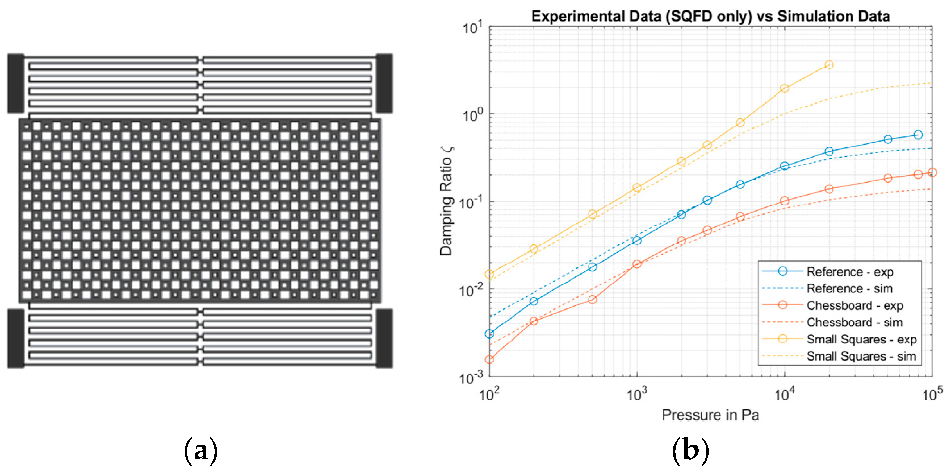
3. Simulation Results of Exemplary Test Structures and Comparison to Measurements

Figure 1a depicts a test structure with two differently sized perforations arranged in a checkered manner (“chessboard”, CB). It is suspended by four folded springs, which ensure out-of-plane motion of the plate. Two additional, uniformly perforated test structures with small holes (same size as small perforations of the CB, “Small Squares”) and perforations with dimensions lying between the large and small holes of the CB (“Reference”), respectively, were investigated. The simulated damping ratios are depicted in Figure 1b (dashed lines). They reveal a reasonable pressure dependence, and the difference in damping between the three test structures complies with the physical expectations.
The measured data obtained by the pressure-dependent LDV are compared to the simulated data and show an impressive overall match regarding the slope as well as the general course of the curve. Especially in the pressure range between 200 Pa and 10 kPa, there is only a small offset between the two data sets. This is potentially due to uncertainties in the compact models of the holes. Although the model scales with perforation geometries, it might over/underestimate the damping for smaller/larger holes, respectively. Figure 1b also shows that damping is underestimated at ambient pressures above 10 kPa, which is the so-called transition region between continuum regime and molecular flow regime in the case of the considered device geometries. Further investigations (e.g., by FEM simulations) are needed in order to improve the models in this respect. However, the results prove the predictive power of the presented approach and its potential for the design of large-scale, complex devices with multiple and varying perforation patterns.

Author Contributions

Conceptualization, F.M., B.L. and G.S.; methodology, F.M.; validation, F.M. and B.L.; investigation, F.M.; data curation, F.M.; writing—original draft preparation, F.M.; writing—review and editing, G.S. and F.M.; visualization, F.M. and B.L.; supervision, G.S.; project administration, G.S. All authors have read and agreed to the published version of the manuscript.

Funding

This research received no external funding.

Institutional Review Board Statement

Not applicable.

Informed Consent Statement

Not applicable.

Data Availability Statement

No new data were created.

Acknowledgments

We thank Robert Bosch GmbH, Reutlingen (namely Monika Koster), for providing the test structures.

Conflicts of Interest

The authors declare no conflict of interest.

References

  1. Bao, M.; Yang, H.; Sun, Y.; Wang, Y. Squeeze-film air damping of thick hole-plate. Sens. Actuators A Phys. 2003, 108, 212–217. [Google Scholar] [CrossRef]
  2. Veijola, T.; Raback, P. Methods for Solving Gas Damping Problems in Perforated Microstructures Using a 2D Finite-Element Solver. Sensors 2007, 7, 1069–1090. [Google Scholar] [CrossRef]
  3. Niessner, M.; Schrag, G. Mixed-Level Approach for the Modeling of Distributed Effects in Microsystems. In System-Level Modeling of MEMS; John Wiley & Sons, Ltd.: Hoboken, NJ, USA, 2013; pp. 163–189. [Google Scholar]
  4. Sattler, R. Physikalisch Basierte Mixed-Level Modellierung von Gedämpften Elektromechanischen Mikrosystemen. Ph.D. Thesis, Technische Universität München, Munich, Germany, 2007. [Google Scholar]
  5. Sumali, H. Squeeze-film damping in the free molecular regime: Model validation and measurement on a MEMS. J. Micromech. Microeng. 2007, 17, 2231–2240. [Google Scholar] [CrossRef]
Figure 1. (a) Top view of the “chessboard” test structure. (b) Pressure-dependent damping ratio due to SQFD: comparison of simulation results with experimentally extracted data of three different test structures. Non-viscous damping (e.g., structural damping) is subtracted from the measurement as in [5].
Proceedings 97 00176 g001
Disclaimer/Publisher’s Note: The statements, opinions and data contained in all publications are solely those of the individual author(s) and contributor(s) and not of MDPI and/or the editor(s). MDPI and/or the editor(s) disclaim responsibility for any injury to people or property resulting from any ideas, methods, instructions or products referred to in the content.

