Abstract
Employing a tri-electrode electrostatic actuator revealed a significant improvement in reducing the controlling voltage. However, the primary electrode fixed voltage can be a few times higher than the conventional topology. In this work, materials with relative permittivity of εr = 4.2, 6.2 and 10 were explored as the spacing material to reduce the primary voltage, and the results are compared with using air. Simulations showed that the controlling voltage can be reduced more than two times (at εr = 4.2) compared to the conventional topology while the primary electrode voltage required is lower than for air spacing and not more than two times larger than the conventional.
1. Introduction
The pull-in effect has always been one of the main design challenges of MEMS electrostatic actuators. In the conventional parallel plate topology, the actuator’s travel range is limited to one-third of the gap spacing between the MEMS moving electrode and the stationary electrodes (D1). The primary solution to the issue is to increase the gap spacing, which results in a higher required controlling voltage. There have been various approaches to reducing the controlling voltage besides increasing the range of motion [1]. Tri-electrode topology is another solution for reducing the controlling voltage, having two stationary controlling voltages. Figure 1 shows the conventional actuator configuration vs. the proposed tri-electrode topology. The tri-electrode consists of one perforated intermediate electrode with VI varying voltage and a solid electrode with fixed VP voltage. Simulation studies alongside experimental studies were carried out to show the performance of the actuator [2]. It was also shown that using a thicker gap-spacing material (εr > 1) between the stationary electrodes (compared to filling with air/vacuum, εr = 1) helps to simplify the fabrication while preserving the higher actuator’s performance compared to the conventional topology. In this work, the impact of using different materials on the actuator’s performance is investigated.
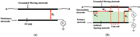
Figure 1.
(a) Conventional parallel plate electrostatic actuator topology with VC varying controlling voltage and (b) tri-electrode electrostatic actuator topology with fixed VP and varying VI controlling voltage.
2. Methods and Studies
Restoring spring force method and the FEM method were employed to extract the displacement vs. controlling voltage (VI) response curves [3]. Each response curve is characterized by the snap-down voltage (VS for conventional) and the displacement range (DS for conventional) before snap-down. The figure of merit (FOM) is defined as the actuator displacement per controlling unit voltage (VC or VI). The tri-electrode simulations are normalized to the conventional topology’s characteristics (DS = 1/3 D1 and FOMS = DS/VS) to represent the improvements. The tri-electrode topology was studied in three modes of unipolar (FOMu), bipolar (FOMb) and maximum displacement. Materials with relative permittivity of εr = 1, 4.2, 6.2 and 10 were explored as the spacing material between the stationary electrodes. The simulations were repeated for two different intermediate electrode gap spacings (WS = 3WE and 18WE) illustrated in Figure 2, and the results are summarized in Table 1.
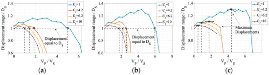
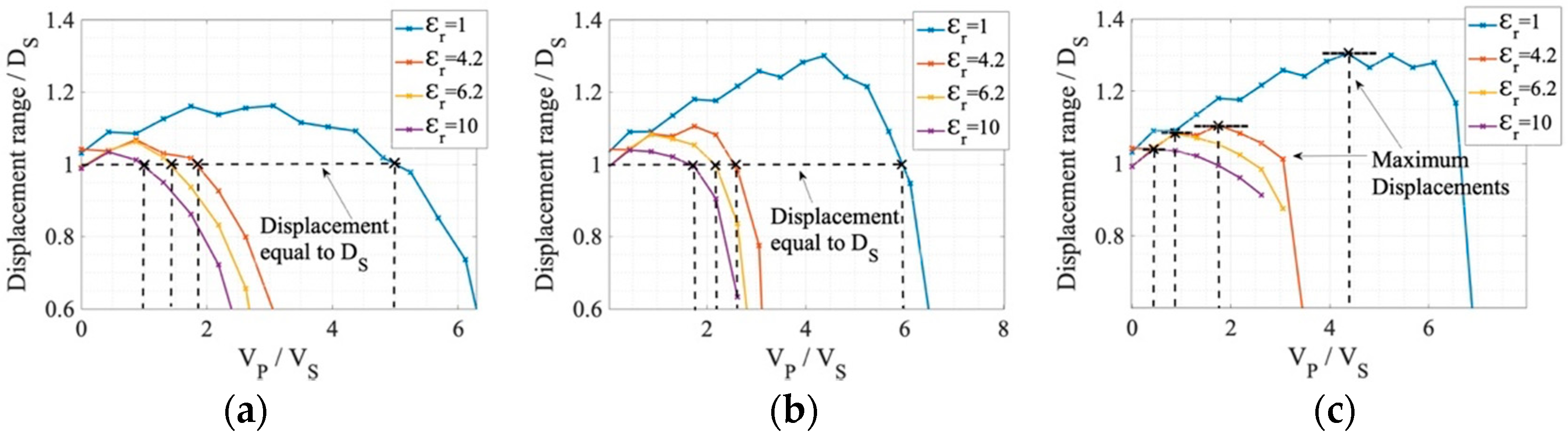
Figure 2.
Displacement vs. VP for (a) unipolar, (b) bipolar and (c) max displacement at D2 = 1.67D1 and WS = 3WE.

Table 1.
FOM (unipolar and bipolar) and maximum displacement for WS = 3WE and 18WE for εr = 1, 4.2, 6.2 and 10.
3. Discussion and Conclusions
Simulations show that the higher the permittivity of the solid material, the smaller VP at which the DS displacement occurs. However, the maximum displacement possible before snap-down and FOM (unipolar and bipolar) are higher at a smaller εr. In all cases, the larger gap spacing (WS = 18WE) provides greater maximum displacement possible before snap-down, but a lower FOM. Comparing the cases of air (εr = 1) and εr = 4.2, and for the gap spacing WS = 3WE, we see that for bipolar operation, the controlling voltage is reduced by more than two times (2.12 FOMS), needing a primary electrode voltage VP = 2.5VS, while the case of air requires a higher primary voltage for FOM improvement.
Author Contributions
Conceptualization, M.A. and C.S.; methodology, M.A. and C.S.; investigation, M.A., C.S. and B.P.; writing-original draft, M.A.; writing-review and editing, C.S. and B.P.; software, M.A.; validation, M.A.; visualization, M.A.; formal analysis, M.A. and C.S.; supervision, C.S.; project administration, C.S.; funding acquisition, C.S. and B.P.; resources, B.P. All authors have read and agreed to the published version of the manuscript.
Funding
This research was funded by the HTSN program at the National Research Council Canada.
Institutional Review Board Statement
Not applicable.
Informed Consent Statement
Not applicable.
Data Availability Statement
Data sharing does not apply to this article as no new data were analyzed or created.
Conflicts of Interest
The authors declare no conflicts of interest.
References
- Zhang, W.M.; Yan, H.; Peng, Z.K.; Meng, G. Electrostatic pull-in instability in MEMS/NEMS. Sens. Actuator A Phys. 2014, 214, 187–218. [Google Scholar] [CrossRef]
- Allameh, M.; Park, B.; Shafai, C. Experimental analysis of a low controlling voltage tri-electrode MEMS electrostatic actuator for array applications. J. Micromech. Microeng. 2023, 33, 035008. [Google Scholar] [CrossRef]
- Allameh, M.; Park, B.; Shafai, C. Enhanced travel range bipolar trielectrode electrostatic actuator using extended background electrode. In Proceedings of the MOEMS and Miniaturized Systems XXI, San Francisco, CA, USA, 22 January—28 February 2022; p. 120130. [Google Scholar]

Disclaimer/Publisher’s Note: The statements, opinions and data contained in all publications are solely those of the individual author(s) and contributor(s) and not of MDPI and/or the editor(s). MDPI and/or the editor(s) disclaim responsibility for any injury to people or property resulting from any ideas, methods, instructions or products referred to in the content. |
© 2024 by the authors. Licensee MDPI, Basel, Switzerland. This article is an open access article distributed under the terms and conditions of the Creative Commons Attribution (CC BY) license (https://creativecommons.org/licenses/by/4.0/).