Article

Three-Dimensional Trajectory and Resource Allocation Optimization in Multi-Unmanned Aerial Vehicle Multicast System: A Multi-Agent Reinforcement Learning Method

1
The Key Laboratory of Universal Wireless Communication, Ministry of Education, Beijing University of Posts and Telecommunications, Beijing 100876, China
2
Shenzhen Institute, Beijing University of Posts and Telecommunications, Shenzhen 518055, China
*
Author to whom correspondence should be addressed.
Drones 2023, 7(10), 641; https://doi.org/10.3390/drones7100641
Submission received: 30 August 2023 / Revised: 28 September 2023 / Accepted: 18 October 2023 / Published: 19 October 2023
(This article belongs to the Special Issue Resilient Networking and Task Allocation for Drone Swarms)

Abstract

:
Unmanned aerial vehicles (UAVs) are able to act as movable aerial base stations to enhance wireless coverage for edge users with poor ground communication quality. However, in urban environments, the link between UAVs and ground users can be blocked by obstacles, especially when complicated terrestrial infrastructures increase the probability of non-line-of-sight (NLoS) links. In this paper, in order to improve the average throughput, we propose a multi-UAV multicast system, where a multi-agent reinforcement learning method is utilized to help UAVs determine the optimal altitude and trajectory. Intelligent reflective surfaces (IRSs) are also employed to reflect signals to solve the blocking problem. Furthermore, since the UAV’s onboard power is limited, this paper aims to minimize the UAVs’ energy consumption and maximize the transmission rate for edge users by jointly optimizing the UAVs’ 3D trajectory and transmit power. Firstly, we deduce the channel capacity of ground users in different multicast groups. Subsequently, the K-medoids algorithm is utilized for the multicast grouping problem of edge users based on transmission rate requirements. Then, we employ the Multi-Agent Deep Deterministic Policy Gradient (MADDPG) algorithm to learn an optimal solution and eliminate the non-stationarity of multi-agent training. Finally, the simulation results show that the proposed system can increase the average throughput by 14 % approximately compared to the non-grouping system, and the MADDPG algorithm can achieve a 20 % improvement in reducing the energy consumption of UAVs compared to traditional deep reinforcement learning (DRL) methods.

1. Introduction

Recently, unmanned aerial vehicles (UAVs) have attracted much attention due to their flexible position adjustment capability, which enhances the probability of line-of-sight (LoS) communication links to ground users (GUs). In wireless communication systems, UAVs can provide storage and computational resources to alleviate the communication pressure of the whole network. UAVs can be used as relays between GUs and ground base stations (GBSs) in a store-carry-forward manner. They can also serve as aerial base stations to improve the coverage of GBSs. Additionally, overloaded GBSs can offload the traffic to UAVs. Therefore, UAVs are widely employed in scenarios such as disaster management, traffic monitoring, and emergency rescue, assuming the roles of data coverage, data collection, and information transmission.
In this paper, UAVs are considered to act as aerial base stations. When utilized as an aerial mobile base station to serve GUs, UAVs possess the following advantages [1]:
  • On-demand deployment: While conventional terrestrial base stations are fixed and immovable, UAVs are able to be deployed more flexibly and on-demand in accordance with GUs’ locations.
  • Better communication quality: Instead of more obstacle blocking between GBSs and GUs, the air-to-ground link is dominated more by the LoS link.
  • Mobility over time: UAVs have the capacity to move over time, adjusting their positions to satisfy the demands of GUs and enhance communication performance.
Meanwhile, the research about using UAVs as aerial base stations has encountered challenges, as follows:
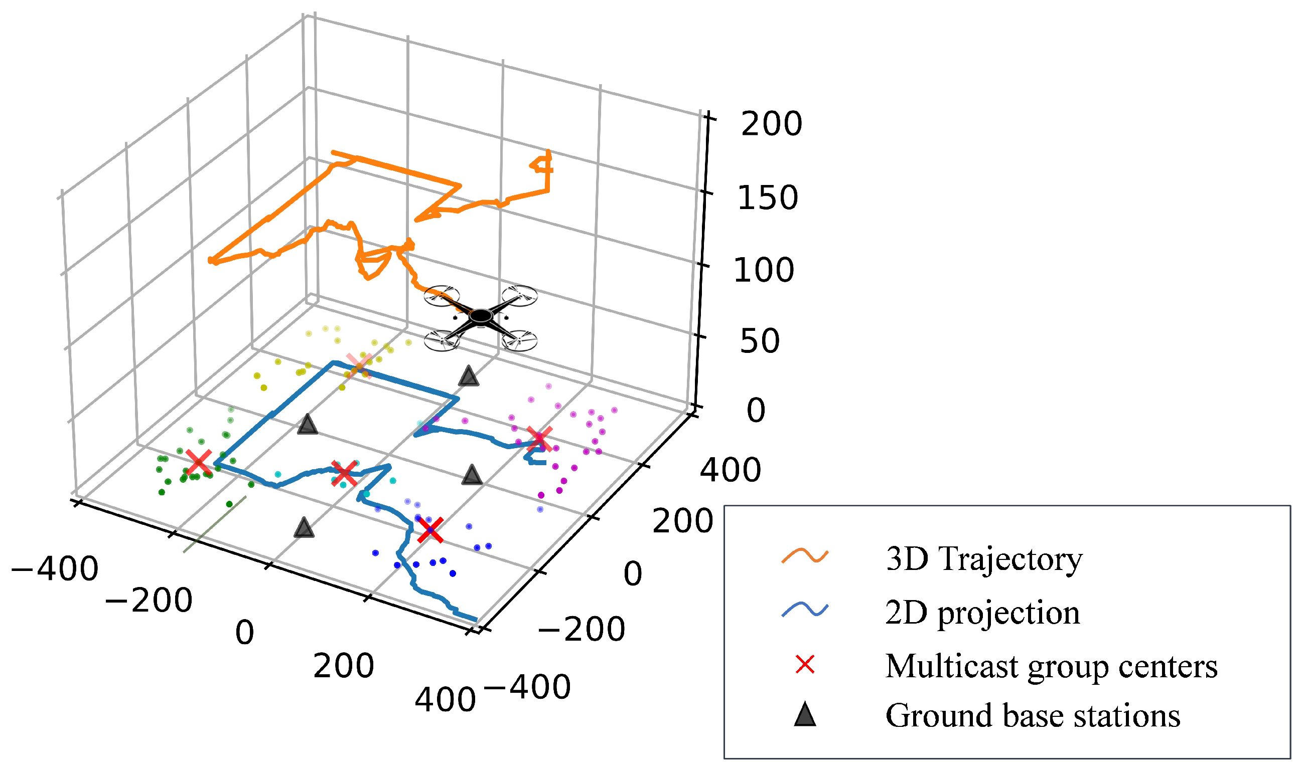
  • Trajectory design complexity: Since UAVs can move in multiple dimensions and need to be positioned to meet the needs of GUs; optimal deployment and trajectory design strategies need to be addressed.
  • Energy limitation: How to optimize the performance with the restricted energy needs to be taken into account because UAVs consume energy both during their flight and communication.
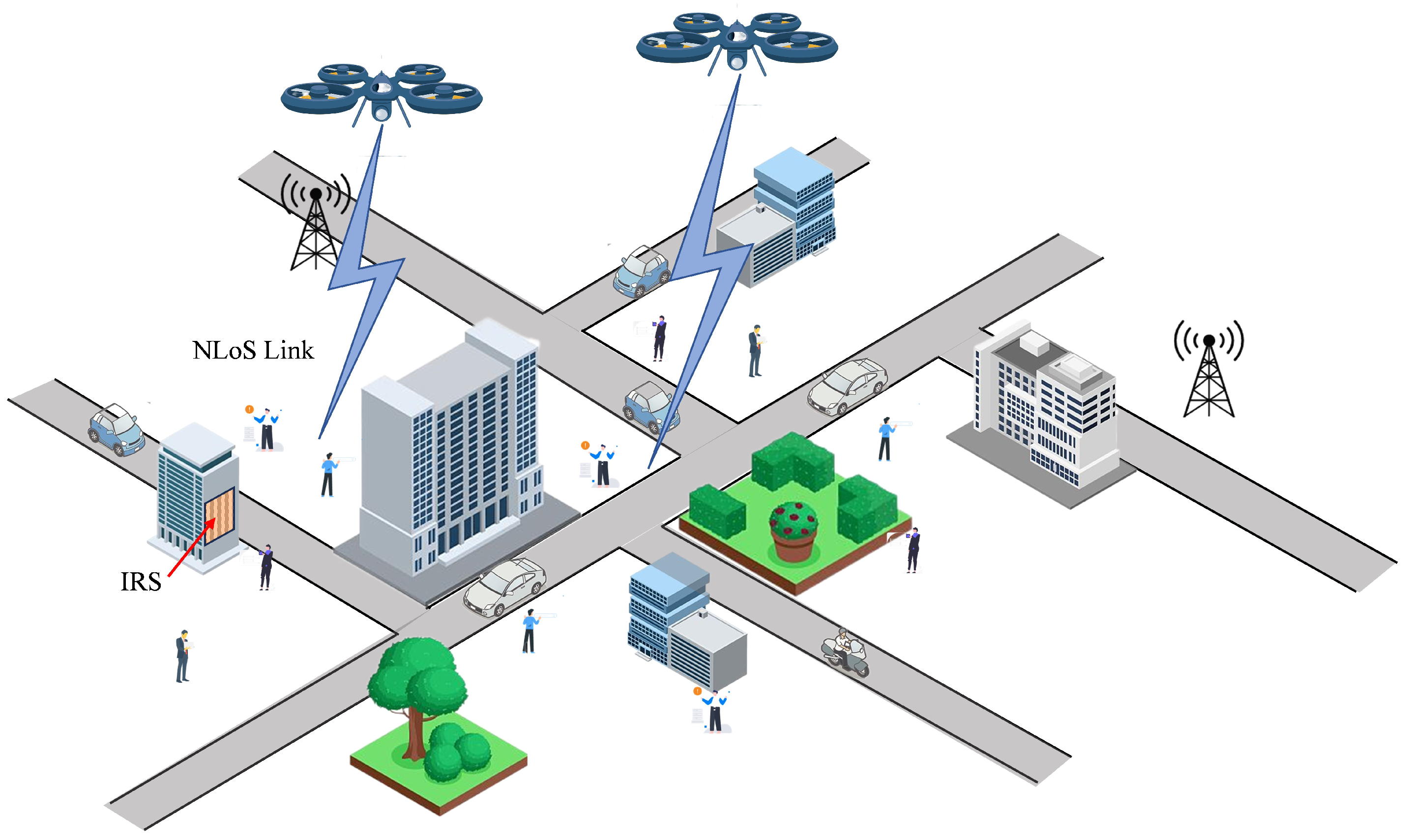
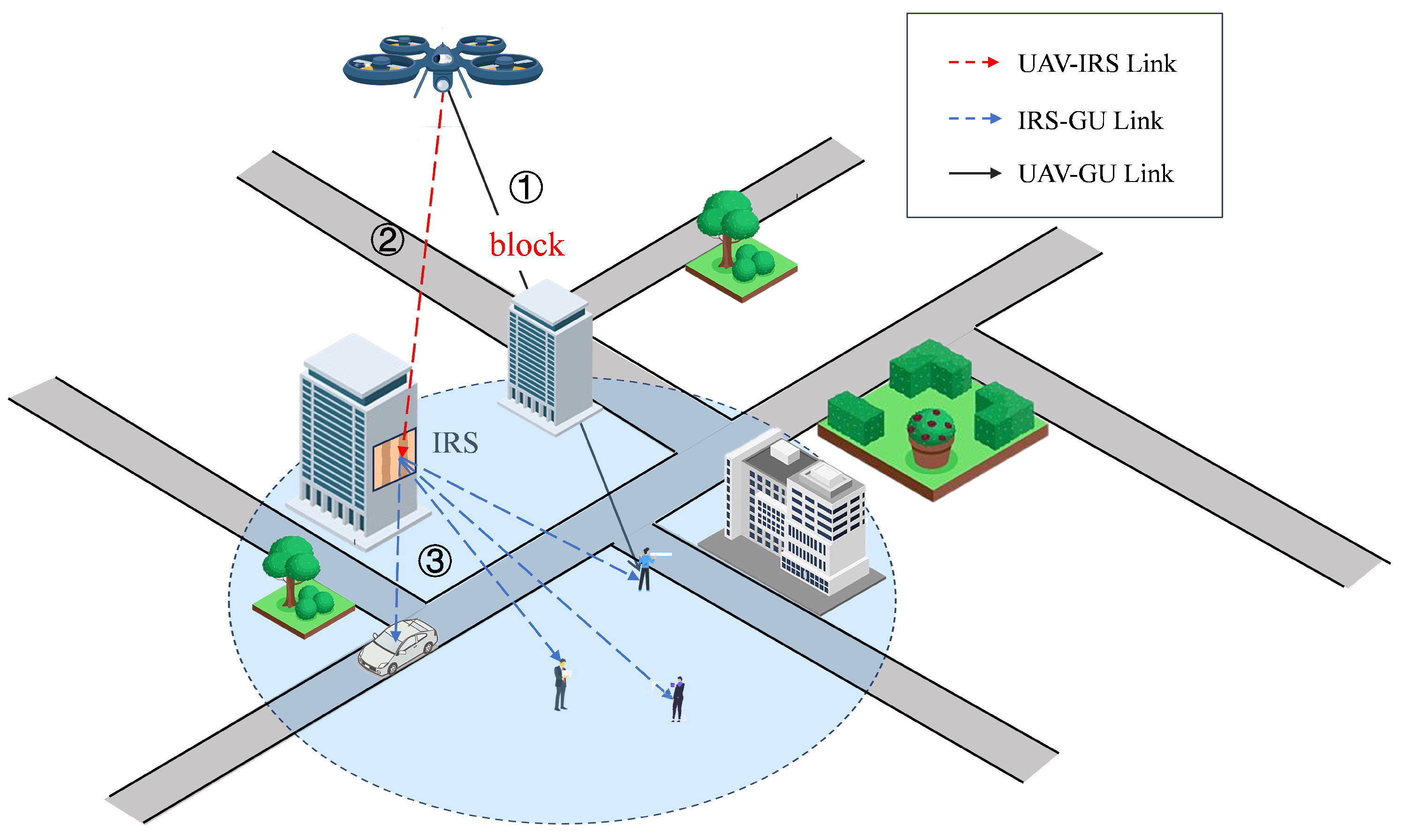
  • Signal blocking: In practical applications, the air-to-ground link is more likely to be blocked by territorial obstacles when UAVs fly at low altitudes in complicated environments.
Motivated by the above advantages and challenges, this paper considers a multi-cell cellular network in which UAVs act as aerial base stations to expand coverage and improve communication quality for edge GUs at a long distance. Furthermore, IRSs are deployed on the surface of ground buildings to reflect the UAVs’ signals to GUs.
For GUs, various users have different transmission rate requirements. Some GUs request high-latency-sensitivity services such as virtual reality and Internet of Vehicles (IoV), while others only request fundamental data computing services. In order to improve service efficiency, multicast channels with fixed transmitters have been extensively studied in wireless communications [2]. The capacity of a multicast channel is determined by the data rate of the GU with the worst channel quality in order for all users to successfully decode the common information from the transmitter. On one hand, the transmission rate is constrained if all the edge GUs are considered as one multicast group, which leads to more energy consumed by UAVs for hovering and transmission. On the other hand, when the UAV communicates with each GU in unicast mode, a higher transmission rate can be guaranteed. However, the UAV will consume more energy to travel longer distances. In order to trade off the two schemes, the GUs are divided into multiple multicast groups based on the transmission rate requirement in this paper. As a result, the average throughput of the entire system is improved since the transmission rate of each multicast group is determined by the GU with the worst channel condition within the group. UAVs can act as mobile transmitters [2] and leverage Orthogonal Frequency Division Multiple Access (OFDMA) technology to achieve multicast communication, thereby reducing energy consumption while overcoming user bottlenecks.
In contrast to conventional fixed GBSs, UAVs can adjust their positions horizontally and vertically over time, thus improving the wireless channel quality of users with different locations and transmission rate requirements. Therefore, optimizing the deployment location and trajectory of UAVs has become an important topic. The majority of current research focuses on optimizing UAV flight trajectory with a fixed altitude, ignoring the impact of NLoS links when UAVs fly at a low altitude. In terms of vertical altitude, for GUs with high transmission rate requirements, UAVs can appropriately shorten the communication link distance, thus increasing link capacity or saving transmit power. However, as shown in Figure 1, the lower the UAV’s altitude is, the more dominant the NLoS link will be [3]. Signals emitted by the aerial base station and received by the UAV propagate through the LoS link until reaching the urban environment, where additional loss is incurred due to shadowing and scattering caused by obstacles, such as buildings. Therefore, the 3D trajectory optimization problem needs to be tackled to design the optimal altitude over time.
In summary, this paper investigates the joint optimization problem of UAV 3D trajectory and power allocation in edge regions in a multi-UAV multicast network. GUs are categorized into multiple multicast groups, and each UAV serves one group at a time slot. The objective of this paper is to minimize the energy consumption of UAVs. To achieve this goal, GUs are first divided into different multicast groups depending on the relative distances and transmission rate requirements. This grouping issue is resolved by the K-medoids algorithm [4,5]. Next, it is important to find the 3D trajectory and power allocation that minimize UAVs’ energy consumption. This is known as an NP-hard problem because it involves coupled optimization variables, such as the UAVs’ association with the multicast group, the transmission power, the UAV data rate, and the UAV trajectory. The problem also consists of several non-convex constraints. Since multiple UAVs are considered in the system and each UAV needs to learn a policy, we utilize multi-agent deep reinforcement learning (MADRL) to solve the problem. MADRL can address the problem that the environment becomes non-stationary from the perspective of any individual agent with each agent’s policy updated [6]. For each agent, the Deep Deterministic Policy Gradient (DDPG) algorithm is applied which can learn policies in high-dimensional and continuous action spaces [7]. The main contributions in this paper are summarized as follows:
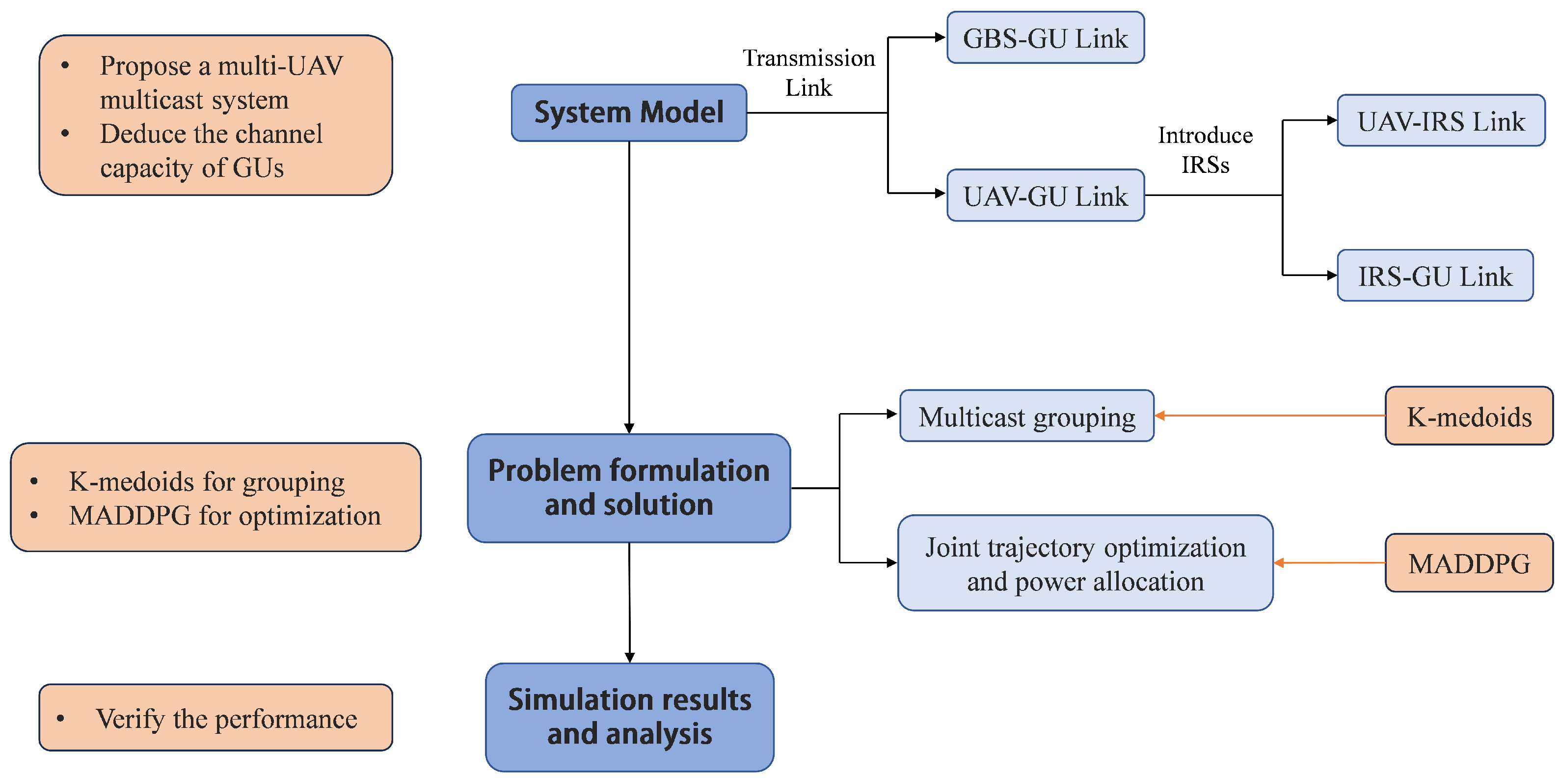
  • We propose a multi-UAV multicast system assisted by IRSs in which we formulate the multicast grouping problem and an optimization problem aiming to minimize the UAVs’ energy consumption.
  • We utilize the K-medoids algorithm [4,5] to solve the multicast grouping problem, and the MADRL framework is employed to efficiently obtain the optimal 3D trajectory and power allocation scheme and eliminate the non-stationarity of multi-agent training.
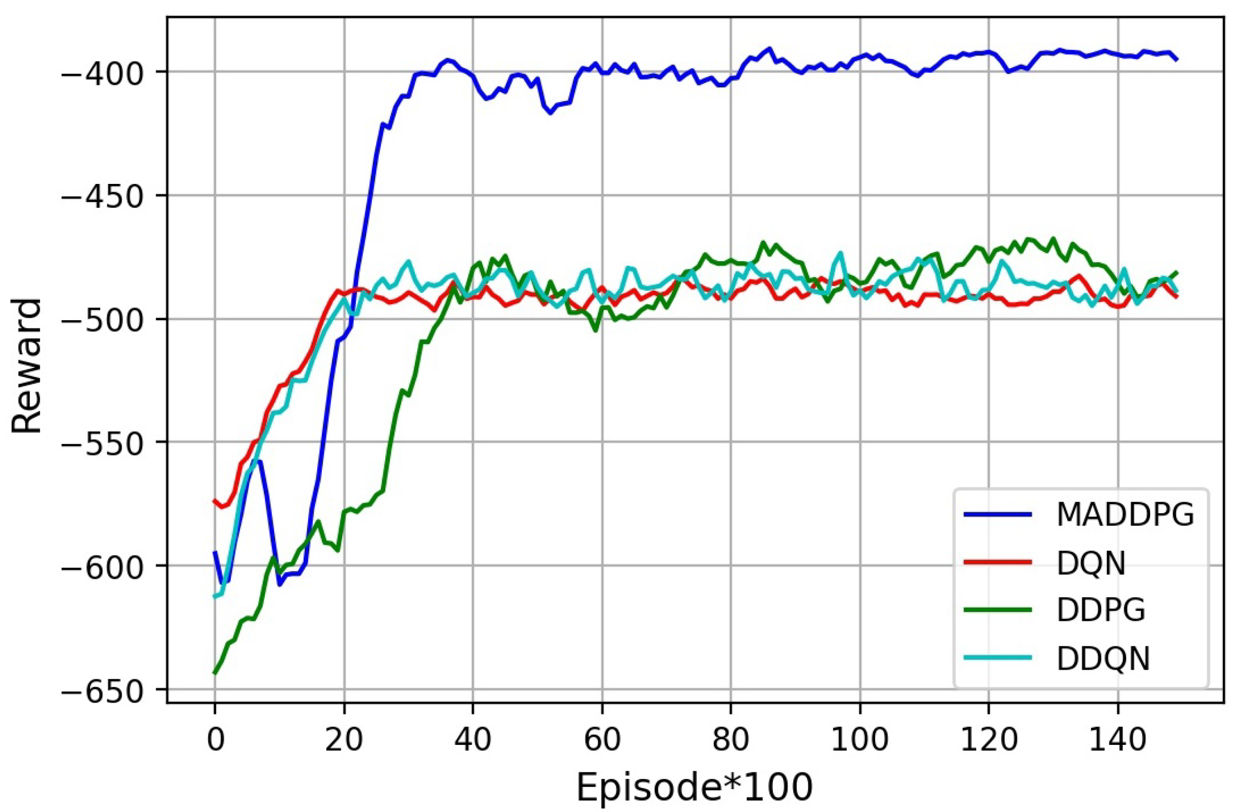
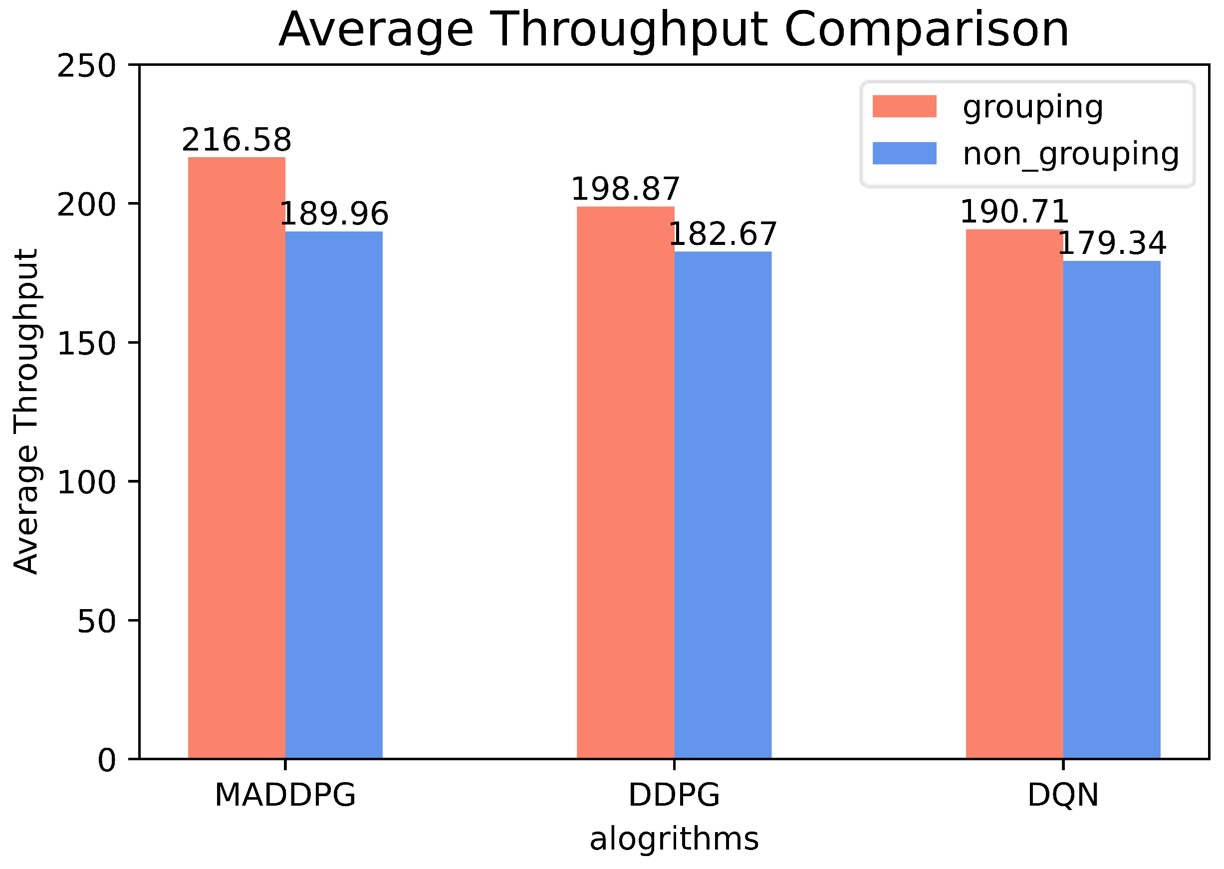
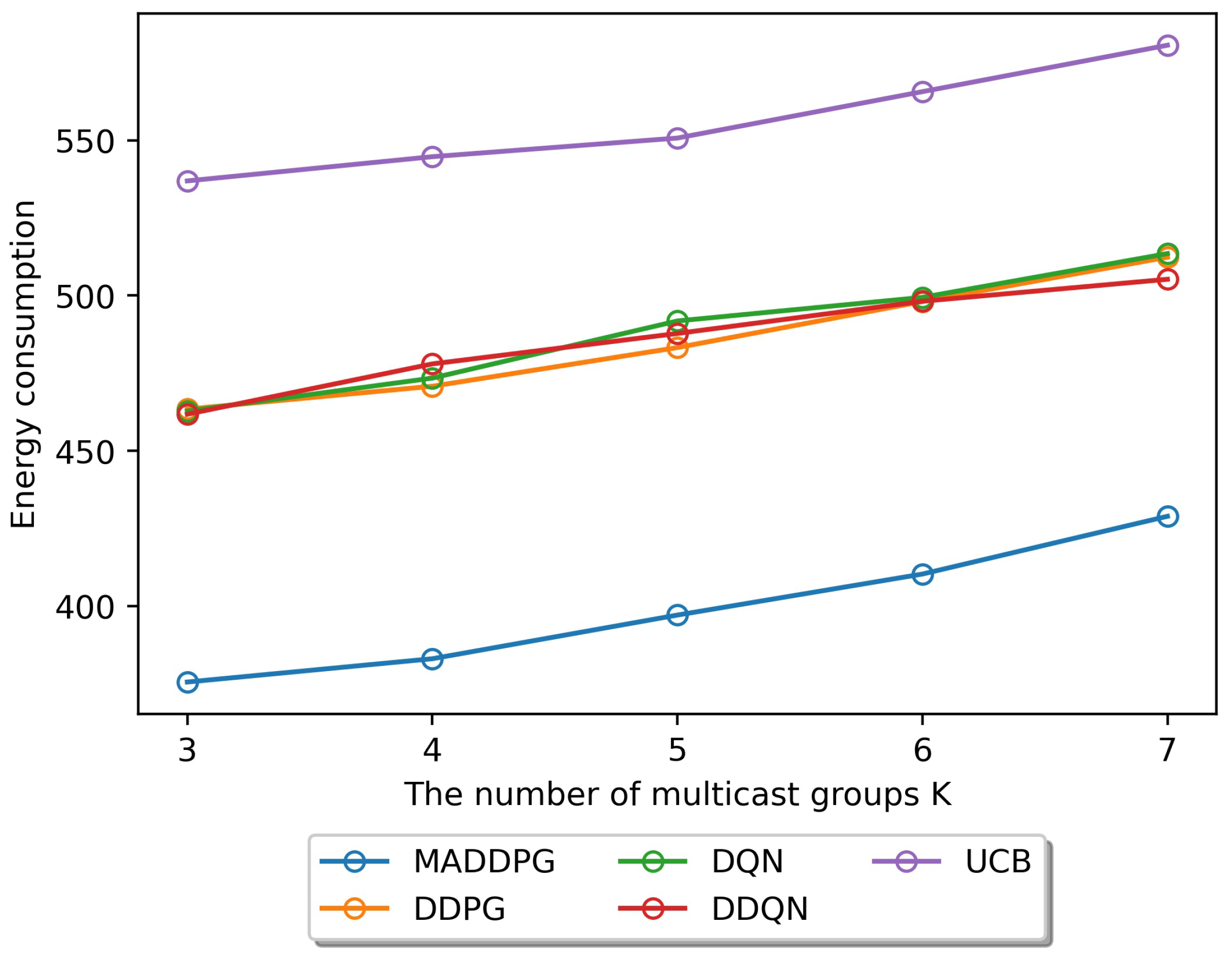
  • The performance can be evaluated by the provided simulation results. We verify that the proposed system can improve the average throughput, and the MADDPG algorithm can reduce the energy consumption of UAVs effectively compared to traditional DRL methods.
The rest of the paper is organized as follows. The literature review is presented in Section 2. Section 3 introduces the system model. Section 4 states the problem description and formulates the optimization objective. Section 5 illustrates the solution, including the grouping algorithm and the optimization algorithm. The simulation results are discussed in Section 6. Finally, Section 7 concludes this paper. The methodology is shown in the following Figure 2.

2. Related Works

In light of the challenges mentioned in Section 1, we investigated some of the literature on UAVs serving as aerial base stations in wireless communication systems. The literature can be reviewed from two perspectives: the problem statement and the optimization methods.
As for the problem statement, Deng et al. [8] investigated UAVs as aerial base stations to multicast public information to GUs and proposed a machine learning method to jointly optimize the multicast grouping and trajectory planning scheme. However, they solely considered a single-UAV network. Chen et al. [9] studied multiple UAVs as aerial base stations to enhance the coverage of cellular networks and proposed a decentralized joint trajectory and power control (DTPC) algorithm to minimize the UAVs’ overall energy consumption. Heuristic algorithms were proposed to formulate the trajectory optimization problem to minimize the total travel time of the UAVs in the multi-cell network in [10,11], where UAVs are employed as flying base stations to serve GUs in collaboration with GBSs. However, none of the above papers considered the multicast grouping problem based on user features or a situation in which the UAV-GU communication link may be blocked in practical low-altitude environments. In [12,13,14,15,16,17], intelligent reflection surfaces (IRSs) were introduced into UAV systems to assist the transmission between UAVs and GUs. Nguyen et al. [18] deployed IRSs to combat air-to-ground (A2G) blockage events and derived closed-form expressions for Signal-to-Interference-Plus-Noise-Ratio (SINR) distributions. The literature shows that IRSs can reduce blockage effectively in the UAV-GU communication link.
As for optimization methods, heuristic algorithms are typically used to solve the trajectory optimization problem. In [10,11], a set of local search heuristic algorithms was proposed considering the curse of dimensionality problem. Xue et al. [19] proposed a heuristic algorithm based on alternating descent and successive convex approximation (SCA) to solve a joint 3D location and transmit power optimization problem. However, typical heuristic algorithms are more suitable for static optimization problems without taking historical data into consideration. In [20], the authors formulated the problem as Budgeted Multi-Armed Bandits (BMABs) to optimize the UAV trajectory and minimize battery consumption and used two Upper Confidence Bound (UCB) BMAB schemes to tackle the issue. Nowadays, with the development of artificial intelligence technology, more and more researchers use machine learning techniques to solve optimization issues. The interaction between the agent and the environment in reinforcement learning (RL) is more similar to the mechanism by which UAVs make decisions based on the observation. The Double Deep Q-Network (DDQN) and DDPG algorithms were utilized in [12] to solve the UAV trajectory optimization problem in the IRS-assisted UAV system. Fan et al. [21] proposed a novel multi-agent DRL method with global–local rewards for UAVs’ dynamic trajectory planning and data offloading decisions. In the multi-agent case, the intricate process of interactions between agents makes the environment constantly and dynamically changing. The non-stationarity will reduce the stability of the algorithm.
In summary, very little of the literature focuses on both the multicast grouping issue based on users’ characteristics and the joint optimization problem. Since machine learning techniques have become the new research trend, MADRL can be utilized to handle the issues in traditional DRL methods.

3. System Model

3.1. System Model

We consider a multi-cell cellular network, as shown in Figure 3, where multiple UAVs serve as aerial base stations to provide access to edge GUs that cannot be effectively served by GBSs. The set of edge GUs is represented by N = { n | n = 1 , 2 , , N } . The GUs are divided into K multicast groups, with different transmission rate requirements for each group. The set of multicast groups is denoted as K = { k | k = 1 , 2 , , K } . N k represents the number of GUs within the kth multicast group, satisfying N = k K N k , N i N j = , i j N , which means there’s no overlap between groups. The location of the ith GU is denoted as L i G U = ( x i , y i ) , i N , and the transmission rate is denoted as γ i . The two characteristics are used as metrics to classify multicast groups. When grouping has been completed, in order to satisfy the transmission rate requirement of all users in each group, the transmission rate requirement of the kth group is denoted as γ k = max i N k γ i .
UAVs fly within the multi-cell edge region and serve terrestrial multicast groups. Let T = { t | t = 1 , 2 , , T } denote the set of service time slots, which is also termed as an episode. The length of each time slot is defined as Δ t . Assume that there are U UAVs, and the set of UAVs is represented by U = { u | u = 1 , 2 , , U } . L u , t U A V = ( x u , t , y u , t , h u , t ) denotes the trajectory of the uth UAV at time slot t. Each multicast group is served by the closest UAV at each time slot. If the closest UAV is already occupied by its closest group, the second closest UAV will work. We assume that there are sufficient UAVs to ensure that each multicast group is served by one UAV at each time slot.
Meanwhile, in order to solve the signal-blocking problem when UAVs fly at low altitudes, an IRS is deployed on the surface of the building near each multicast group to avoid the NLoS link between UAVs and GUs. Denote R = { r | r = r 1 , r 2 , , r K } as the set of IRSs. r k is the IRS corresponding to the kth multicast group, and its location is defined as L r k I R S = ( x r k , y r k , h r k ) . For the IRS, we assume that a uniform planer array (UPA) consists of M c × M r passive reflection units (PRU). Each PRU can passively change its phase-shift with an independent reflection coefficient: r r k , m c , m r = a e j θ r k , m r , m c , k K ; m r 1 , 2 , , M r ; m c 1 , 2 , , M c where a [ 0 , 1 ] is the fixed reflection loss of the IRS and θ r k , m r , m c [ π , π ) is the phase shift inserted at PRU ( m r , m c ) [12].

3.2. Transmission Model
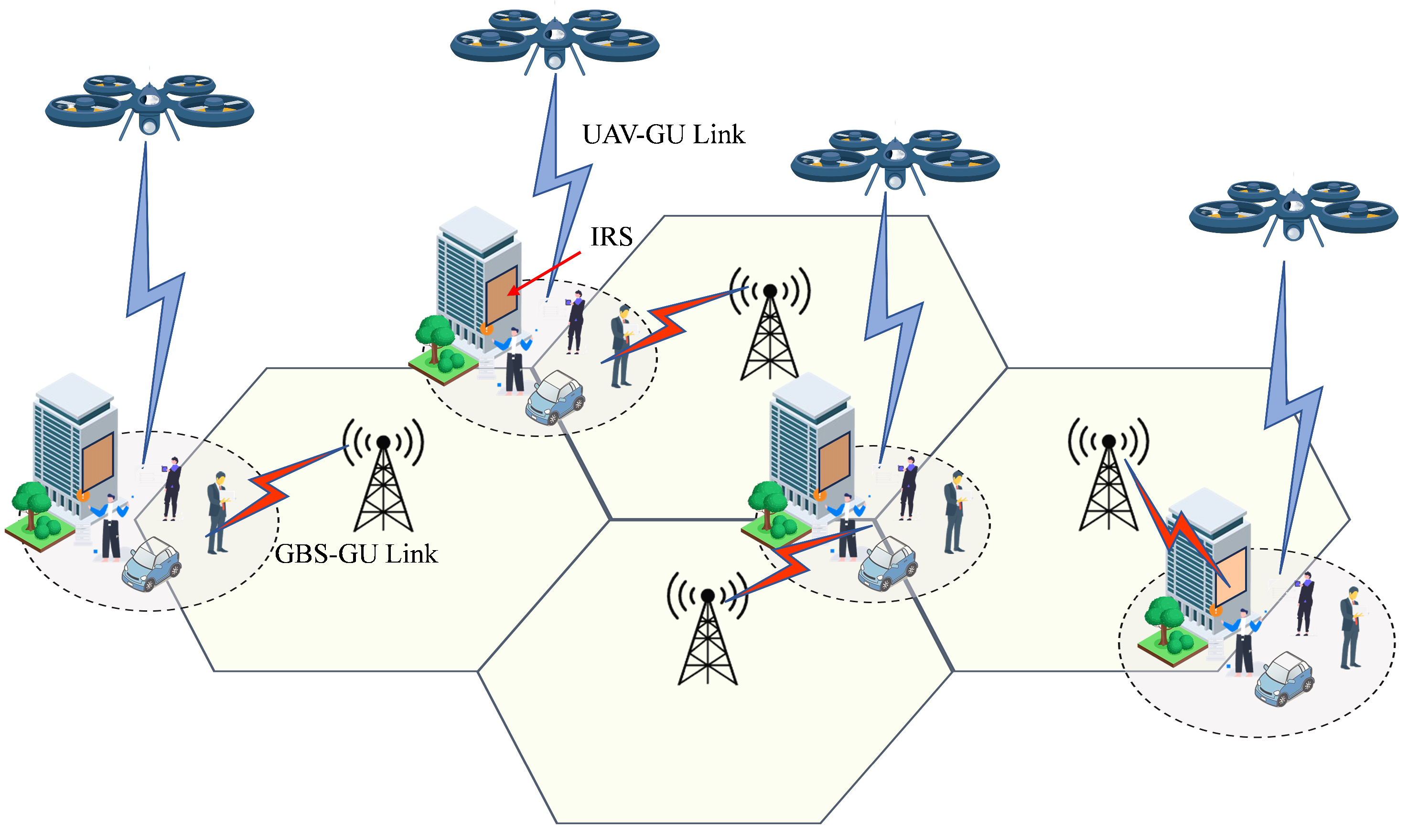
The transmission model consists of two parts: the GBS-GU link and the UAV-GU link. UAVs provide supplemental services when the GBS is unable to meet the needs of the edge GUs. The service procedure of the uth UAV for the multicast group is shown in Figure 4. The uth UAV serves the kth multicast group at time slot t, during which other UAVs serve the other multicast groups. Over time, the UAV continues to fly to serve the next multicast group at time slot t + 1 .

3.2.1. GBS-GU Link

In the GBS-GU link, the ith GU is served by the closest GBS. The GBS-GU link channel is assumed according to [22], where it can be assumed to be a fading channel with a distance-dependent path loss with the exponent δ 2 and an additional random term ζ g , i E x p ( 1 ) accounting for small-scale fading. As a result, the received signal-to-noise-ratio (SNR) at the ith GU from the GBS can be expressed as
S N R i G = γ i G = G G P G g 0 σ 2 ( r g , i 2 + H G 2 ) δ / 2
where i N ; G G , H G , r i , and P G denote a fixed antenna gain, the height of the GBS, the distance between the ith GU and the GBS, and the transmit power of the GBS, respectively; g 0 = ( c 4 π f c ) 2 denotes the average channel power gain at a reference distance of d 0 = 1 m ; and σ 2 denotes the noise power. According to Shannon’s theorem, the transmission rate from the GBS to the ith GU is calculated as
R g , i = B log 2 ( 1 + γ i G ζ i )
where B is the total transmission bandwidth.

3.2.2. GBS-GU Link Outage Probability
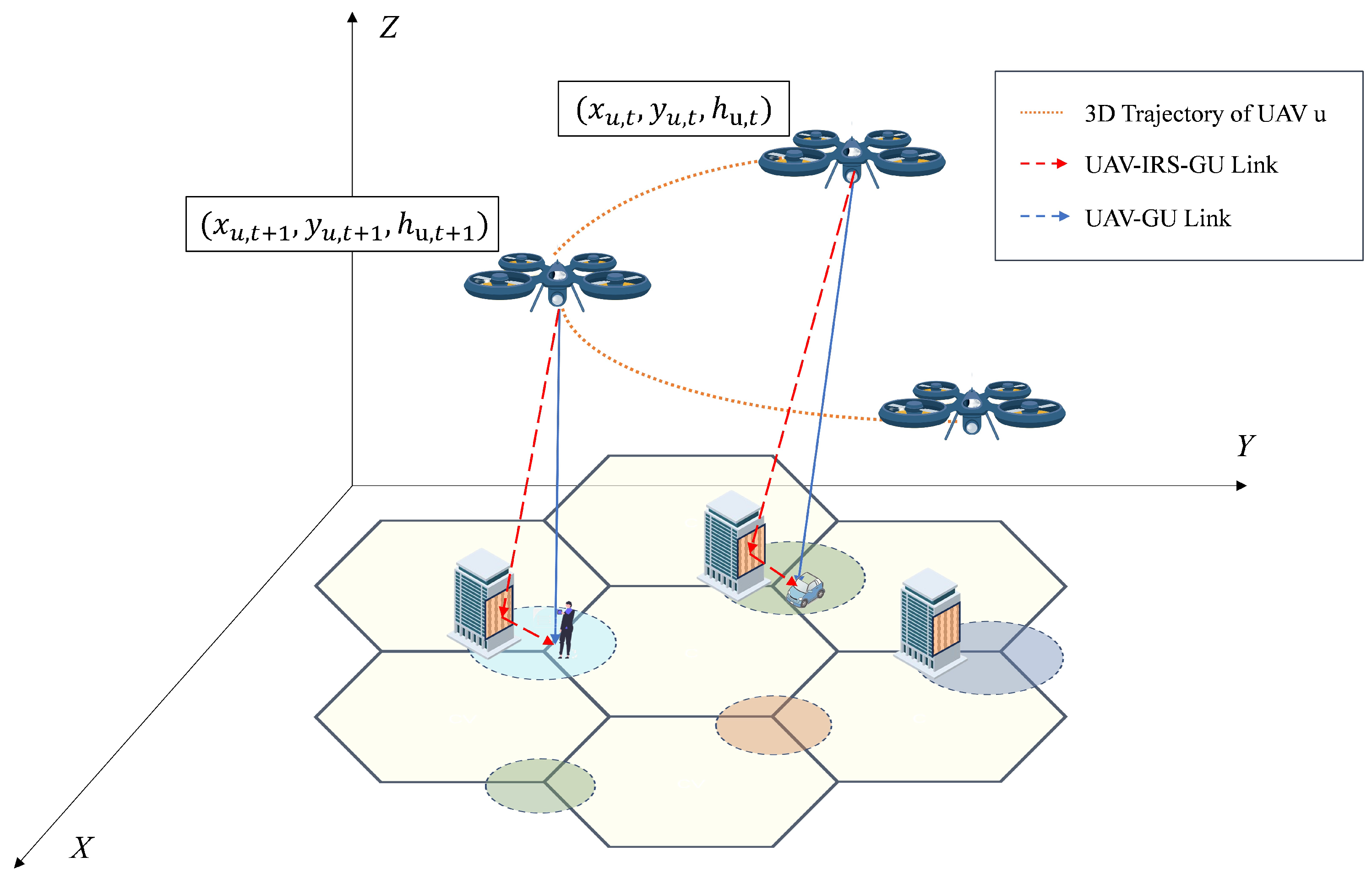
An outage occurs when the GBS is unable to meet the ith GU’s transmission rate requirement γ i because of the small-scale fading between the GBS and GUs. The outage probability is expressed as
P g , i = P r { R g , i < γ i } = P r { B log 2 ( 1 + γ i G ζ g , i ) < γ i } = P r { ζ g , i < 2 γ i / B 1 γ i G } = 1 e x p ( 2 γ i / B 1 γ i G )

3.2.3. UAV-GU Link

When GBSs are unable to provide reliable communication to the ith GU, the service is provided by UAVs in the multicast mode. In order to avoid NLoS links induced by shadowing and scattering caused by building complexes in urban environments, IRSs are introduced to reflect UAV-GU signals. As shown in Figure 5, the UAV-GU link can be replaced by the two UAV-IRS and IRS-GU links, both of which are LoS connections.
Similar to [22], we assume the corresponding antenna gain in direction ( α , β ) as
G U ( α , β ) = G 0 / Θ U 2 , Θ U α Θ U , Θ U β Θ U g 0 0 , o t h e r w i s e
where G 0 = 30000 2 2 ( π 180 ) 2 2.2846 and Θ U ( 0 , π 2 ) . Thus, the ground coverage region of the UAV’s antenna main lobe corresponds to the disk region with a radius r u , t = h u , t tan Θ U that is centered on the projection of the UAV on the ground. Determining the beamwidth Θ U , the coverage radius can be adjusted by changing the UAV’s altitude h u , t so that the GUs are located within the coverage area of the UAV.
When the signal reaches the urban environment, obstacles, such as building complexes, cause additional losses in the UAV-GU link. Define the outage probability at time slot t of the uth UAV with the ith GU in the kth multicast group as:
p u , i , t = P N L o S = 1 1 1 + C e x p D arctan ( h u , t d u , i , t ) C
where i N k , k K ; d u , i , t = ( h u , t ) 2 + ( x i x u , t ) 2 + ( y i y u , t ) 2 is the distance between the ith GU and the uth UAV’s at time slot t; arctan ( h u , t d u , i , t ) denotes the elevation angle of the UAV to the ith GU; and D and C are constant values depending on the environment.
On one hand, when the UAV-GU link is unblocked, and assuming free space fading channel gain, the channel gain between the uth UAV and the ith GU at time slot t can be expressed as
g u , i , t L o S = g 0 d u , i , t δ
where δ = 2 and g 0 = ( c 4 π f c ) 2 . On the other hand, when the UAV-GU link is blocked, IRS is applied, as shown in processes ② and ③ of Figure 5.
(1)
UAV-IRS link
At time slot t, let ω 1 , u , r k , t = | x r k x u , t | d u , r k , t , ω 2 , u , r k , t = | y r k y u , t | d u , r k , t , and ω 3 , u , r k , t = | h r k h u , t | d u , r k , t denote the cosine and sine of the horizontal angle of arrival (AoA) of the signal at the IRS r k from the uth UAV and the sine of the vertical AoA of the signal at the IRS r k , respectively [12]. d u , r k , t = ( h u , t h r k ) 2 + ( x u , t x r k ) 2 + ( y u , t y r k ) 2 denotes the Euclidean distance between the uth UAV and IRS r k near the kth multicast group at time slot t. The channel gain between the uth UAV and IRS r k at time slot t can be expressed as
g u , r k , t = g 0 d u , r k , t δ · Ω u , r k , t
where d r and d c denote the length and the width of each UPA, respectively; Ω u , r k , t = [ 1 , e j 2 π λ d r ω 1 , u , r k , t ω 3 , u , r k , t , , e j 2 π λ ( M r 1 ) d r ω 1 , u , r k , t ω 3 , u , r k , t ] T   [ 1 , e j 2 π λ d c ω 2 , u , r k , t ω 3 , u , r k , t , , e j 2 π λ ( M c 1 ) d c ω 2 , u , r k , t ω 3 , u , r k , t ] T represents the reflecting array response vector of the IRS [23].
(2)
IRS-GU link
Similar to the UAV-IRS link, we define the cosine and sine of the horizontal angle of arrival (AoA) of the signal at the ith GU from the IRS r k as ω 1 , r k , i = | x r k x i | d r k , i and ω 2 , r k , i = | y r k y i | d r k , i . ω 3 , r k , i = h r k d r k , i is the sine of the vertical AoA. d r k , i = ( h r k ) 2 + ( x i x r k ) 2 + ( y i y r k ) 2 denotes the Euclidean distance between the IRS r k and the ith GU in the k multicast group. The channel gain from the IRS r k multicasting to the ith GU is
g r k , i = g 0 d r k , i δ · Ω r k , i
where Ω r k , i = [ 1 , e j 2 π λ d r ω 1 , r k , i ω 3 , r k , i , , e j 2 π λ ( M r 1 ) d r ω 1 , r k , i ω 3 , r k , i ] T   [ 1 , e j 2 π λ d c ω 2 , r k , i ω 3 , r k , i , , e j 2 π λ ( M c 1 ) d c ω 2 , r k , i ω 3 , r k , i ] T .
(3)
IRS-Assisted UAV-GU link
The channel gain of the UAV-GU link assisted by the IRS r k is given by
g u , i , t I R S = a ( g r k , i ) T · M r k , t · g u , r k , t
where M r k , t = d i a g ( e j θ r k , 1 , 1 t , , e j θ r k , m r , m c t , , e j θ r k , M r , M c t ) denotes the IRS reflection phase coefficient matrix.
Combining (5), (6) and (9), the achievable average channel gain and SNR at the ith GU are expressed as
g u , i , t = ( 1 p u , i , t ) g u , i , t L o S + p u , i , t g u , i , t I R S
S N R u , i , t U = γ u , i , t U = G U P u , t g u , i , t σ 2
where P u , t is the uth UAV’s transmit power at time slot t and σ 2 denotes the thermal noise power, which is linearly proportional to the allocated bandwidth [24].
We utilize OFDMA technology for multicasting. The transmission rate for the kth multicast group at time slot t is decided by the GU with the worst channel quality within the group:
R u , k , t = min i N k B | N k | l o g 2 ( 1 + γ u , i , t U )
where | N k | denotes the number of GUs in the kth multicast group, and B is the total transmission bandwidth. According to (2), (3) and (12), the channel capacity of the ith GU in the kth multicast group can be calculated by
R i , t = ( 1 P g , i ) R g , i GBS - GU + P g , i R u , k , t UAV - IRS - GU , i N k
Therefore, the average throughput of the system is
t h r o u g h p u t = i N k , k K R i , t

4. Problem Formulation

4.1. Multicast Grouping

Our goal is to optimize the 3D trajectory of the UAVs based on the transmission rate requirements of different GUs while minimizing energy consumption. First, we divide the N GUs into K multicast groups based on the characteristics of the GUs. We assume that the GUs remain static during the grouping procedure. The characteristics of the ith GU is defined by ϕ i = { L i G U , γ i } , i N , which denotes the location and transmission rate requirement, respectively. Let x i , k { 0 , 1 } indicate the correspondence between the GUs and multicast groups. x i , k = 1 indicates that the ith GU belongs to the kth multicast group. The multicast grouping problem can be formulated as
P 1 : min X , ψ k = 1 K i = 1 N x i , k ϕ i ψ k 2
s . t . x i , k { 0 , 1 } , i N
k = 1 K x i , k = 1 , i N
i = 1 N x i , k S , k
where ψ k is the characteristics of the GU selected as the kth multicast group’s center. The constraints in (17) guarantee that a GU can only be in one multicast group. The constraints in (18) ensure that the number of GU within a group cannot exceed S.

4.2. Trajectory Optimization and Resource Allocation

4.2.1. UAV Energy Consumption

UAVs are mostly battery-powered with limited energy storage, so we aim to minimize the energy consumption of UAVs. At time slot t, the energy consumption of a UAV consists of the energy used to transmit signals to GUs and the energy for UAVs flying in the air. The hovering energy consumption can be neglected compared to both of them [9].
First, the delay of transmission from the uth UAV to the kth multicast group at time slot t can be denoted as T u , k , t = S u , k , t R u , k , t ,   T u , k , t Δ t , where S u , k , t is the size of the transmission data; the transmission should be finished within the time slot. Therefore, the transmission energy consumption at time slot t can be calculated as
E u , m , t = P u , t T u , k , t = P u , t S u , k , t R u , k , t
Then, according to [12], the flying propulsion consumption at time slot t is calculated as
E u , f , t = P 0 ( 1 + 3 v u , t 2 V m a x 2 U t i p 2 ) + P 1 v h , u , t Δ t
where P 0 is the blade power; U t i p is the tip speed of the rotor; P 1 is the descending/ascending power; V m a x is the achievable maximal speed of UAVs; v u , t = ( v x , u , t , v y , u , t , v h , u , t ) denotes the normalized speed of the uth UAV at time slot t, where v u , t   1 and 1 v x , u , t , v y , u , t , v h , u , t 1 . Therefore, the location of the uth UAV at time slot t + 1 is
L u , t + 1 U A V = L u , t U A V + v u , t Δ t
Furthermore, as for obstacle avoidance, we consider the collision between the UAVs. UAVs have to keep a minimum distance from each other at any time. In other words,
L u , t U A V L u , t U A V 2 d m i n 2 ; u u U , t
where d m i n is the minimum distance UAVs should keep between each other.
In order to minimize the energy consumption in (19), the transmission rate R u , k , t needs to be maximized. The channel gain g u , i , t also needs to be maximized according to (11) and (12). The probability of the NLoS link P N L o S in (5) is a monotonically decreasing function as the UAV’s altitude increases. When the altitude h u , t is elevated, its elevation angle to the GU increases, and the probability that the LoS link is dominated increases. However, as the UAV is elevated and the distance between the UAV and the GU increases, the channel gain g u , i , t L o S decreases. Therefore, in order to achieve the goal of minimizing energy consumption, altitude optimization needs to be tackled.

4.2.2. Joint Trajectory Optimization and Power Allocation Problem

Based on the above analysis, to minimize the total energy consumption of multiple UAVs, the joint optimization problem about the 3D trajectory and power allocation can be formulated as
P 2 : min V , P t = 1 T u = 1 U E u , m , t + E u , f , t
s . t v u , t   1 ;
P u , t P m a x ;
T u , k , t Δ t ;
L u , t U A V L u , t U A V 2 d m i n 2 ; u u U , t ;
where V = { v u , t | u U } indicates the speed of the UAVs and P = { P u , t | u U } indicates the transmit power of the UAVs. The constraints in (24) ensure the normalized speed, and (25) guarantees that the UAV’s transmit power cannot exceed the maximal power. The constraints in (26) ensure that the data transmission at time slot t must be completed within it. The constraints in (27) guarantee that individual UAVs do not collide during their respective flights.

5. Proposed Solution

5.1. K-Medoids for Multicast Grouping

We utilize K-medoids, an improved algorithm of the K-means clustering algorithm, to solve the multicast grouing problem P 1 . In the K-medoids algorithm, when given the location of the cell edge GUs and the number of multicast groups K, we can find the corresponding multicast group centers and edge GUs contained in each multicast group [4,5].
First, the K medoids are randomly initialized, and the iteration is set as t = 0 . Subsequently, the medoids are continuously updated in iterations. When the medoids and their characteristics ψ k are given, P 1 can be simplified as
min X k = 1 K i = 1 N x i , k ϕ i ψ k 2 , s . t . ( 16 ) ( 17 ) ( 18 )
Problem (28) can be solved by the branch and bound method [5]. In iteration t + 1 , the medoid of each multicast group is updated to be the member point with the smallest criterion function, which is the distance of the user characteristics between one member point and the other member points. The medoid in the kth multicast group is updated as
ψ k t + 1 = arg min ϕ i t ϕ i t ϕ j t 2 , i , j m k ; i j
where m k denotes the set of members in the kth group. Repeat the above process until all the medoids do not change. The algorithm outputs the optimal medoids’ location L k M G = ( x k , y k ) , k K and the GUs’ location in the kth multicast group L m k G U = ( x i , y i ) , i N k , k K .
The specific algorithm is shown in Algorithm 1.
Algorithm 1 Constrained K-medoids
Input: 
GUs’ location L GU , number of groups K
Output: 
optimal grouping strategy X
1:
Initialization: set iteration t = 0 and randomly initialize ψ k 0 .
2:
for the iteration t = 1 , 2 , 3 ,
3:
      Given ψ k t , solve (28) to find current optimal grouping strategy X t .
4:
      Update multicast group medoids ψ k t + 1 using (29).
5:
until medoids no longer change.

5.2. MADDPG for Optimization Problem

After solving the grouping problem, the joint trajectory optimization and power allocation problem is solved based on the best grouping strategy. In this section, we propose solving P 2 with the MADDPG algorithm.
Each UAV acts as an agent that interacts with the environment over T time slots. At time slot t, an action a t is generated based on the state s t of the environment around the agent, and a reward r t is obtained for judging the action a t generated in the current state. The goal of each agent is to train a policy π that can generate the action a t that makes the reward r t the highest based on the current state. Subsequently, at time slot t + 1 , the state s t transits into a new state s t + 1 due to the action a t , and the process is repeated till the end of an episode.

5.2.1. State, Action, and Reward

In order to solve P 2 with MADDPG, we define the state, action, and reward of each UAV, which acts as an agent at time slot t.
(1)
State
For each agent, the state includes information perceived from the environment based on which the agent determines its action and evaluates long-term rewards. Since the transmission rate is related to the distance between the UAV and GU, each agent’s perceived information includes the observed multicast groups and the locations of its member users along with the UAVs’ locations. Then, the state of the uth UAV can be formulated as
s u , t = [ L 1 , t U A V , L 2 , t U A V , , L M u , t U A V , L m 1 , t G U , L m 2 , t G U , , L m M k , t G U ]
which includes the locations of the M u closest neighbor UAVs that can be observed at the current time slot and the locations of GUs in the M k closest multicast group.
(2)
Action
In P 2 , we need to determine the speed and the power allocation of the UAV at time slot t. The action of the uth UAV can be formulated as
a u , t = [ v u , t , P u , t ]
where (24) and (25) are satisfied.
(3)
Reward
The reward function determines the objective of the RL problem. The objective function of P 2 is to minimize the energy consumption of the UAV, while the objective of RL is to maximize the reward. The reward of each agent can be set as negative energy consumption:
r u , t = ( E u , m , t + E u , f , t )

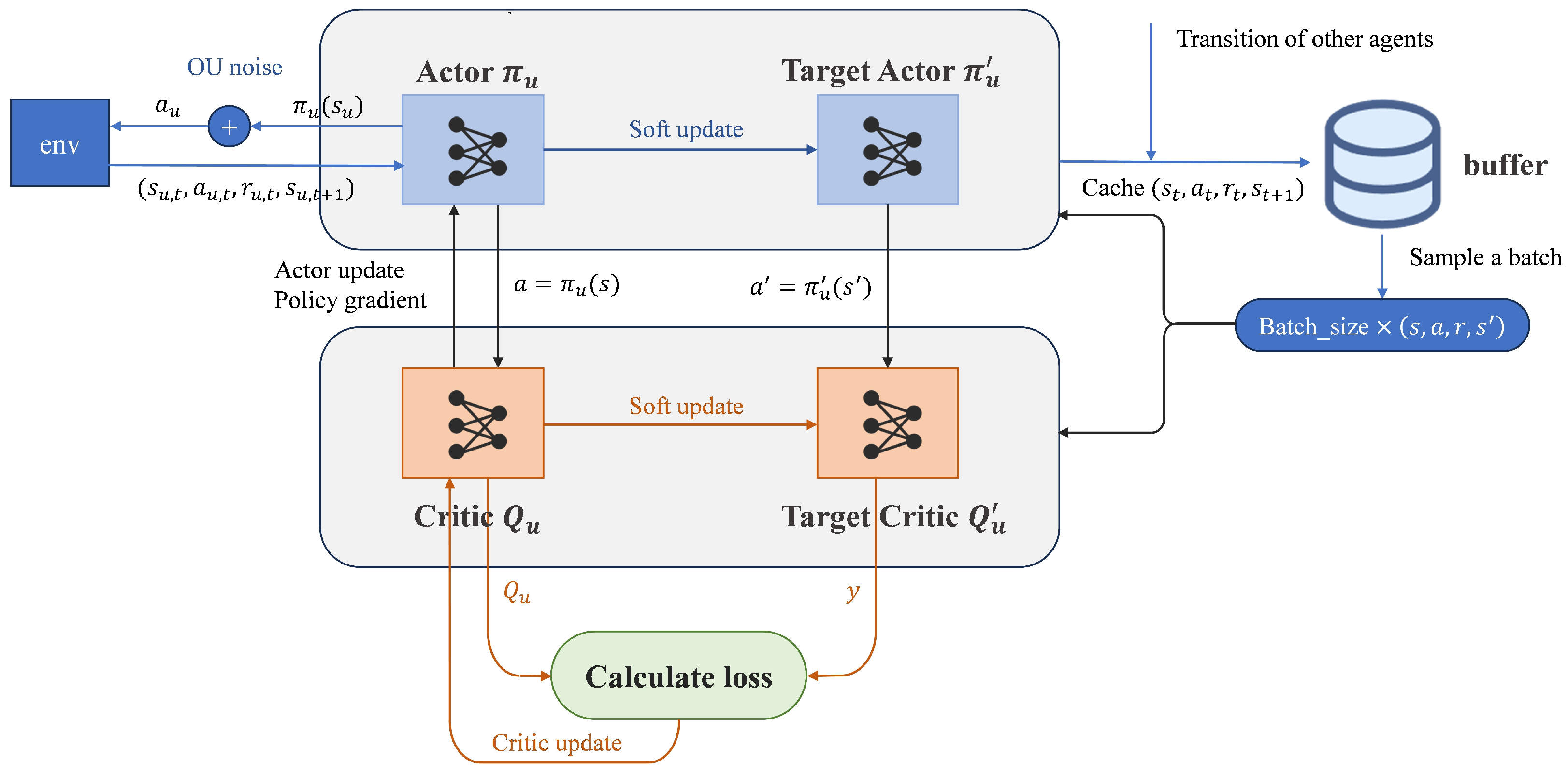
5.2.2. MADDPG Algorithm

The 3D trajectory and power allocation to be optimized in Problem P 2 are both continuous variables. DDPG, based on an actor–critic architecture, is able to learn a deterministic policy for continuous actions, which can directly output the optimal action. However, in the multi-agent case, if each agent only considers its own observations and actions to learn its own policy using DDPG, the environment will become non-stationary from the perspective of any individual agent. This is due to the fact that the policies of other agents are also constantly updated and changing, and the sampled data of the agent does not follow a consistent probability distribution.
Therefore, Ref. [6] proposed a framework of centralized training and decentralized execution, which allows the critic to obtain the policy information of other agents during the training process. Only local information is needed when applying the actor to make decisions. The framework is shown in Figure 6. On one hand, the centralized critics Q u that MADDPG trains for each agent use the observed states and actions of all agents as input. As a result, critics are able to capture changes in all agents’ policies, thus eliminating non-stationarity [9]. The Q-value computed by the critic Q u is used to update the corresponding actor’s policy network π u . On the other hand, when each agent is sufficiently trained, the actor can compute the policy independently based on the state, without the feedback of the critic and the state or action information of other agents. Hence, MADDPG facilitates fully decentralized execution. In general, MADDPG can be regarded as a centralized RL technique when training.
As shown in Figure 7, the training process of MADDPG includes data sampling, model training, and parameter updating. We define the state set, the action set, and the reward set from all of the agents as s t = { s 1 , t , s 2 , t , , s U , t } , a t = { a 1 , t , a 2 , t , , a U , t } , and r t = { r 1 , t , r 2 , t , , r U , t } , respectively. According to [9], setting a specific reward in (32) for each agent will lead to increasing training complexity, so we set the reward of each agent to be the cumulative reward of all agents, u = 1 U r u , t . The reward in (32) is changed to be
r u , t = u = 1 U ( E u , m , t + E u , f , t )
Each agent contains four networks during training. The actor network and target actor network share the same network architecture. The input is the current state s u , t of agent u, and the output is the action a u , t . The critic network has the same network architecture as the target critic network. The inputs are the states and actions of all the agents, and the output is the Q-value, which is defined as
Q u π ( s , a ) = E t = 0 γ t r u , t
where γ denotes the discount factor.
Let π = { π 1 , π 2 , , π U } denote the policies of U agents, which are fitted, respectively, by U actor networks parameterized by θ π = { θ 1 π , θ 2 π , , θ U π } . As shown in Figure 7, the parameters of the actor are updated by policy gradient, which is calculated as
θ u J ( θ u ) = E ( s , a ) D [ a u Q u π ( s , a ) | a u = π u ( s u ) θ u π u ( s u ) ]
where D represents the experience replay buffer. Each state transition ( s u , t , a u , t , r u , t , s u , t + 1 ) of agent u with other agents is stored in the buffer.
U critic networks are parameterized by θ Q = { θ 1 Q , θ 2 Q , , θ U Q } . The updating process of the critic is shown in Figure 7. The gradient descent method is used to minimize the following loss function
L ( θ u Q ) = E ( s , a , r , s ) D [ Q u π ( s , a ) y ] 2
where y = r u + γ Q u π ( s , a ) | a u = π u ( s u ) , Q u π and π u denote the target critic and the target actor, respectively. After the actor and critic are updated, we use a soft update to update the two target networks as
θ π τ θ π + ( 1 τ ) θ π θ Q τ θ Q + ( 1 τ ) θ Q
where τ is typically set as τ = 0.001 .
The specific steps are shown in Algorithm 2.
Algorithm 2 MADDPG for Optimization Problem
1:
Initialization: Randomly set θ π , θ π , θ Q , θ Q ; D = .
2:
for  episode = 1 to max - episode - num  do
3:
   Reset the environment, and receive initial state s = { s 1 , s 2 , , s U } .
4:
   for  t = 1 to max - episode - length T  do
5:
     for each agent u, select action a u = π u ( s u ) + noise .
6:
     Execute actions a = { a 1 , a 2 , a U } and observe reward r = { r 1 , r 2 , r U } and next state s .
7:
     Push ( s , a , r , s ) into replay buffer D .
8:
      s s .
9:
     if  length of D larger than given length  then
10:
        for  UAV agent u = 1 to U  do
11:
          Sample a random batch of S samples { ( s j , a j , r j , s j ) } j = 1 , , S from D .
12:
          Set y j = r u j + γ Q u π ( s j , a j ) | a u j = π u ( s u j ) .
13:
          Update critic θ u Q by minimizing the loss L ( θ u Q ) = 1 S j ( Q u π ( s j , a j ) y j ) 2 .
14:
          Update actor θ u π using the sampled policy gradient θ u π J ( θ u π ) 1 S j [ a u j Q π ( s j , a j ) | a u j = π u ( s u j ) θ u j π u ( s u j ) ] .
15:
        end for
16:
        Update target network parameters by θ π τ θ π + ( 1 τ ) θ π and θ Q τ θ Q + ( 1 τ ) θ Q .
17:
     end if
18:
   end for
19:
end for

6. Simulation Results

In this section, we simulate the performance of MADDPG in the multi-UAV multicast system, comparing it with DDPG, Deep Q-Network (DQN), DDQN, and a classical RL algorithm Upper Confidence Bound (UCB) designed for Budgeted Multi-Armed Bandits (BMABs) problems. This paper considers a three-dimensional space with four cellular cells, each equipped with a GBS at the center. A total of 100 GUs are randomly distributed in the targeted area. The GUs are determined whether or not they are served by a UAV acting as an aerial base station according to (3). The GUs are divided into five multicast groups according to their locations and transmission rate requirements. There are five UAVs to serve them, and the initial positions of the UAVs are set as ( 400 , 400 , 200 ) ,   ( 400 , 400 , 200 ) ,   ( 400 , 400 , 200 ) ,   ( 400 , 400 , 200 ) ,   and   ( 0 , 0 , 0 ) , respectively. For the channel model, we set C = 5 and D = 0.35 in (5) [25]. The total transmission bandwidth and noise power are B = 2 MHz and σ 2 = 100 dBm, respectively. The maximal power, the UAV’s maximal speed, and the rotor tip speed are set as P m a x = 500 mW, V m a x = 30 m/s, and U t i p = 200 m/s, respectively. We utilize PyTorch and Gym to model the environment and simulate the algorithms. In MADDPG, the actor and critic networks are both set as fully connected neural networks with [128, 64] neurons where the activation function of the two hidden layers is R e L U . We utilize t a n h as the activation function of the actor network’s output layer, which can restrict the output action within ( 1 , 1 ) . For the optimizer, the Adam optimizer is applied to train the DNNs in the policy network and Q-Network. During the training, the length of an episode is set as T = 25 . The capacity of the buffer and the batch size are 10 5 and 1024, respectively. The specific simulation settings are shown in Table 1.
In Figure 8, we plot the performance of Algorithm 1 to solve the multicast grouping problem. There are 160 edge GUs that cannot obtain reliable communication from the GBS in the figure and are classified into K = 8 multicast groups. As shown in Figure 8, there are seven cellular cells in the two-dimensional space of ( 500 , 500 ) × ( 500 , 500 ) , and the red triangle in the center of each cell denotes the GBS. The scatters denote randomly distributed GUs in the space of ( 350 , 350 ) × ( 350 , 350 ) , and scatters with the same color indicate that the users are classified into the same multicast group.
In Figure 9, we depict the average reward of different algorithms during 15,000 episodes. The average reward in each episode is set as the negative value of the average energy consumed per UAV within a time slot. We compare the training procedure of MADDPG with that of three DRL methods. For the discrete action space, we discretized the continuous action space, where the transmit power set is P u , t = P m a x · { 0.1 , 0.2 , , 1 } and the UAV’s speed set is v u , t = { [ 1 , 1 , 1 ] , [ 1 , 1 , 1 ] , [ 1 , 1 , 1 ] , [ 1 , 1 , 1 ] , [ 1 , 1 , 1 ] , [ 1 , 1 , 1 ] , [ 1 , 1 , 1 ] , [ 1 , 1 , 1 ] } . As shown in Figure 9, the average reward of all algorithms increases with the number of episodes. The discrete action space of DQN is only a subset of that of DDPG. As a result, DQN converges more quickly compared to DDPG, but the final performance of DDPG is slightly higher than that of DQN. DDQN performs similarly to DQN. As for MADDPG, since the framework of centralized training and distributed execution can solve the issue of non-stationarity, MADDPG can achieve a higher average reward and save the UAVs’ energy more effectively.
The optimal 3D trajectory of the UAV obtained by solving P 2 with MADDPG is plotted in Figure 10. The order in which each agent serves the multicast groups is basically the same, and different UAVs serve different multicast groups in the same time slot. For the sake of observation, only the trajectory of one UAV is plotted, and it can be seen that the UAVs decide the altitude that minimizes the energy consumption based on the served multicast group’s transmission rate requirement.
In Figure 11, we compare the average throughput of different algorithms when grouping GUs and not grouping. In contrast to communicating with all users by broadcasting, the average throughput is improved by multicast grouping considering the characteristics of the GUs’ respective transmission rate requirements. In that case, the average throughput is not restricted to the GUs with the worst channel but only to those within the multicast group. Meanwhile, MADDPG also performs well in improving the GUs’ throughput compared to DQN and DDPG.
In Figure 12, we plot the energy consumption as the number of multicast groups K varies under different algorithms. As K increases, UAVs need to travel longer distances to serve more multicast groups and consume more energy for transmission. However, if a smaller K is chosen, although the energy consumption decreases, the average throughput will also reduce. As a result, we chose an intermediate value K = 5 to make a trade-off. As for different algorithms, MADDPG performs better than DQN, DDQN, DDPG, and the classical RL method UCB in reducing the energy consumption of UAVs. The results are consistent with those in Figure 9.

7. Conclusions

This paper investigates the optimization of grouping, joint 3D trajectories, and power allocation in multi-UAV multicast systems, aiming to minimize the energy consumption of UAVs. To achieve this goal, this paper first solves the multicast grouping problem for users with different transmission rate requirements using the constrained K-medoids algorithm. Then, due to the problem of non-stationarity caused by multiple agents training in the traditional DRL algorithm, this paper adopts MADDPG to eliminate the non-stationarity and set the negative value of UAVs’ energy consumption as the reward. Simulation results show that MADRL can effectively reduce the energy consumption of UAVs, and, at the same time, the combination of a multicast communication approach and using UAVs as aerial base stations can effectively improve the average throughput. Based on this work, we will investigate the performance of the proposed multi-UAV multicast system in other scenarios, such as vehicular environments.

Author Contributions

Conceptualization, D.W. and Y.L.; methodology, D.W. and Y.L.; software, Y.L. and H.Y.; validation, H.Y. and Y.H.; formal analysis, D.W., Y.L. and H.Y.; investigation, D.W. and Y.L.; resources, D.W.; data curation, Y.L.; writing—original draft preparation, Y.L.; writing—review and editing, D.W.; visualization, Y.L. and H.Y.; supervision, D.W. and Y.H.; project administration, D.W. and Y.H.; funding acquisition, D.W. and Y.H. All authors have read and agreed to the published version of the manuscript.

Funding

The work is supported by the National Key R&D Program of China under Grant 2019YFE0114000; the Shenzhen Science and Technology Innovation Commission Free Exploring Basic Research Project Grant 2021Szvup012.

Data Availability Statement

The data presented in this study are available on request from the corresponding author.

Acknowledgments

The authors would like to thank the Editor-in-Chief, Editor, and anonymous reviewers for their valuable reviews.

Conflicts of Interest

The authors declare no conflict of interest. The funders had no role in the design of this study; in the collection, analyses, or interpretation of data; in the writing of the manuscript; or in the decision to publish the results.

Abbreviations

The following abbreviations are used in this manuscript:
DDQNDouble Deep Q-Network
DDPGDeep Deterministic Policy Gradient
DQNDeep Q-Network
MADDPGMulti-Agent Deep Deterministic Policy Gradient

References

  1. Abubakar, A.I.; Ahmad, I.; Omeke, K.G.; Ozturk, M.; Ozturk, C.; Abdel-Salam, A.M.; Mollel, M.S.; Abbasi, Q.H.; Hussain, S.; Imran, M.A. A Survey on Energy Optimization Techniques in UAV-Based Cellular Networks: From Conventional to Machine Learning Approaches. Drones 2023, 7, 214. [Google Scholar] [CrossRef]
  2. Wu, Y.; Xu, J.; Qiu, L.; Zhang, R. Capacity of UAV-Enabled Multicast Channel: Joint Trajectory Design and Power Allocation. In Proceedings of the 2018 IEEE International Conference on Communications (ICC), Kansas City, MO, USA, 20–24 May 2018; pp. 1–7. [Google Scholar] [CrossRef]
  3. Al-Hourani, A.; Kandeepan, S.; Lardner, S. Optimal LAP Altitude for Maximum Coverage. IEEE Wirel. Commun. Lett. 2014, 3, 569–572. [Google Scholar] [CrossRef]
  4. Bradley, P.S.; Bennett, K.P.; Demiriz, A. Constrained k-means clustering. Microsoft Res. 2000, 20, 8. Available online: https://www.microsoft.com/en-us/research/publication/constrained-k-means-clustering/ (accessed on 1 August 2023).
  5. Khamidehi, B.; Sousa, E.S. Trajectory Design for the Aerial Base Stations to Improve Cellular Network Performance. IEEE Trans. Veh. Technol. 2021, 70, 945–956. [Google Scholar] [CrossRef]
  6. Lowe, R.; Wu, Y.; Tamar, A.; Harb, J.; Abbeel, P.; Mordatch, I. Multi-Agent Actor-Critic for Mixed Cooperative-Competitive Environments. In Proceedings of the 2017 Advances in Neural Information Processing Systems (NIPS), Long Beach, CA, USA, 4–9 December 2017; pp. 6379–6390. [Google Scholar] [CrossRef]
  7. Hu, J.; Zhang, H.; Song, L.; Schober, R.; Poor, H.V. Cooperative internet of UAVs: Distributed trajectory design by multi-agent deep reinforcement learning. IEEE Trans. Commun. 2020, 68, 6807–6821. [Google Scholar] [CrossRef]
  8. Deng, C.; Xu, W.; Lee, C.-H.; Gao, H.; Xu, W.; Feng, Z. Energy Efficient UAV-Enabled Multicast Systems: Joint Grouping and Trajectory Optimization. In Proceedings of the 2019 IEEE Global Communications Conference (GLOBECOM), Waikoloa, HI, USA, 9–13 December 2019; pp. 1–7. [Google Scholar] [CrossRef]
  9. Chen, B.; Liu, D.; Hanzo, L. Decentralized Trajectory and Power Control Based on Multi-Agent Deep Reinforcement Learning in UAV Networks. In Proceedings of the 2022 IEEE International Conference on Communications (ICC), Seoul, Republic of Korea, 16–20 May 2022; pp. 3983–3988. [Google Scholar] [CrossRef]
  10. Lee, J.; Friderikos, V. Multiple UAVs Trajectory Optimization in Multicell Networks with Adjustable Overlapping Coverage. IEEE Internet Things J. 2023, 10, 9122–9135. [Google Scholar] [CrossRef]
  11. Lee, J.; Friderikos, V. Path optimization for Flying Base Stations in Multi-Cell Networks. In Proceedings of the 2020 IEEE Wireless Communications and Networking Conference (WCNC), Seoul, Republic of Korea, 25–28 May 2020; pp. 1–6. [Google Scholar] [CrossRef]
  12. Mei, H.; Yang, K.; Liu, Q.; Wang, K. 3D-Trajectory and Phase-Shift Design for RIS-Assisted UAV Systems Using Deep Reinforcement Learning. IEEE Trans. Veh. Technol. 2022, 71, 3020–3029. [Google Scholar] [CrossRef]
  13. Wei, Z.; Cai, Y.; Sun, Z.; Ng, D.W.K.; Yuan, J.; Zhou, M.; Sun, L. Sum-Rate Maximization for IRS-Assisted UAV OFDMA Communication Systems. IEEE Trans. Wirel. Commun. 2021, 20, 2530–2550. [Google Scholar] [CrossRef]
  14. Ji, Z.; Yang, W.; Guan, X.; Zhao, X.; Li, G.; Wu, Q. Trajectory and Transmit Power Optimization for IRS-Assisted UAV Communication Under Malicious Jamming. IEEE Trans. Veh. Technol. 2022, 71, 11262–11266. [Google Scholar] [CrossRef]
  15. Ge, Y.; Fan, J.; Zhang, J. Active Reconfigurable Intelligent Surface Enhanced Secure and Energy-Efficient Communication of Jittering UAV. IEEE Internet Things J. 2023, 20, 4962–4975. [Google Scholar] [CrossRef]
  16. Son, H.; Jung, M. Phase Shift Design for RIS-Assisted Satellite-Aerial-Terrestrial Integrated Network. IEEE Trans. Aerosp. Electron. Syst. 2023, 1–9. [Google Scholar] [CrossRef]
  17. Feng, W.; Tang, J.; Wu, Q.; Fu, Y.; Zhang, X.; So, D.K.C.; Wong, K.K. Resource Allocation for Power Minimization in RIS-assisted Multi-UAV Networks with NOMA. IEEE Trans. Commun. 2023. [Google Scholar] [CrossRef]
  18. Nguyen, T.L.; Kaddoum, G.; Do, T.N.; Haas, Z.J. Channel Characterization of UAV-RIS-Aided Systems with Adaptive Phase-Shift Configuration. IEEE Wirel. Commun. Lett. 2023. [Google Scholar] [CrossRef]
  19. Xue, Z.; Wang, J.; Ding, G.; Wu, Q. Joint 3D Location and Power Optimization for UAV-Enabled Relaying Systems. IEEE Access 2018, 6, 43113–43124. [Google Scholar] [CrossRef]
  20. Hosny, R.; Hashima, S.; Mohamed, E.M.; Zaki, R.M.; ElHalawany, B.M. Budgeted Bandits for Power Allocation and Trajectory Planning in UAV-NOMA Aided Networks. Drones 2023, 7, 518. [Google Scholar] [CrossRef]
  21. Fan, W.; Luo, K.; Yu, S.; Zhou, Z.; Chen, X. AoI-driven Fresh Situation Awareness by UAV Swarm: Collaborative DRL-based Energy-Efficient Trajectory Control and Data Processing. In Proceedings of the 2020 IEEE/CIC International Conference on Communications in China (ICCC), Chongqing, China, 9–11 August 2020; pp. 841–846. [Google Scholar] [CrossRef]
  22. Lyu, J.; Zeng, Y.; Zhang, Y. UAV-Aided Offloading for Cellular Hotspot. IEEE Trans. Wirel. Commun. 2018, 17, 3988–4001. [Google Scholar] [CrossRef]
  23. Wang, F.; Zhang, X. Active-IRS-Enabled Energy-Efficiency Optimizations for UAV-Based 6G Mobile Wireless Networks. In Proceedings of the 2023 57th Annual Conference on Information Sciences and Systems (CISS), Baltimore, MD, USA, 22–24 March 2023; pp. 1–6. [Google Scholar] [CrossRef]
  24. Samir, M.; Chraiti, M.; Assi, C.; Ghrayeb, A. Joint Optimization of UAV Trajectory and Radio Resource Allocation for Drive-Thru Vehicular Networks. In Proceedings of the 2019 IEEE Wireless Communications and Networking Conference (WCNC), Marrakesh, Morocco, 15–18 April 2019; pp. 1–6. [Google Scholar] [CrossRef]
  25. Wang, Y.; Hu, Z.; Wen, X.; Lu, Z.; Miao, J.; Qi, H. Three-Dimensional Aerial Cell Partitioning Based on Optimal Transport Theory. In Proceedings of the 2020 IEEE International Conference on Communications Workshops (ICC Workshops), Dublin, Ireland, 7–11 June 2020; pp. 1–6. [Google Scholar] [CrossRef]
  26. Mei, H.; Wang, K.; Zhou, D.; Yang, K. Joint trajectory-task-cache optimization in UAV-enabled mobile edge networks for cyber-physical system. IEEE Access 2019, 7, 156476–156488. [Google Scholar] [CrossRef]
Figure 1. Signal propagation of UAV in urban environment.
Drones 07 00641 g001
Figure 2. Flowchart of the methodology in this paper.
Drones 07 00641 g002
Figure 3. Multi-UAV multicast system model.
Drones 07 00641 g003
Figure 4. The service process of the uth UAV.
Drones 07 00641 g004
Figure 5. IRS reflects UAV-GU signals in one multicast group.
Drones 07 00641 g005
Figure 6. The centralized training and decentralized execution framework of MADRL.
Drones 07 00641 g006
Figure 7. The training procedure of each agent (agent u) in MADDPG.
Drones 07 00641 g007
Figure 8. Multicast grouping results for N = 160 and K = 8 . The triangles represent the ground base stations. The dots denote ground edge users. The crosses denote different multicast group centers.
Drones 07 00641 g008
Figure 9. Training procedure of different algorithms for minimizing UAV energy consumption.
Drones 07 00641 g009
Figure 10. The 3D flying trajectory of UAV using MADDPG.
Drones 07 00641 g010
Figure 11. Comparison of average throughput per user of grouping and non-grouping.
Drones 07 00641 g011
Figure 12. Energy consumption with varying number of multicast groups K and different algorithms.
Drones 07 00641 g012
Table 1. Parameters settings on simulation.
ParameterValue
Number of ground users N100
Number of UAVs K5
Number of multicast groups k5
Blocking parameters C , D 5, 0.35
Bandwidth B2 MHz
UAV maximal power P m a x 500 mW
Noise power σ 2 −100 dBm
Blade power P 0 12 × 30 3 × 0 . 4 3 8 ρ s G
Descending/Ascending power P 1 11.46
V m a x , U t i p 30, 200
s, ρ , G0.05, 1.225, 0.503 [26]
S, d m i n 30, 20 m
Number of episodes15,000
Length of an episode T25
Batch size, Learning rate1024, 0.001
Disclaimer/Publisher’s Note: The statements, opinions and data contained in all publications are solely those of the individual author(s) and contributor(s) and not of MDPI and/or the editor(s). MDPI and/or the editor(s) disclaim responsibility for any injury to people or property resulting from any ideas, methods, instructions or products referred to in the content.

