
Computer-Aided Optimisation in Additive Manufacturing Processes: A State of the Art Survey


Abstract
1. Introduction
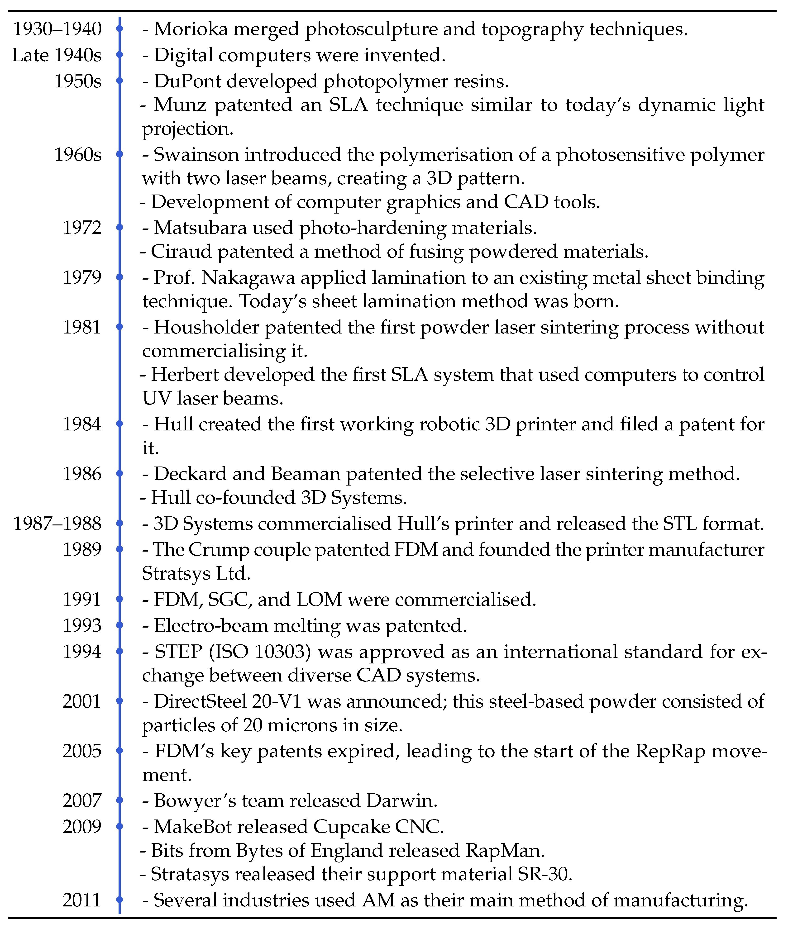
1.1. A Brief History of AM
1.1.1. Before 1980—The Beginning
1.1.2. The 1980s—The Rise of Modern 3D Printers
1.1.3. The 1990s and 2000s—A Period of Growth
1.1.4. From 2010 to the Present
- AM can create topologically optimised structures, which are difficult to manufacture with traditional casting or forging processes;
- AM can be used to generate novel characteristics in materials, such as dislocation networks;
- AM greatly improves the material utilisation rate.
2. 3D Printing Process, Methods, and Optimisation
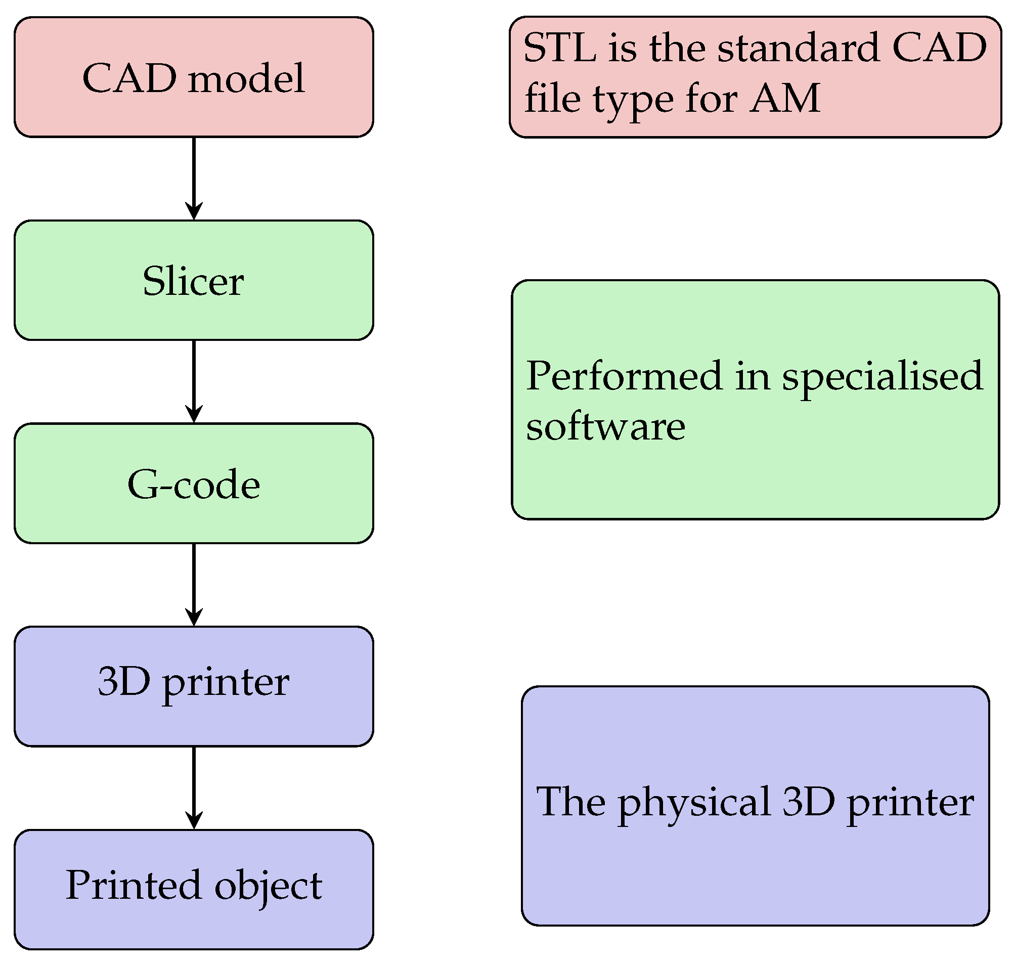
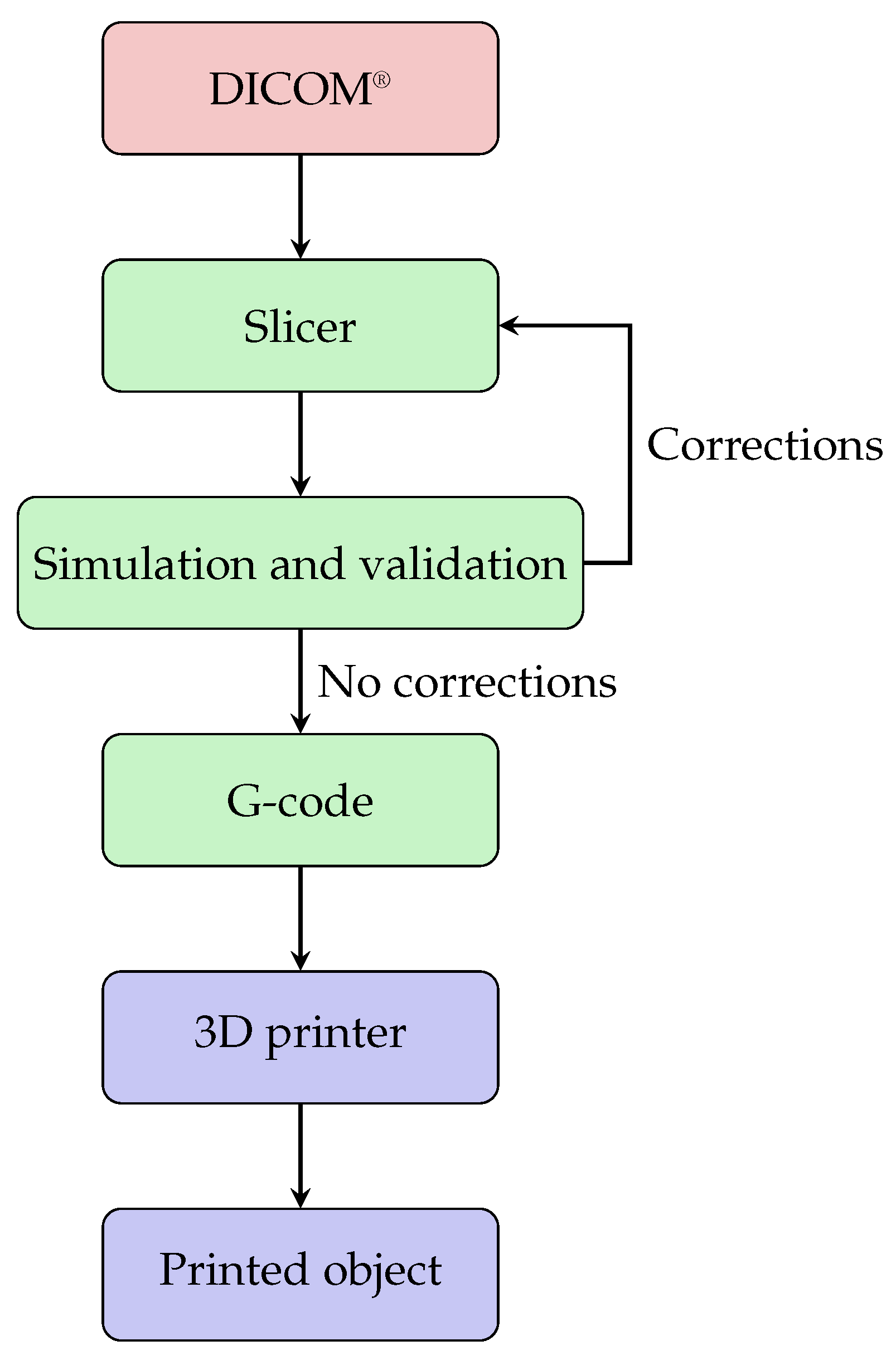
2.1. From CAD to G-Code
2.2. AM Methods
2.3. Optimisation
3. Trending Optimisation Topics
3.1. The Usage of AI in AM Today
3.2. STL
3.3. Slicer
3.4. Simulation
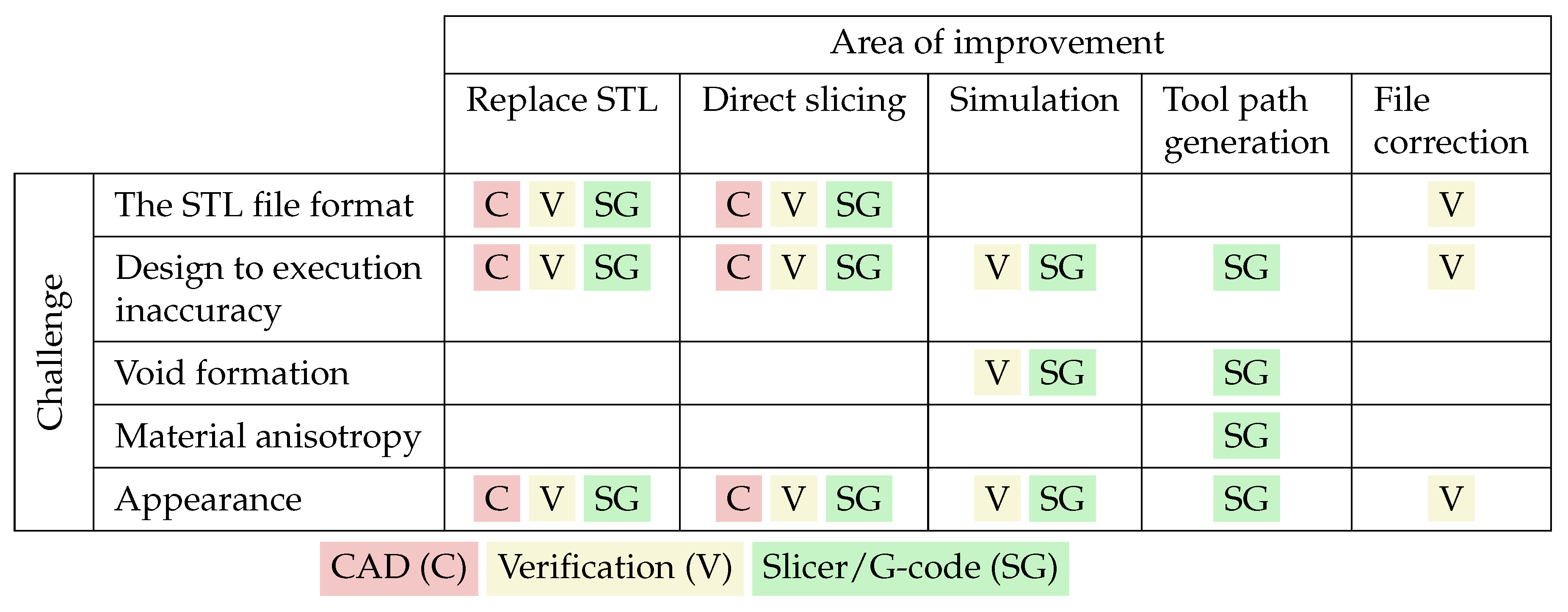
4. Challenges
4.1. The STL File Format
4.2. Design to Execution Inaccuracy
4.3. Void Formation
4.4. Material Anisotropy
4.5. Appearance
5. Future Perspectives
5.1. STL
5.2. Simulation
5.3. Customisation
5.4. The Future Usage of AI in AM
6. The Potential for Optimisation
7. Conclusions
Author Contributions
Funding
Conflicts of Interest
References
- Ugur, M. Dilberoglu, Bahar Gharehpapagh, Ulas Yaman, and Melik Dolen. The role of additive manufacturing in the era of industry 4.0. Procedia Manuf. 2017, 11, 545–554. [Google Scholar]
- Ngo, T.D.; Kashani, A.; Imbalzano, G.; Nguyen, K.T.Q.; Hui, D. Additive manufacturing (3d printing): A review of materials, methods, applications and challenges. Compos. Part B Eng. 2018, 143, 172–196. [Google Scholar] [CrossRef]
- Hong, Q.; Lin, L.; Li, Q.; Jiang, Z.; Fang, J.; Wang, B.; Liu, K.; Wu, Q.; Huang, C. A direct slicing technique for the 3d printing of implicitly represented medical models. Comput. Biol. Med. 2021, 135, 104534. [Google Scholar] [CrossRef]
- Kouraytem, N.; Li, X.; Tan, W.; Kappes, B.; Spear, A.D. Modeling process–structure–property relationships in metal additive manufacturing: A review on physics-driven versus data-driven approaches. J. Phys. Mater. 2021, 4, 032002. [Google Scholar] [CrossRef]
- Singh, S.; Mehla, S.; Bhargava, S.K.; Ramakrishna, S. History and Evolution of Additive Manufacturing; Springer Nature: Singapore, 2022; pp. 19–51. [Google Scholar]
- Thompson, M.K.; Moroni, G.; Vaneker, T.; Fadel, G.; Campbell, R.I.; Gibson, I.; Bernard, A.; Schulz, J.; Graf, P.; Ahuja, B.; et al. Design for additive manufacturing: Trends, opportunities, considerations, and constraints. CIRP Ann. 2016, 65, 737–760. [Google Scholar] [CrossRef]
- Zhai, Y.; Lados, D.A.; LaGoy, J.L. Additive manufacturing: Making imagination the major limitation. JOM 2014, 66, 808–816. [Google Scholar] [CrossRef]
- Balletti, C.; Ballarin, M.; Guerra, F. 3d printing: State of the art and future perspectives. J. Cult. Herit. 2017, 26, 172–182. [Google Scholar] [CrossRef]
- Horvath, J. A Brief History of 3D Printing; Apress: Berkeley, CA, USA, 2014; pp. 3–10. [Google Scholar]
- Wohlers, T.; Gornet, T. History of Additive Manufacturing. Available online: https://papers.ssrn.com/sol3/papers.cfm?abstract_id=4474824 (accessed on 29 March 2024).
- Bonnard, R. An advanced step-nc platform for additive manufacturing. In Industrializing Additive Manufacturing—Proceedings of Additive Manufacturing in Products and Applications—AMPA2017; Meboldt, M., Klahn, C., Eds.; Springer International Publishing: Cham, Switzerland, 2018; pp. 127–136. [Google Scholar]
- Xu, X.W.; Wang, L.; Rong, Y. Step-nc and function blocks for interoperable manufacturing. IEEE Trans. Autom. Sci. Eng. 2006, 3, 297–308. [Google Scholar] [CrossRef][Green Version]
- Benthall, L.; Briggs, T.; Downie, B.; Gischner, B.; Kassel, B.; Wood, R. STEP for Shipbuilding: A Solution for Product Model Data Exchange. J. Ship Prod. 2003, 19, 44–52. [Google Scholar] [CrossRef]
- Sandeep, B.; Kannan, T.T.M.; Chandradass, J.; Ganesan, M.; Rajan, A.J. Scope of 3d printing in manufacturing industries—A review. Mater. Today Proc. 2021, 45, 6941–6945. [Google Scholar] [CrossRef]
- Vafadar, A.; Guzzomi, F.; Rassau, A.; Hayward, K. Advances in metal additive manufacturing: A review of common processes, industrial applications, and current challenges. Appl. Sci. 2021, 11, 1213. [Google Scholar] [CrossRef]
- Tom, T.; Sreenilayam, S.P.; Brabazon, D.; Jose, J.P.; Joseph, B.; Madanan, K.; Thomas, S. Additive manufacturing in the biomedical field-recent research developments. Results Eng. 2022, 16, 100661. [Google Scholar] [CrossRef]
- Zocca, A.; Wilbig, J.; Waske, A.; Günster, J.; Widjaja, M.P.; Neumann, C.; Clozel, M.; Meyer, A.; Ding, J.; Zhou, Z.; et al. Challenges in the technology development for additive manufacturing in space. Chin. J. Mech. Eng. Addit. Manuf. Front. 2022, 1, 100018. [Google Scholar] [CrossRef]
- Careri, F.; Khan, R.H.U.; Todd, C.; Attallah, M.M. Additive manufacturing of heat exchangers in aerospace applications: A review. Appl. Therm. Eng. 2023, 235, 121387. [Google Scholar] [CrossRef]
- Madhavadas, V.; Srivastava, D.; Chadha, U.; Raj, S.A.; Sultan, M.T.H.; Shahar, F.S.; Shah, A.U.M. A review on metal additive manufacturing for intricately shaped aerospace components. CIRP J. Manuf. Sci. Technol. 2022, 39, 18–36. [Google Scholar] [CrossRef]
- Goodacre, B.J.; Goodacre, C.J. Additive manufacturing for complete denture fabrication: A narrative review. J. Prosthodont. 2022, 31, 47–51. [Google Scholar] [CrossRef] [PubMed]
- Medvedev, A.E.; Maconachie, T.; Leary, M.; Qian, M.; Brandt, M. Perspectives on additive manufacturing for dynamic impact applications. Mater. Des. 2022, 221, 110963. [Google Scholar] [CrossRef]
- Selema, A.; Ibrahim, M.N.; Sergeant, P. Metal additive manufacturing for electrical machines: Technology review and latest advancements. Energies 2022, 15, 1076. [Google Scholar] [CrossRef]
- Rouf, S.; Raina, A.; Haq, M.I.U.; Naveed, N.; Jeganmohan, S.; Kichloo, A.F. 3d printed parts and mechanical properties: Influencing parameters, sustainability aspects, global market scenario, challenges and applications. Adv. Ind. Eng. Polym. Res. 2022, 5, 143–158. [Google Scholar] [CrossRef]
- Xiong, Y.; Lu, H.; Li, G.; Xia, S.; Wang, Z.; Xu, Y. Game changer or threat: The impact of 3d printing on the logistics supplier circular supply chain. Ind. Mark. Manag. 2022, 106, 461–475. [Google Scholar] [CrossRef]
- Qi, X.; Chen, G.; Li, Y.; Cheng, X.; Li, C. Applying neural-network-based machine learning to additive manufacturing: Current applications, challenges, and future perspectives. Engineering 2019, 5, 721–729. [Google Scholar] [CrossRef]
- Bonnard, R.; Hascoët, J.Y.; Mognol, P. Data model for additive manufacturing digital thread: State of the art and perspectives. Int. J. Comput. Integr. Manuf. 2019, 32, 1170–1191. [Google Scholar] [CrossRef]
- Pei, E.; Ressin, M.; Campbell, R.I.; Eynard, B.; Xiao, J. Investigating the impact of additive manufacturing data exchange standards for re-distributed manufacturing. Prog. Addit. Manuf. 2019, 4, 331–344. [Google Scholar] [CrossRef]
- Nieto, D.M.; Sánchez, D.M. Design for additive manufacturing: Tool review and a case study. Appl. Sci. 2021, 11, 1571. [Google Scholar] [CrossRef]
- Lee, J.; An, J.; Chua, C.K. Fundamentals and applications of 3d printing for novel materials. Appl. Mater. Today 2017, 7, 120–133. [Google Scholar] [CrossRef]
- Singh, T.; Kumar, S.; Sehgal, S. 3d printing of engineering materials: A state of the art review. Mater. Today Proc. 2020, 28, 1927–1931. [Google Scholar] [CrossRef]
- Schwaar, C. The 7 Main Types of 3d Printing Technology. Available online: https://all3dp.com/1/types-of-3d-printers-3d-printing-technology/ (accessed on 29 March 2024).
- Ziaee, M.; Crane, N.B. Binder jetting: A review of process, materials, and methods. Addit. Manuf. 2019, 28, 781–801. [Google Scholar] [CrossRef]
- Park, S.-I.; Rosen, D.W.; Choi, S.k.; Duty, C.E. Effective mechanical properties of lattice material fabricated by material extrusion additive manufacturing. Addit. Manuf. 2014, 1, 12–23. [Google Scholar]
- Gibson, I.; Rosen, D.; Stucker, B. Directed Energy Deposition Processes; Springer: New York, NY, USA, 2015; pp. 245–268. [Google Scholar]
- Gülcan, O.; Günaydın, K.; Tamer, A. The state of the art of material jetting—A critical review. Polymers 2021, 13, 2829. [Google Scholar] [CrossRef]
- Gibson, I.; Rosen, D.; Stucker, B.; Khorasani, M. Powder Bed Fusion; Springer International Publishing: Cham, Switzerland, 2021; pp. 125–170. [Google Scholar]
- Kong, C.Y.; Soar, R.C.; Dickens, P.M. Optimum process parameters for ultrasonic consolidation of 3003 aluminium. J. Mater. Process. Technol. 2004, 146, 181–187. [Google Scholar] [CrossRef]
- Gibson, I.; Rosen, D.; Stucker, B.; Khorasani, M. Sheet Lamination; Springer International Publishing: Cham, Switzerland, 2021; pp. 253–283. [Google Scholar]
- Al Rashid, A.; Ahmed, W.; Khalid, M.Y.; Koç, M. Vat photopolymerization of polymers and polymer composites: Processes and applications. Addit. Manuf. 2021, 47, 102279. [Google Scholar] [CrossRef]
- Bong, S.H.; Nematollahi, B.; Nazari, A.; Xia, M.; Sanjayan, J. Method of optimisation for ambient temperature cured sustainable geopolymers for 3d printing construction applications. Materials 2019, 12, 902. [Google Scholar] [CrossRef] [PubMed]
- Tan, D.K.; Maniruzzaman, M.; Nokhodchi, A. Development and optimisation of novel polymeric compositions for sustained release theophylline caplets (printcap) via fdm 3d printing. Polymers 2020, 12, 27. [Google Scholar] [CrossRef] [PubMed]
- Zhao, P.; He, Y.; Trindade, G.F.; Baumers, M.; Irvine, D.J.; Hague, R.J.M.; Ashcroft, I.A.; Wildman, R.D. Modelling the influence of uv curing strategies for optimisation of inkjet based 3d printing. Mater. Des. 2021, 208, 109889. [Google Scholar] [CrossRef]
- Heiden, B.; Alieksieiev, V.; Volk, M.; Tonino-Heiden, B. Framing artificial intelligence (ai) additive manufacturing (am). Procedia Comput. Sci. 2021, 186, 387–394. [Google Scholar] [CrossRef]
- Nguyen, P.D.; Nguyen, T.Q.; Tao, Q.B.; Vogel, F.; Nguyen-Xuan, H. A data-driven machine learning approach for the 3d printing process optimisation. Virtual Phys. Prototyp. 2022, 17, 768–786. [Google Scholar] [CrossRef]
- Tan, C.; Weng, F.; Sui, S.; Chew, Y.; Bi, G. Progress and perspectives in laser additive manufacturing of key aeroengine materials. Int. J. Mach. Tools Manuf. 2021, 170, 103804. [Google Scholar] [CrossRef]
- Khorasani, M.; Ghasemi, A.; Rolfe, B.; Gibson, I. Additive manufacturing a powerful tool for the aerospace industry. Rapid Prototyp. J. 2022, 28, 87–100. [Google Scholar] [CrossRef]
- Ghomi, E.R.; Khosravi, F.; Neisiany, R.E.; Singh, S.; Ramakrishna, S. Future of additive manufacturing in healthcare. Curr. Opin. Biomed. Eng. 2021, 17, 100255. [Google Scholar]
- Ramola, M.; Yadav, V.; Jain, R. On the adoption of additive manufacturing in healthcare: A literature review. J. Manuf. Technol. Manag. 2019, 30, 48–69. [Google Scholar] [CrossRef]
- Castro, B.M.; Elbadawi, M.; Ong, J.J.; Pollard, T.; Song, Z.; Gaisford, S.; Pérez, G.; Basit, A.W.; Cabalar, P.; Goyanes, A. Machine learning predicts 3d printing performance of over 900 drug delivery systems. J. Control. Release 2021, 337, 530–545. [Google Scholar] [CrossRef]
- Yadav, D.; Chhabra, D.; Garg, R.K.; Ahlawat, A.; Phogat, A. Optimization of fdm 3d printing process parameters for multi-material using artificial neural network. Mater. Today Proc. 2020, 21, 1583–1591. [Google Scholar] [CrossRef]
- Sarabi, M.R.; Alseed, M.M.; Karagoz, A.A.; Tasoglu, S. Machine learning-enabled prediction of 3d-printed microneedle features. Biosensors 2022, 12, 491. [Google Scholar] [CrossRef]
- Zhu, H.S.P.Z.; Ng, D.W.H.; McAlpine, M.C. 3d-printed multifunctional materials enabled by artificial-intelligence-assisted fabrication technologies. Nat. Rev. Mater. 2021, 6, 27–47. [Google Scholar] [CrossRef]
- Elbadawi, M.; McCoubrey, L.E.; Gavins, F.K.H.; Ong, J.J.; Goyanes, A.; Gaisford, S.; Basit, A.W. Harnessing artificial intelligence for the next generation of 3d printed medicines. Adv. Drug Deliv. Rev. 2021, 175, 113805. [Google Scholar] [CrossRef]
- Wang, C.; Tan, X.P.; Tor, S.B.; Lim, C.S. Machine learning in additive manufacturing: State-of-the-art and perspectives. Addit. Manuf. 2020, 36, 101538. [Google Scholar] [CrossRef]
- Meng, L.; McWilliams, B.; Jarosinski, W.; Park, H.-Y.; Jung, Y.-G.; Lee, J.; Zhang, J. Machine learning in additive manufacturing: A review. JOM 2020, 72, 2363–2377. [Google Scholar] [CrossRef]
- Goldberg, Y. Neural network methods for natural language processing. Synth. Lect. Hum. Lang. Technol. 2017, 10, 1–309. [Google Scholar]
- Abiodun, O.I.; Jantan, A.; Omolara, A.E.; Dada, K.V.; Mohamed, N.A.; Arshad, H. State-of-the-art in artificial neural network applications: A survey. Heliyon 2018, 4, e00938. [Google Scholar] [CrossRef]
- Hiller, J.D.; Lipson, H. Stl 2.0: A proposal for a universal multi-material additive manufacturing file format. In Proceedings of the 2009 International Solid Freeform Fabrication Symposium, Austin, TX, USA, 3–5 August 2009; University of Texas at Austin: Austin, TX, USA, 2009. [Google Scholar]
- van Eijnatten, M.; van Dijk, R.; Dobbe, J.; Streekstra, G.; Koivisto, J.; Wolff, J. Ct image segmentation methods for bone used in medical additive manufacturing. Med Eng. Phys. 2018, 51, 6–16. [Google Scholar] [CrossRef]
- Huotilainen, E.; Jaanimets, R.; Valášek, J.; Marcián, P.; Salmi, M.; Tuomi, J.; Mäkitie, A.; Wolff, J. Inaccuracies in additive manufactured medical skull models caused by the dicom to stl conversion process. J. Cranio-Maxillofac. Surg. 2014, 42, e259–e265. [Google Scholar] [CrossRef] [PubMed]
- Stoor, P.; Suomalainen, A.; Lindqvist, C.; Mesimäki, K.; Danielsson, D.; Westermark, A.; Kontio, R.K. Rapid prototyped patient specific implants for reconstruction of orbital wall defects. J. Cranio-Maxillofac. Surg. 2014, 42, 1644–1649. [Google Scholar] [CrossRef] [PubMed]
- D’Addazio, G.; Xhajanka, E.; Traini, T.; Santilli, M.; Rexhepi, I.; Murmura, G.; Caputi, S.; Sinjari, B. Accuracy of dicom–dicom vs. dicom–stl protocols in computer-guided surgery: A human clinical study. J. Clin. Med. 2022, 11, 2336. [Google Scholar] [CrossRef] [PubMed]
- Osti, F.; Santi, G.; Neri, M.; Liverani, A.; Frizziero, L.; Stilli, S.; Maredi, E.; Zarantonello, P.; Gallone, G.; Stallone, S.; et al. Ct conversion workflow for intraoperative usage of bony models: From dicom data to 3d printed models. Appl. Sci. 2019, 9, 708. [Google Scholar] [CrossRef]
- Allaire, G.; Bogosel, B. Optimizing supports for additive manufacturing. Struct. Multidiscip. Optim. 2018, 58, 2493–2515. [Google Scholar] [CrossRef]
- King, B.; Rennie, A.; Bennett, G. An efficient triangle mesh slicing algorithm for all topologies in additive manufacturing. Int. J. Adv. Manuf. Technol. 2021, 112, 1023–1033. [Google Scholar] [CrossRef]
- Yigit, I.E.; Lazoglu, I. Helical slicing method for material extrusion-based robotic additive manufacturing. Prog. Addit. Manuf. 2019, 4, 225–232. [Google Scholar] [CrossRef]
- Adams, D.; Turner, C.J. An implicit slicing method for additive manufacturing processes. Virtual Phys. Prototyp. 2018, 13, 2–7. [Google Scholar] [CrossRef]
- Alkadi, F.; Lee, K.; Bashiri, A.H.; Choi, J. Conformal additive manufacturing using a direct-print process. Addit. Manuf. 2020, 32, 100975. [Google Scholar] [CrossRef]
- Tan, W.S.; Juhari, M.A.B.; Shi, Q.; Chen, S.; Campolo, D.; Song, J. Development of a new additive manufacturing platform for direct freeform 3d printing of intrinsically curved flexible membranes. Addit. Manuf. 2020, 36, 101563. [Google Scholar] [CrossRef]
- Gupta, P.; Krishnamoorthy, B.; Dreifus, G. Continuous toolpath planning in a graphical framework for sparse infill additive manufacturing. Comput.-Aided Des. 2020, 127, 102880. [Google Scholar] [CrossRef]
- Xia, L.; Lin, S.; Ma, G. Stress-based tool-path planning methodology for fused filament fabrication. Addit. Manuf. 2020, 32, 101020. [Google Scholar] [CrossRef]
- Chacón, J.M.; Sanchez-Reyes, J.; Vallejo, J.; Núñez, P.J. G-code generation in a nurbs workflow for precise additive manufacturing. Rapid Prototyp. J. 2022, 28, 65–76. [Google Scholar] [CrossRef]
- Frazier, W.E. Metal additive manufacturing: A review. J. Mater. Eng. Perform. 2014, 23, 1917–1928. [Google Scholar] [CrossRef]
- Arrizubieta, J.I.; Ukar, O.; Ostolaza, M.; Mugica, A. Study of the environmental implications of using metal powder in additive manufacturing and its handling. Metals 2020, 10, 261. [Google Scholar] [CrossRef]
- Gisario, A.; Kazarian, M.; Martina, F.; Mehrpouya, M. Metal additive manufacturing in the commercial aviation industry: A review. J. Manuf. Syst. 2019, 53, 124–149. [Google Scholar] [CrossRef]
- Cook, P.S.; Murphy, A.B. Simulation of melt pool behaviour during additive manufacturing: Underlying physics and progress. Addit. Manuf. 2020, 31, 100909. [Google Scholar] [CrossRef]
- Körner, C.; Markl, M.; Koepf, J.A. Modeling and simulation of microstructure evolution for additive manufacturing of metals: A critical review. Metall. Mater. Trans. A 2020, 51, 4970–4983. [Google Scholar] [CrossRef]
- Song, X.; Feih, S.; Zhai, W.; Sun, C.; Li, F.; Maiti, R.; Wei, J.; Yang, Y.; Oancea, V.; Brandt, L.R.; et al. Advances in additive manufacturing process simulation: Residual stresses and distortion predictions in complex metallic components. Mater. Des. 2020, 193, 108779. [Google Scholar] [CrossRef]
- Comminal, R.; Serdeczny, M.P.; Pedersen, D.B.; Spangenberg, J. Motion planning and numerical simulation of material deposition at corners in extrusion additive manufacturing. Addit. Manuf. 2019, 29, 100753. [Google Scholar] [CrossRef]
- Abdulhameed, O.; Al-Ahmari, A.; Ameen, W.; Mian, S.H. Additive manufacturing: Challenges, trends, and applications. Adv. Mech. Eng. 2019, 11, 1687814018822880. [Google Scholar] [CrossRef]
- Bhuvanesh Kumar, M.; Sathiya, P. Methods and materials for additive manufacturing: A critical review on advancements and challenges. Thin-Walled Struct. 2021, 159, 107228. [Google Scholar] [CrossRef]
- Oropallo, W.; Piegl, L.A. Ten challenges in 3d printing: Engineering with computers. Compos. Part B Eng. 2016, 32, 135–148. [Google Scholar]
- Xiao, J.; Anwer, N.; Durupt, A.; Duigou, J.L.; Eynard, B. Information exchange standards for design, tolerancing and additive manufacturing: A research review. Int. J. Interact. Des. Manuf. 2018, 12, 495–504. [Google Scholar] [CrossRef]
- Krueckemeier, S.; Anderl, R.; Schleich, B. File format selection for efficient digital process chains in additive manufacturing. Proc. Des. Soc. 2023, 3, 1875–1884. [Google Scholar] [CrossRef]
- Godec, D.; Gonzalez-Gutierrez, J.; Nordin, A.; Pei, E.; Ureña, J. A Guide to Additive Manufacturing; Springer Nature: Cham, Switzerland, 2022. [Google Scholar]
- Zhao, D.; Guo, W. Shape and performance controlled advanced design for additive manufacturing: A review of slicing and path planning. J. Manuf. Sci. Eng. 2020, 142, 010801. [Google Scholar] [CrossRef]
- Schaechtl, P.; Schleich, B.; Wartzack, S. On the potential of slicing algorithms in additive manufacturing for the optimization of geometrical part accuracy. Procedia CIRP 2022, 114, 215–220. [Google Scholar] [CrossRef]
- Brion, D.A.J.; Pattinson, S.W. Generalisable 3d printing error detection and correction via multi-head neural networks. Nat. Commun. 2022, 13, 4654. [Google Scholar] [CrossRef] [PubMed]
- Wylie, B.; Moore, C. Optical methods of error detection in additive manufacturing: A literature review. J. Manuf. Mater. Process. 2023, 7, 80. [Google Scholar] [CrossRef]
- Gibson, I.; Rosen, D.; Strucker, B. Post-Processing, 2nd ed.; Springer: New York, NY, USA, 2010. [Google Scholar]
- Lekas, S.; Drummond, R.; Grant, P.; Duncan, S.R. Control of additive manufacturing for radio-frequency devices with spatially varying dielectric properties. IEEE Trans. Control. Syst. Technol. 2024. [Google Scholar] [CrossRef]
- Sun, X.; Mazur, M.; Cheng, C. A review of void reduction strategies in material extrusion-based additive manufacturing. Addit. Manuf. 2023, 67, 103463. [Google Scholar] [CrossRef]
- Paul, S.C.; Tay, Y.W.D.; Panda, B.; Tan, M.J. Fresh and hardened properties of 3d printable cementitious materials for building and construction. Arch. Civ. Mech. Eng. 2018, 18, 311–319. [Google Scholar] [CrossRef]
- Papon, E.A.; Haque, A.; Sharif, M. Numerical study for the improvement of bead spreading architecture with modified nozzle geometries in additive manufacturing of polymers. Rapid Prototyp. J. 2021, 27, 518–529. [Google Scholar] [CrossRef]
- Qiu, D.; Langrana, N. Void eliminating toolpath for extrusion-based multi-material layered manufacturing. Rapid Prototyp. J. 2002, 8, 38–45. [Google Scholar] [CrossRef]
- Kuipers, T.; Doubrovski, E.L.; Wu, J.; Wang, C.C.L. A framework for adaptive width control of dense contour-parallel toolpaths in fused deposition modeling. Comput.-Aided Des. 2020, 128, 102907. [Google Scholar] [CrossRef]
- Lin, S.; Xia, L.; Ma, G.; Zhou, S.; Xie, Y.M. A maze-like path generation scheme for fused deposition modeling. Int. J. Adv. Manuf. Technol. 2019, 104, 1509–1519. [Google Scholar] [CrossRef]
- Levenhagen, N.P.; Dadmun, M.D. Interlayer diffusion of surface segregating additives to improve the isotropy of fused deposition modeling products. Polymer 2018, 152, 35–41. [Google Scholar] [CrossRef]
- Wang, L.; Gramlich, W.; Gardner, D. Improving the impact strength of poly(lactic acid) (pla) in fused layer modeling (flm). Polymer 2017, 114, 242–248. [Google Scholar] [CrossRef]
- Aliheidari, N.; Christ, J.; Tripuraneni, R.; Nadimpalli, S.; Ameli, A. Interlayer adhesion and fracture resistance of polymers printed through melt extrusion additive manufacturing process. Mater. Des. 2018, 156, 351–361. [Google Scholar] [CrossRef]
- Ravi, A.; Deshpande, A.; Hsu, K.H. An in-process laser localized pre-deposition heating approach to inter-layer bond strengthening in extrusion based polymer additive manufacturing. J. Manuf. Process. 2016, 24, 179–185. [Google Scholar] [CrossRef]
- Yadollahi, A.; Shamsaei, N. Additive manufacturing of fatigue resistant materials: Challenges and opportunities. Int. J. Fatigue 2017, 98, 14–31. [Google Scholar] [CrossRef]
- Torres, J.; Cotelo, J.; Karl, J.; Gordon, A.P. Mechanical property optimization of fdm pla in shear with multiple objectives. JOM 2015, 67, 1183–1193. [Google Scholar] [CrossRef]
- Li, G.; Zhao, J.; Jiang, J.; Jiang, H.; Wu, W.; Tang, M. Ultrasonic strengthening improves tensile mechanical performance of fused deposition modeling 3d printing. Int. J. Adv. Manuf. Technol. 2018, 96, 2747–2755. [Google Scholar] [CrossRef]
- Zhang, P.; Liu, J.; To, A.C. Role of anisotropic properties on topology optimization of additive manufactured load bearing structures. Scr. Mater. 2017, 135, 148–152. [Google Scholar] [CrossRef]
- Zohdi, N.; Yang, R. Material anisotropy in additively manufactured polymers and polymer composites: A review. Polymers 2021, 13, 3368. [Google Scholar] [CrossRef]
- Shaffer, S.; Yang, K.; Vargas, J.; Di Prima, M.A.; Voit, W. On reducing anisotropy in 3d printed polymers via ionizing radiation. Polymer 2014, 55, 5969–5979. [Google Scholar] [CrossRef]
- Cooke, W.; Tomlinson, R.; Burguete, R.; Johns, D.; Vanard, G. Anisotropy, homogeneity and ageing in an sls polymer. Rapid Prototyp. J. 2011, 17, 269–279. [Google Scholar] [CrossRef]
- Guessasma, S.; Belhabib, S.; Nouri, H.; Ben Hassana, O. Anisotropic damage inferred to 3d printed polymers using fused deposition modelling and subject to severe compression. Eur. Polym. J. 2016, 85, 324–340. [Google Scholar] [CrossRef]
- Muhler, T.; Gomes, C.M.; Heinrich, J.; Günster, J. Slurry-based additive manufacturing of ceramics. Int. J. Appl. Ceram. Technol. 2015, 12, 18–25. [Google Scholar] [CrossRef]
- Manière, C.; Kerbart, G.; Harnois, C.; Marinel, S. Modeling sintering anisotropy in ceramic stereolithography of silica. Acta Mater. 2020, 182, 163–171. [Google Scholar] [CrossRef]
- Wu, X.; Xu, C.; Zhang, Z.; Guo, C. Modeling and visualization of layered curing conversion profile in ceramic mask projection stereolithography process. Ceram. Int. 2020, 46, 25750–25757. [Google Scholar] [CrossRef]
- Carroll, B.E.; Palmer, T.A.; Beese, A.M. Anisotropic tensile behavior of Ti–6Al–4V components fabricated with directed energy deposition additive manufacturing. Acta Mater. 2015, 87, 309–320. [Google Scholar] [CrossRef]
- Zhu, Y.; Tian, X.; Li, J.; Wang, H. The anisotropy of laser melting deposition additive manufacturing Ti–6.5Al–3.5Mo–1.5Zr–0.3Si titanium alloy. Mater. Des. 2015, 67, 538–542. [Google Scholar] [CrossRef]
- Körner, C.; Helmer, H.; Bauereiß, A.; Singer, R. Tailoring the grain structure of IN718 during selective electron beam melting. MATEC Web Conf. 2014, 14, 08001. [Google Scholar] [CrossRef]
- Prajapati, M.J.; Kumar, A.; Lin, S.; Jeng, J. Reducing mechanical anisotropy in material extrusion process using bioinspired architectured lattice structures. Addit. Manuf. 2023, 66, 103480. [Google Scholar] [CrossRef]
- Li, H.; Liu, Y.; Colombo, P.; Li, W.; Liu, Y.; Hu, K.; Lu, Z. The influence of sintering procedure and porosity on the properties of 3d printed alumina ceramic cores. Ceram. Int. 2021, 47, 27668–27676. [Google Scholar] [CrossRef]
- Li, Q.; Hou, W.; Liang, J.; Zhang, C.; Li, J.; Zhou, Y.; Sun, X. Controlling the anisotropy behaviour of 3d printed ceramic cores: From intralayer particle distribution to interlayer pore evolution. Addit. Manuf. 2022, 58, 103055. [Google Scholar] [CrossRef]
- Tan, Q.; Zhang, J.; Mo, N.; Fan, Z.; Yin, Y.; Bermingham, M.; Liu, Y.; Huang, H.; Zhang, M. A novel method to 3d-print fine-grained alsi10mg alloy with isotropic properties via inoculation with lab6 nanoparticles. Addit. Manuf. 2020, 32, 101034. [Google Scholar] [CrossRef]
- Chen, S.; Tan, Q.; Gao, W.; Wu, G.; Fan, J.; Feng, Z.; Huang, T.; Godfrey, A.W.; Zhang, M.; Huang, X. Effect of heat treatment on the anisotropy in mechanical properties of selective laser melted alsi10mg. Mater. Sci. Eng. A 2022, 858, 144130. [Google Scholar] [CrossRef]
- Hossain, U.; Ghouse, S.; Nai, K.; Jeffers, J.R.T. Controlling and testing anisotropy in additively manufactured stochastic structures. Addit. Manuf. 2021, 39, 101849. [Google Scholar] [CrossRef]
- Ahn, D.; Kim, H.; Lee, S. Fabrication direction optimization to minimize post-machining in layered manufacturing. Int. J. Mach. Tools Manuf. 2007, 47, 593–606. [Google Scholar] [CrossRef]
- Das, P.; Chandran, R.; Samant, R.; Anand, S. Optimum part build orientation in additive manufacturing for minimizing part errors and support structures. Procedia Manuf. 2015, 1, 343–354. [Google Scholar] [CrossRef]
- Mahamood, R.M.; Akinlabi, E.T.; Shukla, M.; Pityana, S. Revolutionary Additive Manufacturing: An Overview; University of Johannesburg Institutional Repository (UJIR): Johannesburg, South Africa, 2014. [Google Scholar]


| Printing Method | Description of Process |
|---|---|
| Binder jetting (BJ) | Deposits liquid binder onto a thin layer of powder particles, gluing the powder material to an object [32]. |
| Material extrusion (ME) | Loads and liquefies the material, moving it through a nozzle to deposit a thin filament [33]. |
| Direct energy deposition (DED) | Melts the material as it is being deposited from the nozzle. The deposited material can comprise wires or powder [34]. |
| Material jetting (MJ) | Air-excluding tanks store the photopolymer material. The material is heated in a transition line and deposited as droplets, forming a very thin layer on the building area [35]. |
| Powder bed fusion (PBF) | Uses one or more thermal source for fusion between powder particles; then, a new layer of powder material is applied. This process is repeated until the finished object has been created [36]. |
| Sheet lamination (SL) | Builds the object using layers of metal sheets, essentially welding them together and removing excess material [37,38]. |
| Vat photopolymerisation (VP) | A curing source invokes a polymerisation reaction in the photosensitive material, creating a layered object [39]. |
| Area of Improvement | Potential Improved Aspect |
|---|---|
| Replace STL |
|
| Direct slicing |
|
| Simulations |
|
| Tool path generation |
|
| File correction |
Disclaimer/Publisher’s Note: The statements, opinions and data contained in all publications are solely those of the individual author(s) and contributor(s) and not of MDPI and/or the editor(s). MDPI and/or the editor(s) disclaim responsibility for any injury to people or property resulting from any ideas, methods, instructions or products referred to in the content. |
© 2024 by the authors. Licensee MDPI, Basel, Switzerland. This article is an open access article distributed under the terms and conditions of the Creative Commons Attribution (CC BY) license (https://creativecommons.org/licenses/by/4.0/).
Share and Cite
Henriksen, T.E.; Brustad, T.F.; Dalmo, R.; Pedersen, A. Computer-Aided Optimisation in Additive Manufacturing Processes: A State of the Art Survey. J. Manuf. Mater. Process. 2024, 8, 76. https://doi.org/10.3390/jmmp8020076
Henriksen TE, Brustad TF, Dalmo R, Pedersen A. Computer-Aided Optimisation in Additive Manufacturing Processes: A State of the Art Survey. Journal of Manufacturing and Materials Processing. 2024; 8(2):76. https://doi.org/10.3390/jmmp8020076
Chicago/Turabian StyleHenriksen, Tanja Emilie, Tanita Fossli Brustad, Rune Dalmo, and Aleksander Pedersen. 2024. "Computer-Aided Optimisation in Additive Manufacturing Processes: A State of the Art Survey" Journal of Manufacturing and Materials Processing 8, no. 2: 76. https://doi.org/10.3390/jmmp8020076
APA StyleHenriksen, T. E., Brustad, T. F., Dalmo, R., & Pedersen, A. (2024). Computer-Aided Optimisation in Additive Manufacturing Processes: A State of the Art Survey. Journal of Manufacturing and Materials Processing, 8(2), 76. https://doi.org/10.3390/jmmp8020076