Article

Enhancing the Mechanical Properties of Transient-Liquid-Phase Bonded Inconel 617 to Stainless Steel 310 through Altering Process Parameters and Homogenisation

1
Department of Materials Engineering, Isfahan University of Technology, Isfahan 84156-83111, Iran
2
School of Mechanical Engineering, College of Engineering, University of Tehran, Tehran 14176-14411, Iran
3
Naval Architecture, Ocean and Marine Engineering Department, University of Strathclyde, Glasgow G1 1XQ, UK
*
Authors to whom correspondence should be addressed.
J. Manuf. Mater. Process. 2024, 8(4), 143; https://doi.org/10.3390/jmmp8040143
Submission received: 15 May 2024 / Revised: 24 June 2024 / Accepted: 1 July 2024 / Published: 4 July 2024

Abstract

:
This study investigated the impact of temperature, time, and homogenisation on the transient liquid phase bonding of Inconel 617 to stainless steel 310, employing AWS BNI2 foil as an interlayer. Nine test series were conducted at temperatures of 1050 °C and 1100 °C, with bonding durations ranging from 10 to 60 min. The homogenisation process was carried out on specimens that underwent full isothermal solidification at a temperature of 1170 °C for 180 min. The microscopic analysis indicated that extending the time and raising the bonding temperature resulted in the extension of the isothermal solidified zone, accompanied by a reduction in the quantity of eutectic phases. Complete isothermal solidification was seen exclusively in samples bonded at temperatures of 1050 °C for 60 min and 1100 °C for a duration of 50 min. The size of the diffusion-affected zone expanded as the bonding temperature and duration rose, but the presence of brittle intermetallic phases diminished. The microstructure of the homogenised sample indicated that the diffusion-affected zone had been almost completely eliminated. Hardness variations indicated heightened hardness in the diffusion-affected zone (DAZ) and athermal solidified zone (ASZ). Shear strength is maximised in homogenised specimens with minimised ASZ.

1. Introduction

Inconel 617, a nickel-based superalloy, is widely used in high-temperature applications across various industries due to its exceptional mechanical strength, corrosion resistance, and oxidation resistance [1,2]. However, the high cost of Inconel 617 has led researchers to explore the possibility of joining it with more affordable alloys, such as stainless steel 310. Stainless steel 310 has a compatible chemical composition, mechanical properties, and corrosion resistance, making it a suitable candidate to be joined with Inconel 617. By combining these two alloys, engineers aim to create components that leverage the superior properties of Inconel 617 in critical areas while reducing overall material costs. This approach can potentially expand the use of Inconel 617 in cost-sensitive industries, ultimately leading to improved performance and longevity of critical components in demanding environments. Successfully joining Inconel 617 with stainless steel 310 could revolutionise the design and manufacture of high-temperature components, enabling more cost-effective solutions without compromising performance.
The transient liquid phase (TLP) bonding process is a unique joining technique that combines aspects of both hard brazing and diffusion bonding [3]. In hard brazing, a molten interlayer is used to join components, while diffusion bonding relies heavily on the diffusion phenomenon. TLP bonding, also known as “diffusion brazing”, bridges the gap between these two methods [4,5]. In the TLP process, an interlayer material is sandwiched between the components to be joined, serving as a bonding medium. The entire assembly is then subjected to heat treatment at a temperature slightly above the melting point of the interlayer. This carefully controlled temperature is maintained for a specific duration, allowing the interlayer to melt and the alloying elements from the base metal and the interlayer to undergo interdiffusion. As a result of this diffusion process, the molten interlayer undergoes isothermal solidification, effectively creating a strong, homogeneous bond between the joined components.
The TLP bonding method stands out among other joining techniques due to its unique ability to achieve isothermal solidification. This process is crucial in preventing the inward diffusion of alloying elements into the melt, which, in turn, effectively inhibits the formation of brittle intermetallic phases. By suppressing the growth of these undesirable phases, the TLP method significantly enhances the mechanical properties of the resulting joint [6,7]. This is a key advantage over conventional melting and solidification processes, which typically undergo athermal solidification during continuous cooling. In athermal solidification, the inward diffusion of alloying elements into the solidified front is not restricted, leading to detrimental phases that can compromise the mechanical integrity of the joint. In contrast, the isothermal solidification during TLP bonding ensures that the joint maintains its strength and durability, making it an attractive option for applications requiring high-performance bonded components. Another notable feature of the TLP method is its ability to produce joints with a higher melting temperature than the initial bonding temperature. This phenomenon is attributed to the decrease in the percentage of melting-point-depressant (MPD) elements during the bonding process. MPD elements are responsible for lowering the melting point of the interlayer material, and as they diffuse into the base metal during isothermal solidification, the melting point of the joint increases [8]. This characteristic of TLP bonding is particularly advantageous in applications where the bonded components are exposed to elevated temperatures, as it ensures that the joint maintains its integrity even under harsh operating conditions.
The TLP bonding process results in a joint with three distinct zones, not including the unaffected base metal regions [9]. These zones are the isothermal solidification zone (ISZ), the athermal solidification zone (ASZ), and the diffusion-affected zone (DAZ) in the base metal. The ASZ forms when isothermal solidification is incomplete, leading to the presence of eutectic phases. These phases can be detrimental to the joint’s performance as they lower its melting point and potentially degrade its mechanical and chemical properties [10,11,12]. Careful control of the bonding process is crucial to minimise the formation of the ASZ and ensure optimal joint characteristics. The DAZ, on the other hand, refers to the base metal region influenced by the diffusion of alloying elements from the intermediate layer used in the TLP process. When the intermediate layer contains boron, the DAZ may exhibit the presence of boride compounds, which can impact the local properties of the joint.
The composition of the intermediate layer plays a crucial role in the success of the TLP bonding process. Numerous studies have highlighted the significance of incorporating MPD elements, which effectively lower the melting point of the interlayer material [13]. Among the various options for intermediate layers, those containing boron have garnered significant attention due to the unique properties and benefits that boron offers. boron has proven to be an effective MPD element, significantly reducing the melting point of the interlayer. This reduction in melting point is essential for facilitating the TLP bonding process and ensuring proper diffusion between the interlayer and the base metal. Moreover, boron has been found to prevent the formation of intermetallic compounds, which can be detrimental to the joint’s mechanical properties. The rapid diffusion of boron into the base metal is another advantageous characteristic, as it promotes the homogenisation of the joint. Research has shown that in the absence of a boron-containing intermediate layer, achieving joint homogenisation can be an exceptionally time-consuming process, often requiring up to 2 to 3 days [14]. This prolonged homogenisation time can be impractical and inefficient for many industrial applications. Additionally, the presence of certain MPD elements, such as cadmium, titanium, and aluminium, in some intermediate layers has been linked to the formation of harmful intermetallic compounds. These compounds not only deteriorate the mechanical properties of the joint but also pose significant challenges to its homogenisation. Malekan et al. demonstrated that the uniform distribution of boron along the joint grain boundaries was the primary reason for the improved creep resistance in joints resulting from the TLP process [15]. In light of these findings, carefully selecting the intermediate layer composition, with a particular emphasis on including boron, is paramount for optimising the TLP bonding process. By leveraging the benefits of boron and avoiding the potential drawbacks associated with other MPD elements, researchers and engineers can develop high-quality homogeneous joints with superior mechanical properties.
The bonding temperature in the initial TLP process stage must exceed the intermediate layer’s melting point. Elevating the temperature enhances the diffusion coefficients of various elements, which is crucial for promoting homogenisation and reducing the formation of harmful intermetallic compounds [16]. These intermetallic compounds are detrimental due to their lower diffusion coefficients, which hinder the bonding process. However, it is essential to consider the stability of the base metal structure when selecting the bonding temperature. In some cases, excessively high temperatures can compromise the base metal’s structural integrity, imposing an upper limit on the maximum bonding temperature. Bonding time also plays a crucial role in reducing the athermal solidification of the eutectic zone. A recent study [17] indicated that increasing the bonding time leads to the extension of the isothermal solidification zone. However, phase diagrams and information related to the diffusion of bonding elements serve as invaluable tools for determining the optimal bonding time and temperature. Multiple tests are necessary to establish the ideal bonding parameters for specific alloy combinations. Extensive research has been conducted to investigate the relationships between different alloys and their behaviour during TLP bonding, providing valuable insights for process optimisation.
Mobarakeh et al. conducted a study to investigate the influence of temperature on the microstructure and mechanical properties of Inconel 617 alloy and stainless steel 310 joints formed using the AWS BNi2 interlayer through the TLP bonding process [18]. The findings revealed that although increasing the bonding temperature resulted in a wider isothermal solidification extent, the shear strength of the bonded joints diminished. This phenomenon highlights the importance of carefully selecting the bonding temperature to balance microstructural development and mechanical performance. TLP-bonded joints often exhibit concentration variations across the joint areas, indicating a lack of uniform concentration after bonding. Post-bonding heat treatment can be employed to address this issue and achieve a more homogeneous microstructure. Heat treatment has effectively enhanced the microstructural uniformity and mechanical properties of TLP-bonded joints. In a separate study focusing on the TLP bonding of nickel-based alloy 718 to stainless steel 304, researchers discovered that subjecting the bonded specimens to heat treatment significantly improved their shear strength [19]. This finding underscores the potential benefits of post-bonding heat treatment in optimising the mechanical performance of TLP-bonded joints, particularly in applications involving dissimilar alloys. These studies collectively demonstrate the complex interplay between bonding temperature, microstructural evolution, and mechanical properties in TLP-bonded joints. By carefully controlling the bonding parameters and employing appropriate post-bonding treatments, researchers and engineers can tailor the microstructure and enhance the performance of TLP-bonded joints to meet the specific requirements of various applications.
This study aims to address the need for a comprehensive investigation into the bonding of Inconel 617 alloy with stainless steel 310, which has been underexplored in the existing literature. Understanding the factors that influence the joint properties of these materials is crucial due to their significant potential in high-temperature and corrosive environments. The research focuses on two key aspects: firstly, it examines the impact of temperature and time on the bonded joints’ microstructural development and mechanical performance. Secondly, it explores the effects of homogenisation treatments on these connections’ microstructure and mechanical characteristics. By conducting an in-depth analysis of these factors, this study seeks to provide valuable insights into enhancing the overall performance of Inconel 617–stainless steel 310 joints. Additionally, the successful bonding of these materials has important implications for various industrial applications, such as aerospace, power generation, and chemical processing, where the combination of high-temperature strength and corrosion resistance is essential.

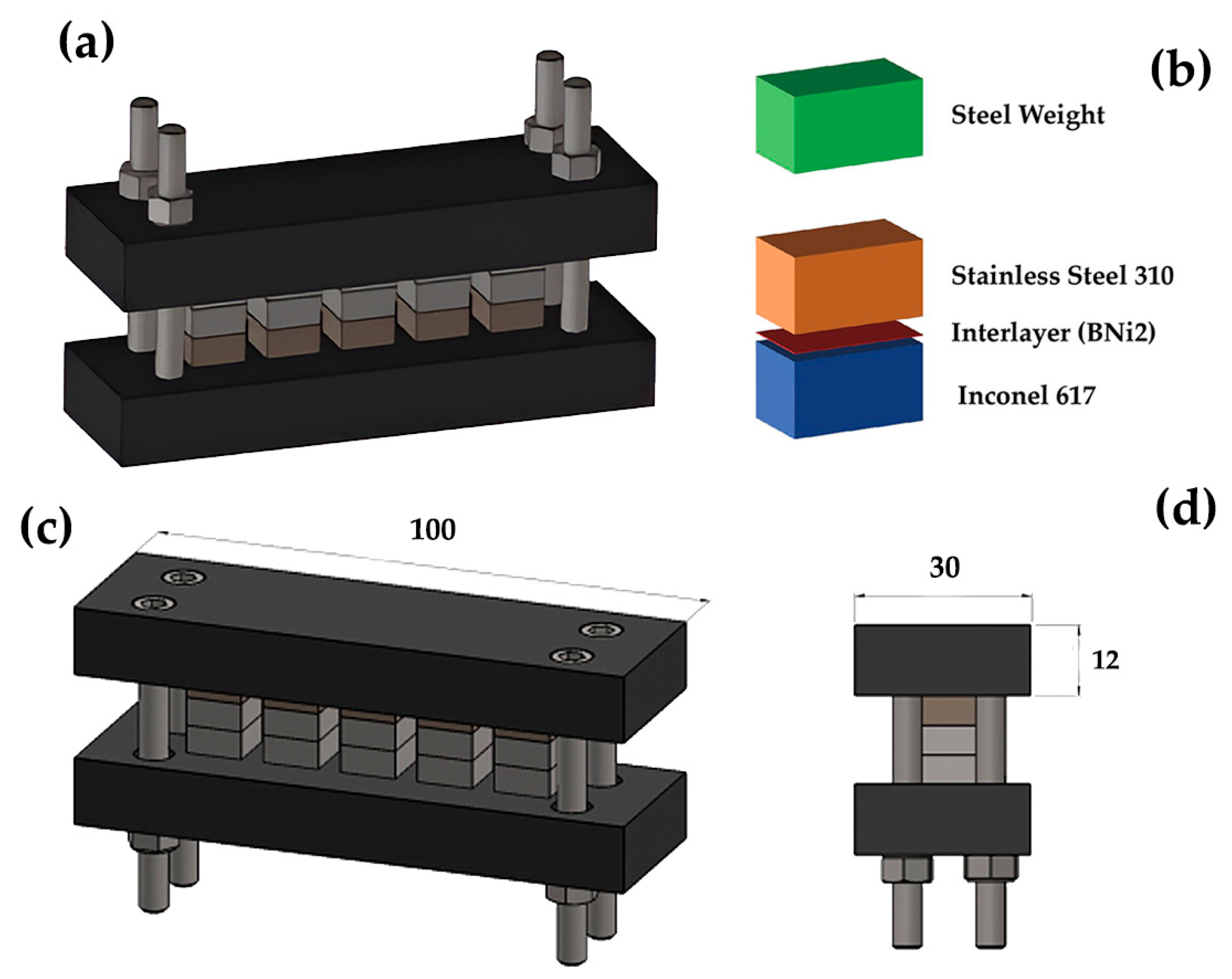
2. Materials and Methods

In this study, the base metals used were Inconel 617 superalloy (Corrotherm Corporation, Hampshire, UK) and austenitic stainless steel 310 (POSCO Corporation, Pohang, Republic of Korea), both in their solution annealing state and in the form of sheets with a thickness of 10 millimetres. The bonding process also involved using an interlayer: an amorphous foil of AWS BNi2 with a thickness of 50 microns (Metglass Corporation, Conway, SC, USA). The specific chemical compositions of the Inconel 617 superalloy, austenitic stainless steel 310, and AWS BNi2 interlayer, as provided by the manufacturers, are presented in Table 1 for reference.
To prepare the base alloys for the bonding process, wire cutting was employed to create specimens with dimensions of 10 × 10 × 5 millimetres. The surfaces of these specimens were then treated using sandpapers with grit sizes ranging from 80 to 1200. This surface treatment was performed to remove any oxide layers and oil contaminants that could potentially interfere with the bonding process. In addition to the base alloy specimens, interlayer foils measuring 50 × 50 millimetres were also cut to size. Both the prepared specimens and the interlayer foils underwent a degreasing process using an ultrasonic vibration device with acetone as the cleaning agent. This step was crucial to ensure that all surfaces were free from any residual contaminants that could hinder proper bonding. After the degreasing process, the specimens were kept immersed in acetone until the bonding procedure commenced. To initiate the bonding process, the interlayer was sandwiched between two specimens: one made of stainless steel 310 and the other made of Inconel 617. A weight with a mass of 3.9 gr was then placed on top of the assembly, exerting a pressure of 383 pascals. This pressure was applied to reduce the overall bonding time and minimise energy consumption, as supported by previous research [20]. Figure 1 provides a schematic representation of the experimental setup. Figure 1a depicts the arrangement of samples inside the bonding furnace, and Figure 1b presents a three-dimensional image of the connection assembly. Figure 1c,d provide specific measurements for this assembly. As depicted, the holder accommodates five samples. Three of these are designated for shear strength testing, one is allocated for microstructural study, and one serves as an extra sample.
The bonding process was carried out in a furnace with an argon atmosphere to prevent oxidation. Two different bonding temperatures were selected, namely 1050 °C and 1100 °C, and the bonding duration varied according to the conditions specified in Table 2. The choice of bonding temperature was guided by the recommendations provided by the interlayer manufacturer and the findings of previous studies that utilised the same interlayer material. The bonding time was determined based on prior research articles, and the holding time was gradually increased to observe significant changes. Initially, the conservative bonding time of 10 min was selected as a baseline to ensure initial bonding and assess the bonding behaviour. Afterwards, the bonding time was increased incrementally to 22, 37, 50, and 60 min. Thus, the bonding time increased at constant temperatures until the isothermal solidification was completed. The aim was to ensure sufficient bonding time to achieve complete and uniform solidification at the selected constant temperatures. After the bonding process, the specimens were subjected to a controlled cooling procedure. They were first allowed to cool gradually within the furnace until reaching a temperature of 300 °C. Subsequently, the specimens were removed from the furnace and further cooled in ambient air. This controlled cooling approach was adopted to minimise the risk of thermal shock and ensure the bonded joints’ integrity. An additional homogenisation treatment was applied to specimens that exhibited complete solidification after bonding. This treatment aimed to eliminate any concentration differences that may have developed at the joint interfaces during the bonding process. The homogenisation treatment involved placing the specimens in a furnace with an argon atmosphere and heating them to a temperature of 1170 °C. The specimens were held at this temperature for a duration of 180 min. Following the homogenisation treatment, the specimens were cooled within the furnace to a temperature of 300 °C and then allowed to cool further in air. This homogenisation process aimed to promote a more uniform microstructure and composition across the bonded joints.
Following the bonding process and, in certain cases, homogenisation, sections of the TLP-processed components were cut and mounted to facilitate microstructural analysis. These prepared specimens were then subjected to etching using a specially prepared etchant solution to reveal the microstructural features. The etchant solution was prepared using a two-step process. In the first step, a solution was created by combining 6 g of iron chloride, 2.1 g of ammonium tetrachlorocuprate, and 20 millilitres of distilled water. This initial solution served as the base for the final etchant. In the second step, 30 millilitres of the previously prepared solution were mixed with an equal volume (30 millilitres) of distilled water. Additionally, 1 g of potassium disulfate was added to this mixture. The inclusion of potassium disulfate in the etchant solution was intended to enhance the contrast and clarity of the microstructural features during the etching process. The resulting etchant solution was then applied to the prepared specimens for a duration of 20 s. This exposure time was determined to be optimal for revealing the desired microstructural details without causing excessive etching or damage to the specimen surface.
Electron microscopy techniques were employed to comprehensively analyse the bonded specimens’ microstructure and composition. A Philips scanning electron microscope (SEM), model XI30, was utilised to capture high-resolution images of the bonded regions. The SEM analysis was performed using two different imaging modes: secondary electron (SE) and backscattered electron (BSE) methods. In addition to SEM imaging, energy-dispersive X-ray (EDX) analysis was conducted to accurately identify the phases formed at the bonding site and investigate concentration changes across the bonding interface. For this purpose, a scanning electron microscope equipped with a Seron AIS2300 EDX system was employed. The EDX technique allows for the determination of the elemental composition at specific locations within the specimen by detecting the characteristic X-rays emitted by the atoms when excited by the electron beam.
The American Welding Society (AWS) has established the AWS C3.2 standard, which provides guidelines for evaluating the shear strength of brazed joints. According to this standard, the dimensions of the joint surface can vary in terms of length and width, provided that the ratio between the length and width remains proportional [21]. This flexibility in joint surface dimensions allows for the adaptation of the testing method to different brazing applications and materials. However, the use of large quantities of base alloys and the need for complex fixtures during the bonding process can pose significant challenges in shear strength testing. To address these issues, a specialised shear strength test fixture was designed and manufactured based on the specifications outlined in Figure 2. This fixture design adheres to the recommended dimensions provided in the AWS C3.2 standard, ensuring compatibility and reliability in the testing process. One notable aspect of this fixture design is the significant simplification of the shape of the shear strength test specimens. The fixture accommodates specimens consisting of two pieces, each with a surface area of 10 × 10 millimetres and a thickness of 5 millimetres. These two pieces are then connected to form a specimen with dimensions of 10 × 10 × 10 millimetres.
A specific testing procedure was followed to determine the shear strength of the TLP-bonded specimens using the custom-designed fixture and a Wolpert FM2750 (Now KB Prüftechnik, Stuttgart, Germany) tensile testing machine. The TLP specimens were carefully placed into the fixture, ensuring proper alignment and secure positioning. The edges of the fixture were then firmly gripped by the machine’s grips, allowing for the application of a controlled loading force. The tensile testing machine was used to apply a gradually increasing load to the specimens until failure occurred. This process was repeated three times for each series of specimens to ensure the reliability and consistency of the shear strength results. By conducting multiple tests, any potential variations or anomalies in the bonding quality could be identified and accounted for. In addition to the shear strength assessment, hardness variations across the bonded joint were evaluated using a Buehler Micromet (Uzwil, Switzerland) hardness testing apparatus. This microhardness testing technique involved applying a precise load of 50 g according to the ASTM E92 standard [22]. The load was maintained for a dwell time of 10 s, allowing the indenter to create a small indentation on the specimen surface.

3. Results and Discussion

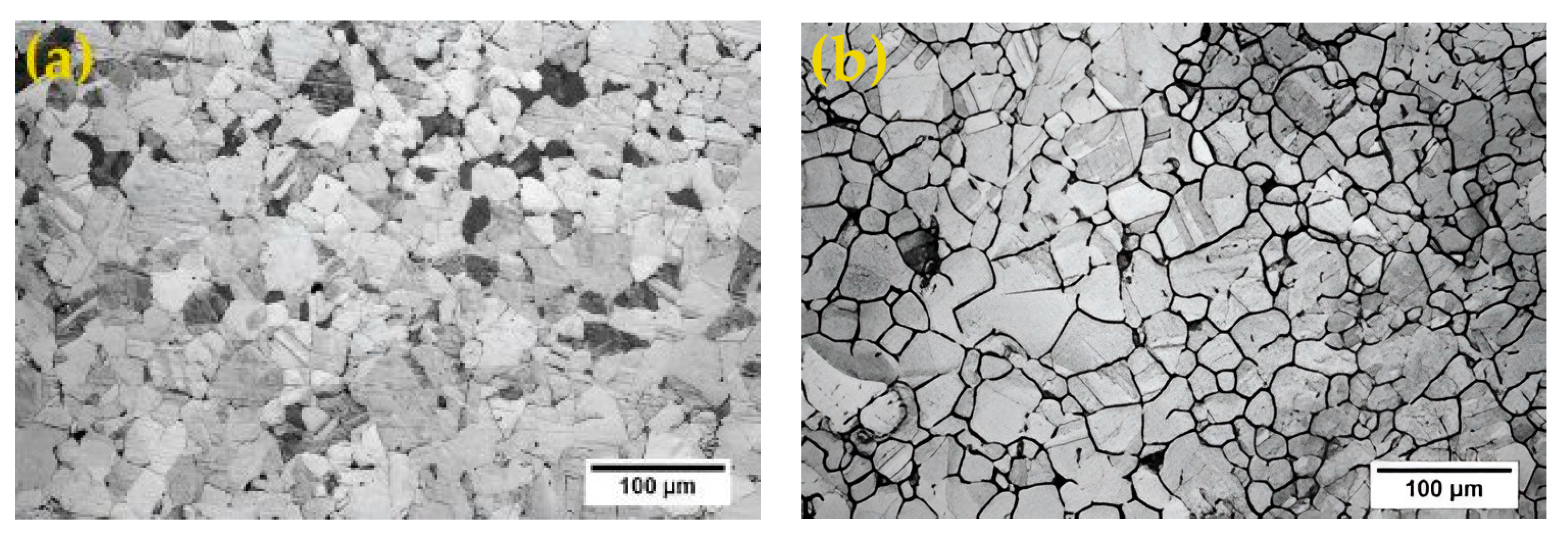
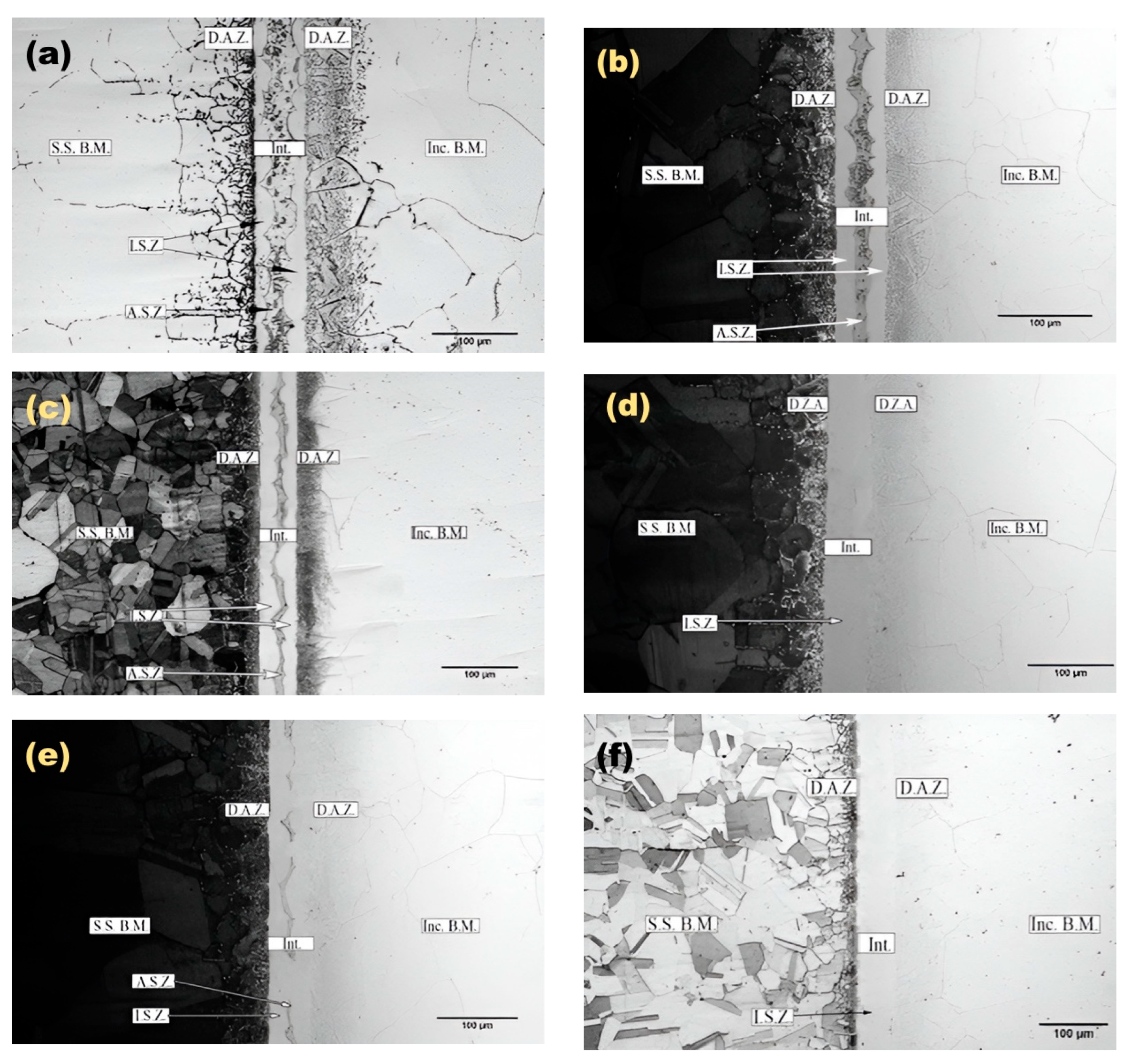
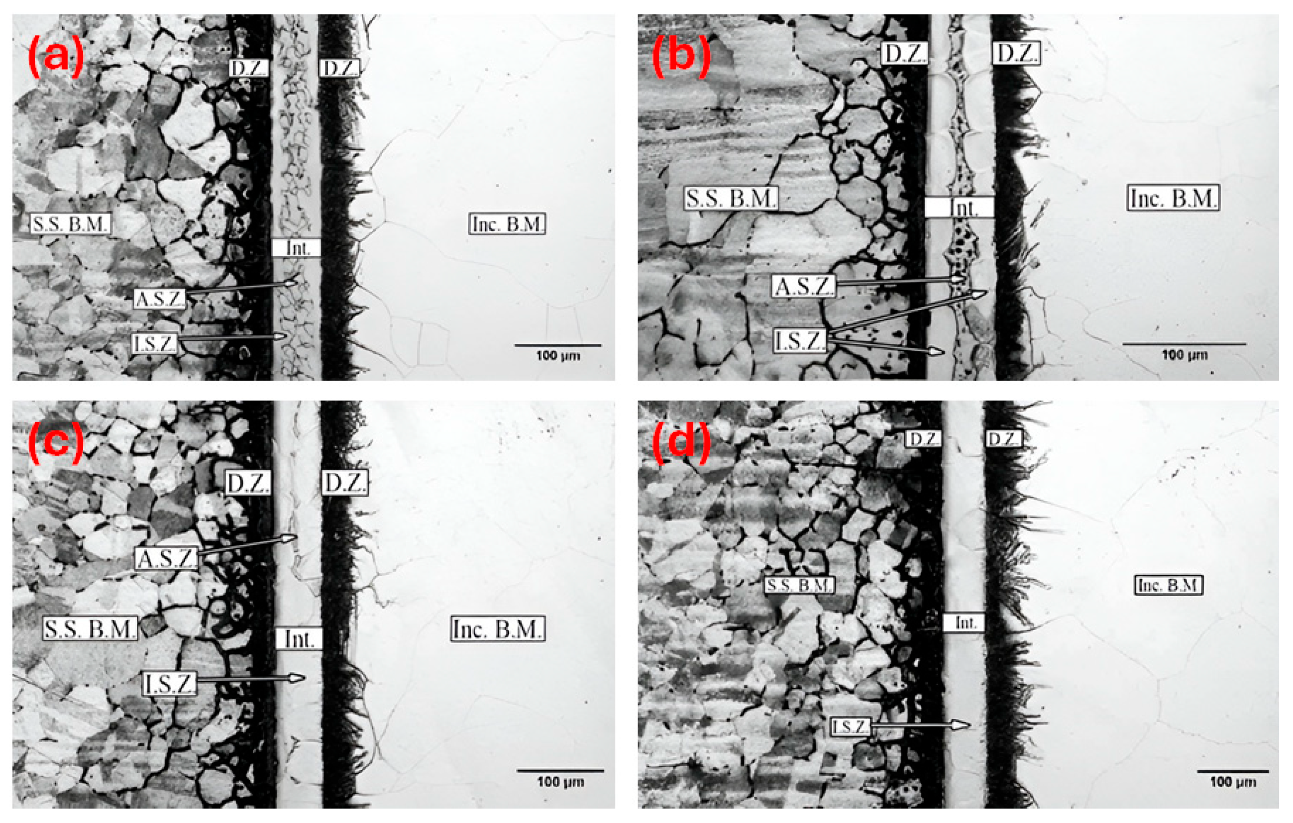
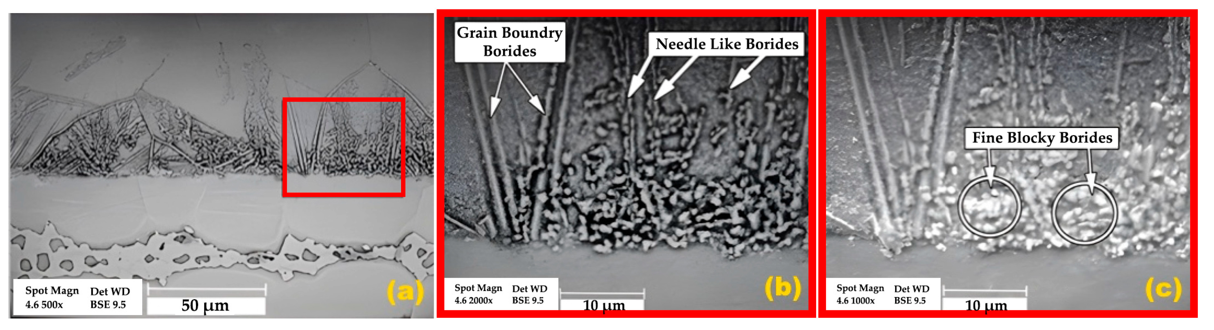
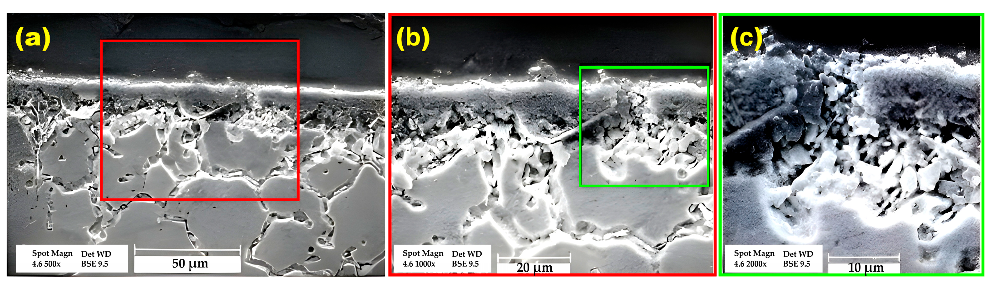
3.1. Microstructural Evolution

Figure 3 illustrates the microstructure of the base materials, stainless steel 310 and superalloy Inconel 617, prior to bonding. The austenitic stainless steel specimens display coaxial grains with an average size of 39 microns, while the Inconel 617 specimen exhibits austenitic coaxial grains averaging 28 microns in size. The coaxial grain structure of these materials is characteristic of their solution-annealed state.
The microscopic images in Figure 4 and Figure 5 illustrate bonded specimens at temperatures of 1050 °C and 1100 °C, captured at different time intervals. Images Figure 4d,e, which represent a specimen bonded for 50 min, demonstrate the threshold of transformation to a microstructure with complete isothermal solidification. However, eutectic phases can still be observed in some areas, indicating that the transformation is not entirely complete at this stage. Figure 4 and Figure 5 consistently reveal that a significant portion of the Inconel 617 base metal consists of coaxial austenitic grains with an average size of 41 microns. In comparison, the steel base metal also contains coaxial austenitic grains with an average size of 48 microns. It is noteworthy that, in agreement with similar studies [23,24], the grain size does not exhibit significant variation with changes in bonding time and temperature.
Figure 4 and Figure 5 reveal a distinct two-phase structure in the interfacial layer zone, resulting from both isothermal and athermal solidification. Building upon previous findings [25], the ISZ comprises a nickel-rich pro-eutectic solid solution known as the γ pro-eutectic phase. In contrast, the ASZ may contain a combination of a nickel-rich pro-eutectic solid solution (γ phase), nickel and chromium-rich boride phases, and nickel-rich silicide phases, contributing to the complex microstructure observed in the interfacial region.
The micrographs in Figure 4 and Figure 5 clearly demonstrate that as the bonding temperature and time increase, the extent of isothermal solidification increases while the eutectic region decreases. Consequently, specimens bonded at 1050 °C for 60 min and at 1100 °C for 50 min exhibit a bonding zone devoid of eutectic phases resulting from athermal solidification. This phenomenon can be attributed to the higher diffusion coefficient of elements involved in eutectic phases, which facilitates their enhanced diffusion into the base metal at elevated temperatures [26]. Figure 6 illustrates the changes in the extent of isothermal solidification as a function of varying bonding time and temperature, providing a comprehensive overview of this microstructural evolution.
Figure 4 and Figure 5 also provide insights into the DAZ, which is influenced by the diffusion of MPD elements from the interfacial layer into the base alloys. A similar study [27], which utilised the BNi2 interlayer for TLP bonding of nickel-based superalloys or stainless steels, identified boron diffusion into the base alloys as the primary factor contributing to the formation of the DAZ. Boron, known for its significantly high diffusion coefficient in nickel and iron, rapidly diffuses into these metals at a relatively high speed, forming intermetallic phases with the elements present in the adjacent alloys. The extent of the DAZ varies between the two base alloys. In nickel-based superalloys, such as Inconel 617, the length of the DAZ ranges from 40 to 80 microns. In contrast, the DAZ in stainless steel alloy 310 is comparatively more minor, varying between 35 and 60 microns. The more extensive DAZ observed in Inconel 617 can be attributed to several factors, including the finer grain structure of Inconel 617, increased grain boundary activity at elevated temperatures, and the higher boron diffusion coefficient in nickel compared to iron [26]. These factors collectively contribute to the enhanced diffusion of boron and the subsequent formation of a more pronounced DAZ in the nickel-based superalloy.
Figure 7 illustrates the microstructure of the TLP-bonded specimen after being heated to 1050 °C for 60 min, followed by a homogenisation process at 1170 °C for 180 min. The homogenisation process aims to reduce concentration differences in the DAZ by decreasing the concentration of various elements, especially MPD elements, to levels below their maximum solubility at ambient temperature. As shown in Figure 7, the boundary between the DAZ and the interfacial layer zone has vanished due to the significant increase in element diffusion during homogenisation. Additionally, the high temperature and extended duration of the homogenisation process have increased the base alloys’ average grain size, with stainless steel 310 reaching approximately 140 microns and Inconel 617 reaching around 120 microns.
EDS analysis was performed to characterise the phases formed in the bonded zones of TLP-bonded specimens. The EDS mapping analysis of the interfacial layer zone reveals the dissolution and diffusion of iron, cobalt, and molybdenum elements from the base alloys into this region. This phenomenon, known as melt-backing of the interfacial layer, has been reported in other studies [8,16] and occurs due to the unequal diffusion rates of MPD elements in the DAZ and incomplete isothermal solidification in short durations, allowing some elements from the base alloys to diffuse into the interfacial layer.
Figure 8 illustrates that the melt-back phenomenon increases with the rise in bonding temperature and duration. However, silicon is only present in the interfacial layer due to its low diffusion coefficient in Inconel 617 and stainless steel 310, even after homogenisation. Some research studies suggest that eliminating silicon concentration requires an extensive homogenisation period (approximately 24 h or more) [28]. Figure 8a shows the concentration of chromium and nickel elements in the DAZ of Inconel 617 and the high concentration of chromium in the DAZ of stainless steel. This phenomenon is attributed to the presence of intermetallic phases rich in these elements in the DAZ regions of the specimens. After homogenisation, as shown in Figure 8b, the concentration of these elements in the intermetallic phases is reduced, leading to a decrease in their overall concentration in the DAZ. The EDS analysis provides valuable insights into the elemental distribution and phase formation in the bonded zones of TLP-bonded specimens. The melt-back phenomenon and the presence of intermetallic phases in the DAZ are important factors to consider when optimising the bonding process and understanding the microstructural evolution of the bonded joints.
Figure 9 presents the results obtained from point and line EDS analyses of specimens TLP-bonded at 1050 °C for 22 min. The figure includes the specimen’s SEM image and separate analysis results for the ASZ and ISZ. Based on the peaks of chromium, silicon, and iron elements in the chart shown in Figure 9a, it can be deduced that the phase present in the ISZ is a solid nickel-based solution with dissolved chromium, silicon, and iron. Similarly, the chart presented for the ASZ in Figure 9b suggests the presence of boride-rich eutectic phases containing nickel, chromium, and silicide. These findings are further supported by the line EDS analyses shown in Figure 9c, which reveal an increase in the intensity of nickel and chromium curves at the centre of the bonded zone.
Figure 10 presents SEM images at various magnifications to observe silicide phases, nickel–chromium borides, and nickel borides in the ASZ of the specimen bonded at 1050 °C for 22 min. The area outlined with a frame in each image is further magnified in the adjacent image. Using the backscattered electron method, where lighter phases appear darker, nickel–chromium boride phases are observed to be darker than nickel borides in Figure 10. The formation of this structure begins with the solid pro-eutectic γ phase at the interface between the molten interlayer and base alloys, which grows while simultaneously rejecting boron and chromium elements to the remaining melt. As the specimen cools, the concentration of the remaining melt reaches the eutectic formation concentration, forming a pro-eutectic solid solution γ and nickel-rich boride. The remaining melt, now high in chromium concentration, undergoes a subsequent eutectic transformation, converting another portion of the melt into eutectic γ and nickel–chromium boride. Finally, as the silicon concentration in the remaining melt reaches a critical point, it undergoes a eutectic transformation, forming a ternary eutectic consisting of γ, nickel silicide, and nickel boride [25,29,30]. These observations provide valuable insights into the complex microstructural evolution that occurs during the TLP bonding process, particularly in the ASZ. The formation and distribution of various phases, such as silicides, borides, and the pro-eutectic γ phase, are crucial in understanding the mechanical properties and performance of the bonded specimen.
The SEM image in Figure 11a shows the TLP-bonded specimen at 1050 °C for 60 min, revealing a microstructure devoid of ASZ and a significantly reduced DAZ. Figure 11b presents the SEM image of the same specimen after homogenisation at 1170 °C for 180 min. As previously mentioned, this image exhibits no visible traces of DAZ or the interfacial layer, indicating that the homogenisation process has effectively eliminated these distinct zones, resulting in a more uniform microstructure across the bonded region.
Figure 12 presents SEM images at various magnifications, revealing three types of boride intermetallic compounds in the DAZ of Inconel 617. The area outlined with a frame in Figure 12a is further magnified in Figure 12b,c. EDS analysis of this specimen, supported by previous studies [10,24], suggests that these compounds likely contain molybdenum, chromium, and nickel. Additionally, the reduced solubility of carbon in the superalloy Inconel 617 may lead to the formation of carbide and carbo-boride phases containing molybdenum, nickel, and chromium. Research suggests that these precipitates initially form at the grain boundaries and subsequently spread within the grains as the bonding time increases [31].
Figure 13 shows the DAZ of the stainless steel 310 specimens, revealing precipitations with needle-like and plate-like morphologies. The area outlined with a frame in Figure 13a is further magnified in Figure 13b,c. The size of these precipitations becomes coarser as the distance from the interlayer–alloy base interface increases. Based on the EDS results presented for this specimen and a review of similar research findings [27], these precipitations are likely carbides, borides, and carbo-borides containing iron and chromium. The formation of carbides in this region is influenced by the role of boron in reducing carbon solubility in iron and promoting its release.

3.2. Mechanical Characterisation

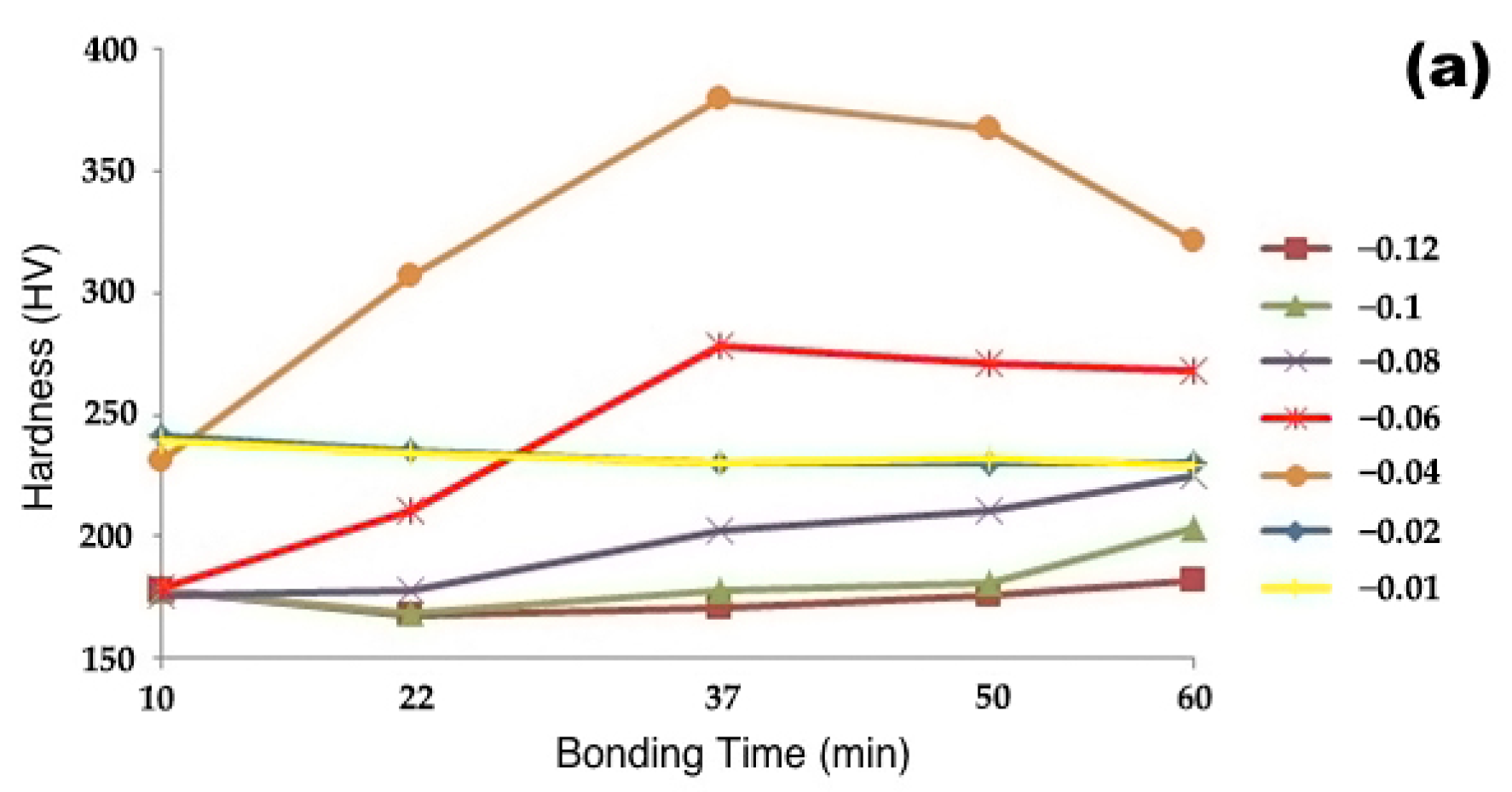
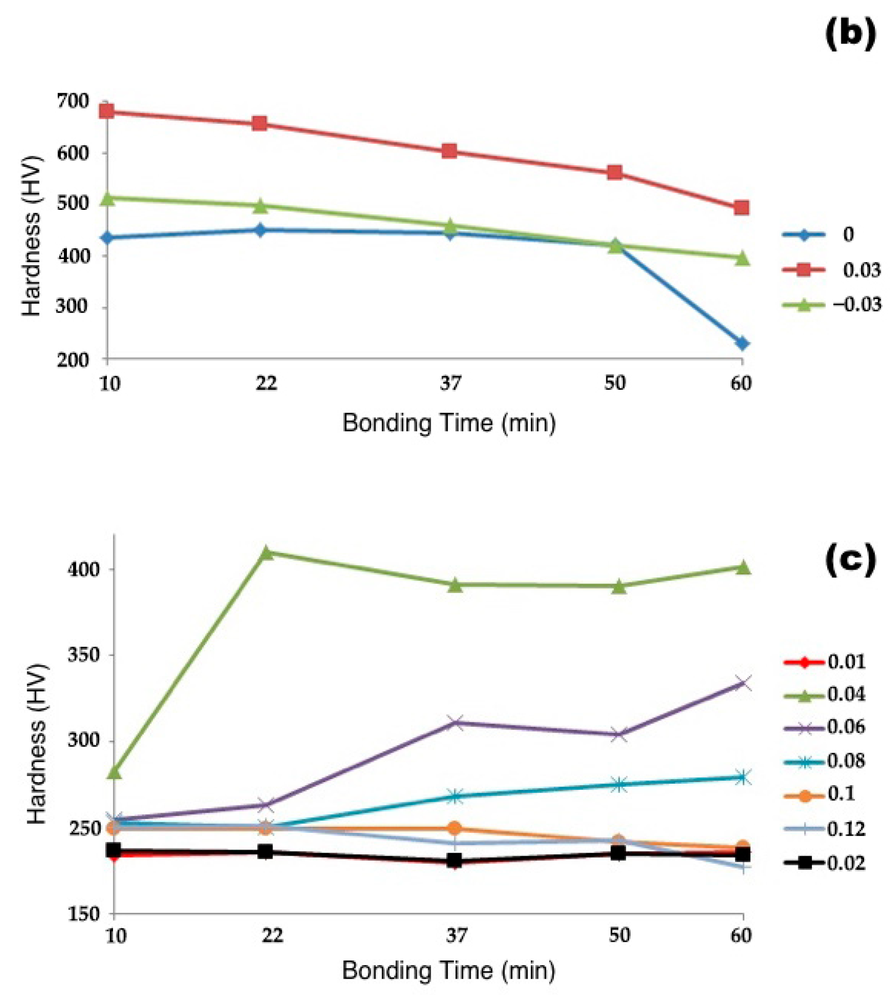
3.2.1. Microhardness

Figure 14 presents the microhardness test results, showing the variations in hardness based on the distance from the centre of the joint at different bonding times. Figure 14a illustrates the hardness variations in the stainless steel 310 range (−0.03 to −0.12 microns), Figure 14b shows the hardness changes in the Inconel 617 range (0.03 to 0.12 microns), and Figure 14c represents the hardness variations in the interface layer (−0.02 to 0.02 microns). According to the chart, at bonding times of 10, 22, 37, and 50 min, the hardness at the centerline of the bonded zone is approximately 430 Vickers. However, at a bonding time of 60 min, the hardness decreases to around 230 Vickers due to the elimination of hard eutectic phases. At a distance of 0.02 microns from the joint centre, all specimens exhibit a hardness of approximately 230 Vickers, which is attributed to the presence of an austenitic pro-eutectic phase resulting from isothermal solidification in these specimens. The hardness at a distance of 0.03 from the centerline (DAZ) is significantly higher than the adjacent zones and gradually decreases with a mild slope as the bonding time increases. This phenomenon is attributed to the increased boron diffusion distance with prolonged bonding time, which reduces the concentration of hard intermetallic phases in this zone [26]. Additionally, this phenomenon causes an increase in hardness in regions that are farther from the interlayer. The microhardness test results provide valuable insights into the hardness distribution across the bonded joint and the effect of bonding time on the hardness profile. The variations in hardness can be correlated with the microstructural changes occurring during the bonding process, such as the elimination of hard eutectic phases and the presence of the austenitic pro-eutectic phase resulting from isothermal solidification. Furthermore, the increased boron diffusion distance with prolonged bonding time plays a crucial role in reducing the concentration of hard intermetallic phases in the DAZ, leading to a gradual decrease in hardness in this region.
Figure 15 presents the microhardness test results of the TLP-bonded sample at 1050 °C for 60 min before and after homogenisation. The figure reveals a uniform trend in hardness variations across all bonded zones after homogenisation, suggesting a homogenised chemical composition and microstructure in various regions of the base alloys. This homogenisation is attributed to the diffusion of boron into different alloy regions, which eliminates its concentration gradient and leads to the dissolution of brittle boride intermetallic phases.

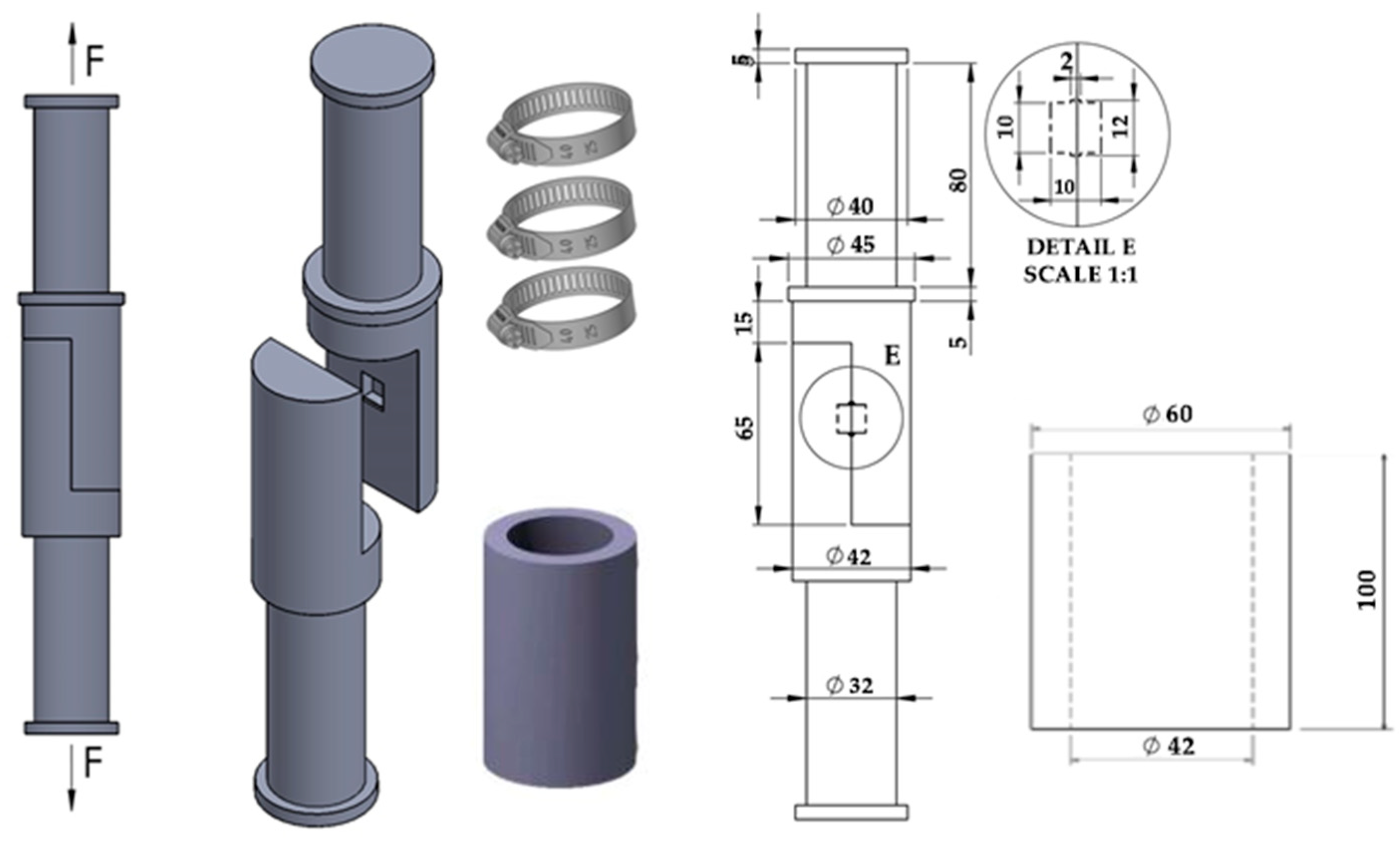
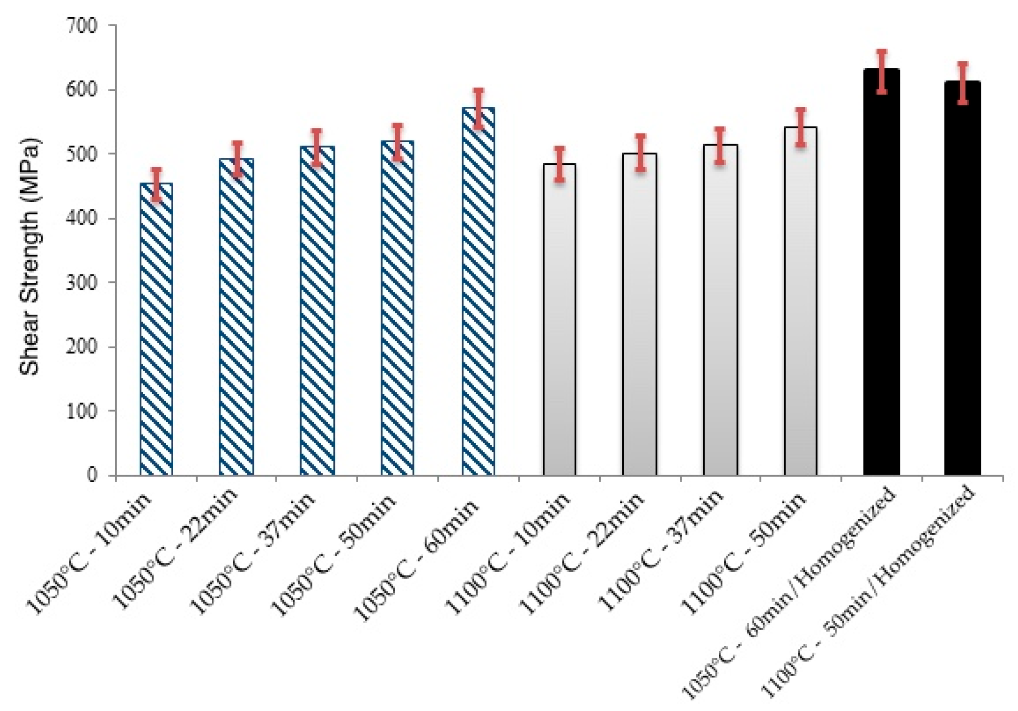
3.2.2. Shear Strength

Figure 16 compares the results of the shear strength tests performed on the bonded specimens. The data reveal that, at a constant temperature, the shear strength of the specimens increases with increasing bonding time. This phenomenon can be attributed to the increase in the ISZ, the reduction in eutectic brittle phases, and the decrease in intermetallic brittle phases in the DAZ. The highest shear strength is observed for the specimen bonded at 1050 °C for 60 min, which subsequently underwent homogenisation at 1170 °C for 180 min. This occurrence is due to the complete elimination of the DAZ and the ASZ in this specimen. The homogenisation process’s high temperature and extended duration effectively eliminate the concentration gradient at the bonding interface, resulting in a specimen devoid of intermetallic phases [29].
Interestingly, Figure 16 also demonstrates that the shear strength of the specimen bonded at 1050 °C for 60 min is higher than that of the specimen bonded at 1100 °C for 50 min. Although both specimens exhibit fully isothermal solidification, the lower shear strength of the sample bonded at 1100 °C is attributed to the increased grain growth that occurs at higher bonding temperatures. These findings highlight the importance of optimising the bonding time, temperature, and post-bonding homogenisation treatment to achieve the desired microstructure and mechanical properties in TLP-bonded joints. Eliminating brittle phases and reducing concentration gradients through appropriate process parameters and homogenisation treatments are crucial for obtaining high-strength bonded joints.

4. Conclusions

This study employed the TLP bonding process to join stainless steel 310 to Inconel 617. The bonding experiments were carried out at temperatures of 1050 °C and 1100 °C, with bonding durations varying from 10 to 60 min. The investigation yielded the following significant findings:
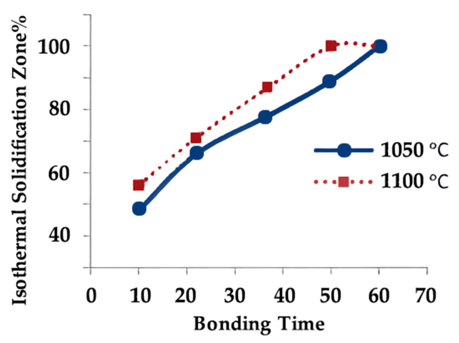
  • Complete isothermal solidification occurred in samples bonded at 1050 °C for 60 min and 1100 °C for 50 min.
  • Increasing bonding time and temperature expanded the isothermal solidification zone, reducing eutectic phase content. Higher temperatures and longer times increased diffusion-affected zone, lowering eutectic phase concentration.
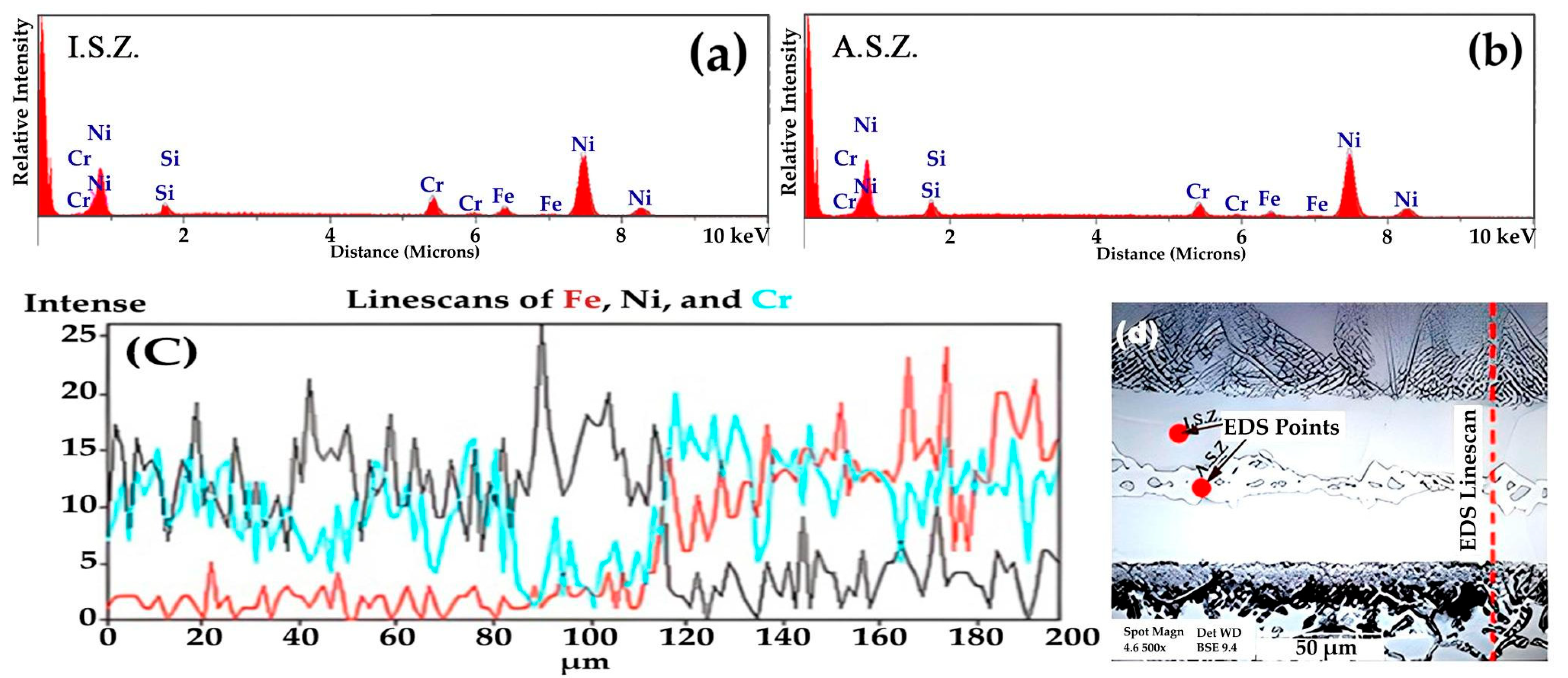
  • The athermal solidified zone contained nickel-rich boride, nickel–chromium-rich boride, silicide phases, and nickel-based solid solution. The isothermal solidified zone is comprised of nickel-based proeutectoid solid solution.
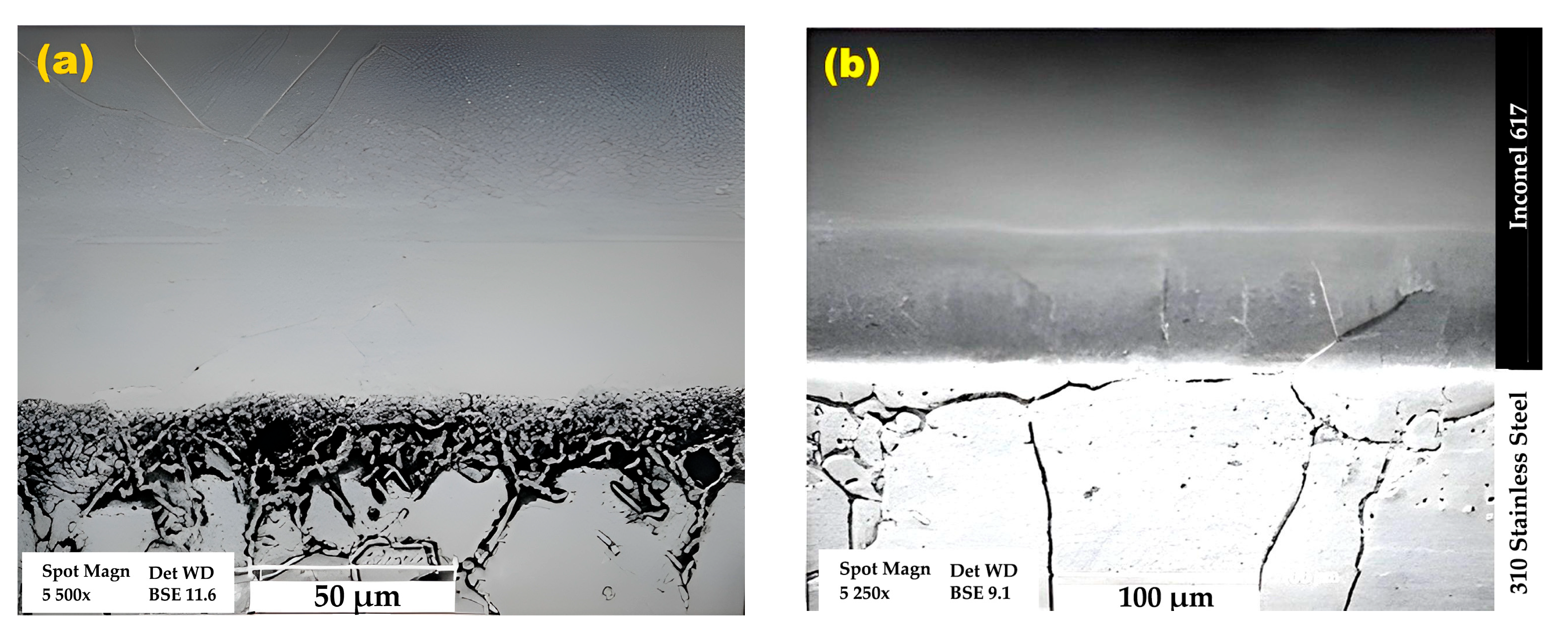
  • Homogenisation treatment eliminated concentration gradients in the diffusion-affected zone, enhancing the mechanical properties of bonded joints.
  • As the bonding time and temperature rose, the rate of hardness variation decreased, and the shear strength of the bonded specimens increased.
This study provides valuable insights into the TLP bonding process of stainless steel 310 to Inconel 617, emphasising the importance of optimising bonding parameters to achieve complete isothermal solidification and minimise detrimental phases. The application of homogenisation treatment effectively enhances mechanical properties by eliminating concentration gradients in the diffusion-affected zone. These findings contribute to a better understanding of microstructural evolution and mechanical behaviour in TLP-bonded joints between these alloys, which can be utilised to develop high-performance joints for various industrial applications. Also, the study acknowledges limitations, including the use of an argon atmosphere and constraints in pressure investigation during bonding. Future research directions encompass long-term performance studies under various operational conditions, the integration of computational modelling with experiments, and specific investigations into fatigue resistance, grain boundary effects, and corrosion resistance of TLP-bonded joints. These proposed areas of study aim to address current limitations and advance the current understanding of TLP bonding in high-performance alloy systems, particularly for Inconel 617–stainless steel 310 joints. The research directions will contribute to developing more robust and efficient joining processes for industrial applications, especially in high-temperature and corrosive environments such as gas turbine components. This comprehensive approach will further enhance the applicability and reliability of TLP bonding in critical industrial sectors.

Author Contributions

Conceptualisation, A.D., R.E., Y.A. and S.L.; methodology, A.D., R.E. and Y.A.; validation, A.D., Y.A. and H.E.; formal analysis, A.D. and Y.A.; investigation, A.D., R.E., Y.A. and S.L.; resources, R.E. and S.L.; data curation, A.D. and Y.A.; writing—original draft preparation, A.D. and S.L.; writing—review and editing, A.D., R.E., Y.A., H.E. and S.L.; visualisation, A.D.; supervision, R.E. and S.L. All authors have read and agreed to the published version of the manuscript.

Funding

This research received no external funding.

Data Availability Statement

The data presented in this study are available on request from the corresponding author. The data are not publicly available because they are part of an ongoing study.

Conflicts of Interest

The authors declare no conflicts of interest.

References

  1. Ganjeh, E.; Kaflou, A.; Shirvani, K. High temperature shear and thermal aging behavior of dissimilar transient liquid phase bonded Hastelloy X to Ni3Al intermetallic compound. Intermetallics 2023, 159, 107916. [Google Scholar] [CrossRef]
  2. Qin, H.; Kuang, T.; Li, Q.; Yue, X.; Gao, H.; Liu, F.; Yi, Y. Stress concentration induced by the crystal orientation in the transient-liquid-phase bonded joint of single-crystalline Ni3Al. Materials 2019, 12, 2765. [Google Scholar] [CrossRef] [PubMed]
  3. Kokabi, D.; Kaflou, A.; Gholamipour, R.; Pouranvari, M. Microstructural Evaluation during dissimilar transient liquid phase bonding of TiAl/Ni-based superalloy. J. Alloys Compd. 2020, 853, 153999. [Google Scholar] [CrossRef]
  4. Alhazaa, A.; Haneklaus, N. Diffusion bonding and transient liquid phase (TLP) bonding of type 304 and 316 austenitic stainless steel—A review of similar and dissimilar material joints. Metals 2020, 10, 613. [Google Scholar] [CrossRef]
  5. Zhang, C.; Shirzadi, A. Fail-safe joints between copper alloy (C18150) and nickel-based superalloy (GH4169) made by transient liquid phase (TLP) bonding and using boron-nickel (BNi-2) interlayer. Metals 2021, 11, 1504. [Google Scholar] [CrossRef]
  6. Sah, I.; Hwang, J.B.; Kim, E.S. Creep behavior of diffusion-welded alloy 617. Metals 2021, 11, 830. [Google Scholar] [CrossRef]
  7. Sun, Z.; Chen, X.; Zhang, L.; Zhang, S.; Feng, J. Experimental and numerical study of transient liquid phase diffusion bonded dz40m superalloys. Crystals 2021, 11, 479. [Google Scholar] [CrossRef]
  8. Zhang, L.X.; Chang, Q.; Sun, Z.; Xue, Q.; Feng, J.C. Effects of Boron and silicon on microstructural evolution and mechanical properties of transient liquid phase bonded GH3039/IC10 joints. J. Manuf. Process. 2019, 38, 167–173. [Google Scholar] [CrossRef]
  9. Farzadi, A.; Esmaeili, H.; Mirsalehi, S.E. Transient liquid phase bonding of Inconel 617 superalloy: Effect of filler metal type and bonding time. Weld. World 2019, 48, 1–11. [Google Scholar] [CrossRef]
  10. Pouranvari, M.; Ekrami, A.; Kokabi, A.H. Transient liquid phase bonding of wrought IN718 nickel based superalloy using standard heat treatment cycles: Microstructure and mechanical properties. Mater. Des. 2013, 50, 694–701. [Google Scholar] [CrossRef]
  11. Lin, Y.; Jiangtao, X.; Yajie, D.; Jin, R.; Junmiao, S.; Jinglong, L. Microstructure and mechanical properties in the TLP joint of FeCoNiTiAl and Inconel 718 alloys using BNi2 filler. J. Mater. Sci. Technol. 2021, 61, 176–185. [Google Scholar] [CrossRef]
  12. AlHazaa, A.; Alhoweml, I.; Shar, M.A.; Hezam, M.; Abdo, H.S.; AlBrithen, H. Transient liquid phase bonding of Ti-6Al-4V and Mg-AZ31 alloys using Zn coatings. Materials 2019, 12, 769. [Google Scholar] [CrossRef] [PubMed]
  13. Gale, W.F.; Butts, D.A. Transient liquid phase bonding. Sci. Technol. Weld. Join. 2004, 9, 283–300. [Google Scholar] [CrossRef]
  14. Duvall, D.S.; Owczarski, W.A.; Paulonis, D.F. Tlp Bonding: A New Method for Joining Heat Resistant Alloys. Weld. J. 1974, 53, 203–214. [Google Scholar]
  15. Malekan, A.; Farvizi, M.; Mirsalehi, S.E.; Saito, N.; Nakashima, K. Holding time influence on creep behavior of transient liquid phase bonded joints of Hastelloy X. Mater. Sci. Eng. 2020, 772, 138694. [Google Scholar] [CrossRef]
  16. Doroudi, A.; Pilehrood, A.E.; Mohebinia, M.; Dastgheib, A.; Rajabi, A.; Omidvar, H. Effect of the isothermal solidification completion on the mechanical properties of Inconel 625 transient liquid phase bond by changing bonding temperature. J. Mater. Res. Technol. 2020, 9, 10355–10365. [Google Scholar] [CrossRef]
  17. Mobarakeh, V.S.; Niroumand, B.; Atapour, M.; Shamanian, M. Effects of Transient Liquid Phase Bonding Time on Microstructure, Mechanical and Corrosion Properties During Bonding of Inconel 617/AISI 310 Stainless Steel. Metallogr. Microstruct. Anal. 2023, 12, 714–729. [Google Scholar] [CrossRef]
  18. Mobarakeh, V.S.; Atapour, M.; Niroumand, B.; Shamanian, M. Effect of Bonding Temperature on Microstructure and Mechanical Properties of Dissimilar Joint Between Inconel 617 and Stainless Steel 310. Metallogr. Microstruct. Anal. 2021, 10, 419–429. [Google Scholar] [CrossRef]
  19. Ghaderi, S.; Karimzadeh, F.; Ashrafi, A.; Hosseini, S.H. Effect of pressure, temperature and homogenisation on the dissolution behavior and mechanical properties of IN718/AISI 304 during transient liquid phase bonding. J. Manuf. Process. 2020, 60, 213–226. [Google Scholar] [CrossRef]
  20. Di Luozzo, N.; Fontana, M.; Arcondo, B. Transient liquid phase bonding of steel using an Fe-B interlayer: Microstructural analysis. J. Mater. Sci. 2008, 43, 4938–4944. [Google Scholar] [CrossRef]
  21. American Welding Society. Brazing Handbook, 5th ed.; AWS: Miami, FL, USA, 2007; pp. 1–19. [Google Scholar]
  22. E92-23; Standard Test Methods for Vickers Hardness and Knoop Hardness of Metallic Materials. ASTM: West Conshohocken, PA, USA, 2023.
  23. Shah Hosseini, H.; Shamanian, M.; Kermanpur, A. Characterisation of microstructures and mechanical properties of Inconel 617/310 stainless steel dissimilar welds. Mater. Charact. 2011, 62, 425–431. [Google Scholar] [CrossRef]
  24. Lin, T.S.; Li, H.X.; He, P.; Yang, X.; Huang, Y.; Li, L.; Han, L. Effect of bonding parameters on microstructures and properties during TLP bonding of Ni-based super alloy. Trans. Nonferrous Met. Soc. China 2012, 22, 2112–2117. [Google Scholar] [CrossRef]
  25. Yuan, X.; Kim, M.B.; Kang, C.Y. Characterization of transient-liquid-phase-bonded joints in a duplex stainless steel with a Ni-Cr-B insert alloy. Mater. Charact. 2009, 60, 1289–1297. [Google Scholar] [CrossRef]
  26. Porter, D.A.; Easterling, K.E.; Sherif, M.Y. Phase Transformations in Metals and Alloys, 4th ed.; CRC Press: New York, NY, USA, 2021; pp. 63–111. [Google Scholar] [CrossRef]
  27. Arafin, M.A.; Medraj, M.; Turner, D.P.; Bocher, P. Effect of alloying elements on the isothermal solidification during TLP bonding of SS 410 and SS 321 using a BNi-2 interlayer. Mater. Chem. Phys. 2007, 106, 109–119. [Google Scholar] [CrossRef]
  28. Cook, G.O.; Sorensen, C.D. Overview of transient liquid phase and partial transient liquid phase bonding. J. Mater. Sci. 2011, 46, 5305–5323. [Google Scholar] [CrossRef]
  29. Pouranvari, M.; Ekrami, A.; Kokabi, A.H.; Han, H.N. Microstructural characteristics of a cast IN718 superalloy bonded by isothermal solidification. Met. Mater. Int. 2013, 19, 1091–1099. [Google Scholar] [CrossRef]
  30. Jalilvand, V.; Omidvar, H.; Shakeri, H.R.; Rahimipour, M.R. Microstructural evolution during transient liquid phase bonding of Inconel 738LC using AMS 4777 filler alloy. Mater. Charact. 1970, 75, 20–28. [Google Scholar] [CrossRef]
  31. Jalilian, F.; Jahazi, M.; Drew, R.A.L. Microstructural evolution during transient liquid phase bonding of Inconel 617 using Ni-Si-B filler metal. Mater. Sci. Eng. 2006, A 423, 269–281. [Google Scholar] [CrossRef]
Figure 1. (a) Description of what is contained in the first-panel schematic of bonded specimens and bonding holder. (b) Schematic of the placement of specimens in the bonding furnace. (c,d) Dimensions of the holder (the images have been rotated 180 degrees to understand the shape of the holder better) [mm].
Jmmp 08 00143 g001
Figure 2. Drawing and schematic of fixture for shear strength assessment [mm].
Jmmp 08 00143 g002
Figure 3. The microstructure of base alloys before bonding: (a) stainless steel 310; (b) superalloy Inconel 617.
Jmmp 08 00143 g003
Figure 4. The microstructure of the bonded specimens at a temperature of 1050 °C and the following times (min): (a) 10; (b) 20; (c) 37; (d,e) 50; (f) 60.
Jmmp 08 00143 g004
Figure 5. The microstructure of the bonded specimens at a temperature of 1100 °C and the following times (min): (a) 10; (b) 20; (c) 37; (d) 50.
Jmmp 08 00143 g005
Figure 6. The changes in the extent of isothermal solidification with variations in bonding time and temperature.
Jmmp 08 00143 g006
Figure 7. Microstructure of the bonded specimen at a temperature of 1050 °C and a time of 60 min after homogenisation at a temperature of 1170 °C for 180 min: (a) bonded zone; (b) Inconel 617 base alloy zone.
Jmmp 08 00143 g007
Figure 8. EDS mapping analyses of the bonded specimen at (a) 1050 °C and of 22 min, and (b) after homogenisation 1170 °C, 180 min.
Jmmp 08 00143 g008
Figure 9. Point EDS and linear EDS analyses of TLP-bonded specimen at 1050 °C and 22 min: (a) isothermal point; (b) athermal point; (c) linear EDS; (d) SEM image.
Jmmp 08 00143 g009
Figure 10. SEM images of the ASZ at different magnifications: (a) 50 µm; (b) 10 µm; (c) 5 µm. Temp: 1050 °C. Time: 22 min.
Jmmp 08 00143 g010
Figure 11. SEM images of a bonded specimen: (a) Temp: 1050 °C. Time: 60 min. (b) After homogenisation. Temp: 1170 °C. Time: 180 min.
Jmmp 08 00143 g011
Figure 12. The SEM images of DAZ of Inconel 617 at different magnifications: (a) 50 µm; (b) backscattered electron image, 10 µm; (c) image of secondary electrons, 10 µm. Temp: 1050 °C. Time: 22 min.
Jmmp 08 00143 g012
Figure 13. SEM images of DAZ of AISI 310 at different magnifications: (a) 50 µm; (b) 20 µm; (c) 10 µm. Temp: 1050 °C Time: 22 min.
Jmmp 08 00143 g013
Figure 14. Microhardness variation influenced by bonding time in different areas of TLP specimens at 1050 °C: (a) stainless steel 310; (b) interlayer zone; (c) Inconel 617.
Jmmp 08 00143 g014aJmmp 08 00143 g014b
Figure 15. Microhardness variation after homogenisation.
Jmmp 08 00143 g015
Figure 16. Shear strength test of bonded specimens.
Jmmp 08 00143 g016
Table 1. Chemical composition of different as-received materials.
MaterialsCCrNiMoMnSiFeTiCoAlNbB
Inc 6170.0622.26Rem8.730.040.020.40.3212.360.870.06-
SS 3100.0925.7420.310.091.40.96Rem-----
BNi20.077.23Rem--4.6-----2.97
Table 2. Details of bonding processes (temperature and time).
Number123456789
Temperature (°C)105010501050105010501100110011001100
Time (min)102237506010223750
Disclaimer/Publisher’s Note: The statements, opinions and data contained in all publications are solely those of the individual author(s) and contributor(s) and not of MDPI and/or the editor(s). MDPI and/or the editor(s) disclaim responsibility for any injury to people or property resulting from any ideas, methods, instructions or products referred to in the content.

