Article

Selective Sheet Extrusion: A Novel Manufacturing Process for Large-Format Material Extrusion

by
Brian Parrott
1,2,*,
Angelica Coronado Preciado
3 and
Eric Feron
1,3
1
Mechanical Engineering Department, King Abdullah University of Science and Technology, Thuwal 23955, Saudi Arabia
2
Saudi Aramco Research and Development Center, Dhahran 31311, Saudi Arabia
3
Electrical and Computer Engineering Department, King Abdullah University of Science and Technology, Thuwal 23955, Saudi Arabia
*
Author to whom correspondence should be addressed.
J. Manuf. Mater. Process. 2024, 8(4), 145; https://doi.org/10.3390/jmmp8040145
Submission received: 6 June 2024 / Revised: 1 July 2024 / Accepted: 3 July 2024 / Published: 5 July 2024
(This article belongs to the Special Issue Design, Processes and Materials for Additive Manufacturing)

Abstract

:
The trade-off between resolution and speed represents a significant challenge when extrusion-based additive manufacturing (AM) is used for large-format additive manufacturing (LFAM). This paper presents an analysis of a new material extrusion process, named selective sheet extrusion (SSE), that aims to decouple these parameters. Unlike traditional single-nozzle material extrusion processes, SSE utilizes a single, very wide nozzle through which extrusion is controlled by an array of dynamically actuated teeth at the nozzle outlet. This allows the system to deposit a selectively structured sheet of material with each pass, potentially enabling the deposition of an entire layer of a part in a single pass. An analysis of the theoretical performance of the SSE technology, in terms of speed and material efficiency in comparison with single-nozzle extrusion systems, predicted speed increases of 2–3 times for the geometries that were explored. The analysis was then validated through experimental work that indicated a normalized improvement in print speed of between 2.3 and 2.5 times using a proof-of-concept SSE prototype. The SSE concept expands the opportunity frontier of LFAM technologies by enabling enhanced print speeds, while maintaining higher resolutions at scale. This enhancement in speed and/or resolution could have significant benefits, especially in large-scale prints that benefit from enhanced internal resolution.

Graphical Abstract

1. Introduction

Additive manufacturing (AM) technology is transforming manufacturing across various industries owing to its increasing accessibility, reliability, and versatility. Moreover, AM offers the potential for reduced costs, shorter lead times, and decreased waste [1]. Significant advances have been made in increasing the capabilities of AM by demonstrating multi-material and/or multi-process systems that enable increases in both geometric and functional complexity, primarily at desktop scales [2,3]. Additionally, with the expiration of patents on many of the original AM technologies, a robust ecosystem of affordable desktop 3D printers has emerged, further increasing accessibility and innovation [4]. While AM technologies are traditionally used for prototyping, direct use of printed parts is becoming equally common [5], with industries such as the space-launch sector relying heavily on AM to enable rapid innovation, trial and error, and flexibility in complex, high-performance parts such as rocket engines [6,7]. With the relatively high costs of AM on a per-part basis when compared with mass manufacturing technologies such as injection molding or casting, economically feasible use cases generally rely upon a need for customization, a short turn-around, or unique geometries to allow AM technologies to compete with traditional technologies in end-use applications. Still, as AM technologies continue to improve, the barriers to effective utilization continue to decrease, enabling further opportunities for AM technologies to transform multiple industries [8]. The core contribution of this paper is to provide an analysis of the SSE process and show how this new process addresses one of the challenges in large-format additive manufacturing (LFAM) and enables additional use cases by enhancing speed and/or resolution while maintaining material efficiency. The following sections provide further context to frame the SSE technology by introducing LFAM in more detail, as well as highlighting challenges and potential solutions related to AM at large scales.

1.1. Large-Format Additive Manufacturing

LFAM represents an opportunity for both significant growth and impact. The lead article for a recent special issue highlighted both the significant potential of LFAM to address the needs of industries such as energy and construction, which often require customization and/or the production of small quantities of very large parts, as well as the need for the continued advancement of the technology [9]. Three key properties relevant to AM technologies were highlighted: speed, size, and material cost, defining that LFAM should have build rates exceeding 1000 cm 3 / h , for volumes greater than 1 m 3 with material costs under $20 per k g . In practice, LFAM technologies such as 3D concrete printing have already exceeded most of these criteria by an order of magnitude [10].
While multiple companies and teams have developed extrusion-based LFAM technologies, the BAAM (Big Area Additive Manufacturing) system at Oak Ridge National Laboratory/Cincinnati Incorporated is well represented in the literature by multiple studies specifically focused on LFAM, including diverse topics such as infrared preheating to improve interlayer strength [11], real-time defect correction [12], and design tips for large-format AM using carbon-fiber-reinforced thermoplastics [13]. However, one of the key challenges highlighted has been the trade-off between speed (volume deposition rate) and resolution (minimum feature size/surface finish) [9,14,15]. To elucidate this challenge explicitly, Chesser [14] presented an empirically supported mathematical model in which the flow rate increases with the square of the nozzle diameter, meaning that a doubling of nozzle diameter yields approximately four times the flow rate of material. While the quadratic nature of this trade-off yields significant increases in deposition rates as the nozzle sizes increase, the volume of large objects increases at an even faster cubic rate as their scale increases. As such, LFAM systems must use relatively larger nozzles to maintain reasonable speeds as objects scale up dramatically. While some research has highlighted an increased part strength when using larger nozzles [16], these larger nozzles also yield reduced resolution (larger minimum feature size), which can create significant geometric deviations and the need for special considerations in the design of parts and the processes used to print them [13]. Additionally, with the loss of geometric complexity resulting from the use of larger nozzles, the utility of parts can be negatively affected as their features become less precise [14] and the material efficiency generally achieved with additive processes [17] can be lost.
While this trade-off between resolution and speed is inherent in single-nozzle material extrusion systems [18], it does not show up in a variety of other AM systems, such as multi-jet fusion, where an entire row of ink-jet-like nozzles are used to selectively dispense binder and detailing agents across the width of the build platform [19], or digital light processing, in which a projector selectively solidifies voxels (3D/volumetric pixels) via photopolymerization across an entire layer simultaneously. However, most of these processes are not easily applicable to the largest examples of LFAM due to the way they solidify materials in a bed or vat, rather than extruding or placing material in a free-form fashion. A recent review article highlighted many applications of binder jet 3D printing in the construction industry, with multiple technologies showing LFAM techniques that involve parallelization of binder jetting across a wide bed [20]. However, the size of the print bed limits the size of objects that can be printed using binder jet technology. Additionally, the objects must be removed from the system after the print and, therefore, cannot be built in place. In light of these challenges, reviews of AM strategies have generally identified material extrusion techniques as the best suited for in-place LFAM [8,21]. As such, it is useful to focus on the efforts being made to overcome the trade-off between resolution and speed faced by material extrusion LFAM processes.

1.2. Overcoming the Trade-Off between Resolution and Speed

Many teams have developed strategies to address the trade-off between resolution and speed faced by material extrusion AM systems. While larger diameter nozzles and layer heights can increase the strength of the printed material [22,23], larger nozzles also decrease geometric accuracy and the ability to print finely detailed features. To address the surface roughness associated with the use of a large-diameter nozzle, a team working with the BAAM system developed a dual-diameter nozzle (dual-port nozzle) that can be switched from extruding through a large diameter to a smaller diameter nozzle when finer resolution is needed [14]. This improvement allows a single machine to print at two resolutions, thereby improving print quality where needed, while still maintaining higher flow rates for the rest of the print. The author of the article highlighted that this solution is ideal in cases where fine resolutions are only needed for small portions of the print, such as a single critical surface in a mold. However, this solution does not resolve the challenge caused by the higher-resolution nozzle’s lower print speed when enhanced resolution is required throughout the print. In another case, a team of researchers sought to use variable-width extrusion to print at multiple resolutions with a single nozzle by changing the flow rate during printing to increase or decrease the width of the deposited bead [24]. The work’s primary goals were to reduce delamination and air cavities caused by extra layers in variable-width cross-sections, while printing at an increased rate and with functionally enhanced resolution in variable-width cross-sections. While their work showed some promise for optimizing the trade-off between resolution and speed, this method does not eliminate the trade-off nor does it enable internal structuring with high resolution. As an alternative, some teams have explored the use of multiple nozzles to accelerate 3D printing processes, though many of these nozzle arrangements primarily seek to enable faster multiple-material printing [25]. Unfortunately, while using multiple, parallel nozzles can increase the effective print rate of a system [26], this technique also introduces additional anisotropy compared to using a single, larger nozzle, due to the increased number of material discontinuities created between each of the parallel extrusions. Such anisotropy can significantly impact the mechanical performance of a structure, especially in the case of the fiber-reinforced materials often used in high-performance AM [27].
Instead of using multiple nozzles to increase the effective resolution of the print without losing speed, some researchers have attempted to shape the extruded material during deposition to enhance the surfaces of the print. For example, in a process called contour crafting, one or more trowel-like devices are used to smooth out the surface of the material, thereby minimizing the appearance of distinct layers or other defects that become more obvious with larger nozzle sizes and increased layer heights [28]. Rather than using a shaping tool attached to the nozzle, a team from Singapore developed a variable-geometry nozzle in which material is extruded through a large outlet that can change its internal shape to more closely match the desired curve of an exterior surface [29]. The team demonstrated that this method could be used effectively to increase the resolution of the surface in the vertical direction. However, while this method can dramatically increase the geometric accuracy of vertically curving surfaces without significantly reducing extrusion volume, it does not enable internal structuring (hollow spaces inside of a print) with a higher resolution.
The efficacy of a material extrusion process that seeks to improve the trade-off between resolution and extrusion speed is presented in this article. This new process, termed selective sheet extrusion (SSE), is designed to enable higher-resolution printing in both the external and internal portions of a print, while achieving a significantly higher print speed relative to a single-nozzle system with equivalent resolution. SSE is believed to show particular promise for the biggest LFAM projects—such as those in building and construction—where the sizes of industrial nozzles range in width from 3 to 10 cm [30]. The concept offers an alternative to the use of larger nozzles, as manufacturers and end-users might otherwise seek to enable faster print speeds despite the associated loss of resolution.
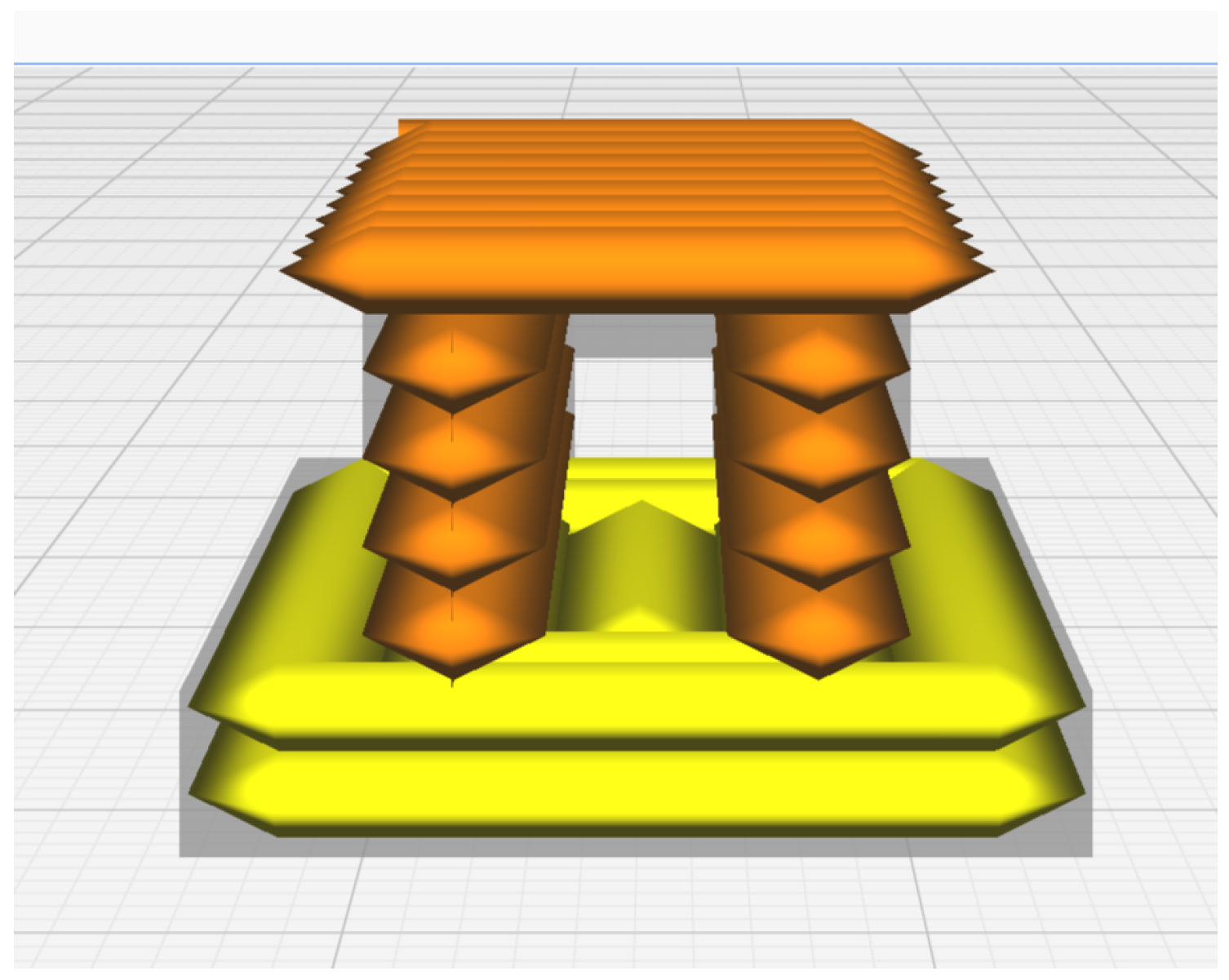
SSE builds upon the basic design of a sheet extruder but mounts the extruder onto a motion system (e.g., a gantry) and adds individually actuated, thin cutting blocks across the width of the nozzle. These thin cutting blocks act much like teeth, as they are actuated vertically to selectively cut off or allow material flow across specific sections of the outlet, as shown in Figure 1. Because of this similarity in function, these elements are referred to as teeth for clarity of function in the rest of this paper. By activating the teeth to open only when and where material deposition is desired, SSE parallelizes the print process, while simultaneously reducing the anisotropy highlighted by Panda [27]. This reduction in anisotropy is realized as a result of how the material is extruded as a single piece across any contiguous set of open teeth up to the full width of the nozzle, which reduces the number of intralayer discontinuities. This new process enables higher dimensional accuracy, approximated by the width of each of the actuated teeth, while maintaining a high material deposition rate proportional to the entire outlet’s cross-section. By changing the width of the teeth and/or the number of teeth to fit the desired application, SSE is designed to overcome the quadratic trade-off between resolution and speed that otherwise governs single-nozzle material extrusion processes. This new process has significant potential to contribute towards more cost-effective LFAM in sectors such as building and construction by enabling higher resolution prints without sacrificing the speed necessary to complete extremely large builds within a realistic timeframe. The higher resolution of the process could also result in significant material savings by enabling optimized geometries, as explored in the theoretical analysis that follows.

2. Theoretical Analysis

This section presents a theoretical analysis of the performance of a generalized SSE system vs. traditional single-nozzle systems of similar resolution. The full set of assumptions, calculations, and detailed results of this analysis are included in Appendix A to maintain brevity in the main text. In brief, a model for the extrusion rate of the SSE system was created by extending a previously published model relating nozzle diameter with extrusion speed for single-nozzle extrusion-based systems [14]. This extended model was then used along with the original model to compare the performance of a generalized SSE system and a typical single-nozzle system in printing various geometries relevant to LFAM, especially considering applications in the building and construction industry. In addition to exploring the comparative performance of an SSE system, the details captured in Appendix A provide value to the community in the form of a generalized methodology for comparing the performance of various printing technologies, with an emphasis on their relative speed and material usage in printing a given geometry.

2.1. Analytical Process

The basis of the analysis relies upon the experimentally-validated model for comparing nozzle diameter and extrusion rate presented by Chesser [14]. Rearranged to elucidate the effect of nozzle diameter on the volumetric flow rate of a single-nozzle system, Q single , as shown in Equation (1), it is observed that the volumetric flow rate varies linearly with v, the nozzle velocity, and quadratically with d, the nozzle diameter. The volumetric extrusion rate can then be described as
Q single = v d 2 2 .
This model can be adapted to the SSE system. The original model effectively multiplies the cross-section of the extruded bead emerging from the nozzle by the nozzle velocity, which is assumed to be constant. As such, the model can be adapted to the SSE system by recognizing that each tooth can be modeled as a nozzle with a diameter (and resolution) equal to the width of the tooth, w t , and that the effective flow rate of each tooth can then be multiplied by the number of teeth, n t , to realize the full extrusion potential of the SSE system. The current SSE system is designed to maintain the same aspect ratio assumed by Chesser, in which the extruded layer height is half the width of the nozzle or tooth. As a result, it is possible to replace the diameter, d, from Equation (1) with the tooth width, w t , and then multiply the result by the number of teeth, n t , to determine the flow rate of the SSE system. The volumetric extrusion rate of the SSE system, Q SSE , can then be modeled as
Q SSE = v w t 2 2 n t .
Using these models, the performance of a typical single-nozzle system and a generalized SSE system was compared across three geometries. These three geometries consisted of a simple box; a wall structure following a pattern similar to a concrete masonry unit, called a DCMU (digital concrete masonry unit); and a conduit structure. In the first example, no internal structuring is required. In the second example, the DCMU, internal structuring (the hollow sections inside each repeating unit) is allowed, but not required. In the third example, the conduit, an internal structure is required and the use of larger nozzles thus results in the overall width of the printed structure increasing. The orientation of the void in the conduit is horizontal rather than vertical, however, this does not dramatically affect the analysis.
The results presented in the body of this paper focus on the relative speed of manufacture between SSE and single-nozzle systems, which was also the focus of the experimental validation. However, it is worth noting that the theoretical analysis also includes an investigation of the material efficiency of the two systems at various resolutions. These results will be presented briefly for the DCMU geometry alone, but more details are included in Appendix A.

2.2. Results of Analysis

This section presents a summary of the results of the theoretical analysis of the performance of the SSE system in comparison with a traditional single-nozzle system. The focus of this section is on the predicted increase in relative print speed given systems of matching resolution using either the SSE concept or the traditional single-nozzle design. The results are summarized in a table, and a resulting formula is presented that serves to predict the relative speed increase of the SSE system. A brief overview of the predicted increase in material efficiency is also presented. However, that section is kept brief, as this is not the primary focus of the presented theoretical analysis and experimental validation.

2.2.1. Predicted Increase in Speed

Table 1 presents an overview of the results from the theoretical analysis. The table captures the ideal tooth count for each geometry (to achieve material efficiency at the highest speed) along with the geometry’s fill factor (amount of the volume that is filled) of each geometry. The table then highlights the relative print speed achievable by an SSE system in comparison with a traditional single-nozzle system with the same resolution (nozzle size matching the width of each tooth). Details of all the geometries and calculations used to achieve these results can be found in Appendix A.
Although the maximum flow rate of the SSE system increases linearly with the number of teeth of a given size, this does not translate directly into print speed, as it does not account for voids (unprinted areas) in the geometry. Within the results presented above, a relationship emerges in which, for a given print resolution, the relative speed of the SSE system, S SSE , can be calculated as
S SSE = n t F F ,
where n t remains the number of teeth in the SSE system, and F F is the fill factor of the geometry to be printed. This relationship becomes clear by considering that when the fill factor is 1, the proportionality between Equations (1) and (2), representing the maximum flow rate, is n t and that the maximum flow rate of the SSE system is reduced proportionally when some of the teeth are closed, such as during the extrusion of a layer with voids.
While Equation (3), describing the relative speed of SSE systems in comparison with single-nozzle systems with the same resolution, does not enable the comparison of various resolutions in terms of material efficiency, nor directly enable the calculation of print times, it provides a convenient method of estimating the benefits of using an SSE system in terms of accelerated print times when compared with a single-nozzle system with the same resolution.

2.2.2. Predicted Increase in Material Efficiency

While the focus of this paper is on the potential for SSE to increase the speed of printing at a large scale without sacrificing resolution, the theoretical analysis also considers the material efficiency of the systems based on the resolution of the printer. Using a larger nozzle diameter on a single-nozzle system will lead to faster print speeds; however, the reduced resolution may not only reduce the quality of the surface finish and detail of the printable geometries but may also decrease material efficiency in cases where the diameter of the nozzle is larger than the minimum feature thickness. While this does not often occur at desktop scale, since the resolution of the system is usually multiple times that of the thinnest feature, it is common in the field of LFAM for the width of a geometrical feature—such as the surface layer of a wall—to be that of the nozzle diameter. As a result, a larger nozzle, chosen to increase overall print speed, could lead to significant increases in the material used and resultant increases in both cost and environmental impact.
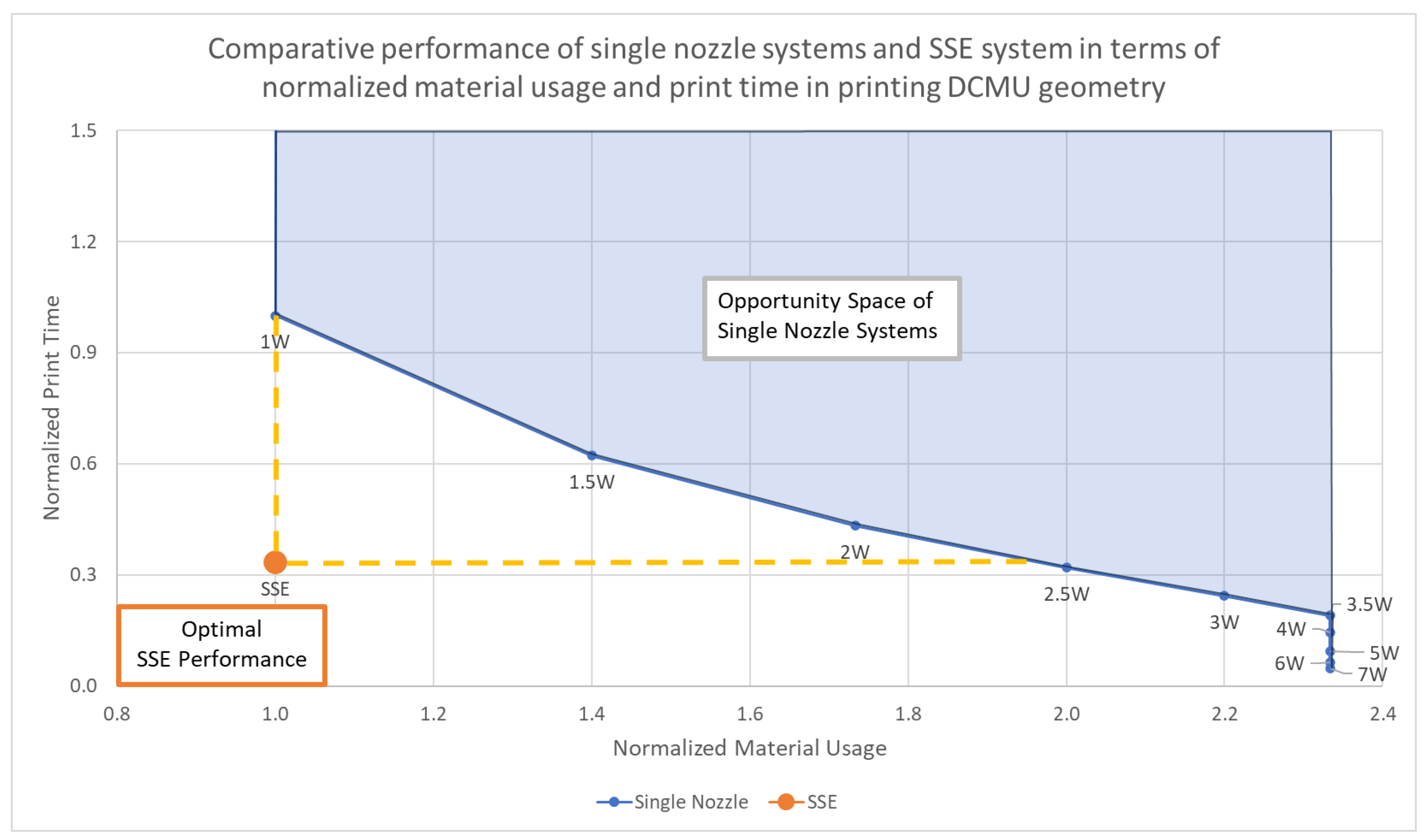
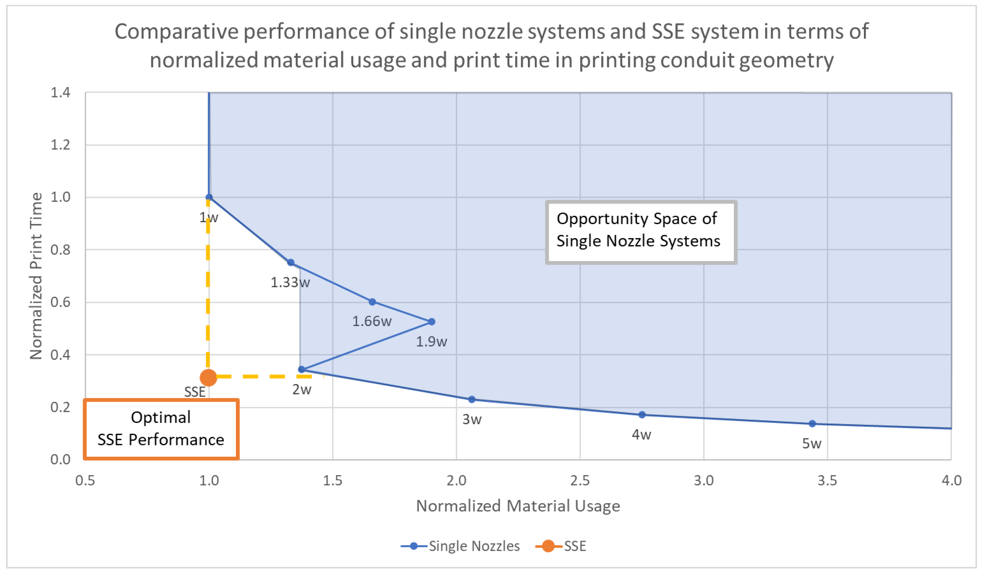
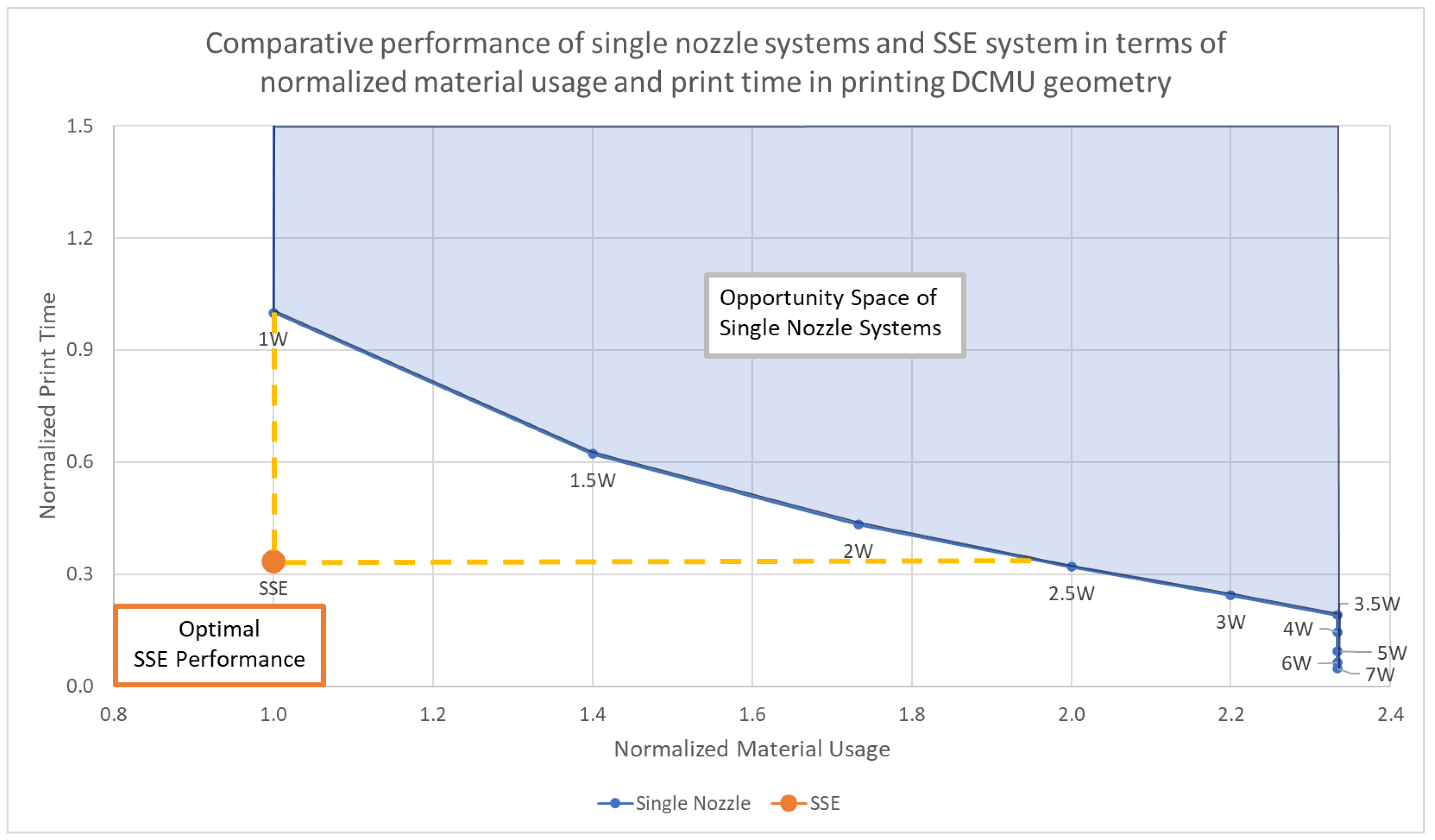
For example, when examining the DCMU geometry, which represents a potential design for the wall of a building, significant opportunities for SSE technology to improve material efficiency can be observed. Figure 2 shows a plot of the normalized print time of the systems vs. the normalized material usage, in which the overall technology performance is improved by moving towards the lower-left quadrant that represents high speed and efficient material usage. The blue region represents the opportunity space of single-nozzle systems printing the DCMU geometry, while the performance of an optimal SSE system is shown as the orange dot, which exceeds the opportunity frontier of single-nozzle systems. The dashed yellow lines show how the SSE system compares to single-nozzle systems with the same material usage or print time.
For this DCMU geometry, Figure 2 shows that a system would have to use a nozzle diameter over two times larger to reach the same speed as an SSE system. In doing so, the thickness of each section of the wall would increase proportionally, ultimately requiring nearly twice the volume of material to print the structure. While there is hope that LFAM has the potential to reduce the environmental impact of the building and construction industry through optimized material use [17,31], this will be far more difficult if the processes used do not allow for efficient geometries to be printed.

3. Experimental Validation

Having developed and explored theoretical models to predict the comparative performance of the SSE technology with single-nozzle systems, this section aims to validate the results of the theoretical section, specifically the outcome captured in Equation (3), by comparing the true print time of an SSE prototype with that of a commercially available printer that utilizes a single nozzle. The design of the prototype SSE system is explained in detail, followed by an overview of the commercially available printer used to compare the actual performance. The experimental design is followed by the results of the experimental validation.

3.1. Selective Sheet Extrusion (SSE) System

The first sections of this paper introduced and then theoretically explored the selective sheet extrusion (SSE) technology to understand whether SSE can effectively overcome the trade-off between resolution and speed experienced by single-nozzle systems. Following the theoretical exploration of the SSE technology’s ability to extend the capabilities of LFAM technologies presented in Section 2, a laboratory-scale prototype system capable of printing small demonstration structures similar to those presented in the previous section was developed. While still being optimized, this SSE prototype enabled experimental investigation of the theoretical results, and currently uses clay as the extrudate. For this investigation, the SSE prototype was compared with a similarly sized, commercially-available single-nozzle 3D printer also designed to print with clay. While the nozzle on this commercial system is smaller than the tooth width of the SSE prototype, no lab-scale system with an appropriately large nozzle was identified, and Chesser’s model [14] gives a means of fairly comparing the two systems despite the difference in nozzle size. Each system printed a tunnel structure that contained features similar to the geometries discussed above, and the time to print was recorded for analysis and validation of the theoretical results.
In the laboratory prototype shown in Figure 3, the material is extruded by a plunger mechanism actuated via a 12 V Nema 23 stepper motor coupled with a reducer gear (plunger drive system), both part of a ceramic printing conversion kit (Eazao). The stepper motor raises and lowers the plunger mechanism, which is concentric with an elliptical material cavity filled with the extrudate—clay in this case. The unmodified clay is wetted and mixed to a soft consistency so it can be handled and extruded without significant cracking or tearing, while retaining a firm consistency (not liquid) to prevent deformation of the print after deposition. The bottom of the material cavity is sloped towards the nozzle outlet, which is situated at the bottom of the print head assembly and consists of a rectangular opening that is 15.4   c m wide and 1 c m tall and pointed 10 degrees below the horizontal. Seven linear actuators are positioned above the nozzle opening with bipolar operation. An applied voltage of 12 V can raise or lower the attached teeth depending on the polarity sent to each actuator. These actuators are controlled through a set of 14 single-pole, double-throw relays, which enable 14 digital output lines from an NI MyRio, to control the teeth with two relays for each tooth, allowing the system to raise, lower, or disable each tooth independently in coordination with the movement of the gantry system. The teeth are each 2.2   c m wide and 1.2   c m deep, with a chamfer on the bottom of the front edge to reduce the amount of material displaced when closing the teeth. The gantry system was built using an open-source CNC Kit (Lead 1010, OpenBuilds) with a vertical extension to fit the large print head assembly.
This system is designed to enable an extrusion width of 15.4   c m with 2.2   c m resolution across the width of the nozzle (x-axis) and a layer height (z-axis) resolution of 1 c m . Due to the depth of the teeth during the cutting motion, the resolution in the extrusion direction (y-axis) is approximately 1 c m . However, issues with layer attachment sometimes occur if only small pieces of clay are extruded or at the beginning of extrusion. In these cases, especially at the beginning of extrusion, this can result in upward curling of the deposited clay as it sticks to the nozzle rather than the layer below due to the shallow angle of extrusion in this prototype. To conduct the experiment, this issue was fixed by pressing the clay gently to align it with the layer below, being careful not to otherwise modify the structure or surface of the clay. Overall, the SSE system design targets a resolution similar to a 2.2   c m diameter nozzle, while extruding at a maximum flow rate that is approximately seven times that of an equivalent-resolution single-nozzle system.
For the experiment, the SSE nozzle’s linear print speed was maintained at 1.5   cm s 1 , while the non-printing movement speed was 2 cm s 1 . The limitation of printing speed was experimentally determined and was slowed, primarily due to limitations in the power of the extrusion drive system, which limited the maximum extrusion speed achievable when all teeth are open and maximum flow is required. While print speeds could have been increased during portions of the print without full-width extrusion, the printer was programmed to maintain a constant print velocity to avoid complications in the comparison of results.

3.2. Commercial Clay 3D Printer

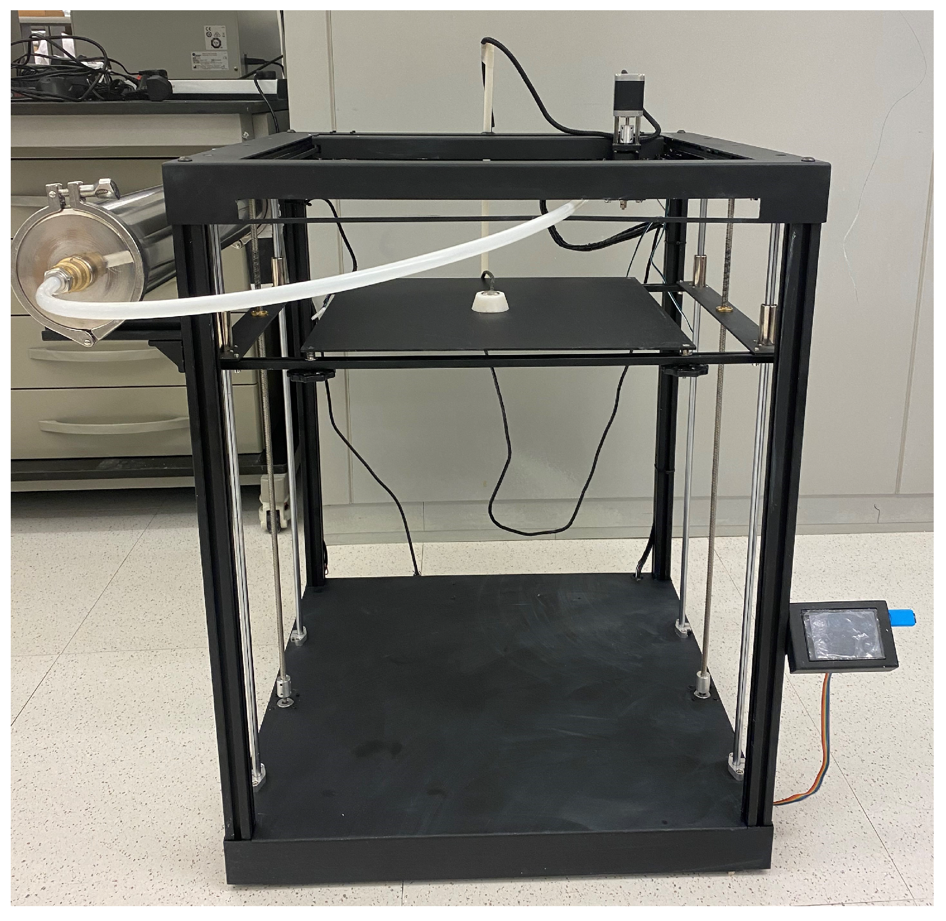
For the purposes of comparing the SSE system with a commercially available—and roughly equivalent—clay 3D printer, the Eazao Matrix M600 was selected (Matrix M600, https://www.eazao.com/product/matrix-m600/, accessed on 6 June 2024). This system, shown in Figure 4, is a gantry-based system with a build volume of 40 cm × 40 cm × 60 cm that is designed to print with clay and other similar materials. While its nozzle sizes do not reach the 2.2   c m equivalent of the SSE system, it uses relatively large nozzles of up to 3.3   m m in diameter, which could be scaled as discussed in Section 3.1 to evaluate the comparative performance of the two systems in printing the same object. This printer uses the same extrusion drive system (motor, drive, and gearbox) that was adapted to be used in the SSE prototype, thus representing a very comparable single-nozzle system.
The print settings used in preparing the print were the default settings for the printer and nozzle as per the product manual. Of note, the recommended linear print speed of the nozzle is 2.5   cm s 1 , meaning that it moves nearly twice as fast as the current print speed of the prototype SSE system. To ensure alignment with the model and to ensure complete infill, the line width was selected to match the nozzle diameter of 3.3   m m , and the layer height was set to 1.6   m m . Additionally, the bottom layer setting was overridden for the surface spanning the top of the tunnel and the infill parameter was set to lines, with alternating orientations of 0 degrees and 45 degrees, to increase the ability of the printer to span the gap at the top of the tunnel without support.

3.3. Experimental Design

To validate the theoretical results presented in Section 2.2.1 related to the speed of printing, it was necessary to show that actual print times aligned with the theoretical results. Towards this end, the SSE system and commercial system were used to print the same geometry. The commercial system printed one model at the same scale as the SSE system and the same model with its size scaled by the relative size of the system’s nozzle diameter. The time to complete the prints was monitored and recorded. Before printing, most modern slicers report an estimated print time, and so this time was recorded, along with a predicted print time for the SSE system based upon the GCode written to control the SSE system. The actual print times were recorded by video in the case of the SSE system and the smaller model printed by the commercial system (due to their shorter duration), while the start and stop times were recorded for the commercial printer. As a result, the first two print times were measured to the nearest second, while the commercial system’s full-scale print time was measured to the nearest minute. Based on the chosen geometry and anticipated print times, these methods of time-keeping yielded approximately the same relative precision for the three prints.
During the SSE print, the system was stopped after the first two layers to perform a material change for aesthetic reasons, to create the appearance of a structure resting on a printed foundation. However, all systems were returned to the same positions to ensure that this pause did not compromise the integrity of the calculated print time.

3.3.1. Three-Dimensional Model for Experimental Comparison

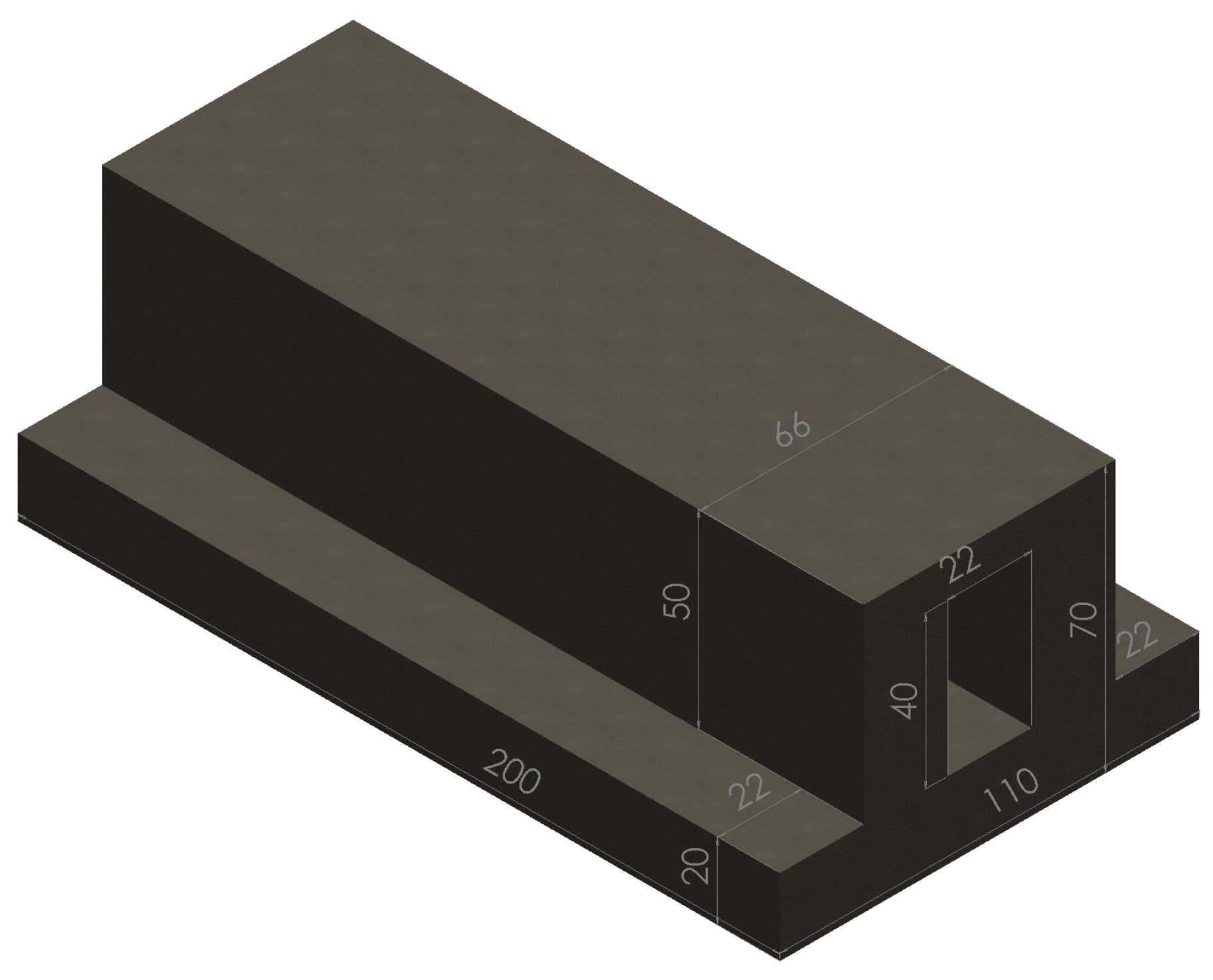
While the theoretical section focused on simple geometries with indeterminate length and/or height, the experimental print was designed to capture a realistic combination of certain features examined in Section 2. A tunnel geometry was chosen, as this represents a combination of both simple and conduit geometry, while simultaneously simulating the sparse interior of the DCMU geometry. Figure 5 shows a labeled Solidworks drawing of the model, which was imported into the slicer (Ultimaker Cura) for the M600 commercial 3D printer for slicing and GCode generation. The geometry was programmed directly into GCode for the SSE prototype, due to the lack of a slicer capable of generating the necessary GCode for the SSE prototype. In alignment with the assumptions highlighted in Appendix A.2, the feature sizes aligned with the printing characteristics of the SSE system. This geometry represented seven layers for the SSE system and 44 layers for the M600, using the system’s largest 3.3   m m nozzle. The printed tunnels consisted of approximately 1.5   k g of clay in both cases.
In addition to this model, which was printed on both systems, a scaled version of the above model was also printed on the M600, to provide a direct comparison of print times without the need for normalization. In this case, the model was only 30 m m long with a gap of 3.3   m m forming the tunnel structure. To ensure direct alignment without normalization, the print speed of the M600 printer was also adjusted to match the print speed of the SSE prototype at 15 mm s 1 . By printing this smaller model with the same settings as the SSE prototype, it was possible to directly compare the print times of the two systems with less need for normalization, since they were printing the geometry relative to their own scale. This smaller, scaled model of the tunnel and the planned paths of the print head are shown in Figure 6.

3.3.2. Predicted Print Times

After importing the models into Cura and calibrating the settings as per the manufacturer’s instructions, with adjustments only as described in Section 3.2, the models were sliced for the Matrix printer. After slicing, the calculated time to print the full-size model was listed as 2 h and 28 min, or 148 min using the M600 printer, and only 1 min for the scaled model.
No slicer exists for the SSE system, so the time calculations were computed manually. Since the geometry consists of seven layers, each 20 c m long, and the printer moves at a speed of 1.5   cm s 1 , the predicted print time was just over 13 s per layer. However, the printer was programmed to lift 5 c m , jog up and down 1 c m in each direction to prevent sticking, and return to the start while traveling at 2 cm s 1 , traveling a linear path of 27 c m during this movement, resulting in an additional calculated time of 13.5 s between each layer. As a result, the total print time was predicted to be 2 min and 52 s, or 172 s.

3.4. Experimental Results

The experimental results are presented in this section, focusing on the time to print the full-sized model using each of the two technologies, as well as the smaller, scaled model printed on the M600. These measurements were then normalized and compared. Pictures of the three prints are also included to enable discussion of the print quality.

3.4.1. Actual Print Times

The total print time for the full-sized model on the M600 printer was longer than calculated by the slicer, taking 2 h and 56 min or 176 min for the job to complete. This was approximately 20% longer than the 148 min predicted by the slicing software. The print time for the smaller, scaled model was 7 min and 18 s, or 438 s, which was more than 7 times longer than the predicted print time of 1 min.
The SSE system’s print time was nearly the same as calculated. Each layer took 26 s to print, including the return to the starting position. The bottom brown-clay section (two layers) took 52 s to print, while the upper white section (five layers) took 2 min and 2 s, yielding a total effective print time of 2 min and 54 s, or 174 s—2 s longer than estimated. A video of the top 5 layers being printed is included in Supplementary Material S1.

3.4.2. Comparison of Print Times

In order to compare the print times of the full-scale print on the M600 and the SSE prototype, the results from the M600 were normalized using Chesser’s model [14] to fairly compare the performance of the two systems despite the difference in each system’s effective nozzle size/resolution. The normalization involves converting the print time of the single-nozzle printer to the value calculated if the system matched the characteristics—nozzle diameter and print velocity—of the SSE prototype, and not the reverse, as this avoids any assumption that the extension of the published model to the SSE system is valid, as this is being validated experimentally in this section. As such, the first step is to calculate the difference in diameter between the M600’s nozzle and the equivalent nozzle size of the SSE system, which are 3.3   m m and 22 m m , respectively, leading to a 6.67-fold difference in the effective diameter. Since the model calculates the extrusion flow rate as a factor of the diameter squared, the smaller nozzle’s extrusion rate would be increased by a factor of 6.7 2 or 44 times after being scaled to 22 m m . Equivalently, the time that the system took to print the model should be reduced by the same factor, with the 176 min being reduced to 4.0 min. This means that after normalizing for nozzle size alone, the single-nozzle printer would have taken 38% longer than the SSE prototype to complete the print.
However, Chesser’s model also assumes that the print velocity remains constant regardless of nozzle size. Therefore, it is necessary to normalize for print velocity, since the two systems in this experiment traveled at differing speeds. While the commercial printer moved at a rate of 2.5   cm s 1 during printing movements, the SSE prototype moved at only 1.5 cm s 1 during printing movements, meaning that the SSE prototype moved only 0.6 times as fast as the commercial system during printing movements. To normalize for this difference, the flow rate of the commercial system must be reduced by 0.6 fold, effectively dividing the print time by this factor and yielding a fully normalized print time of 6.7 min, or 400 s. Following this complete normalization, which considers both nozzle size and printing speed, the single-nozzle system’s normalized print time is about 2.3 times longer than the SSE prototype.
The comparative performance of the SSE prototype with the M600 when printing the smaller, scaled print, requires no normalization. In this case, the 438 s taken by the M600 to print the structure can be directly compared with the 174 s it took for the SSE prototype to print the equivalent structure, each at their own scale and with the same relative resolution. The print time of the M600 printer was observed to be just over 2.5 times longer than that of the SSE prototype.

3.4.3. Photos of Printed Structures

The prints made by the two printers are shown in Figure 7, Figure 8 and Figure 9. The surface smoothness of the single-nozzle printer when printing the large model, shown in Figure 7, was improved due to the higher resolution of the nozzle, with inter-layer gaps only about 0.2   m m deep on the majority of the structure. At the top of the tunnel, it took about three layers for the printer to span the gap, despite the slicer modifications to increase the bridging capability. Additionally, due to the lack of support, at least five layers were pulled inwards, resulting in the top of the tunnel being approximately 2 m m narrower than the bottom. Additionally, the unsupported material sagged into the tunnel cavity, reducing the cleared tunnel height by about 10 m m throughout the entire length of the tunnel.
On the other hand, when printing the scaled version of the tunnel structure, shown in Figure 8, the print quality was low. Despite printing more than five times to optimize the print performance, the printer was unable to accurately reproduce many aspects of the geometry at this relative scale, and three of the five completed attempts resulted in structures without a hollow tunnel.
The SSE system was able to successfully print the tunnel structure. While some larger geometric deviations were observed at the leading edge of the print in comparison with the larger print on the M600, the SSE system was able to span the central tunnel gap with minimal deflection. The top view shows that the leading edge had almost two centimeters of variation from side to side. It should also be noted that the clay stuck to the printer on the left wall during extrusion, which was receiving less flow and curled upwards for a few centimeters from the print head. The curled clay was manually moved back down to align with the rest of the layer. This issue occurs inconsistently with the current prototype and mainly seems to occur when the flow through a single-tooth channel is reduced, possibly as a result of voids in the material chamber caused by imperfect material loading or dried clay interfering with the flow. In this case, the curling only occurred on the left side of the leading edge, where material flow was slower at the beginning of each layer, which also led to the offset in the leading edge of the print.
Of note, while the leading edge of the SSE print showed significant geometric deviations, the majority of the print showed a relatively high level of consistency. In the top view, Figure 9-center, the sides are well aligned throughout the length of the print, and the side view, Figure 9-right, shows clean stacking between each layer along the majority of the length with geometric deviations of a similar size to those seen in the single-nozzle print, despite the much larger nozzle resolution. The trailing edge where the extrusion was terminated also shows a clean edge in both the side view and top view of the print. While the overall quality of the SSE print was reduced in comparison with the commercial printer, this may be related to the commercial printer’s dramatically increased resolution that (without normalization) increased the print time by approximately 60 times. Additionally, it should be highlighted that the SSE prototype used for experimental validation is a proof-of-concept and has not been refined to the same degree as the commercial printer.

4. Discussion

The trade-off between the resolution and extrusion flow rate of a single-nozzle material extrusion system creates a conflict in choosing between completing the job faster and maintaining sufficient resolution to enable the high level of customizability that makes AM technologies particularly competitive with traditional manufacturing technologies. To address this challenging trade-off, the selective sheet extrusion (SSE) concept was introduced and explored both theoretically, in Section 2, and experimentally, in Section 3. In this discussion, the results of the theoretical analysis are compared with the experimental results to determine if the theoretical model is validated by the experimental results, demonstrating that the SSE concept offers an opportunity for overcoming the trade-off between resolution and speed observed in single-nozzle LFAM.

4.1. Analysis of Theoretical Results

In Section 2, a previously published model that relates the extrusion rate to the nozzle diameter for single-nozzle systems [14] is expanded to enable the evaluation of the performance of various configurations of a generalized SSE system. The expanded model is then used to compare the theoretical performance of the SSE system with that of single-nozzle systems of various nozzle diameters. Three different geometries relevant to the targeted building and construction application were devised, and the expanded model is used to assess the theoretical performance of both single-nozzle systems and SSE systems in printing these geometries.
The results from the top line of Table 1 show that the SSE system was not predicted to print any faster than a traditional, single-nozzle system in printing the simple geometry. Further details on this result can be found in Appendix A.3.1, where it is shown that, while a printer based on SSE technology has the capability of extruding at a rate N t times faster than a single-nozzle printer with the same resolution, in practice, for simple structures in which all teeth are kept open, a printer with a coarser resolution (either SSE or single-nozzle) will generally perform better up to the limit where the SSE system becomes a single-nozzle system. This is because the flow rate increases quadratically with the resolution (nozzle diameter or SSE tooth width), but increases only linearly with the number of teeth. This discrepancy in the mode of increase is related to the layer height, which increases as a function of resolution but does not increase with additional teeth across the width of the nozzle. For more details on this phenomenon, Figure A2 in the Appendix shows a comparison of the opportunity space enabled by both single-nozzle systems and the SSE system, highlighting the expanded opportunity space of the SSE system in terms of printing faster at higher resolutions, but that the most significant increase in speed is realized by using a larger resolution up to the width of the simple structure being printed. There is little reason to consider using a higher resolution for a simple geometry unless surface finish is critical. As a result, the benefits of the SSE technology are limited when considering simple structures without internal geometric structuring.
However, the SSE process appears quite beneficial when geometries with internal structuring are considered, such as the DCMU and conduit geometries. These more complex geometries have smaller features that must be printed larger when the nozzle diameter exceeds the dimensions of the feature, sometimes resulting in significant increases in material usage, as highlighted by Figure 2. The use of larger-than-needed nozzle diameters could significantly increase the cost of trying to accelerate the single-nozzle print speed using a larger nozzle, and in some cases, might make the printing of some geometries impossible. However, while the SSE system avoids this increase in material usage, the average flow rate through the SSE system decreases, as internal hollows necessitate the closure of some of the dynamically actuated teeth, which reduces the flow rate. Interestingly, this observation allows for an easy method of comparing the relative speed of an SSE system vs. a single-nozzle system with the same resolution, as captured in Equation (3). As a result, for the DCMU geometry, the average theoretical extrusion rate of the SSE system was only 3 times that of an equivalently sized single-nozzle system, despite requiring 7 teeth to print the geometry efficiently. A similar factor of 3.2 was observed for the conduit geometry despite using five teeth. As such, while the SSE process can theoretically print N t times faster than the equivalent resolution single-nozzle system, in complex geometries where this resolution is beneficial, the effective flow rate is diminished by the proportion of void space. As a result, the theoretical print rate of a typical SSE system used for printing similar geometries will generally be only a few times greater than the equivalent resolution single-nozzle system, and this is only achieved when printing geometries that benefit from the increased resolution.

4.2. Comparing Theoretical and Experimental Results

To validate the theoretical analysis of the performance of the SSE system, an experiment was conducted in which both the SSE prototype and a commercially available single-nozzle 3D printer were used to print a geometry resembling a tunnel. The commercially available M600 printer was used to print the tunnel geometry at two different scales—one that matched the size of the SSE prototype, and one which was proportional based upon its nozzle diameter. As shown in Section 3.4, both printers were able to reproduce the geometry, with the SSE system taking just under three minutes of print time, while the commercial system took just under three hours to print the large model and about 7 min to print the smaller model. In order to evaluate the relative performance of the two systems, the print time of the M600’s larger model was normalized using a published model to account for both nozzle diameter and the linear speed of the print head. After normalization, it was shown that the SSE system printed the tunnel geometry approximately 2.3 times faster than the normalized print speed of the single-nozzle system’s larger print, and 2.5 times faster than the scaled version, which required no normalization. Since the tunnel structure was 60% filled and 5 teeth were used, Equation (3) predicts that the SSE system would be 3 times faster, which is only 20–30% faster than what was measured experimentally.
A likely source of this discrepancy between the theoretical model and the experimental results is the simplifying assumption used for the theoretical model that non-extruding movements could be ignored. While this allows for a simpler and more flexible model, it may be somewhat inaccurate when evaluating early-stage processes that have not been optimized. It is observed that the movement optimization of the single-nozzle printer often meant that the assumption of constant extrusion is fairly accurate with only short pauses between each layer. However, the SSE system had no movement optimization and had to reset its position for each pass, resulting in approximately 50% of the print time being non-extruding movements, as discussed in Section 3.3.2. In a fully actuated system that could rotate the print head—as would be expected in a commercial version of the technology—the 13.5 s spent returning to the start of the next layer would likely be reduced to less than 5 s needed to lift and rotate the nozzle before starting to extrude in the opposite direction. This reduction of at least 8 s from the observed 23 s spent per layer would completely account for the 20–30% discrepancy observed between the theoretical predictions and actual results, indicating that the lack of movement optimization may have been a major cause of the observed discrepancy between the experimental results and the theoretical predictions. Furthermore, if this system was used to print long walls, which generally form closed contours, the assumption of non-stop printing would more accurately reflect reality.
The relatively close alignment between the theoretical and experimental results, especially when considering the lack of movement optimization discussed above, provides strong evidence to validate the extended model developed in this paper to compare the performance of single-nozzle printers with the newly developed SSE technology. The theoretical model was shown to accurately estimate the relative print speed of the SSE prototype compared to a single-nozzle printer, with further increases in the accuracy of the model likely achievable as improvements to the SSE prototype enable movement optimizations comparable to commercially available single-nozzle solutions.

5. Conclusions

In this paper, a new material extrusion AM strategy, called selective sheet extrusion (SSE), was introduced and analyzed. A theoretical model used to evaluate the relative print speed of single-nozzle systems with different nozzle diameters was extended to include the SSE technology. The extended model was then used to compare the theoretical performance of the SSE technology with single-nozzle systems of various nozzle diameters, with an emphasis on both print speed and the excess material use that can occur when nozzle sizes are increased. The model was then experimentally validated by comparing the speed of a commercial printer and a prototype SSE system, demonstrating that the model, despite many simplifying assumptions, was sufficiently accurate in predicting print times to provide a meaningful comparison of the technologies in printing various geometries.
The analytical model developed in this paper to compare the SSE technology with traditional single-nozzle printers provides an important method of rigorously exploring the technology’s potential in the early stages of design. This model could easily be expanded to other types of nozzle designs using the assumptions made in this paper. While only three geometries were investigated in this paper, the methodology could easily be expanded to other geometries to evaluate the suitability of various configurations of single-nozzle or SSE systems for printing other geometries of interest or to evaluate the benefits of printing a given geometry with various nozzle diameters, to explicitly capture the trade-off between speed and material usage, which has not been rigorously developed in the literature before.
While larger geometric deviations were observed in the SSE system’s print than that of the single-nozzle system’s larger print—which had nearly seven times the resolution—the largest deviations only appeared on the leading edge of the SSE system’s print and were comparable with the large deviations appearing in the smaller, scaled print formed with equivalent resolution by the single-nozzle system, as shown in Figure 8. The errors that did occur in the SSE system seemed to occur as a result of uneven material extrusion on the leading edge and disappeared almost entirely along the length of the print. While the first 2–3 cm represent more than 10% of the 20 c m model that was printed in this example, the intended scale of this LFAM technology is walls on the order of 5–10 m in length. At that scale, the affected area would represent less than 1% of the length of the wall. While reducing this source of error is a target of ongoing optimizations, the current level of error may already be approaching acceptable bounds for LFAM at this scale, especially when its performance is compared with the commercial system printing at the same relative resolution. Future iterations of the SSE system, including an emphasis on material flow improvements, are expected to further minimize the observed discrepancies, enhancing both the precision and reliability of the SSE technology.
The process of SSE provides a means of overcoming the trade-off between resolution and speed in LFAM, which has been highlighted as a major challenge by leaders in the field [9,14,18]. As such, SSE represents a potentially impactful new process in the field of LFAM. The current SSE prototype validated the theoretically predicted advantages of SSE technology over single-nozzle systems in printing internally structured geometries at rates 2–3 times faster for a given resolution, without wasting material.

Future Work and Applications

While the SSE process shows significant promise toward enabling high-speed, high-resolution LFAM, it also introduces other potential advantages that show promise for further exploration. As shown in Section 3.4.3, SSE’s ability to bridge relatively large gaps is apparent and warrants further investigation, especially in that this bridging could potentially enable spans in two directions simultaneously. Additionally, due to reduced intralayer discontinuities, the process may enhance intralayer strength, especially in fiber-reinforced materials, which could be impactful in many applications. There is also an opportunity to explore the application of the SSE technology towards the LFAM of various other materials such as thermoplastics, resins, and various concrete formulations. Finally, flow dynamics arising from the opening and closure of teeth in various patterns could provide interesting opportunities to add additional actuation and/or control schemes to balance flow across the width of the nozzle, especially if the technology is used in applications requiring a more extreme nozzle aspect ratio with very complex internal structuring. Further work on the SSE concept will explore potential opportunities for this new process, while enhancing the current prototype’s performance.

Supplementary Materials

S1: A video of the tunnel structure being printed by the SSE prototype can be viewed at https://doi.org/10.25781/KAUST-EH48Y, accessed on 6 June 2024.

Author Contributions

Conceptualization, B.P.; methodology, B.P. and A.C.P.; software, B.P.; validation, B.P. and A.C.P.; formal analysis, B.P.; investigation, B.P.; resources, E.F.; writing—original draft preparation, B.P.; writing—review and editing, E.F.; supervision, E.F.; project administration, B.P.; funding acquisition, E.F. All authors have read and agreed to the published version of the manuscript.

Funding

This research was funded by a research collaboration agreement with Saudi Arabian Oil Co. and the APC was funded through this agreement.

Data Availability Statement

The original contributions presented in the study are included in the article/Supplementary Material, further inquiries can be directed to the corresponding author/s.

Conflicts of Interest

Brian Parrott is the inventor of pending patents [32,33,34] related to the technology described in this paper and is employed by Saudi Arabian Oil Co., which holds the rights to the pending patents and is funding the research being conducted at KAUST. Brian has no direct financial interest in the success of the patents or technology. The other authors declare that they have no known competing financial interests or personal relationships that could have appeared to influence the work reported in this paper. The funding entity had no role in the design of the study; in the collection, analyses, or interpretation of data; in the writing of the manuscript; or in the decision to publish the results beyond reviewing the final manuscript, where no modifications were requested.

Abbreviations

The following abbreviations are used in this manuscript:
AMAdditive Manufacturing
LFAMLarge-Format Additive Manufacturing
CMUConcrete Masonry Unit
DCMUDigital Concrete Masonry Unit

Appendix A. Theoretical Analysis–Calculations and Assumptions

As discussed in Section 2, this appendix presents the complete theoretical analysis performed to compare a generalized SSE technology with a generalized single-nozzle printer with similar resolution. This section is kept as an appendix to the main paper in order to maintain focus, but presents a valuable methodology for the comparison of various extrusion-based AM processes beyond those presented in this paper, which could be useful for the analysis of other LFAM technology concepts through adaptation of the presented model. There is a lack of well-published methods to compare various AM systems, and despite contributions in this area [35], this methodology serves as a tool to enable such comparisons.

Appendix A.1. Modeling the Performance of Single-Nozzle Solutions and SSE Systems

To compare the relative performance of SSE systems with that of generalized single-nozzle systems, it is possible to use the model proposed by Chesser [14], which aims to capture the trade-off between resolution and speed. The paper presents an empirically supported model describing the relationship between layer height (as a measure of resolution) and the material extrusion rate of single-nozzle systems as
Q single = 2 v h 2 ,
in which Q represents the volumetric flow rate in cm 3 / s , v represents the nozzle velocity in cm s 1 , and h represents the layer height in c m . To more easily compare the extrusion rate of various nozzle diameters, Reference [14]’s assumption of a 2:1 aspect ratio of nozzle diameter to height is used to directly relate nozzle diameter, d, (in c m ) to extrusion rate, Q. In this algebraically modified form, the relationship becomes
Q single = v d 2 2 .
Adapting Reference [14]’s model to the SSE system is straightforward. The original model for flow rate is developed by multiplying the nozzle diameter by the layer height (1/2 of the nozzle diameter) to obtain a cross-section of the extruded bead emerging from the nozzle and then multiplying this by the nozzle velocity, which is assumed to be constant. This model can be adapted to the SSE system by recognizing that each tooth functions similarly to a nozzle with a diameter equal to the width of the tooth, t n , and that the effective flow rate of each tooth can then be multiplied by the number of teeth, t n , to realize the full extrusion potential of the SSE system. The current SSE system is designed to maintain the same aspect ratio that Reference [14] describes, in which the extruded layer height is half the width of the nozzle or tooth. As a result, it is possible to replace the diameter, d, from Equation (A2) with the tooth width, w t , and then multiply the result by the number of teeth, n t , to determine the flow rate of the SSE system. The extrusion rate of the SSE system is then
Q SSE = v w t 2 2 n t ,
in which the terms w t and n t represent the width of each tooth (in c m ) and the number of teeth that are open, respectively.
While variables have been described with specific units in this section to ensure the clarity of the meaning and relationship between each of the used variables in the above equations, the remainder of this analysis avoids the assumption of specific units, since the focus is on the comparative performance of the two processes and the results are presented as normalized, unitless values.

Appendix A.2. Comparison of SSE Systems to Single-Nozzle Systems

Using Reference [14]’s model and the developed adaptation for the SSE system, the next three subsections explore the modeled performance of an SSE system compared to the modeled performance of systems with a single nozzle of various diameters. These sections aim to compare the speed and material usage of the SSE system versus traditional single-nozzle systems as applied to generalized LFAM projects relevant to the building and construction industry. In each of the following examples, the following assumptions are used to compare the technologies:
  • The SSE system is rationalized to fit the generalized example being investigated. This means that the width of the teeth will match the features that need printing. Multiple potential tooth width settings are only considered in the first example (Appendix A.3) to facilitate a more comprehensive comparison. However, variable tooth widths across a single nozzle are not considered in any of these comparisons.
  • The range of nozzle diameters investigated will always include an optimized nozzle diameter for both speed and material usage.
  • The comparison will assume that all systems are printing continuously for simplicity.
  • The comparison will assume that all generalized structures can be printed with single-nozzle systems, regardless of their nozzle diameter. Specifically, it is assumed that the nozzle can be moved along a path that accurately reproduces the desired structure with the extrusion profile assumed by Reference [14]’s model. As a result, the calculations of time to print are derived by calculating the material that will be printed and dividing by the flow rate.
While the third and fourth assumptions favor single-nozzle systems that would otherwise require non-extruding moves and/or non-viable movements to complete some of the investigated structures, these assumptions create an opportunity frontier for the single-nozzle systems that the SSE system reaches by design. As a result, these assumptions provide a charitable, but fair, framework for comparing the two technologies across generalized examples.
After introducing the geometry being investigated, each comparison will involve the following sections:
  • A description of a generalized geometry for that structure, specifying which features are required;
  • Calculations of the material used to print the generalized geometry with both the SSE technology and single-nozzle systems of various nozzle diameters;
  • Calculations of the effective material extrusion rate for both the SSE technology and single-nozzle systems of various nozzle diameters;
  • Calculations of the time required to print the generalized geometry for each of the systems above;
  • Table of results showing the calculated material usage and time required to print for the SSE system and single-nozzle systems, all normalized to the single-nozzle system with the diameter that prints at the fastest speed without wasting any material.

Appendix A.3. Application to a Large, Simple Structure Requiring No Internal Structuring and/or Very Low Resolution

The additive manufacture of a large structure requiring either no internal structuring or internal structuring at only a very low resolution is examined in this section. In this case, it is assumed that very large nozzles provide sufficient resolution. Such structures might include dams, concrete slabs, or sea walls. These large structures are typically realized by building a form and then filling it with concrete or an equivalent material, since no internal structuring is needed. However, modeling the printing of these structures provides a straightforward example to begin the comparison of SSE technology with the current single-nozzle solutions.

Appendix A.3.1. Generalized Geometry

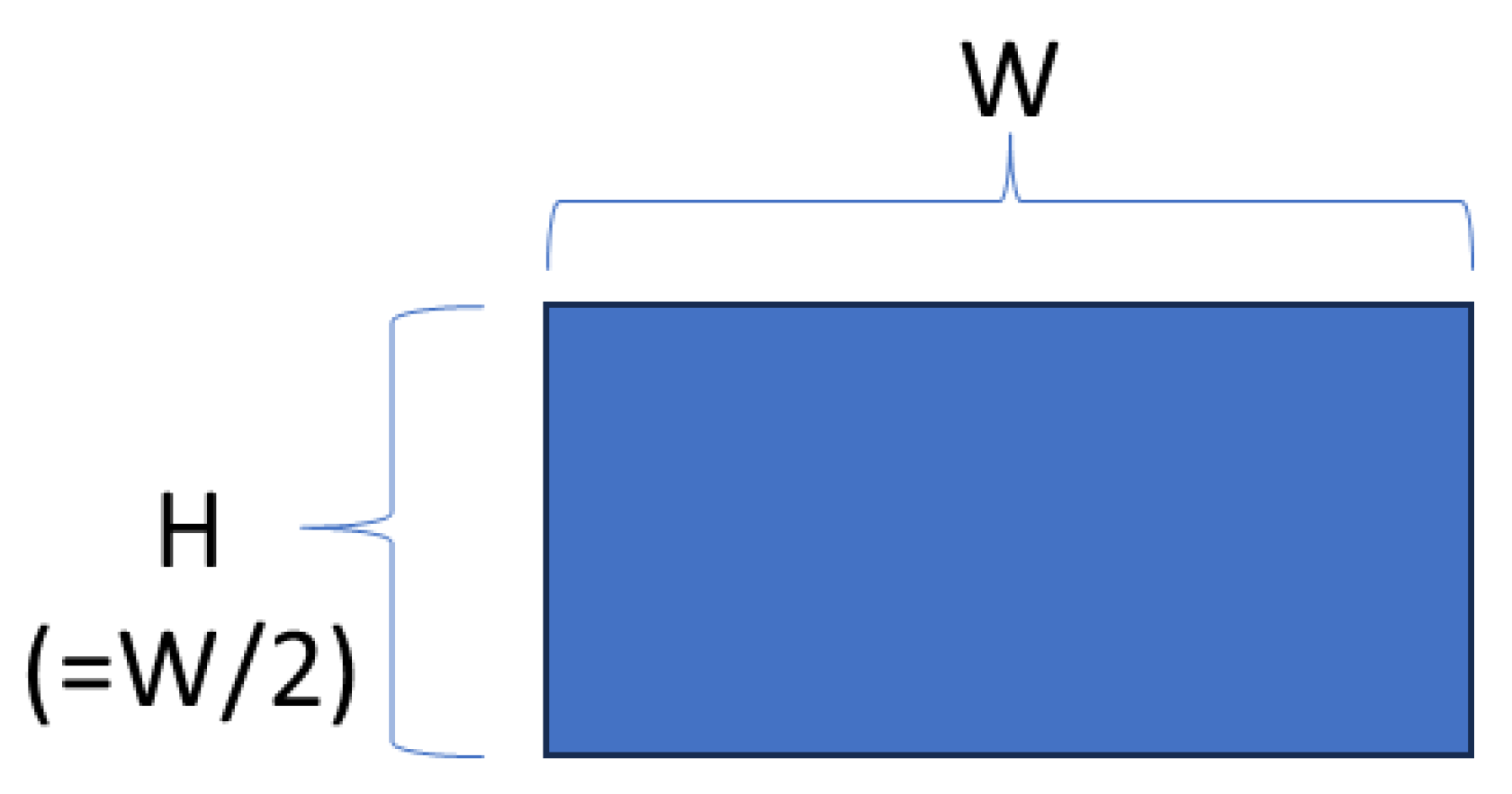
This application is modeled as a rectangular prism with a cross-sectional width, W, and height, H, extruded along an arbitrarily long length, L. Figure A1 illustrates a labeled cross-section of the generalized simple structure. In order to align the geometry with the standard extrusion cross-section typical of single-nozzle extrusion, the ratio between W and H is defined as 2:1. It should be noted, however, that using any multiple of W 2 would yield the same final results after normalization. For this geometry, the required features for printing the structure are that the system must print a solid block that exactly fills the dimensions of W and H. Due to the geometric constraints and the limitation on exceeding the print dimensions, the layer height must be a unit fraction of H equal to H n l , where n l is the number of layers needed to complete the print. Similarly, the nozzle diameter, d, must also be a unit fraction of the width W n p , where n p is the integer number of passes the nozzle must make per layer. Due to the conveniently selected geometric ratio of the rectangular prism, n l will always equal n p . Values between 1 and 10 are used as the inputs for both of these denominators in the following calculations, and equally sized teeth are considered for the SSE system.
Figure A1. Generalized geometry of the simple structure, as shown from a front view.
Jmmp 08 00145 g0a1

Appendix A.3.2. Material Used

Given the requirement to fill the rectangular prism along its entire length and the assumption that this task is possible for all nozzle diameters, the material usage is constant across all systems. The volume of material used is simply the volume of the desired rectangular prism, which is
V o l u m e = W H L = W 2 L 2 .

Appendix A.3.3. Material Extrusion Rate

Equation (A2) provides the relationship between the material flow rate with respect to the diameter of the nozzle. Since the geometric constraints require the use of nozzle diameters that are a unit fraction of the width of the rectangular prism, the flow rate of all relevant nozzles can be calculated by substituting the relevant fraction in place of the nozzle diameter in Equation (A2), yielding
Q single = v ( W / n p ) 2 2 = v ( W ) 2 2 n p 2 .
This calculation of extrusion rate for nozzle sizes ranging from W to W 10 provides a useful range to calculate the time required for single-nozzle systems of various sizes to print a generalized rectangular prism, as shown in Appendix A.3.5.
Equation (2) enables the calculation of the extrusion rate of the SSE system using tooth sizes matching the nozzle diameters being investigated and a total width equal to W. The width of each tooth ( w t ) must be W n t . After simplification, the SSE extrusion rate as a function of the number of teeth is
Q SSE = v W 2 2 n t .
Given the previously asserted assumption that the teeth must be of equal size, as the size of the teeth changes, the number of teeth ( n t ) needed to obtain the same resolution as a single-nozzle system will always align with the number of passes ( n p ) a single-nozzle system would take. By considering instances when these two values are equal, the performance of the SSE system can be compared with single-nozzle systems capable of achieving equivalent printing resolution.

Appendix A.3.4. Time Required to Print Structure

To calculate the time required to complete the generalized print (T), the volume of material used from Equation (A4) (which is a constant for this case) is divided by the extrusion rate of the single-nozzle systems (Equation (A5)) and the SSE systems (Equation (A6)). For the case of single-nozzle systems, this results in
T single = W 2 L 2 / v W 2 2 n p 2 = n p 2 L v ,
while the SSE calculation yields
T SSE = W 2 L 2 / v W 2 2 n t = n t L v .
For the single-nozzle equation that calculates the time required to print, the time to print increases quadratically with respect to the number of passes ( n p ) or the inverse of the nozzle size. In contrast, the SSE system shows only a linear relationship between the time required to print and the number of teeth or the inverse of the tooth size.

Appendix A.3.5. Table of Results

Due to the simple nature of the desired geometry, this section only compares the time required to print, as it is assumed that all systems use the same volume of material. As discussed in Appendix A.3.3, examples of nozzle diameters ranging from W to W / 10 are examined, as this provides a thorough overview of how the speed of printing changes with nozzle diameter (effectively resolution) while printing a solid object. Similarly, tooth widths matching the size of the nozzle diameters are used in order to compare the two technologies by comparing systems with matching resolutions. Equations (A7) and (A8) use W / n p and W / n t , respectively, to represent the nozzle diameter. Therefore, when calculating the values for the time taken in the table below, the effective nozzle size—calculated as the nozzle diameter with W assumed to be one—is used as a scalar to represent W / n p and W / n t , respectively, in Equations (A7) and (A8). As described in Appendix A.2, the resulting time taken is normalized to the most efficient single-nozzle solution, which, in this case, is the largest nozzle with a width of W capable of printing the generalized structure in a single pass, thus equating to L v with an effective nozzle width of 1. This allows the constants L and v to be dropped, as the relative performance of the systems is compared and the results are normalized as described in point 5, of Appendix A.2.
Table A1. Normalized print times of single-nozzle systems and SSE systems with various nozzle diameters and tooth widths while printing a simple rectangular prism.
Nozzle Diameter/Tooth WidthW W 2 W 3 W 4 W 5 W 6 W 7 W 8 W 9 W 10
Effective Nozzle Size ( n p and n t )1.000.500.330.250.200.170.140.130.110.10
Single-Nozzle Relative Time to Print149162536496481100
SSE System Relative Time to Print12345678910
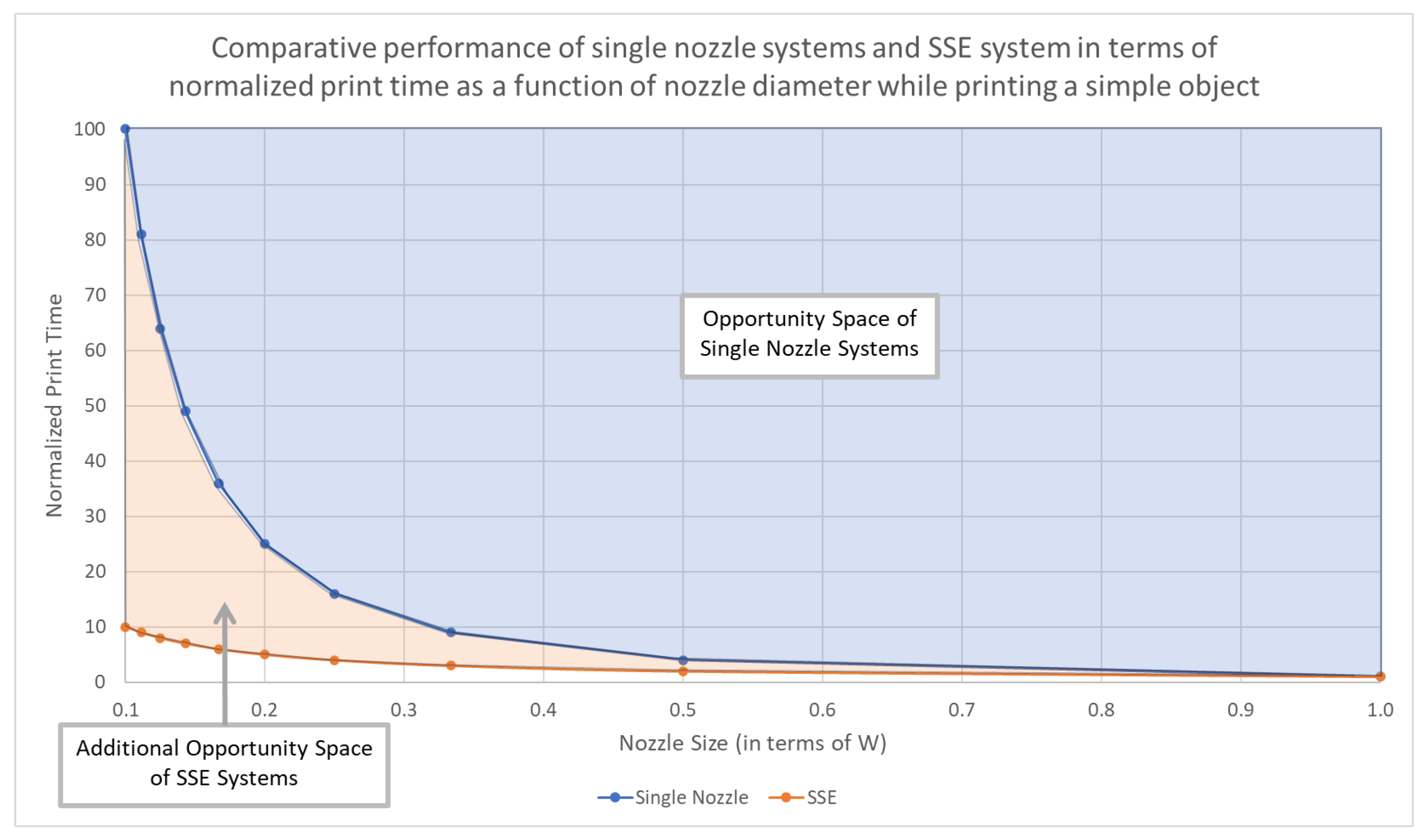
At the extreme size in which the SSE system has a single tooth with a width equal to W and the single-nozzle system has an equivalent diameter, they are effectively the same system, and thus both systems can complete the print in the same time. On the other hand, when resolution is emphasized, with both the nozzle diameter and the width of teeth reaching W 10 , the single-nozzle system takes 100 times as long to print, while the SSE system takes only 10 times as long to print compared to the largest-sized systems. This difference can be seen in Figure A2, which compares the normalized print time vs. nozzle size (equivalent to resolution) for both systems.
While enhanced resolution may not be needed for a simple structure, as described in this example, Figure A2 shows that the SSE system provides an opportunity space outside the boundaries of a single-nozzle system with respect to print time vs. resolution.
Figure A2. Plot of normalized print time vs. nozzle size (resolution) for printing a simple structure using either a single-nozzle system or the SSE system.
Jmmp 08 00145 g0a2

Appendix A.4. Application to a Generalized Wall Structure

This second example compares the performance of the single-nozzle and SSE systems in printing a generalized wall. The use of LFAM technologies, especially 3DCP (3D concrete printing), to print walls is a common topic of both research and commercial interest, with recent reviews of 3DCP highlighting that most systems do not attempt to print anything other than the walls of the structure [36]. As such, theoretical analysis of how the SSE system compares with traditional, single-nozzle systems in printing a wall provides an exigent comparison.

Appendix A.4.1. Generalized Geometry

This section presents a generalized representation of a wall geometry, specifically the middle portion of a straight wall. In its most basic form, a wall has three features: two surfaces and an interior. While wall structures can be formed using LFAM systems in many different ways, there are two basic methods at the highest level: the system can print the walls as a solid line, or the system can print the wall as two surface layers with an interior structure that provides lateral structure for the surface layers. It is posited that both of these walls could be generalized to the second form, with the first form being a special case of the second, in which all three elements are merged into a single solid layer. As such, the most general form of a wall consists of two surface layers and an interior structure to link the two surfaces.
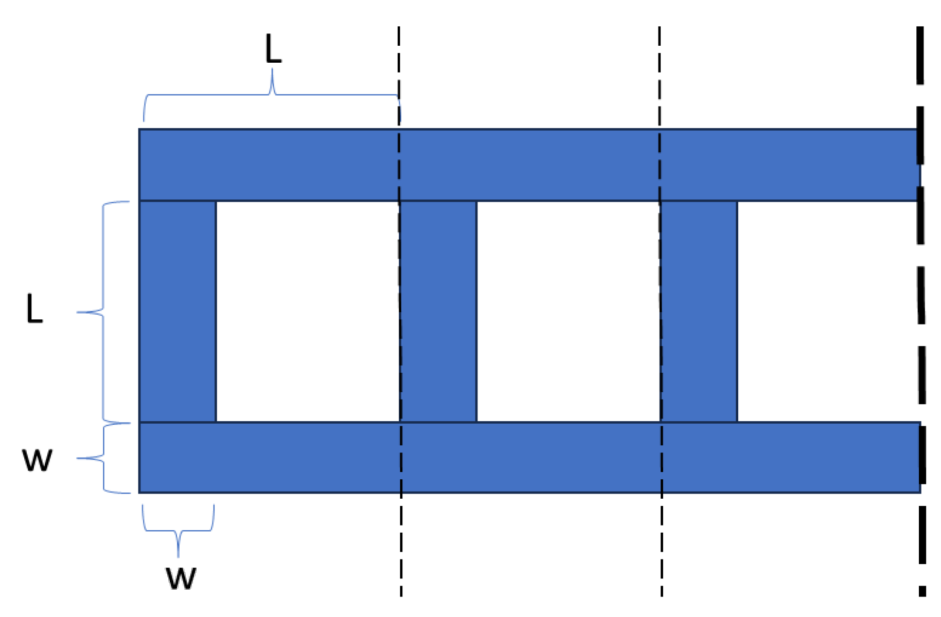
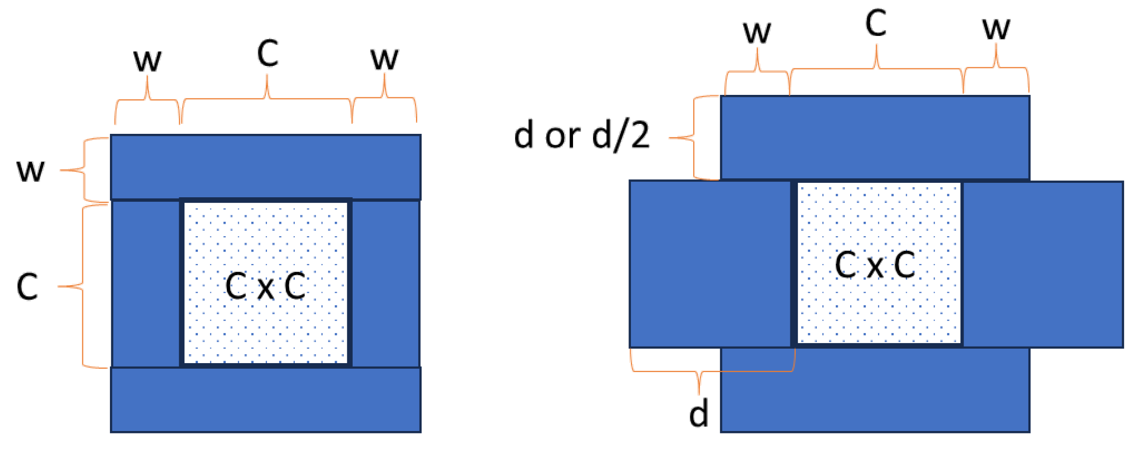
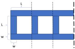
In consideration of this generalized description of a wall, the geometry proposed in Figure A3 shows a top view of three repeating units of a structural unit, which is referred to as a digital concrete masonry unit (DCMU), due to its similarity to the ubiquitous concrete masonry units (also called concrete blocks) used throughout the world in the construction of walls. In this case, the top and bottom lines running horizontally in this figure represent the two surface layers, and the repeating vertical elements represent the lateral structural supports that support these two surface layers. These lateral elements are usually printed as a zigzag when using single-nozzle systems, as this avoids the stops and starts associated with printing short lines between the two wall surfaces, as shown in Figure A3. Printing these short vertical lines with a single-nozzle system would likely slow the print and cause geometric defects associated with stopping and starting frequently. However, due to the assumptions in Appendix A.2, specifically that non-printing moves are ignored and the single-nozzle systems can follow a path to fill the geometry efficiently, the limitations of the single-nozzle systems can be disregarded, enabling the use of such a simplified geometry for comparison.
Figure A3. Generalized geometry of a wall structure showing the top view of three units of a repeating structural element.
Jmmp 08 00145 g0a3
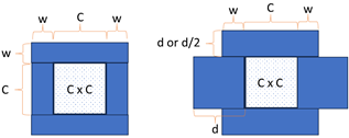
In this case, two other assumptions are made about the geometry of the figure: first, that the length of the repeating elements matches the length of the vertical supporting elements, and second, that the width of the elements making up the surfaces is the same as that of the supporting elements. While these simplifying symmetries are not strictly necessary, these assumptions yield reasonable geometries that a single-nozzle system could easily print while simultaneously enabling the development of a generalized structure that supports a meaningful comparison. Finally, for clarity of the geometric constraints, all of the defined areas must be printed without any surfaces being modified. However, the voids in the middle are optional, and thus are increasingly filled as nozzle diameters increase due to the reduction in resolution.
In order to normalize the data and obtain scalar results, the system must be reduced to contain only a single variable affecting the printing dynamics. Therefore, it is assumed that L is equivalent in length to 5 w , approximately matching the geometry of the drawing. Beyond this, the number of layers (height of the wall) and length of the entire wall (the number of repeating units) are constants that can be normalized and are left out of the explicit calculations in the following sections, with the calculations only considering the printing of a single repeating unit.

Appendix A.4.2. Material Used

In this example, any nozzles larger in diameter than w will create lines that exceed the dimensions of the given geometry, effectively reducing the size of the internal void. When the size of the nozzle reaches 2 w + L 2 or, equivalently, 7 w 2 in diameter, the voids are completely eliminated. Similarly, any nozzle sizes less than w in diameter will use the same amount of material as nozzles with a size of w. As such, material usage for single-nozzle systems with nozzle diameters outside this range is not affected up to the maximum width of the wall, which is 7 w .
It is useful to first calculate these minimum and maximum material usage scenarios. The optimal material usage scenario is that which matches the geometry exactly, as this is the minimum requirement of the defined geometry. Given the simplification that L = 5 w , the area of a single unit is calculated to be
w ( 3 L ) = w ( 3 5 w ) = 15 w 2 .
In order to calculate the maximum material usage for the wall structure, it is necessary to calculate the area with the central voids filled, as happens when using a nozzle diameter greater than 7 w 2 and less than 7 w . The resulting area to be printed is
L ( 2 w + L ) = 5 w ( 7 w ) = 35 w 2 .
In order to calculate the material used by nozzles of varying diameters to print a single unit of the wall in the range between the extremes described above, it is necessary to accurately calculate the extra material used. Since the nozzles have resolutions exceeding w, it is assumed that the width of the nozzle replaces w by displacing the interior lines of the structural unit and reducing the size of the internal void. If the nozzle diameter is defined as d, for nozzles between the sizes of w and 7 w 2 , the material used is
2 L d + d ( L 2 ( d w ) ) = d ( 10 w + 5 w 2 ( d w ) ) = d ( 17 w 2 d ) .
Equations (A9)–(A11) provide accurate measures of the area that is filled in each repeating unit by nozzles of various sizes, ranging from less than w to as much as 7 w . Since the SSE system is assumed to be optimized for the targeted geometry, it will have a tooth width, w t , of w across a nozzle width of 7 w and will print the DCMU pattern using the minimum amount of material, as described by Equation (A9). If a constant height, H, is assumed for the generalized wall structure, it is possible to obtain a volumetric measure of the material used to print the structure, which can be used in the next sections before normalizing out the height in the results table.

Appendix A.4.3. Material Extrusion Rate

The material extrusion rates for various nozzle sizes remain the same as those calculated in Equation (A2). An example of the simple calculation for the extrusion rate, Q, of a single-nozzle system with a diameter equal to w yields
Q single = v w 2 2 .
The extrusion rate for the SSE system changes with time, as the number of teeth that are open and allowing extrusion changes based on the internal structure of the print. In this case, the average extrusion rate can be used. Since the velocity is assumed to be constant, the relative length of each extrusion configuration can be used to determine the time spent in that configuration, which can be used to calculate a weighted average that yields the average extrusion rate while printing the structure with the SSE system. To ensure the clarity of this calculation, it can be seen that Equation (2) can be split such that w t and n t can be calculated as the printed width that varies with time. In the following calculation, the value L is intentionally not substituted out for the equivalent 5 w , to highlight the fact that the L dimension cancels out and does not directly affect the average extrusion rate of the SSE system for this geometry. As such, the average flow rate can be calculated as
Q SSE , avg . = v w 2 w ( L + 2 w ) + ( L w ) 2 w L = v w ( w L + 2 L w ) 2 L = 3 v w 2 2 .

Appendix A.4.4. Time Required to Print Structure

As in Appendix A.3.4, the time taken to complete a print is calculated by dividing the volume of material used by the extrusion rate for each system. For the case of single-nozzle systems with nozzle diameters between w and 7 w 2 , the time to print a single unit is calculated by taking the material needed and dividing by the flow rate.
T single = H d ( 17 w 2 d ) / ( v d 2 ) / 2 = H 34 w 4 d v d .
Outside of this nozzle diameter range, the material used is constrained by a minimum of 15 w 2 and a maximum of 35 w 2 in line with Equations (A9) and (A10), respectively. Beyond the defined diameter ranges, the minimum and maximum material usages should be used and divided by the calculated nozzle flow rate. With this modification, the equation is valid up to the maximum nozzle diameter of 7 w . Above that size, the system can no longer print the desired geometry, as it would violate the geometric constraints.
In the case of the SSE system, the time taken to print a single unit can be calculated in the same way as the single-nozzle systems
T SSE = H 15 w 2 / 3 v w 2 2 = 10 H v ,
showing that the time taken to print this geometry with the SSE system depends only on the wall’s height and the printer’s velocity. This result can be confirmed by realizing that the SSE system moves at a constant velocity and prints an entire width of the wall geometry with a height equal to w 2 in each pass. As such, the time taken can be calculated by considering the number of passes (layers) needed for a wall of a given height, and then multiplying by the time taken per pass on a single unit of length L = 5 w , yielding
T SSE = H w / 2 5 w v = 10 H v ,
which exactly matches the outcome of Equation (A15).

Appendix A.4.5. Table of Results

To generate the normalized table of results, a single-nozzle system with a nozzle diameter that can print the system with material efficiency at the fastest rate is used as the normalizing standard. For this case, the optimal diameter for material efficiency is a nozzle with a width of w. Thus, the table below presents both the material used and the time to print normalized to this system, to show the relative performance of each system across both dimensions.
Table A2. Normalized material usage and time to print a generalized wall example for single-nozzle systems with varying nozzle diameters and the optimal SSE system with a tooth width of w and nozzle width of 7 w .
Nozzle Diameter0.5w1w1.5w2w2.5w3w3.5w4w5w6w7w SSE
Material Usage (norm)1.001.001.401.732.002.202.332.332.332.332.33 1
Normalized Print Time4.001.000.620.430.320.240.190.150.090.060.05 0.33
The results from this table are visualized in the plot below, which shows the opportunity space of single-nozzle systems in printing this geometry, in which the technology performance is improved by moving towards the lower-left quadrant. The plot shows that the SSE system exceeds the opportunity frontier and includes dashed lines to show how the SSE system compares to single-nozzle systems with either the same material usage or print time.
Figure A4. Plot of normalized material usage vs. normalized print time while printing a generalized wall structure constructed of repeating DCMU elements. The performance of the optimal SSE configuration is included in orange. The dashed lines show how the optimal SSE performance intercepts with the opportunity space of single-nozzle systems.
Jmmp 08 00145 g0a4

Appendix A.5. Application to a Generalized Conduit Structure

While the first example looked at a very simple solid structure and the second application investigated the performance of the systems in the most common application of constructing walls in which the central voids are allowed to disappear, this third example looks at printing a conduit in which a central void must be maintained and is meant to represent a conduit that could stand alone or be integrated into another structure.

Appendix A.5.1. Generalized Geometry

The geometry of a conduit is generalized by first defining a square cross-section with sides of length C, which represents the central channel that must be maintained as a void. The walls around this channel are then defined as having a minimum width of w, as shown in Figure A5, which shows a front view of the desired geometry on the left side. Using the SSE system or single-nozzle systems with a resolution of w or less, this will be the geometry that is printed. However, as in the case of the wall structure covered in Appendix A.4, systems with larger nozzles use additional material to complete the task, as the actual wall thicknesses will exceed the minimum width requirement for the wall. Unlike the case with the wall structure where the fixed geometry is the wall’s exterior surface, the fixed geometry in this case is the interior channel of the conduit. As a result, the extra material spreads outwards when the nozzle diameter d exceeds the width of the walls w surrounding the void. Additionally, the height of the bottom and top portions of the conduit’s enclosure expand vertically when the layer height does not divide evenly into the minimum layer thickness w, as an additional layer must be deposited to meet the minimum thickness. This becomes particularly significant when the nozzle diameter is between w and 2 w , as two full layers must be deposited in order for the layer height to reach the minimum thickness, resulting in nearly twice the minimum layer thickness as the nozzle diameter approaches 2 w . In this case, the height of these elements becomes d when the layer thickness d 2 is less than the minimum thickness of w, as two layers must then be printed. On the other hand, when the nozzle is large enough such that d 2 is greater than w, only one layer must be printed to meet the required thickness. While the issue of matching the layer height with the geometry is present in all of the previous cases, and even in the side walls of this geometry, the effects are relatively minor in comparison with the more dramatic effect occurring at the top and bottom of the conduit with nozzle diameters between w and 2 w . As a result, while layer-height matching is generally not considered in this work, this specific range is considered for this geometry due to the relatively large effect that the additional layer has on print time and material use.
Figure A5. Generalized geometry of a conduit showing the front view of (left) the desired geometry and (right) an example of the expanded geometry that results when a nozzle with diameter, d, greater than w is used.
Jmmp 08 00145 g0a5
This cross-section representing a conduit is printed over an arbitrary length L, which does not affect the results due to normalization. The materials are all assumed to be capable of bridging the spans and/or overhangs that are created either across the top of the cavity or on the sides when larger nozzle diameters are used. Additionally, to reduce the free variables in the problem, it is assumed that the cavity width, C, is equal to three times the minimum width, w, of the walls enclosing the cavity, resulting in a total minimum width and height of 5 w .

Appendix A.5.2. Material Used

In cases of printing the desired geometry, the calculation of the volume of material needed is
4 L w ( w + C ) ,
and represents the material used by both the SSE systems and the single-nozzle systems with nozzle diameters, d, less than w, such that their resolution enables the systems to accurately print the desired geometry according to the assumptions made in Appendix A.2.
On the other hand, when calculating the geometry for nozzles with diameters, d, exceeding w, the volume needed becomes
2 L 2 d 2 ( 2 w + C ) + 2 L d C = 4 L d ( w + C ) ,
for nozzles with d 2 < w , and
2 L d 2 ( 2 w + C ) + 2 L d C = L d ( 2 w + 3 C ) ,
for nozzles with d 2 > w . The difference between these two cases where w d arises from the fact that the intermediately large nozzles must print two layers in the top and bottom sections of the geometry rather than one, which can result in more material being required in these top layers, despite the nozzle technically having a better resolution.

Appendix A.5.3. Material Extrusion Rate

For this geometry, the extrusion rates of the single-nozzle systems all follow the general rule described in Equation (A2). For the SSE system, it is necessary to use the same methodology as used in Appendix A.4.3, due to the two nozzle configurations that must be used to complete the print. In this case, changes in extrusion occur on an interlayer basis rather than intralayer basis, but the method still works, in that the time spent per layer is constant and thus it is possible to determine the average extrusion by weighting the two extrusion paradigms by the height of the sections that they are used for. In this case, the SSE system will spend 2 w 2 w + C of the time printing at full extrusion width, while spending the remaining portion ( C 2 w + C ) printing only the exterior walls of the hollow portion of the conduit. Using this weighting, the material extrusion rate for the SSE system with teeth with a width, w t , equal to w becomes
Q SSE , avg . = ( v w 2 ( 2 w ( 2 w + C ) + ( C 2 w ) ) ) / 2 w + C = 2 v w 2 w + C 2 w + C .

Appendix A.5.4. Time Required to Print Structure

As before, dividing the material used by the material extrusion rate yields the time required to print the defined conduit with length L. For single-nozzle systems, three separate calculations are required due to the different geometries that emerge as a result of the reduced resolution. For d w ,
T single , d w = 4 L w ( w + C ) / v d 2 2 = 8 L w ( w + C ) v d 2 ,
while for w d < 2 w ,
T single , w d < 2 w = 4 L d ( w + C ) / v d 2 2 = 8 L ( w + C ) v d ,
and for 2 w < d ,
T single , 2 w < d = L d ( 2 w + 3 C ) / v d 2 2 = 2 L ( 2 w + 3 C ) v d .
The time required to print with the SSE system is
T SSE = 4 L w ( w + C ) / 2 v w 2 w + C 2 w + C = 2 L ( 2 w + C ) v w .
In consideration of the assumption made in Appendix A.5.1 that the conduit width, C, is equal to three times the minimum wall width, w, the above equations can be presented again, with that assumption being used to simplify the result. First, for single-nozzle systems in which d w ,
T single , d w = 32 L w 2 v d 2 ,
while for w < d 2 w ,
T single , w d < 2 w = 32 L w v d ,
and for 2 w < d ,
T single , 2 w < d = 22 L w v d .
The time required to print with the SSE system is
T SSE = 10 L v ,
meaning that, for the optimal SSE system—with tooth width equal to w and nozzle width equal to 2 w + C —assuming a constant relationship between w and C results in a print time for the SSE system that is not a function of w or C while printing the generalized conduit geometry.

Appendix A.5.5. Table of Results

Appendix A.5.2 and Appendix A.5.4, respectively, provide equations to calculate the material use and time taken by single-nozzle systems of various diameters, as well as the SSE system. The simplified equations from Appendix A.5.4, which assume the ratio of C = 3 w , are used in this section. Additionally, the data are normalized with respect to the fastest nozzle capable of accurately printing the ideal (minimum material use) geometry, which occurs when d = w . To provide a clear picture of the opportunity space of single-nozzle systems, nozzle diameters ranging from half the width of the minimum wall width ( w 2 ) to twice the width of the hollow section of the conduit 2 C ( 6 w ) are used to determine material use and time to print.
Table A3. Normalized material usage and time to print a generalized conduit structure for single-nozzle systems of various diameters and the SSE system.
Nozzle Diameter0.5w1w1.33w1.66w1.9w2w3w4w5w6w SSE
Material Usage (norm)1.01.01.31.71.91.42.12.83.44.1 1.0
Normalized Print Time4.01.00.80.60.50.30.20.20.10.1 0.3
The table is plot in Figure A6, below, which focuses on the most relevant area of comparison between the theoretical performance of the single-nozzle systems and the SSE system. The plot shows that the theoretical performance of the SSE system exceeds the opportunity frontier of single-nozzle systems by maintaining efficient material use, while taking only 30% of the time taken by a single-nozzle system with the same resolution. It is interesting to note that the inflection in the line between 1.9w and 2w is caused by the need for two layers on the top and bottom of the conduit until d 2 w , resulting in significantly more material use as d approaches this critical point. As such, the opportunity space of single-nozzle systems extends beyond the plotted line capturing nozzle performance, as using a larger nozzle of resolution 2 w would reduce material usage (and print time) when compared with some slightly smaller nozzles.
Figure A6. Plot of normalized material usage vs. normalized print time while printing a generalized conduit structure. The performance of the optimal SSE configuration is included in orange with dashed lines showing the intercepts with the opportunity space of single-nozzle systems. The opportunity space actually exceeds the line plot due to the inefficiency of smaller nozzles when printing the conduit geometry, as discussed above.
Jmmp 08 00145 g0a6

References

  1. Prashar, G.; Vasudev, H.; Bhuddhi, D. Additive manufacturing: Expanding 3D printing horizon in industry 4.0. Int. J. Interact. Des. Manuf. 2022, 17, 2221–2235. [Google Scholar] [CrossRef]
  2. Whitehead, J.; Lipson, H. Multi-Process Printing Method Combining Powder and Resin Based Additive Manufacturing. Addit. Manuf. Lett. 2022, 3, 100062. [Google Scholar] [CrossRef]
  3. Roach, D.J.; Hamel, C.M.; Dunn, C.K.; Johnson, M.V.; Kuang, X.; Qi, H.J. The m4 3D printer: A multi-material multi-method additive manufacturing platform for future 3D printed structures. Addit. Manuf. 2019, 29, 100819. [Google Scholar] [CrossRef]
  4. Gibson, I.; Rosen, D.W.; Stucker, B. Additive Manufacturing Technologies: Rapid Prototyping to Direct Digital Manufacturing, 1st ed.; Springer: New York, NY, USA, 2010. [Google Scholar] [CrossRef]
  5. Roberts, T. Additive Manufacturing Trend Report 2021; Technical Report; HUBS: Amsterdam, The Netherlands, 2021. [Google Scholar]
  6. Schwaar, C. 3D-Printed Rockets Set to Blast Off. 2022. Available online: https://www.forbes.com/sites/carolynschwaar/2022/06/30/3d-printed-rockets-set-to-blast-off/?sh=5016bc0b2b6a (accessed on 6 June 2024).
  7. Hitchens, O. 3D-Printed Rocket Engines: The Technology Driving the Private Sector Space Race. 2021. Available online: https://www.space.com/3d-printed-rocket-engines-private-space-technology (accessed on 6 June 2024).
  8. Ngo, T.D.; Kashani, A.; Imbalzano, G.; Nguyen, K.T.; Hui, D. Additive manufacturing (3D printing): A review of materials, methods, applications and challenges. Compos. Part B Eng. 2018, 143, 172–196. [Google Scholar] [CrossRef]
  9. Love, L.; Post, B.; Noakes, M.; Nycz, A.; Kunc, V. There’s Plenty of Room at the Top. Addit. Manuf. 2020, 39, 101727. [Google Scholar] [CrossRef]
  10. Buswell, R.A.; de Silva, W.R.L.; Jones, S.Z.; Dirrenberger, J. 3D printing using concrete extrusion: A roadmap for research. Cem. Concr. Res. 2018, 112, 37–49. [Google Scholar] [CrossRef]
  11. Kishore, V.; Ajinjeru, C.; Nycz, A.; Post, B.; Lindahl, J.; Kunc, V.; Duty, C. Infrared preheating to improve interlayer strength of big area additive manufacturing (BAAM) components. Addit. Manuf. 2017, 14, 7–12. [Google Scholar] [CrossRef]
  12. Borish, M.; Post, B.K.; Roschli, A.; Chesser, P.C.; Love, L.J. Real-Time Defect Correction in Large-Scale Polymer Additive Manufacturing via Thermal Imaging and Laser Profilometer. Procedia Manuf. 2020, 48, 625–633. [Google Scholar] [CrossRef]
  13. Roschli, A.; Gaul, K.T.; Boulger, A.M.; Post, B.K.; Chesser, P.C.; Love, L.J.; Blue, F.; Borish, M. Designing for Big Area Additive Manufacturing. Addit. Manuf. 2019, 25, 275–285. [Google Scholar] [CrossRef]
  14. Chesser, P.; Post, B.; Roschli, A.; Carnal, C.; Lind, R.; Borish, M.; Love, L. Extrusion control for high quality printing on Big Area Additive Manufacturing (BAAM) systems. Addit. Manuf. 2019, 28, 445–455. [Google Scholar] [CrossRef]
  15. Hirsch, P.; Scholz, S.; Borowitza, B.; Vyhnal, M.; Schlimper, R.; Zscheyge, M.; Kotera, O.; Stipkova, M.; Scholz, S. Processing and Analysis of Hybrid Fiber-Reinforced Polyamide Composite Structures Made by Fused Granular Fabrication and Automated Tape Laying. J. Manuf. Mater. Process. 2024, 8, 25. [Google Scholar] [CrossRef]
  16. Butt, J.; Bhaskar, R.; Mohaghegh, V. Investigating the Influence of Material Extrusion Rates and Line Widths on FFF-Printed Graphene-Enhanced PLA. J. Manuf. Mater. Process. 2022, 6, 57. [Google Scholar] [CrossRef]
  17. Lu, B.; Weng, Y.; Li, M.; Qian, Y.; Leong, K.F.; Tan, M.J.; Qian, S. A systematical review of 3D printable cementitious materials. Constr. Build. Mater. 2019, 207, 477–490. [Google Scholar] [CrossRef]
  18. Goh, G.D.; Wong, K.K.; Tan, N.; Seet, H.L.; Nai, M.L.S. Large-format additive manufacturing of polymers: A review of fabrication processes, materials, and design. Virtual Phys. Prototyp. 2024, 19, e2336160. [Google Scholar] [CrossRef]
  19. Singh, A.P.; Pervaiz, S. Current Status and Prospects of Multi-Jet Fusion (MJF) Based 3D Printing Technology. In Proceedings of the ASME 2021 International Mechanical Engineering Congress and Exposition, Online, 1–5 November 2021. [Google Scholar]
  20. Shakor, P.; Chu, S.H.; Puzatova, A.; Dini, E. Review of binder jetting 3D printing in the construction industry. Prog. Addit. Manuf. 2022, 7, 643–669. [Google Scholar] [CrossRef]
  21. Chen, H.; Zhang, D.; Chen, P.; Li, N.; Perrot, A. A Review of the Extruder System Design for Large-Scale Extrusion-Based 3D Concrete Printing. Materials 2023, 16, 2661. [Google Scholar] [CrossRef] [PubMed]
  22. Tagscherer, N.; Bär, A.M.; Zaremba, S.; Drechsler, K. Mechanical Analysis of Parameter Variations in Large-Scale Extrusion Additive Manufacturing of Thermoplastic Composites. J. Manuf. Mater. Process. 2022, 6, 36. [Google Scholar] [CrossRef]
  23. Vidakis, N.; Petousis, M.; David, C.N.; Sagris, D.; Mountakis, N.; Karapidakis, E. Mechanical Performance over Energy Expenditure in MEX 3D Printing of Polycarbonate: A Multiparametric Optimization with the Aid of Robust Experimental Design. J. Manuf. Mater. Process. 2023, 7, 38. [Google Scholar] [CrossRef]
  24. Yuan, P.F.; Zhan, Q.; Wu, H.; Beh, H.S.; Zhang, L. Real-time toolpath planning and extrusion control (RTPEC) method for variable-width 3D concrete printing. J. Build. Eng. 2022, 46, 103716. [Google Scholar] [CrossRef]
  25. Abilgaziyev, A.; Kulzhan, T.; Raissov, N.; Ali, M.H.; Match, W.L.; Mir-Nasiri, N. Design and development of multi-nozzle extrusion system for 3D printer. In Proceedings of the 2015 4th International Conference on Informatics, Electronics and Vision (ICIEV 2015), Fukuoka, Japan, 15–18 June 2015; Institute of Electrical and Electronics Engineers Inc.: New York, NY, USA, 2015; pp. 1–5. [Google Scholar] [CrossRef]
  26. Mhatre, P.S. Process Planning for Concurrent Multi-Nozzle 3D Printing. Master’s Thesis, Rochester Institute of Technology, Rochester, NY, USA, 2019. [Google Scholar]
  27. Panda, B.; Paul, S.C.; Tan, M.J. Anisotropic mechanical performance of 3D printed fiber reinforced sustainable construction material. Mater. Lett. 2017, 209, 146–149. [Google Scholar] [CrossRef]
  28. Khoshnevis, B.; Dutton, R. Innovative Rapid Prototyping Process Makes Large Sized, Smooth Surfaced Complex Shapes in a Wide Variety of Materials. Mater. Technol. 1998, 13, 53–56. [Google Scholar] [CrossRef]
  29. Lao, W.; Li, M.; Tjahjowidodo, T. Variable-geometry nozzle for surface quality enhancement in 3D concrete printing. Addit. Manuf. 2021, 37, 101638. [Google Scholar] [CrossRef]
  30. COBOD. BOD2 Specifications; Technical Report; COBOD: København, Denmark, 2020. [Google Scholar]
  31. Soltan, D.G.; Li, V.C. A self-reinforced cementitious composite for building-scale 3D printing. Cem. Concr. Compos. 2018, 90, 1–13. [Google Scholar] [CrossRef]
  32. Parrott, B. Fast Layered Extrusion for Additive Manufacturing. U.S. Patent Application 20230031850A1, 2 February 2023. Available online: https://patents.google.com/patent/US20230031850A1/ (accessed on 6 June 2024).
  33. Parrott, B. Fast Layered Extrusion for Additive Manufacturing. U.S. Patent Application US20230031400A1, 2 February 2023. Available online: https://patents.google.com/patent/US20230031400A1/ (accessed on 6 June 2024).
  34. Parrott, B. Fast Layered Extrusion for Additive Manufacturing. U.S. Patent Application 20230030198A1, 2 February 2023. Available online: https://patents.google.com/patent/US20230030198A1/ (accessed on 6 June 2024).
  35. Spitaels, L.; Fuentes, E.N.; Rivière-Lorphèvre, E.; Arrazola, P.J.; Ducobu, F. A Systematic Method for Assessing the Machine Performance of Material Extrusion Printers. J. Manuf. Mater. Process. 2024, 8, 36. [Google Scholar] [CrossRef]
  36. Bici, A.; Yunitsyna, A. Analysis of 3D printing techniques for building construction: A review. Constr. Robot. 2023, 7, 107–123. [Google Scholar] [CrossRef]
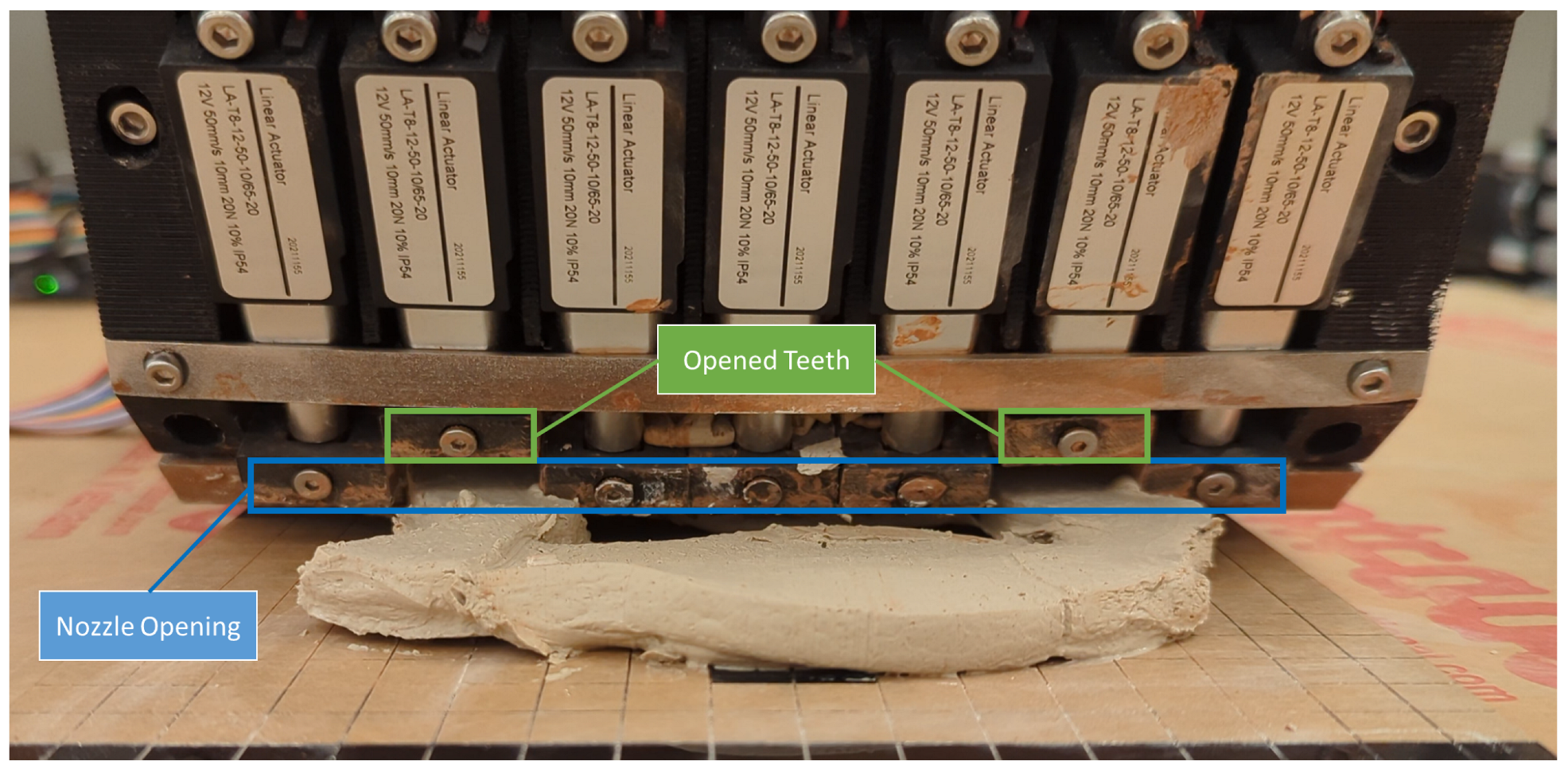
Figure 1. An image of a prototype SSE nozzle with seven actuators and teeth controlling flow through the nozzle opening. Clay has been extruded across a five-tooth width followed by the closure of the central three teeth, resulting in the extrusion of two separated walls and an internal cavity.
Jmmp 08 00145 g001
Figure 2. Plot of normalized material usage vs. normalized print time while printing a generalized wall structure constructed of repeating DCMU elements. The performance of the optimal SSE configuration is included in orange. The dashed lines show how the optimal SSE performance intercepts with the opportunity space of single-nozzle systems.
Jmmp 08 00145 g002
Figure 3. The selective sheet extrusion (SSE) prototype. Top: The SSE prototype mounted on the gantry system. (Bottom-left): Front view of the prototype print head (unmounted) shows the plunger mechanism raised to its upper height, as well as the opening of the nozzle at the very bottom with all teeth in the open position. (Bottom-right): The material cavity.
Jmmp 08 00145 g003
Figure 4. Matrix 3D Printer (M600) from Eazao. Unlike the direct extrusion used in the SSE system, this printer utilizes a tube to move the material from the material cartridge on the left to the print head, which uses an actuated screw drive to accomplish fine-tuned extrusion.
Jmmp 08 00145 g004
Figure 5. A labeled drawing of the tunnel model. Dimensions of all features are included in mm. The same model was used as the basis for the manually developed GCode used for the SSE prototype.
Jmmp 08 00145 g005
Figure 6. The smaller version of the tunnel geometry with the paths planned by Cura are shown.
Jmmp 08 00145 g006
Figure 7. The completed full-scale model printed by the single-nozzle printer (M600) is shown from three viewpoints. Left: front view. Center: isometric view. Right: side view. The only major defect resulted from poor performance in spanning the 22 mm gap at the top of the tunnel. (5 × 5 mm grid).
Jmmp 08 00145 g007
Figure 8. The completed smaller, scaled model printed by the single-nozzle printer (M600) is shown from three viewpoints. Left: front view. Center: top view. Right: side view. (5 × 5 mm grid).
Jmmp 08 00145 g008
Figure 9. The model printed by the prototype SSE system is shown from three viewpoints. Left: front view. Center: top view. Right: side view. The front edge of each layer printed inconsistently, and other geometric defects caused by imperfectly balanced flows or bubbles are observable. The clay color was changed after the first two layers for purely aesthetic reasons. (10 × 10 mm grid).
Jmmp 08 00145 g009
Table 1. Relative speed of SSE system by geometry.
DescriptionFigureTooth Count 1Fill FactorRelative Speed of SSE 2
Simple BoxJmmp 08 00145 i0011100%1 3
DCMUJmmp 08 00145 i002743%3
ConduitJmmp 08 00145 i003564%3.2
1 Optimal tooth count to achieve material efficiency and maximum speed. 2 Relative speed of an SSE system when compared with a single-nozzle system with the same resolution. 3 No speed increase is realized, as the optimal SSE system uses only one tooth, making it a single-nozzle system.
Disclaimer/Publisher’s Note: The statements, opinions and data contained in all publications are solely those of the individual author(s) and contributor(s) and not of MDPI and/or the editor(s). MDPI and/or the editor(s) disclaim responsibility for any injury to people or property resulting from any ideas, methods, instructions or products referred to in the content.