Abstract
This work discusses challenges in conventional grinding wheels: heat-induced tool wear and workpiece thermal damage. While textured abrasive wheels improve heat dissipation, the current surface-only methods, such as those based on laser and machining, have high renewal costs. The proposed manufacturing technology introduces an innovative 3D cooling channel structure throughout the wheel, enabling various channel geometries for specific abrasive wheel applications. The production steps were designed to accommodate the conventional pressing and sintering phases. During pressing, a 3D organic structure was included in the green body. A drying cycle eliminated all present fluids, and a sintering one burnt away the structure, revealing channels in the final product. Key parameters, such as binder type/content and heating rate, were optimized for reproducibility and scalability. Wear tests showed a huge efficiency increase (>100%) in performance and durability compared of this system to conventional wheels. Hexagonal channel structures decreased the wear rates by 64%, displaying superior wear resistance. Comprehensive CFD simulations evaluated the coolant flow through the cooling channels. This new design methodology for three-dimensionally structured grinding wheels innovates the operation configuration by delivering the coolant directly where it is needed. It allows for increasing the overall efficiency by optimizing cooling, reducing tool wear, and enhancing manufacturing precision. This 3D channel structure eliminates the need for reconditioning, thus lowering the operation costs.
1. Introduction
Precision manufacturing often utilizes grinding as a primary technique to fabricate components with meticulous accuracy, exceptional surface finish, and optimized dimensional tolerance [1,2,3]. Throughout the grinding process, the properties of the grinding wheel exert a substantial impact on the grinding force, temperature, and resultant surface quality of the workpiece [3,4]. Furthermore, ensuring the supply of cutting fluids during grinding operations becomes imperative to preserve surface integrity and mitigate tool wear [5]. Consequently, considerable emphasis is placed by academic and industrial sectors alike on advancing research and development related to grinding wheel technology [1,2,3,4,5].
The conventional geometry of grinding wheels hinders the dissipation of heat generated during the grinding process, while approximately 60% of the applied coolant fluids are not effectively utilized in the process, failing to reach the working surface [6,7,8]. The limited heat dissipation at the contact point can lead to excessive tool wear, increased grinding forces, residual stress, phase transformation, re-hardening, reduced material removal rate, surface defects, and other thermal damages [2,9,10,11]. Residual tensile stress and re-hardening burn pose significant challenges, as they adversely impact the longevity and dependability of a workpiece when exposed to fatigue conditions [12]. The thermal loads produced during the grinding process serve as the main contributor to these tensile residual stresses. The most effective approach to prevent the occurrence of such stresses is by maintaining the grinding temperatures below the tempering temperature of the workpiece [13,14]. Thus, within the specific tool-to-workpiece contact zone, the continual improvement of the local concentration and dispersion of the coolant/lubricant fluid is imperative for optimal performance [7,15]. On the other hand, the adoption of a Minimum Quantity Lubrication (MQL) is gaining attention, given the prevalent use of significant quantities of coolant lubricants in the metallurgical industry [16]. This widespread usage leads to elevated consumption and disposal expenses, also contributing to major environmental concerns [17].
Mineral oils, additives, and biocides improve the fluid performance in grinding while also increasing the number of toxic and deteriorating compounds in the global biosphere [18]. As a result, not only does the disposal of the fluid into the sewage system or into the waterways reduce the amount of drinking water available on the planet, but also it contaminates people and animals that come into contact with or ingest the water contaminated with the cutting fluid, having a direct impact on human health and the aquatic biosphere [19,20]. As a result, decreasing the use of conventional fluids is an urgent requirement for society to conserve the ecosystem [20].
To address these issues and optimize the operation, textured abrasive tools have been proposed [21]. By introducing grooves into a grinding wheel, it was possible to achieve a 61% reduction in energy consumption and double the material removal rate compared to what achieved with a non-textured tool [22,23,24]. Regarding the ability to enhance heat dissipation by incorporating microgrooves in grinding wheels, a temperature reduction of 105 °C and a 60% decrease in lubricant fluid consumption were observed during the grinding of aluminum [8,25]. The grooves in abrasive wheels serve as pockets, strategically designed to concentrate the jet towards the contact zone while effectively containing the fluid within [5]. This design feature not only enhances the flow rate within the contact zone but also facilitates the uniform flow of fluid and expels debris along the shortest path [5,26]. Consequently, it minimizes pore clogging and diminishes the abrasion of grinding debris, resulting in an even material removal and improved surface quality of the workpiece [26]. Additionally, textures on the grinding wheel assist in breaking up the air barrier that forms around the revolving wheel [27,28] and makes it difficult to properly supply the grinding fluid to the grinding zone [29]. As a result, adopting structured grinding wheels improves the efficiency of grinding processes [30].
At present, various processing techniques are employed for the production of textured grinding wheels [21]. It is evident that the machining process stands out as the most conventional and straightforward method for texturing grinding wheels [31,32,33]. Nevertheless, this is a manual process wherein the surface finish of the workpiece is typically not tightly controlled. Furthermore, mechanical texturing methods lead to substantial wear of the texturing tool and considerable vibration during grinding operations [8]. Alternative approaches, such as laser texturing [34,35,36,37], provide efficient and precise methodologies; however, they are associated with high costs and necessitate meticulous adjustment of process parameters [38]. Nearly all employed techniques thus far generate only surface-level grooves, necessitating a subsequent operation for retexturing after the grinding wheel undergoes wear. While Selective Laser Sintering (SLS) [39] offers the capability to produce internal channels, it is an expensive process and lacks feasibility for large-scale industrial production [40,41].
The conventional method of producing vitrified-matrix abrasive composites always involves the following processing steps: (i) powder mixing; (ii) powder pressing to form a green composite; (iii) drying the green composite; (iv) sintering the green composite. The powder mixing step involves abrasive grains (e.g., alumina), vitrified powder (the precursor of the vitrified matrix), and a temporary organic binder [42,43]. After mixing, the resulting powders are weighed and placed in a mold to be pressed and compacted into a specific geometry [44]. The mechanical consistency of the pressed green compact, resulting from this step, is ensured by the presence of an organic binder. The subsequent drying step aims to gently remove the water content associated with the temporary organic binder in the composite to prevent crack formation [45,46]. This is followed by the sintering step, which occurs in two phases. First, the organic components typically associated with the temporary binder burn off. Then, the vitrified powder softens, giving rise to the vitrified matrix of the abrasive composite upon cooling [47].
This article introduces an innovative methodology for manufacturing abrasive grinding wheels with a vitrified matrix, featuring a three-dimensional (3D) internal cooling structure system. Unlike conventional methods, this approach enables the production of wheels with permanent internal channels, eliminating the need for repeated operations after wear. Furthermore, it distinguishes itself from more advanced methods, like SLS, due to its practicality in manufacturing and minimal deviation from conventional processes. Additionally, this technology offers versatility in producing structured grinding wheels with various geometries, achieved through additive manufacturing (AM) to obtain a preform. Wear tests were conducted to evaluate the performance of these wheels, supplemented by comprehensive Computational Fluid Dynamics (CFD) simulations to better understand the effect of the coolant flow through the channels and its surface distribution. This multi-faceted approach provided valuable insights into the performance and durability of the structured grinding wheels, facilitating the interpretation and justification of the experimental results obtained from the wear tests.
This innovative approach aligns with the Industry 4.0 principles by leveraging advanced manufacturing techniques, such as AM, to enhance product functionality and performance. By integrating structures to form internal channels within abrasive composites, this method not only improves heat dissipation and reduces tool wear but also enables a precise control over the manufacturing process, ensuring higher quality and consistency. Furthermore, the adoption of such cutting-edge technology facilitates greater flexibility and customization in production, allowing for efficient adaptation to varying industrial demands and complex geometries. Ultimately, this advancement contributes to the creation of intelligent, efficient, and highly optimized manufacturing environments, embodying the core tenets of Industry 4.0.
2. New Grinding Wheel Design Methodology Concept
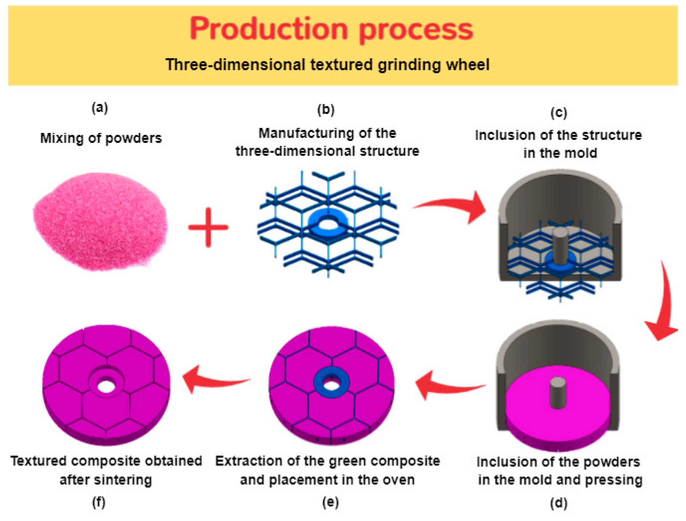
The concept behind this new methodology, illustrated in Figure 1, involves an abrasive wheel with a 3D internal cooling channel structure. This design offers versatility, accommodating various internal channel geometries suitable for different materials and grinding operations. Compared to traditional surface texturing methods for grinding wheels, this approach eliminates the need for reconditioning or renewing the wheel surface through machining or laser methods. This not only reduces the processing costs but also lowers the operational costs, including time, machine usage, and labor, for reconditioning.
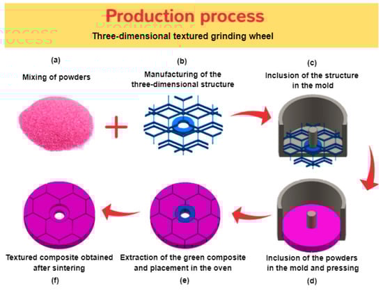
Figure 1.
Manufacturing process of grinding wheels with a 3D internal cooling structure system.
For processing these three-dimensionally structured wheels, during the pressing step (Figure 1d), a polymeric 3D preform (Figure 1b) that can be produced using methods such as AM [48] was introduced into the composite to form the desired channel structure geometry. The composite composition and pressing conditions were adjusted to prevent defects during this step, primarily due to the elastic recovery of the polymeric 3D structure. The polymeric structure remained within the green composite after pressing (Figure 1e) and was subsequently removed by combustion during the sintering cycle, creating a hollow internal network of channels with the desired geometry (Figure 1f). This innovative design offers flexibility in channel dimensions and geometry within the abrasive wheel.
The polymeric structure and the green abrasive composite have distinct properties, including mechanical behavior and coefficients of thermal expansion (CTE). These material differences affect their behavior differently with temperature changes. During pressing, the plasticity of the powder mixture significantly influences the inclusion and retention of the polymeric structure in the green composite. Consideration of these property divergences is crucial during the drying phase to prevent crack formation.
This new concept of abrasive wheels with internal cooling channels revolutionizes the grinding operations by directing the coolant fluid precisely where needed. The volume, pressure, and distribution of the coolant fluid are controlled by the 3D internal channel geometry.
This study focused on examining the innovative manufacturing methodology by studying the parameters influencing the inclusion of the 3D channel structure in the abrasive composite. This methodological advancement allows for the production of abrasive composites with a cooling channel structure throughout their volume, resulting in structured grinding wheels with self-regeneration capability. Consequently, improved workpiece surface quality is expected, alongside increased productivity and reduced processing costs due to the permanent presence of the channels.
3. Concept Development: Optimization of the Processing Conditions
In the context of developing this new methodology concept, some components and initial production process parameters were selected to be optimized. Several steps of the production process were studied to allow for the inclusion of the internal channel structure without physical and/or geometric defect formation. The manufacturing process of the grinding wheel with a 3D channel structure, initiated with the powder mixing stage (Figure 1a). The primary components of the vitrified abrasive composites developed for this study included alumina abrasive grains (with a particle size of 220 mesh) and a matrix precursor, such as a vitrified powder. Furthermore, a temporary organic binder, comprising a polysaccharide powder and water, was used to enable the green mechanical strength of the produced grinding wheels.
Simultaneously, a 3D channel structure precursor was created through additive manufacturing using a polymeric material (Figure 1b). The selection of the channel structure geometry was based on the CFD simulation results regarding the coolant distribution on the working surface. Also, for this work, a Polylactic Acid (PLA) filament of the doWire brand was used, along with an Ultimaker 3 printer for structure printing by Fused Deposition Modelling (FDM). Among other organic materials, PLA was chosen for its biodegradability, cost-effectiveness, and desired thermal characteristics. For example, during sintering, PLA could be combusted at temperatures lower than the melting point of the vitrified matrix precursor powders (620 °C). Additionally, PLA exhibits adequate mechanical properties for the intended application, ensuring the structural geometry is maintained. The printing conditions remained consistent throughout the process, maintaining a temperature of 220 °C, a print head speed of 40 mm/s, and a layer height of 0.1 mm per pass. In the subsequent phase, the channel structure was positioned in the mold, followed by the inclusion of the powder mixture on top and composite pressing at 27.5 MPa, as shown in Figure 1c,d respectively. Following this, the green composite was removed from the mold and placed in the oven for the thermal drying and sintering cycle, as depicted in Figure 1e. Finally, the three-dimensionally structured abrasive composite was obtained, as illustrated in Figure 1f.
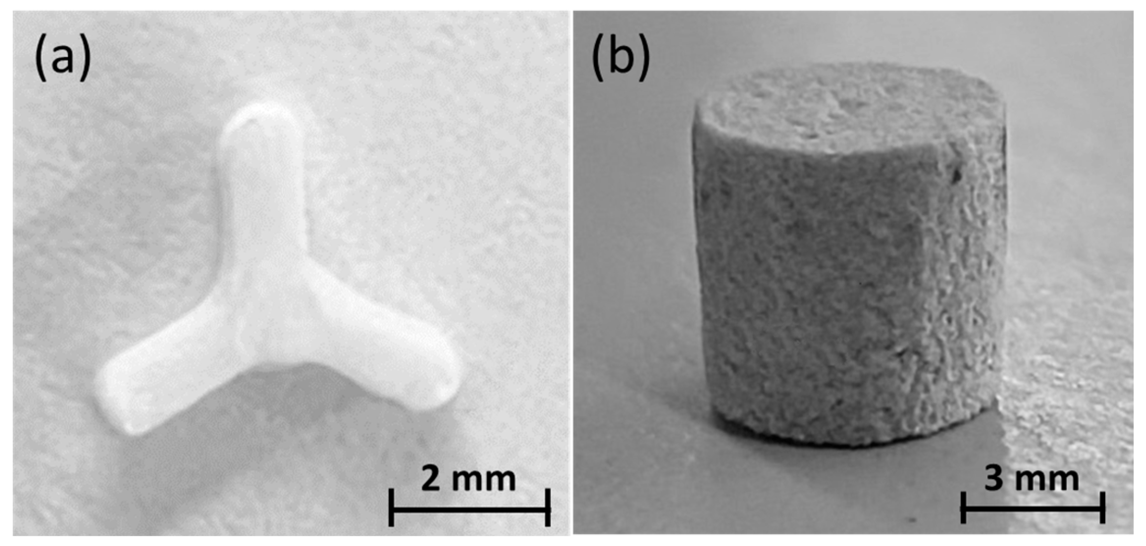
To examine the dimensional changes in abrasive composites caused by PLA incorporation, abrasive composite samples (∅6 × 6 mm) were produced, with and without a PLA channel structure. To this end, a Y-shaped PLA structure, shown in Figure 2, with an arm section measuring 1 × 1 mm and a length of 2 mm, was introduced before the pressing phase into the abrasive composite. Dimensional analyses were carried out on both specimen types, using the TMA Q400 equipment from TA Instruments [49]. The tests were carried out in air atmosphere, ranging from 30 up to 950 °C, with a preload of 0.01 N and a heating rate of 4 °C/min. Three samples were tested for each studied condition, and dimensional changes upon cooling were also recorded. Figure 3a compares the dimensional variation curves of the same abrasive composite, with and without the PLA structure included, in order to evaluate the impact of PLA on the composite deformation. To better understand the behavior of each raw material as a component present in the abrasive composite, Differential Scanning Calorimetry (DSC) assessments and Thermogravimetric Analysis (TGA) were performed on the PLA material (Figure 3b) and the polysaccharide solution—polysaccharide powder + water (Figure 3c). These analyses were conducted in air atmosphere at a heating rate of 10 °C/min, using the SDT2960 Simultaneous DSC-TGA equipment from TA Instruments.
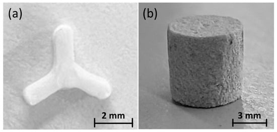
Figure 2.
(a) Y-shaped PLA structure employed in the production of ∅6 × 6 mm structured abrasive composite specimens for dimensional analyses (TMAs). (b) Abrasive composite sample (∅6 × 6 mm) with the Y-shaped PLA structure included.

Figure 3.
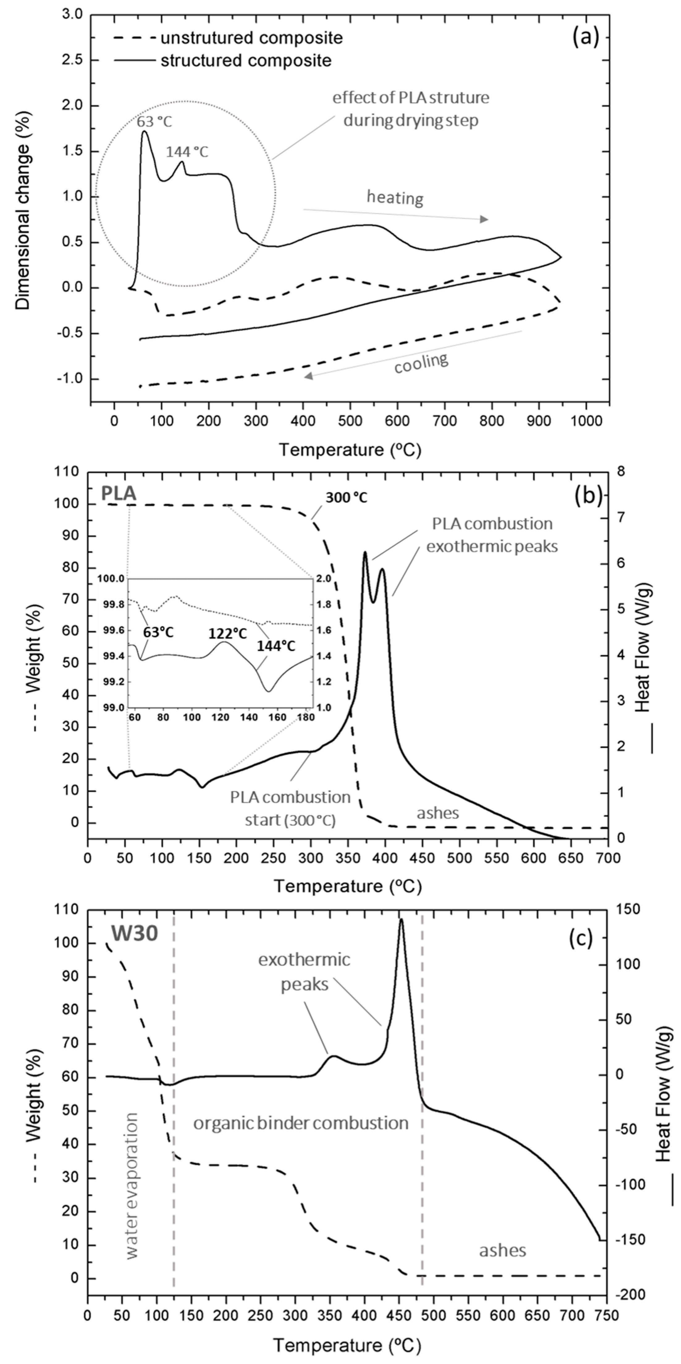
(a) TMA analysis of green composite samples with and without the incorporated PLA structure (4 °C/min, air atmosphere). (b) DSC/TGA analysis of the polysaccharide solution (10 °C/min, air atmosphere). (c) DSC/TGA analysis of the PLA channel precursor (10 °C/min, air atmosphere).
Comparing the linear dimensional variation curves of the abrasive composite samples with and without the PLA structure (Figure 3a), we observed different behaviors. It was evident that the most critical temperature range for processing the composite with the included PLA structure was between 30 °C and 300 °C. During the drying step, up to 80 °C, an expansion peak occurred at 63 °C, and the presence of PLA significantly increases the expansion/deformation of the composite. Another peak, which also seemed to be characteristic of the presence of the PLA structure in the abrasive composite, was observed before its sintering, at 144 °C. These two expansion peaks at 63 °C and 144 °C, only observable in the composite with the PLA structure, were linked to its transformations, such as glass transition (Tg) and melting point (Tm), respectively [50,51], and can be identified in the PLA DSC curve (Figure 3b). The crystallization temperature (Tc), at 122 °C [52,53], did not seem to significantly affect the abrasive composite dimensions. The DSC/TGA analyses revealed that the combustion of PLA initiated at 300 °C (Figure 3b) and occurred in two stages associated with two exothermic reactions (two peaks). It was accompanied by a mass reduction that concluded at 450 °C, at which point an almost complete mass reduction was observed. No significant residues from the 3D structure combustion were detected after the composite sintering. The significant expansion observed in the composite sample with the inclusion of PLA could lead to crack defects, which makes it an important parameter to control.
Except for the contribution of PLA (between 30 °C and 300 °C, when combustion began), both abrasive composites showed similar curve shapes up to 950 °C, at the end of the test. The curves showed identical oscillations, with a singular shift attributed to the initial impact of PLA on the dimensional variations of the composite during drying (Figure 3b). Between 30 °C and 100 °C, a shrinkage of the composite without the PLA structure was observed, corresponding to the evaporation of water from the polysaccharide solution. Between 275 °C and 475 °C, the organic binder combustion occurred in two steps, beginning at 275 °C and 425 °C, as depicted in Figure 3c. These two reactions were associated with a dimensional reduction for both abrasive composites (Figure 3a). The technical data sheet of the vitrified binder, used for this abrasive production, indicates that this material softens at 620 °C. It suggests that, during the sintering process of the abrasive composite, both PLA and the polysaccharide organic binder undergo combustion at lower temperatures (450 °C and 475 °C) compared to the softening temperature of the vitrified binder (620 °C). This effectively prevented the entrapment, within the vitrified matrix, of the ashes, formed from the combustion of these organic materials.
As shown in Figure 3a, the inclusion of the PLA 3D structure produced a significant change in the overall expansion behavior during the pressing and the initial part of the drying and sintering steps. The production of components without microstructural defects was carried out by combining the capacity for dimensional variation, through the variation of internal porosity, and by controlling the plasticity of the binding element in the composite structure during the pressing and thermal cycle stages.
The organic binder enhanced the plasticity of the composite, facilitating the proper accommodation of the mixture powders with the PLA structure. The presence of a polysaccharide solution (polysaccharide + water), as an organic binder, played an important role during the pressing stage in the sliding of the alumina grains, the compaction of the powders, and the incorporation of the PLA structure. To minimize the expansion mismatch during pressing and thermal cycle, a study of the plasticity of the binder was conducted as a function of the following parameters: i) the water content in the polysaccharide solution; ii) the polysaccharide solution’s volume fraction in the composite; iii) the heating rate during the drying stage.
The effect of the water content in the polysaccharide solution was studied. For this investigation, cylindrical test specimens of 6 x 6 mm in diameter were produced using the powdered polysaccharide and water, with variations in the water content relative to the polysaccharide powder. Three specimens of each organic binder type, labeled as W7, W20, W26, and W30, with varying water contents, as specified in Table 1, were manufactured and tested. The plasticity of these samples as a function of the temperature was assessed using the previously mentioned TMA Q400 equipment. These tests were conducted with a pre-load of 0.01 N, in air atmosphere and at a heating rate of 4 °C/min, from 30 °C to 80 °C. Testing water contents exceeding 30% was impractical due to difficulties in producing a solid compact for testing.

Table 1.
Tested compositions for the study of plasticity in ∅6 × 6 mm test specimens of organic binder (polysaccharide + water): W7, W20, W26, and W30.
As depicted in Figure 4, during the drying process between 30 °C and 80 °C, with an increasing water content in the polysaccharide solution, there was a notable reduction in sample dimensions. This trend underscored the heightened plasticity of the samples with a higher water content. In the corresponding green composites, a tendency for lateral deformation was observed, characterized by a bulging resembling a ‘barrel’ configuration. A decrease in water content to 7% (W7) resulted in a marginal increase in sample dimensions, of around 0.3%, up to 47.5 °C, indicating thermal expansion and reduced plasticity. The polysaccharide/water ratio of the sample W30 (70/30) emerged as the optimal value, allowing for the formation of a compact with sufficient mechanical resistance and high plasticity to accommodate the dimensional changes of the PLA structure. This ratio facilitated the production of a green composite with prolonged plasticity, as water retention was extended, ensuring adequate mechanical strength.
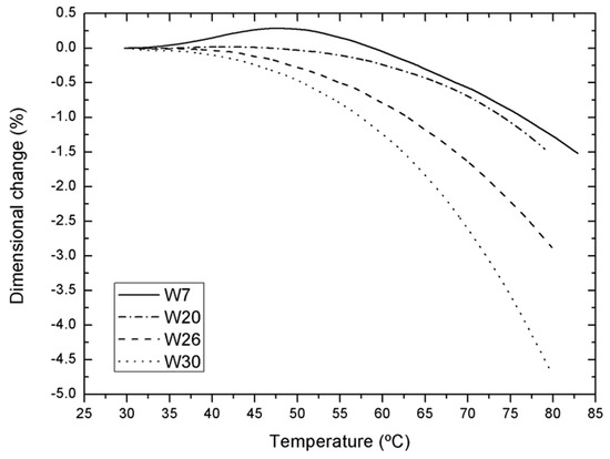
Figure 4.
Study of organic binder plasticity. TMA curves of polysaccharide solution samples with varying water contents (7%, 20%, 26%, and 30%).
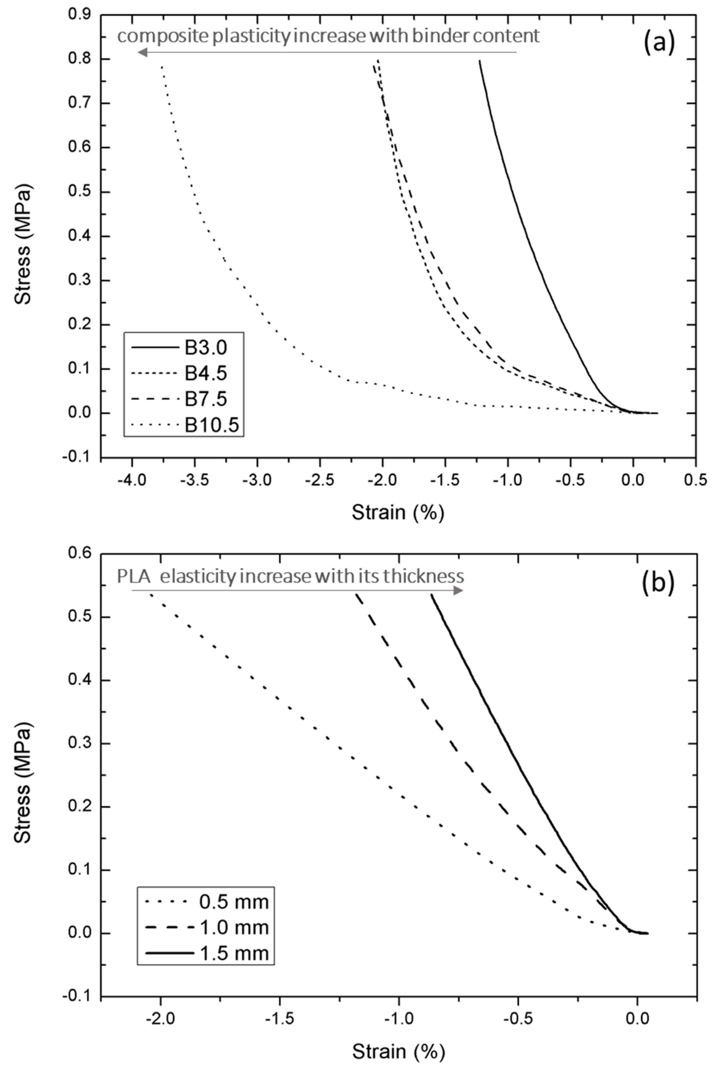
To assess how binder content changes influenced the plasticity of the abrasive composite during the pressing procedure, a series of composite mixtures were tested in compression mode (∅6 × 6 mm samples,) in the Dynamic Mechanical Analyzer (DMA) DMA-Q800, from TA instruments. All tests were conducted in air atmosphere, with a ramp force of 0.3 N/min up to 16 N. The testing conditions are presented in Table 2. Three distinct Y-shaped PLA structures, produced through AM, with branch sections of 1 mm width and thicknesses of 0.5, 1.0, and 1.5 mm, were also tested (Figure 5b).
Table 2.
Study of the plasticity of the cylindrical test specimens of the green abrasive composite by varying the W30 organic binder content.
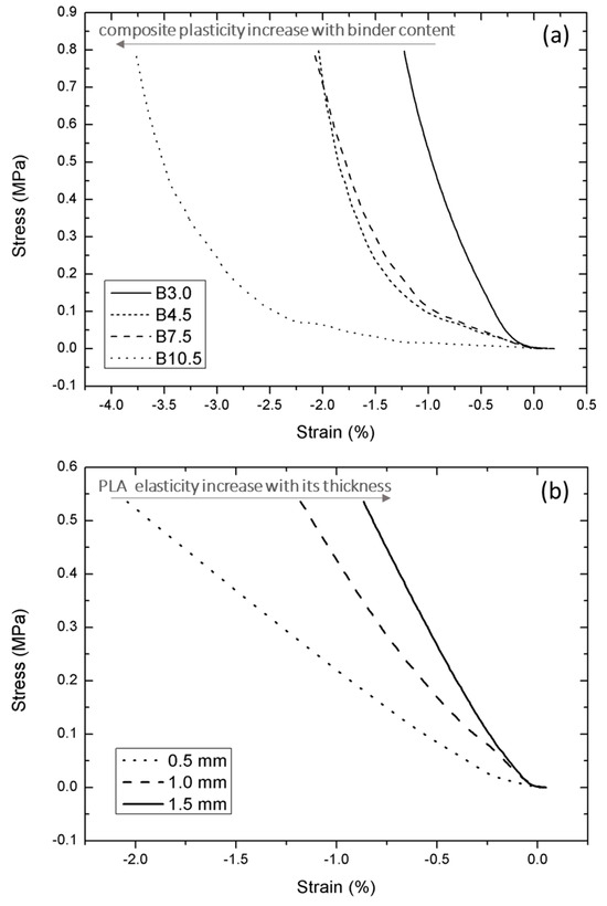
Figure 5.
Stress–strain test curves obtained by DMA assessments, in compression mode, (a) A plasticity study of the cylindrical samples B3, B7.5, and B10.5 (without the PLA structure) of the abrasive composites; (b) an elasticity study of the Y-shaped PLA structure with branch thicknesses of 0.5, 1.0, and 1.5 mm.
As Figure 5a illustrates, as the content of the organic binder W30 in the abrasive composite increased from 3.0% to 10.5%, there was an increase in deformation (strain), regardless of the stress applied to the sample. These findings show that the plasticity of the composite increased as the organic binder content increased. The results of the PLA compression tests (Figure 5b) indicate that, during the pressing step, reducing the thickness of the rectangular branch section in the PLA structure tended to increase its deformation or flexibility.
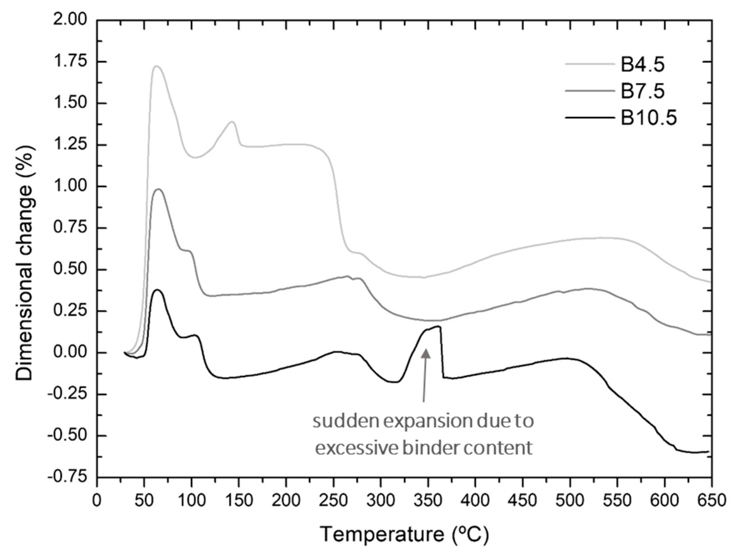
As the organic binder content significantly influenced the composite plasticity (Figure 5a), abrasive composite test specimens with W30 binder content ranging from 4.5% to 10.5% were also produced (Table 2: B4.5, B7.5, and B10.5), incorporating the Y-shaped PLA structure, and subjected to TMA dimensional analysis testing. These tests were performed with the same TMA equipment with a pre-load of 0.01 N, a heating rate of 4 °C/min, in air atmosphere, covering a temperature range from 30 to 650 °C. As illustrated in Figure 6, during the drying phase, the critical material thermal expansion (around 50 °C) was highly influenced by the organic binder content. With an increase in the proportion of the temporary organic binder, these abrasive composites exhibited a significant reduction in thermal expansion (from 1.8% to 0.4%). However, at a 10.5% organic binder content, there was a sudden increase in dimensional change at 350 °C, which was not noted for lower organic binder contents. This effect, seemingly linked to PLA degradation, was consistently observed in different test repetitions. The gases produced during the PLA burning process were encapsulated due to an excessive amount of organic binder, resulting in a sudden expansion at this temperature. This suggests that an excessive amount of organic binder is not advisable, as it prevents the gases from PLA burning to escape.

Figure 6.
TMA of abrasive composites with included PLA structure, manufactured with W30 organic binder contents of 4.5 wt.%, 7.5 wt.%, and 10.5 wt.% (4 °C/min, air atmosphere).
Based on the acquired results, it is apparent that the dimensional variation of the specimens increased in the examined composites with a lower total water content, particularly during the initial heating phase in the thermal drying cycle. Notably, high and abrupt dimensional changes were directly correlated with the likelihood of cracks forming in the abrasive grinding wheel. Hence, comprehending how this initial heating rate influenced the behavior of these composites became paramount. The composite B10.5, featuring 10.5% of organic binder, was excluded due to additional dimensional variations caused by the excessive encapsulation of PLA in the organic binder, hindering the normal polymer combustion around 300 °C (Figure 6, at 350 °C). Consequently, for this analysis, the composite B7.5, with 7.5% of organic binder (Table 2), was selected.
In the abrasive grinding wheel production process, after the pressing stage, the subsequent step is drying, which consists of two primary phases, i.e., a temperature ramp-up to 75 °C followed by a two-hour stage at that temperature. During the heating phase, a substantial amount of water, originating from the organic binder within the composite, is removed. It is crucial to optimize the heating rate in this stage to ensure a controlled and gradual drying of the composite, thus preventing the formation of cracks. To assess the impact of varying heating rates during drying, a dimensional analysis was conducted on the structured abrasive composite with B7.5 composition. Drying heating rates similar to conventional ones were tested to explore alternative values for potential process improvements. Temperature ramp rates of 0.1, 1.0, and 4.0 °C/min were employed in the tests, using the same TMA equipment with a preload of 0.01 N. The tested cylindrical samples were ∅6 x 6 mm in size, with an incorporated Y-shaped structure (Figure 2a).
After the drying process, the organic binder hardens, enhancing the stiffness and mechanical consistency of the green composite. The subsequent step involves sintering the composite. In this study, the green composites were sintered at 950 °C, the same maximum temperature used for conventional wheels, and the same vitrified matrix precursor was employed in the sintering cycle. During this stage, all organic components within the green composite, including the dried organic binder, were eliminated by combustion. Furthermore, in the composites with incorporated PLA structures, PLA was incinerated, leaving behind a structured network of hollow channels. The thermal cycle has to be thoughtfully selected to ensure the removal of the organic components before the vitrified powder softens and forms the vitrified matrix [44]. This precaution was taken to prevent the entrapment of residues within the vitrified matrix, which could result in defects in the composite.
Figure 7 illustrates the impact of the heating rate on the dimensional expansion of the composite for three different heating rates: 0.1 °C/min, 1.0 °C/min, and 4.0 °C/min. A reduction in the heating rate from 4 to 0.1 °C/min significantly diminished the dimensional expansion associated with the introduction of PLA into the composite. Despite the extended drying time, the utilization of a slower heating rate during the heating ramp of the drying cycle substantially mitigated the likelihood of crack formation resulting from the expansion of the composite.
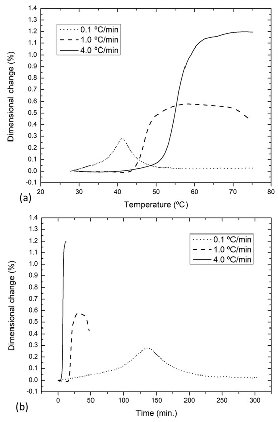
Figure 7.
Dimensional analysis (TMA) of the B7.5 abrasive composite with the incorporated PLA structure in green, as a function of the heating rate (0.1, 1.0, and 4.0 °C/min). (a) Temperature-dependent; (b) time-dependent.
Table 3 summarizes the optimal processing conditions, which were identified for the production of three-dimensionally structured grinding wheels, using this new methodology. Concerning the composition, the findings indicated that W30 served as the most suitable temporary organic binder to facilitate the integration of the PLA structure into the composite, as shown in Figure 4. Additionally, it was determined that, for this purpose, the optimal amount of this binder in the composite was 7.5% (B7.5, Figure 6). During the drying phase, the investigation revealed that a heating rate of 0.1 °C/min provided superior dimensional control of the structured abrasive composite, significantly reducing the likelihood of crack development. In the sintering phase, it was observed that utilizing PLA as a material to create the preform of the channel structure in the composite was advantageous. Its combustion could occur up to 450 °C (Figure 3b), a value lower than the temperature at which the temporary organic binder completed its combustion (Figure 3c), which was 475 °C. This will allow for maintaining roughly the typical sintering thermal cycle for unstructured abrasive composites.
Table 3.
Optimal processing conditions, as an output of the presented research, for the production of structured abrasive composites, using the new methodology.
4. Production and Characterization of Three-Dimensionally Structured Grinding Wheels
Based on the present study and processing conditions showed in Table 3, different abrasive wheels were produced and characterized. Figure 8a shows a typical unstructured reference disc (R). This novel methodology enables the use of various 3D structures with different geometries, which can be tailored depending on the specific application of the abrasive wheel. In this particular case, channels with a honeycomb-inspired geometry, a hexagonal channel structure (H), were designed for face grinding wheels, aiming for a homogeneous coolant flow and an effective removal of chips generated during the grinding operation. Samples featuring that hexagonal channel structure (H) were produced, using a three-layer PLA structure as a channel precursor (Figure 8b). One of the produced abrasive wheels with a 3D hexagonal structure was cut, as depicted in Figure 8c,d. The cross section of this structured abrasive wheel revealed the internal channel structure organized in three layers, fully occupying the thickness of the wheel. The internal network geometry of the channels remained uniform. This approach enabled the production of three-dimensionally structured abrasive wheels throughout their thickness and without any defects, allowing for the accurate prediction of the shape and the dimensions of the channel structure. The channel thickness (~0.52 ± 0.02 mm) and height (~4.54 ± 0.12 mm) were maintained similar to those of the PLA preform, exhibiting only an average overlap of 5.4% among the three layers of channels.
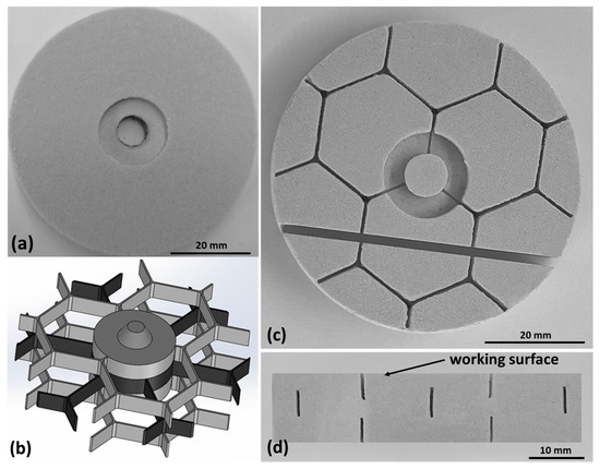
Figure 8.
(a) Unstructured reference disc—R. (b) Perspective view of the PLA structure designed to incorporate the channel network in abrasive grinding wheels. (c) Surface view of the hexagonal structured abrasive grinding wheel prototype—H. (d) Internal view of the grinding wheel—H—with a 3D internal cooling system in the region of the cross-sectional cut.
Table 4 compares the final characteristics of abrasive wheels featuring a 3D internal cooling structure with those of conventional unstructured wheels of the same dimensions. These innovative three-dimensionally structured grinding wheels allowed for a 3.40% increase in the coolant fluid container volume, compared to conventional unstructured wheels, with this augmentation specifically targeted at the wheel/workpiece contact zones. Considering face grinding, the active surface of this hexagonal three-dimensionally structured grinding wheel was reduced by 3.88%. Figure 9a illustrates one of the grooves on the surface of the abrasive wheel with a 3D structure. In Figure 9b, a closer examination reveals the details of the abrasive grains, pores, and vitrified matrix, showing similarity with the typical unstructured wheels, thus demonstrating the validity of this new process methodology.
Table 4.
Final characteristics of the unstructured and structured abrasive wheels.
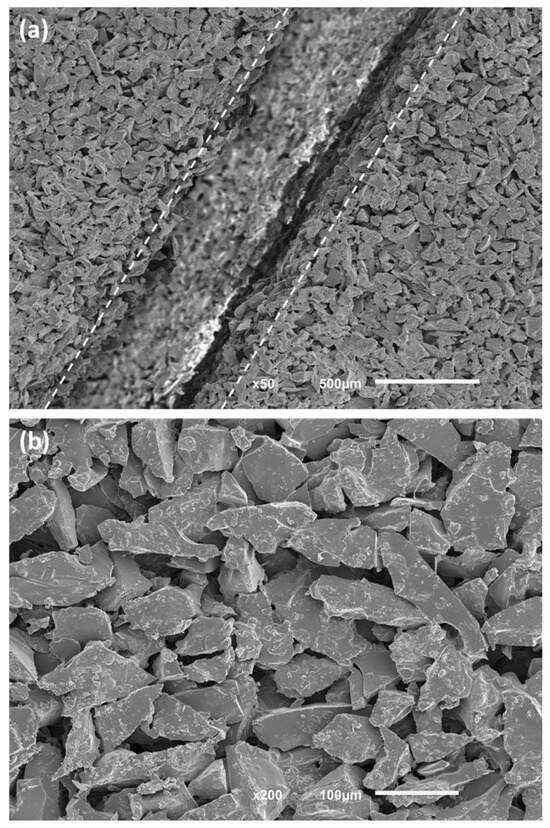
Figure 9.
Abrasive disc with a 3D internal cooling structure system. (a) Groove observed on the surface of the structured abrasive wheel. (b) Detail of abrasive grains and vitrified matrix in the abrasive composite.
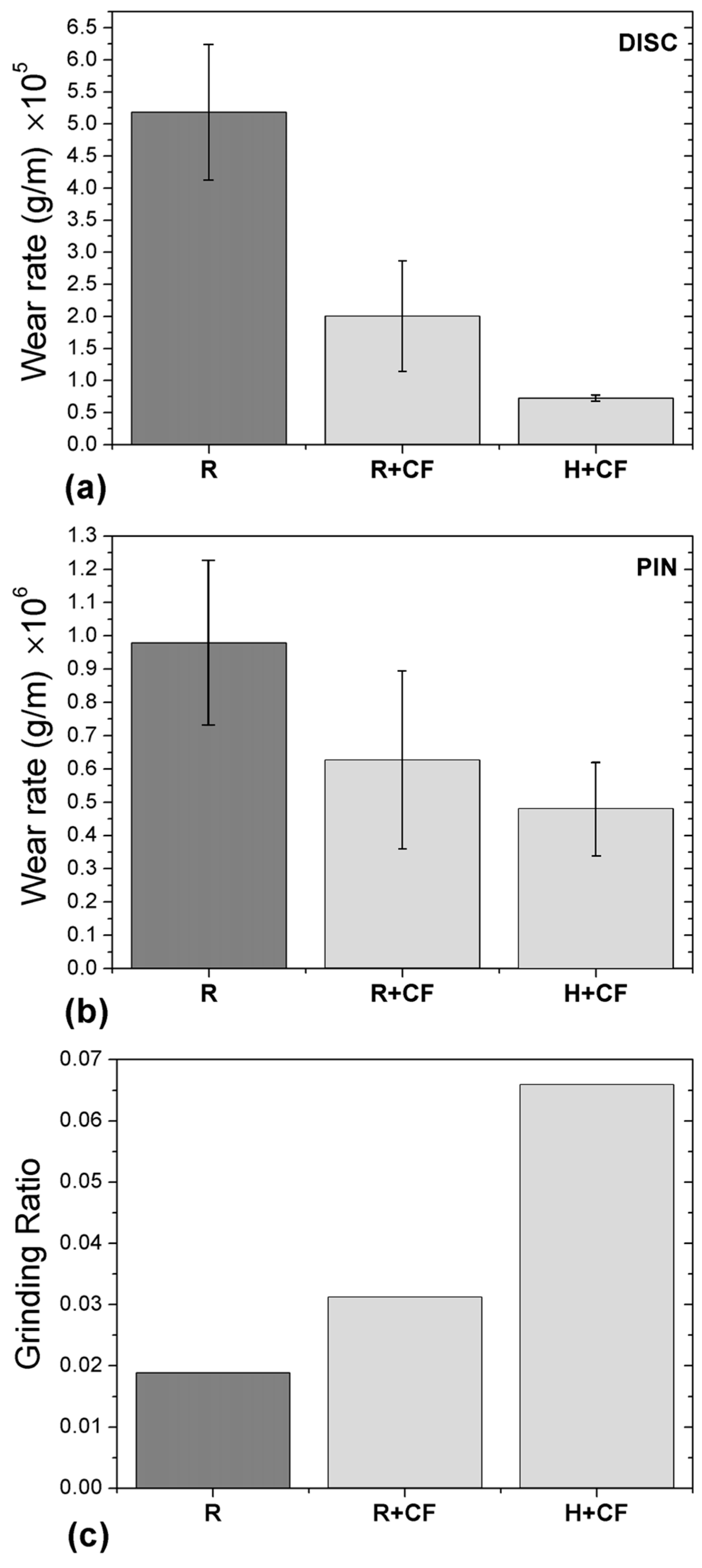
For evaluating the abrasive wear properties, abrasive composite discs with dimensions of Ø62.3 × 8.0 mm were produced in both unstructured (R) and structured hexagonal geometry (H). These evaluations were performed both with and without a flow of 6 mL/min of distilled water, used as a coolant fluid (CF). The R wear discs underwent wear tests both with and without the application of a CF, and the results were compared with those of the H abrasive discs tested with the CF. The wear tests were conducted in a pin-on-disk configuration, with three discs manufactured for each test condition. A 5 mm diameter alumina pin was employed to generate a 24 mm radius wear track on the composite during the wear tests. A 20 N load was applied on the pin, and a sliding speed of 0.5 m/s (222 rpm) was maintained during the tests.
Figure 10 illustrates a substantial 61% reduction in the wear rate of the reference unstructured abrasive discs (R) when the CF was introduced. Under identical test conditions, the wear rate of the alumina pin (corresponding to abrasive R) experienced only a 34% reduction. This resulted in a noteworthy 66% increase in the grinding ratio (pin wear rate/abrasive wear rate), demonstrating a significant improvement in the efficiency of the abrasive wheel in the presence of CF.

Figure 10.
Wear tests results on abrasive discs: R without CF, R+CF, and H+CF. (a) Wear rates of the abrasive discs. (b) Wear rates of the alumina pin counterbody. (c) Grinding ratio for the tested pairs of abrasive discs with an alumina pin.
The inclusion of hexagonal channel structures in the abrasive discs led to a 64% reduction in their wear rate (H+CF). The wear rate of the corresponding alumina counterparts decreased by ~23%. Consequently, when compared to the unstructured abrasive discs (R+CF), there was an impressive 111% increase in the efficiency of the abrasive discs with hexagonal channel structures (H+CF) in the presence of CF. The active surface reduction of 3.88% in the abrasive material (Table 4), from the R+CF to the H+CF tests, created room for the channels, fostering a more efficient cooling of tribological pairs and, as a result, enhancing the grinding ratio of the abrasive discs.
The integration of internal channels facilitated a more uniform distribution of the coolant across the entire grinding surface, which prevented localized overheating and reduced the risk of thermal damage. The channels also helped minimize the clogging of the abrasive surface with wear debris, which is a common problem with conventional grinding wheels [54,55]. As a consequence, by maintaining a cleaner grinding surface, the structured discs maintained their cutting efficiency, and their operational life was extended.
The experimental results underscore the potential of incorporating three-dimensional internal cooling channels in abrasive wheels. The significant improvements in wear rates, grinding ratios, and overall performance metrics highlight the advantages of this innovative design over that of conventional unstructured grinding wheels. These findings open new possibilities for the application of structured grinding wheels in various precision manufacturing processes, where maintaining low temperatures and high efficiency is critical.
5. CFD Simulation Applied to Structured and Unstructured Grinding Wheels
CFD simulations were conducted using Ansys Workbench to investigate how the 3D internal channel structure affected the distribution of the coolant fluid (water) during the pin-on-disc test. The dimensions of the grinding wheel used in the simulation matched those specified in Table 4. The simulation domain included the grinding wheel (both with and without channels), a pin with a 5 mm diameter positioned 0.25 mm from the wheel’s surface, and a 2 mm diameter water inlet located 5 mm from the pin and 1.5 mm from the wheel’s surface (acting as a coolant fluid). A 2 mm thick domain with the same diameter as that of the grinding wheel was created above it to observe the spreading of water during the test. The external faces of the channels were defined as outlets. The geometric model is depicted in Figure 11a.
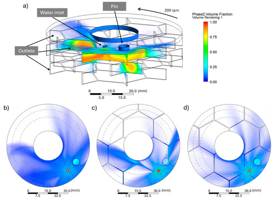
Figure 11.
Tridimensional rendered diagram of the volumetric fraction of water in the cooling channels (a). Surface view of water spreading on an unstructured grinding wheel (b) and on a structured wheel at time 1 (c) and time 2 (d).
In the analysis of the gas–liquid two-phase flow field in the grinding area, air and grinding fluid are considered immiscible [56]. To outline this situation, the Volume of Fluid (VOF) model is most suitable [14,57] and was applied in this study. The following boundary conditions were defined: (i) grinding wheel rotation speed of 200 rpm; (ii) water inlet flow rate of 1 L/min; (iii) outlets at atmospheric pressure.
The rendered diagram illustrates the volumetric fraction distribution of the coolant grinding fluid in the gas–liquid two-phase flow field. This was obtained for a grinding wheel without channels (Figure 11b) and for a grinding wheel with channels under two different scenarios, i.e., when the pin had channels underneath (Figure 11a,c), and when it did not (Figure 11d).
Figure 11 shows that the inlet water followed three possible trajectories: it entered the channels, it remained on the grinding wheel surface, or it was directed outward due to centrifugal forces. Circulation within the channels allowed the fluid to penetrate up to the second layer, as shown in Figure 11a. The fluid dynamics within the cooling channels (Figure 11a) improved the heat dissipation and material removal from the contact zone in comparison with the conventional dynamics resulting from open porosity in unstructured grinding wheels. This efficient fluid distribution allowed for an even more uniform cooling, reducing the grinding wheel surface temperature, while enhancing the outflow of chips and other wear debris. Acting as a carrier agent, the coolant fluid directed the debris away from the workpiece and tool surface, which is particularly critical in high-speed operations to prevent surface damages. Debris transport through channels is crucial for operational efficiency, as it can directly impact the quality of the machined piece and the tool’s lifespan [58].
The results showed that on structured wheels, beyond the usual surface cooling mechanism, a second one occurred depending on the fluid dynamics in the cooling channels. Furthermore, it is noteworthy that the position of the channel network continuously changed with the grinding wheel’s rotation. Hence, the cooling channel intermittently contacted the pin, providing, by heat transfer, effective cooling of the grinding fluid on the grinding surface, while allowing material removal from the pin. Figure 11c,d illustrate two distinct scenarios during a test (identified as time 1 and time 2) as follows: (1) when the channel network was located beneath the pin; (2) when the pin was positioned between two channels. Notably, in Figure 11d, even when the pin and the water outlet were not directly above a channel, the fluid could still penetrate through the channels, demonstrating the efficiency of the channel system in distributing the coolant fluid.
When physically introducing a 3D cooling channel structure into an abrasive disk for pin-on-disc tests (Figure 8d), the results of the experimental wear tests (Figure 10) could be easily correlated with and explained by the coolant fluid distribution observed in the CFD simulation. The wear rate reduction for the abrasive composite and the grinding ratio increase indicate enhancement of the grinding conditions, such as better heat dissipation and more effective removal of wear debris in the contact zone.
The use of this simulation tool is highly valuable, as it enables the comparison of different channel structures. This capability allows for the selection of the most efficient 3D structure geometries, reducing the need for physical testing of the tools and leading to significant material savings and process optimization.
6. Conclusions
This study introduces an innovative approach to manufacturing grinding wheels with 3D internal cooling channel structures. By integrating an organic channel precursor during the pressing step and subsequently removing it during sintering, we achieved a new adjustable design. This allows the channel geometry to be modified based on the type of operation or application, enabling the cooling system to deliver the coolant fluid directly where it is most needed. The optimal process conditions were meticulously determined.
A complete cycle chain is proposed, encompassing materials, composite composition, and process parameters for grinding wheel production. This includes steps such as additive manufactured structures, composite pressing with the inclusion of 3D internal cooling channel structure precursors, drying, and sintering. This advanced methodology led to the production of three-dimensionally structured abrasive prototypes with well-preserved channel geometries after sintering, demonstrating minimal geometric changes (under 5.4%).
The wear tests showed significant performance improvements, with the honeycomb-inspired hexagonal channel structures reducing the wear rates by 64% and enhancing the system efficiency by over 100%. This reflects superior heat dissipation and debris removal capacity, prolonging the wheel lifespan and potentially reducing the coolant fluid usage, thereby mitigating environmental concerns.
The CFD simulations validated enhanced fluid distribution and cooling efficiency in the structured grinding wheels, promoting uniform cooling and efficient debris transport. These results highlight the benefits of integrating 3D internal cooling channels for improved tool durability, performance, and cost-efficiency.
Future research opportunities include exploring different channel geometries and channel precursor materials. Comprehensive studies on the grinding performance, including force measurement, temperature monitoring, and wear analysis compared to those of unstructured wheels, are essential to validate the effectiveness of this solution across diverse machining applications. The surface finish quality of the workpiece can also be assessed through roughness measurements. The method’s versatility extends to flat grinding applications, promising broader utility in precision manufacturing industries.
The proposed wheel process design and the newly developed performant technology will enhance the production chain, reduce material consumption, lower the environmental impact, and improve the final product quality. These achievements align with the Industry 4.0 trends.
Author Contributions
Conceptualization, D.S.; methodology, S.C., M.P. and D.S.; software, S.C.; validation, S.C., P.C., L.C. and M.S.S.; investigation, S.C. and P.C.; resources, D.S.; data curation, J.R.G.; writing—original draft preparation, P.C.; writing—review and editing, S.C. and M.P.; visualization, J.R.G.; supervision, D.S. and M.P.; project administration, D.S. All authors have read and agreed to the published version of the manuscript.
Funding
This work was supported by FCT national funds, under the national support to R&D units grant, through the reference projects UIDB/04436/2020 and UIDP/04436/2020. This work is within the scope of Sharlane Costa Ph.D. degree, in progress, financially supported by the Portuguese Foundation for Science and Technology (FCT) through the PhD grant reference 2021.07352.BD.
Data Availability Statement
Data are contained within the article.
Conflicts of Interest
Author Luís Carvalho was employed by Dragão Abrasivos Lda. The remaining authors declare that the research was conducted in the absence of any commercial or financial relationships that could be construed as a potential conflict of interest.
References
- Zhu, W.L.; Yang, Y.; Li, H.N.; Axinte, D.; Beaucamp, A. Theoretical and Experimental Investigation of Material Removal Mechanism in Compliant Shape Adaptive Grinding Process. Int. J. Mach. Tools Manuf. 2019, 142, 76–97. [Google Scholar] [CrossRef]
- Sun, C.; Zhang, H.; Xu, C.; Hong, Y.; Xiu, S. Influence of the Abrasive Shape-Position Characteristic on the Grinding Thermo-Mechanical Coupling. Surf. Sci. Technol. 2023, 1, 19. [Google Scholar] [CrossRef]
- Kishore, K.; Sinha, M.K.; Singh, A.; Archana; Gupta, M.K.; Korkmaz, M.E. A Comprehensive Review on the Grinding Process: Advancements, Applications and Challenges. Proc. Inst. Mech. Eng. C J. Mech. Eng. Sci. 2022, 236, 10923–10952. [Google Scholar] [CrossRef]
- Tang, J.; Qiu, Z.; Li, T. A Novel Measurement Method and Application for Grinding Wheel Surface Topography Based on Shape from Focus. Measurement 2019, 133, 495–507. [Google Scholar] [CrossRef]
- Kirsch, B. The Impact of Contact Zone Flow Rate and Bulk Cooling on the Cooling Efficiency in Grinding Applying Different Nozzle Designs and Grinding Wheel Textures. CIRP J. Manuf. Sci. Technol. 2017, 18, 179–187. [Google Scholar] [CrossRef]
- Stachurski, W.; Sawicki, J.; Krupanek, K.; Nadolny, K. Numerical Analysis of Coolant Flow in the Grinding Zone. Int. J. Adv. Manuf. Technol. 2019, 104, 1999–2012. [Google Scholar] [CrossRef]
- Stachurski, W.; Dębkowski, R.; Rosik, R.; Święcik, R.; Pawłowski, W. Evaluation of the Influence of the Cooling Method Used During Grinding on the Operating Properties of Ceramic Grinding Wheels Made with Different Abrasives. Adv. Sci. Technol. Res. J. 2023, 17, 1–18. [Google Scholar] [CrossRef]
- Li, H.N.; Axinte, D. Textured Grinding Wheels: A Review. Int. J. Mach. Tools Manuf. 2016, 109, 8–35. [Google Scholar] [CrossRef]
- Zhang, X.; Wen, D.; Shi, Z.; Li, S.; Kang, Z.; Jiang, J.; Zhang, Z. Grinding Performance Improvement of Laser Micro-Structured Silicon Nitride Ceramics by Laser Macro-Structured Diamond Wheels. Ceram. Int. 2020, 46, 795–802. [Google Scholar] [CrossRef]
- Li, H.N.; Axinte, D. On the Inverse Design of Discontinuous Abrasive Surface to Lower Friction-Induced Temperature in Grinding: An Example of Engineered Abrasive Tools. Int. J. Mach. Tools Manuf. 2018, 132, 50–63. [Google Scholar] [CrossRef]
- Nguyen, T.; Zhang, L.C. Performance of a New Segmented Grinding Wheel System. Int. J. Mach. Tools Manuf. 2009, 49, 291–296. [Google Scholar] [CrossRef]
- Krajnik, P.; Drazumeric, R.; Badger, J.; Kopac, J.; Nicolescu, C.M. Particularities of Grinding High Speed Steel Punching Tools. Adv. Mat. Res. 2011, 325, 177–182. [Google Scholar] [CrossRef]
- Chen, X.; Rowe, W.B.; McCormack, D.F. Analysis of the Transitional Temperature for Tensile Residual Stress in Grinding. J. Mater. Process. Technol. 2000, 107, 216–221. [Google Scholar] [CrossRef]
- Mihić, S.; Dražumerič, R.; Pušavec, F.; Badger, J.; Krajnik, P. The Use of Computational Fluid Dynamics in the Analysis of Fluid Flow and Thermal Aspects in Grinding. Proc. Inst. Mech. Eng. B J. Eng. Manuf. 2017, 231, 2103–2111. [Google Scholar] [CrossRef]
- Musavi, S.H.; Razfar, M.; Ganji, D.D. New Application of Ionic Liquid as a Green-Efficient Lubricant. Results Eng. 2024, 21, 101773. [Google Scholar] [CrossRef]
- Tawakoli, T.; Hadad, M.J.; Sadeghi, M.H. Investigation on Minimum Quantity Lubricant-MQL Grinding of 100Cr6 Hardened Steel Using Different Abrasive and Coolant–Lubricant Types. Int. J. Mach. Tools Manuf. 2010, 50, 698–708. [Google Scholar] [CrossRef]
- Ibrahim AM, M.; Wei, L.I.; Mourad AH, I.; Mohamed, A.E.; Abd El-Naby, A.M.; Al Soufi, M.S.; Ezzat, M.F.; Elsheikh, A. Cooling and Lubrication Techniques in Grinding: A State-of-the-Art Review, Applications, and Sustainability Assessment. Chin. J. Aeronaut. 2023, 36, 76–113. [Google Scholar] [CrossRef]
- Shokoohi, Y.; Khosrojerdi, E.; Rassolian Shiadhi, B.H. Machining and Ecological Effects of a New Developed Cutting Fluid in Combination with Different Cooling Techniques on Turning Operation. J. Clean. Prod. 2015, 94, 330–339. [Google Scholar] [CrossRef]
- Hadad, M. An Experimental Investigation of the Effects of Machining Parameters on Environmentally Friendly Grinding Process. J. Clean. Prod. 2015, 108, 217–231. [Google Scholar] [CrossRef]
- Garcia, M.V.; Lopes, J.C.; Diniz, A.E.; Rodrigues, A.R.; Volpato, R.S.; de Angelo Sanchez, L.E.; de Mello, H.J.; Aguiar, P.R.; Bianchi, E.C. Grinding Performance of Bearing Steel Using MQL under Different Dilutions and Wheel Cleaning for Green Manufacture. J. Clean. Prod. 2020, 257, 120376. [Google Scholar] [CrossRef]
- Costa, S.; Pereira, M.; Ribeiro, J.; Soares, D. Texturing Methods of Abrasive Grinding Wheels: A Systematic Review. Materials 2022, 15, 8044. [Google Scholar] [CrossRef] [PubMed]
- Mohamed, A.-M.O.; Bauer, R.; Warkentin, A. Application of Shallow Circumferential Grooved Wheels to Creep-Feed Grinding. J. Mater. Process. Technol. 2013, 213, 700–706. [Google Scholar] [CrossRef]
- Dogra, M.; Sharma, V.S.; Dureja, J.S.; Gill, S.S. Environment-Friendly Technological Advancements to Enhance the Sustainability in Surface Grinding- A Review. J. Clean. Prod. 2018, 197, 218–231. [Google Scholar] [CrossRef]
- Tian, Y.; Wang, J.; Hu, X.; Song, X.; Han, J.; Wang, J. Energy Prediction Models and Distributed Analysis of the Grinding Process of Sustainable Manufacturing. Micromachines 2023, 14, 1603. [Google Scholar] [CrossRef] [PubMed]
- Suto, T.; Waida, T.; Noguchi, H.; Inoue, H. High Performance Creep Feed Grinding of Difficult-to-Machine Materials with New-Type Wheels. Bull. Jpn. Soc. Precis. Eng. 1990, 24, 39–44. [Google Scholar]
- Wen, D.; Wan, L.; Zhang, X.; Li, C.; Ran, X.; Chen, Z. Grinding Performance Evaluation of SiC Ceramic by Bird Feather-like Structure Diamond Grinding Wheel. J. Manuf. Process. 2023, 95, 382–391. [Google Scholar] [CrossRef]
- Chen, Z.; Zhang, X.; Wen, D.; Li, S.; Wang, X.; Gan, L.; Rong, X. Improved Grinding Performance of SiC Using an Innovative Bionic Vein-like Structured Grinding Wheel Optimized by Hydrodynamics. J. Manuf. Process. 2023, 101, 195–207. [Google Scholar] [CrossRef]
- Yu, H.; Zhang, W.; Zhang, S.; Zhang, J.; Han, Z. Optimization of Hydrodynamic Properties of Structured Grinding Wheels Based on Combinatorial Bionics. Tribol. Int. 2022, 173, 107651. [Google Scholar] [CrossRef]
- Wang, C.Y.; Zhang, L.; Yang, C.F. Analysis and Simulation of Air Flow Field Surrounding Grinding Wheel. Adv. Mat. Res. 2014, 1027, 12–15. [Google Scholar] [CrossRef]
- Zhang, X.; Wang, Z.; Shi, Z.; Shi, Z.; Jiang, R.; Kang, Z. Improved Grinding Performance of Zirconia Ceramic Using an Innovative Biomimetic Fractal-Branched Grinding Wheel Inspired by Leaf Vein. Ceram. Int. 2020, 46, 22954–22963. [Google Scholar] [CrossRef]
- Riebel, A.; Bauer, R.; Warkentin, A. Investigation into the Effect of Wheel Groove Depth and Width on Grinding Performance in Creep-Feed Grinding. Int. J. Adv. Manuf. Technol. 2020, 106, 4401–4409. [Google Scholar] [CrossRef]
- Ding, N.; Jiang, S.; Duan, J.; Liu, C.; Cui, S. Design of New Slotted Structured Grinding Wheel. In Proceedings of the Journal of Physics: Conference Series; IOP Publishing: Bristol, UK, 2020; Volume 1635, p. 12013. [Google Scholar]
- Zhang, Y.; Fang, C.; Huang, G.; Cui, C.; Xu, X. Numerical and Experimental Studies on the Grinding of Cemented Carbide with Textured Monolayer Diamond Wheels. Int. J. Refract. Met. Hard Mater. 2019, 84, 105022. [Google Scholar] [CrossRef]
- Wu, S.; Zhang, F.; Ni, Y.; Chen, F.; Yan, Z. Grinding of Alumina Ceramic with Microtextured Brazed Diamond End Grinding Wheels. Ceram. Int. 2020, 46, 19767–19784. [Google Scholar] [CrossRef] [PubMed]
- Li, C.; Shi, Z.J.; Zhang, X.H.; Shi, Z.Y.; Li, S.; Jiang, R.Y.; Wang, Z.R.; Zhang, Z.C. An Investigation on Grinding Mechanism of Alumina Ceramic Using a Grooved Grinding Wheel with Inclined Cross Section. Int. J. Adv. Manuf. Technol. 2020, 111, 2391–2399. [Google Scholar] [CrossRef]
- Zhang, X.; Jiang, J.; Li, S.; Wen, D. Laser Textured Ti-6Al-4V Surfaces and Grinding Performance Evaluation Using CBN Grinding Wheels. Opt. Laser Technol. 2019, 109, 389–400. [Google Scholar] [CrossRef]
- Li, H.N.; Xie, K.G.; Wu, B.; Zhu, W.Q. Generation of Textured Diamond Abrasive Tools by Continuous-Wave CO2 Laser: Laser Parameter Effects and Optimisation. J. Mater. Process. Technol. 2020, 275, 116279. [Google Scholar] [CrossRef]
- Moreno, M.G.; Ruiz, J.Á.; Azpeitia, D.B.; González, J.I.M.; Fernández, L.G. Friction Improvement via Grinding Wheel Texturing by Dressing. Int. J. Adv. Manuf. Technol. 2020, 107, 4939–4954. [Google Scholar] [CrossRef]
- Du, Z.; Zhang, F.; Xu, Q.; Huang, Y.; Li, M.; Huang, H.; Wang, C.; Zhou, Y.; Tang, H. Selective Laser Sintering and Grinding Performance of Resin Bond Diamond Grinding Wheels with Arrayed Internal Cooling Holes. Ceram. Int. 2019, 45, 20873–20881. [Google Scholar] [CrossRef]
- Barmouz, M.; Azarhoushang, B.; Zahedi, A.; Rabiei, F.; Steinhäuser, F. Progress in Grinding Performance by Additive Manufacturing of Grinding Wheels Integrated with Internal Venturi Cooling Channels and Surface Slots. J. Manuf. Process. 2023, 99, 485–500. [Google Scholar] [CrossRef]
- Li, H.N.; Zhao, Y.J.; Cao, S.; Chen, H.; Wu, C.; Qi, H.; Sun, X.; Wang, H.; Li, C.; Liu, G. Controllable Generation of 3D Textured Abrasive Tools via Multiple-Pass Laser Ablation. J. Mater. Process. Technol. 2021, 295, 117149. [Google Scholar] [CrossRef]
- Groover, M.P. Fundamentals of Modern Manufacturing: Materials, Processes, and Systems, 7th ed.; John Wiley & Sons: Hoboken, NJ, USA, 2020; ISBN 978-1-119-47529-3. [Google Scholar]
- Capela, P.; Costa, S.; Souza, M.S.; Carvalho, S.; Pereira, M.; Carvalho, L.; Gomes, J.R.; Soares, D. Wear Behavior of a New Composite Formulation, with TEOS Addition, for Abrasive Vitrified Grinding Wheels. Wear 2023, 512–513, 204524. [Google Scholar] [CrossRef]
- Capela, P.; Carvalho, S.F.; Guedes, A.; Pereira, M.; Carvalho, L.; Correia, J.; Soares, D.; Gomes, J.R. Effect of Sintering Temperature on Mechanical and Wear Behaviour of a Ceramic Composite. Tribol. Int. 2018, 120, 502–509. [Google Scholar] [CrossRef]
- Jackson, M.J.; Mills, B. Materials Selection Applied to Vitrified Alumina & CBN Grinding Wheels. J. Mater. Process. Technol. 2000, 108, 114–124. [Google Scholar] [CrossRef]
- Capela, P.; Faria, L.; Junior, C.; Carvalho, L.; Guedes, A.; Pereira, M.; Soares, D. Study and Optimization of the Drying Process of a Ceramic Abrasive Composite. Int. J. Appl. Ceram. Technol. 2016, 13, 308–315. [Google Scholar] [CrossRef]
- Liu, J.H.; Pei, Z.J.; Fisher, G.R. Grinding Wheels for Manufacturing of Silicon Wafers: A Literature Review. Int. J. Mach. Tools Manuf. 2007, 47, 1–13. [Google Scholar] [CrossRef]
- Zhang, Z.; Yan, J.; Kuriyagawa, T. Manufacturing Technologies toward Extreme Precision. Int. J. Extrem. Manuf. 2019, 1, 022001. [Google Scholar] [CrossRef]
- Lin, K.-H.; Peng, S.-F.; Lin, S.-T. Sintering Parameters and Wear Performances of Vitrified Bond Diamond Grinding Wheels. Int. J. Refract. Met. Hard Mater. 2007, 25, 25–31. [Google Scholar] [CrossRef]
- Prathipa, R.; Sivakumar, C.; Shanmugasundaram, B. Biodegradable Polymers for Sustainable Packaging Applications. Int. J. Mech. Eng. Technol. 2018, 9, 293–303. [Google Scholar]
- Farah, S.; Anderson, D.G.; Langer, R. Physical and Mechanical Properties of PLA, and Their Functions in Widespread Applications—A Comprehensive Review. Adv. Drug Deliv. Rev. 2016, 107, 367–392. [Google Scholar] [CrossRef]
- Ruz-Cruz, M.A.; Herrera-Franco, P.J.; Flores-Johnson, E.A.; Moreno-Chulim, M.V.; Galera-Manzano, L.M.; Valadez-González, A. Thermal and Mechanical Properties of PLA-Based Multiscale Cellulosic Biocomposites. J. Mater. Res. Technol. 2022, 18, 485–495. [Google Scholar] [CrossRef]
- Schneider, M.; Günter, C.; Taubert, A. Co-Deposition of a Hydrogel/Calcium Phosphate Hybrid Layer on 3D Printed Poly(Lactic Acid) Scaffolds via Dip Coating: Towards Automated Biomaterials Fabrication. Polymers 2018, 10, 275. [Google Scholar] [CrossRef] [PubMed]
- Vignesh, R.; Arunachalam, N. Design and Development of Spiral Grooved Grinding Wheel and Their Influence on the Performance of Vertical Surface Grinding Process. Procedia Manuf. 2021, 53, 251–259. [Google Scholar] [CrossRef]
- Denkena, B.; Grove, T.; Göttsching, T. Grinding with Patterned Grinding Wheels. CIRP J. Manuf. Sci. Technol. 2015, 8, 12–21. [Google Scholar] [CrossRef]
- Liu, S.; Jiang, J.; Chen, X. Study on Characteristics of Two Phase Flow Field in Grinding Zone of Large Spiral Angle Groove Wheel. Acad. J. Sci. Technol. 2023, 5, 100–103. [Google Scholar] [CrossRef]
- Kumar, A.; Bhardwaj, R.; Joshi, S.S. Coolant Flow in Drilling Titanium Considering Two Phase Boiling. Int. J. Mech. Sci. 2022, 230, 107543. [Google Scholar] [CrossRef]
- Chen, M.; Peng, R.; Li, A.; Xiao, X.; Zhao, L. Assessment of Surface Structure Optimization in Internal Cooling Grinding. Int. J. Adv. Manuf. Technol. 2022, 123, 2139–2155. [Google Scholar] [CrossRef]


Disclaimer/Publisher’s Note: The statements, opinions and data contained in all publications are solely those of the individual author(s) and contributor(s) and not of MDPI and/or the editor(s). MDPI and/or the editor(s) disclaim responsibility for any injury to people or property resulting from any ideas, methods, instructions or products referred to in the content. |
© 2024 by the authors. Licensee MDPI, Basel, Switzerland. This article is an open access article distributed under the terms and conditions of the Creative Commons Attribution (CC BY) license (https://creativecommons.org/licenses/by/4.0/).