Abstract
Utilizing additive manufacturing (AM) techniques with shape memory alloys (SMAs) like NiTi shows great promise for fabricating highly flexible and functionally superior 3D metallic structures. Compared to methods relying on powder feedstocks, wire-based additive manufacturing processes provide a viable alternative, addressing challenges such as chemical composition instability, material availability, higher feedstock costs, and limitations on part size while simplifying process development. This study presented a novel approach by thoroughly assessing the printability of Ni-rich Ni55.94Ti (Wt. %) SMA using the wire laser-directed energy deposition (WL-DED) technique, addressing the existing knowledge gap regarding the laser wire-feed metal additive manufacturing of NiTi alloys. For the first time, the impact of processing parameters—specifically laser power (400–1000 W) and transverse speed (300–900 mm/min)—on single-track fabrication using NiTi wires in the WL-DED process was examined. An optimal range of process parameters was determined to achieve high-quality prints with minimal defects, such as wire dripping, stubbing, and overfilling. Building upon these findings, we printed five distinct cubes, demonstrating the feasibility of producing nearly porosity-free specimens. Notably, this study investigated the effect of energy density on the printed part density, impurity pick-up, transformation temperature, and hardness of the manufactured NiTi cubes. The results from the cube study demonstrated that varying energy densities (46.66–70 J/mm3) significantly affected the quality of the deposits. Lower to intermediate energy densities achieved high relative densities (>99%) and favorable phase transformation temperatures. In contrast, higher energy densities led to instability in melt pool shape, increased porosity, and discrepancies in phase transformation temperatures. These findings highlighted the critical role of precise parameter control in achieving functional NiTi parts and offer valuable insights for advancing AM techniques in fabricating larger high-quality NiTi components. Additionally, our research highlighted important considerations for civil engineering applications, particularly in the development of seismic dampers for energy dissipation in structures, offering a promising solution for enhancing structural performance and energy management in critical infrastructure.
1. Introduction
The NiTi alloy, commonly referred to as nitinol, is recognized as a versatile functional material valued for its shape memory effects and superelasticity, making it highly suitable for a range of applications, including those in biomedical, aerospace, and civil engineering [1,2]. In particular, the exceptional properties of NiTi alloys are highly beneficial in civil engineering, where their ability to endure substantial strains without permanent damage is crucial. This makes them ideal for energy dissipation applications, such as seismic dampers, which mitigate vibrations from earthquakes and wind. By enhancing the resilience and longevity of structures, NiTi-based dampers address the growing demand for durable infrastructure capable of withstanding natural disasters and the challenges posed by aging buildings [3,4]. In recent years, additive manufacturing (AM) techniques have opened new possibilities for fabricating NiTi components with complex geometries, reduced material waste, and enhanced functionality and production rates [5,6,7].
Among AM methods, laser powder bed fusion (LPBF) [8,9,10,11,12,13,14,15,16,17,18,19] and direct energy deposition (DED) have emerged as practical options for producing customized NiTi parts [20,21,22,23]. DED has attracted significant attention for its ability to handle large material volumes and fabricate parts with superior accuracy and surface quality. This technique involves the utilization of a power source, such as a laser, plasma arc, or electron beam, in combination with a feedstock comprising either wire or powder [24,25,26,27]. Both wire and powder feeding methods yield comparable material and microstructural characteristics.
Powder-based DED, in particular, is effective for fabricating complex NiTi components, enabling precise control over microstructure and mechanical properties. Numerous studies explored the feasibility of using NiTi powder with DED techniques to manufacture high-quality, efficient parts. Kumar et al. [28] showed that increasing laser power reduces porosity but leads to the formation of Ti2Ni precipitates, enhancing hardness at the cost of reduced recovery properties. Similarly, Baran and Polanski [29] reported that lower laser scan speeds alter grain structure and promote secondary phase formation, influencing transformation temperatures and mechanical performance. Zheng et al. [30] found that while DED techniques result in higher strengths, they also exhibit lower elongation compared to selective laser melting (SLM), mainly due to porosity and phase precipitation. Despite the advantages of utilizing powder in the DED technique, it presents challenges, including contamination during preparation and deposition, limited material availability and component size restrictions, and increased production time and costs due to additional powder handling and recycling steps. To overcome these limitations, wire-based DED processes were explored, offering advantages such as enhanced composition control, reduced contamination risks, and higher deposition rates. In the case of NiTi, wire is the most widely available semi-finished form of the material. According to industry estimates, approximately 80–90% of all NiTi material produced for industrial applications is in wire form. The widespread availability of wire in diameters from 0.0127 mm to 1.5 mm make it an attractive option for DED, effectively addressing many challenges of powder-based DED [31,32,33]. Wire-based DED methods, including wire arc additive manufacturing (WAAM), wire laser DED (WL-DED), and electron beam DED, have gained significant attention for medium- to large-scale applications. These methods offer high deposition rates, cost-effectiveness, and reduced material waste by eliminating the need for extensive powder handling
Wire arc additive manufacturing (WAAM) emerged as an effective technique for fabricating NiTi components, particularly in large-scale applications [34,35,36]. Extensive studies examined the impact of process parameters on the microstructure and functional properties of WAAM-fabricated NiTi alloys [37,38,39]. Wang et al. [40] studied the effect of deposition current on WAAM-fabricated NiTi components. It was found that deposition current significantly influences microstructure and properties, with lower currents improving functional performance by promoting favorable crystal orientation and finer grains. Liu et al. [41] emphasized the importance of optimized deposition speed for achieving uniform microstructures and enhancing superelasticity and shape memory properties. Yu, Lin et al. [37] showed that CMT-based WAAM for NiTi alloys results in strong interlayer bonding and minimal defects, with optimal mechanical properties occurring at specific distances from the substrate, highlighting the importance of precise control over deposition parameters.
Despite its advantages, WAAM faces challenges due to high heat input, which can negatively affect part quality through melt pool geometry issues, residual stress, and distortion [42]. Laser- and electron-based DED processes offer more focused energy, favoring near-net-shape manufacturing [24]. However, electron beam DED experiences reduced precision, material distortion, and higher costs due to vacuum requirements [43]. These limitations highlight the potential benefits of WL-DED, which provides a more controlled deposition environment. WL-DED enables precise control over key process parameters, such as laser power, travel speed, and wire feed rate, leading to improved mechanical properties and enhanced microstructural integrity in NiTi alloys. The feasibility of the LW-DED method was validated with a variety of materials, including Ti-alloys, Al-alloys, and stainless steels [24,42,43,44,45]. Several studies emphasized the significant impact of these parameters on the final product quality. Typically, the development of process parameters begins with evaluating single tracks to identify optimal deposition conditions, which are then applied to fabricate 3D parts. Akbari et al. [46] developed a robotized laser wire additive manufacturing system to evaluate process feasibility through diverse geometry fabrication. Challenges such as droplet formation, wire dripping, adherence issues, irregular initial layer deposition, and wire tip deviations were identified, leading to the need for optimizing process parameters. Their findings showed that higher laser power reduced bead height and increased width, while higher travel speed decreased height with little effect on width. Increased wire feed speed raised height and reduced width. Wang et al. [47] studied the WL-DED processing of AA7075 to minimize porosity in thin-wall structures. They adjusted laser power in the initial layers and stabilized it during the build, finding that porosity was mainly influenced by energy input and the wire feed rate to scan speed ratio. Higher energy levels significantly reduced porosity, improving the overall quality of the structure. Motta et al. [48] optimized WL-DED process parameters using stainless steel wire, creating a process map to identify stable deposition regions. Multi-layer tests showed that a power decay strategy reduced defects at higher power levels compared to constant power, emphasizing the importance of adaptive parameter control for ensuring process stability.
Previous studies on additive manufacturing (AM) of NiTi alloys primarily focused on techniques such as powder-based DED, LPBF, and WAAM. However, the application of WL-DED in processing NiTi alloys remains relatively unexplored. Given the novelty of WL-DED technology and its potential for NiTi application, there is a pressing need to develop optimized processes for manufacturing high-quality components. Thorough optimization and precise selection of process parameters are essential in manufacturing NiTi components that meet the precise requirements of application-specific shape memory properties. This study aimed to optimize the process parameters, including laser power, transverse speed to fabricate defect-free NiTi components using laser wire DED. Using the oxide-free Ni55.94Ti (Wt. %) wire, a series of single tracks were fabricated with laser power ranging from 400 to 1000 W and transverse speed of 300–900 mm/min. The melt pool shape and geometry were evaluated to create a process map and identify the optimal region for fabricating dense parts. The identified parameters, along with their associated energy densities, were then applied to fabricate cubes for comprehensive analysis. This analysis involved evaluating various properties, including density, impurity pick-up, phase transformation temperature, and hardness, essential characteristics for application in dampers, where the shape memory properties are critical for performance.
2. Materials and Methods
2.1. Materials
In this study, Ni-rich Ni55.94Ti (Wt. %) wire with a diameter of 1.14 mm, supplied by Fort Wayne Metals (FWM, South Bend, IN, USA), was employed as the starting material. The substrate material consisted of NiTi cast supplied by FWM, machined to dimensions of 140 mm × 140 mm × 12 mm, with its surfaces cleaned using isopropanol before printing. The chemical compositions of both wire and the substrate are provided in Table 1.

Table 1.
Chemical composition of the Ni-rich NiTi wire and substrate (Wt. %).
Prior to the experiments, the Ni-rich NiTi wire was subjected to several processing steps, including straight annealing and cold drawing, to achieve approximately 40–50% cold work. In the final processing step, the Ni-rich NiTi wire was heat-treated at 500 °C for one minute to induce the desired microstructural changes. This heat treatment facilitated the recrystallization of the cold-drawn nitinol wire, a crucial step for optimizing its functional properties [49,50,51,52,53].
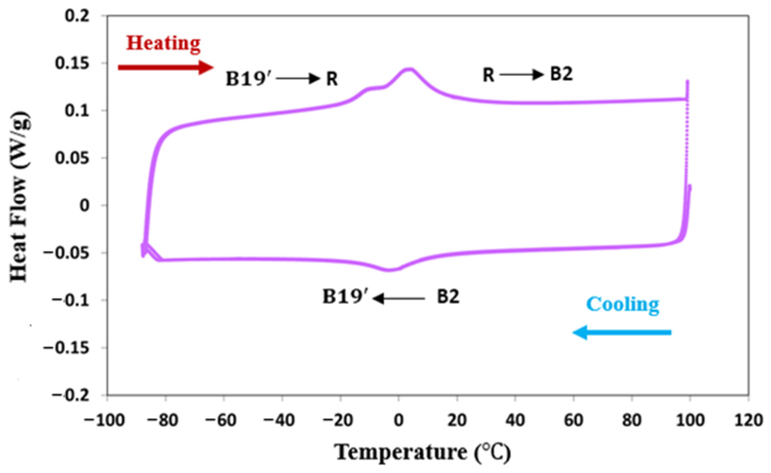
Differential scanning calorimetry (DSC) analysis was performed on the heat-treated wire to characterize its phase transformation behavior, using a TA Instruments DSC 250 (Waters Discovery, New Castle, DE, USA), employing a heating/cooling rate of 10 °C/min. Each sample was subjected to two cycles between −85 and 100 °C to ensure thorough analysis. Nitrogen was used as a protective gas to prevent oxidation during the process. The DSC curve and the corresponding transformation temperatures are presented in Figure 1 and Table 2. The heat-treated wire exhibited a single-stage transformation from the B2 austenite phase to the B19’ martensite phase during cooling. Upon heating, the wire showed a two-stage transformation, first from B19’ to the R-phase and then from the R-phase to the B2 austenite phase.

Figure 1.
DSC graph of the as-received oxide-free NiTi wire.
Table 2.
Transformation temperature of the oxide-free NiTi wire.
The small hysteresis observed in the DSC curves indicates that the peaks correspond to the R-B2 transformation. This behavior is attributed to the high nickel content in the alloy, which results in the formation of a high density of tiny Ni4Ti3 precipitates within the B2 matrix [54,55,56] These precipitates enhance the shape memory behavior of the NiTi alloys primarily by reducing the Ni content in the matrix, which increase the martensitic transformation temperatures and improves thermal and mechanical properties. They create localized stress fields that facilitate nucleation of the martensitic transformation, ensuring better control and reversibility of the shape memory effect. Additionally, these precipitates strengthen the matrix by their coherent interfaces, reducing plastic deformation during phase transformation cycles and stabilizing the desired phases for enhanced shape recovery and operational reliability. In addition to the influence of Ni4Ti3 precipitates, cold working introduces dislocations, which are associated with deformation texture and can influence phase transformations. The DSC analysis confirms the presence of the R-phase in the cold-worked wire. While DSC cannot directly attribute the formation of the R-phase to dislocations, the literature suggests that dislocations generated during cold working are a potential factor contributing to its formation [49,57]. During heat treatment, aging also takes place, leading to the formation of Ni4Ti3 precipitates. For the cold-worked specimen, heat treatment induces recovery processes that relax the internal stresses in the matrix and cause partial recrystallization [51,58]. These microstructural changes help stabilize the R-phase during heating, contributing to the observed transformation behavior.
2.2. Additive Manufacturing of NiTi Parts
The fabrication process utilized a commercial DED printer (Meltio M450, DIRECTEDMETAL 3D, S.L., Linares, Jaen, Spain) equipped with six constant wave diode lasers, each with a power of 200 W and a wavelength of 976 nm (Figure 2a). Figure 2b shows the printing chamber, containing a substrate, coaxial wire deposition head with material supply, shielding gas nozzle, and lasers. Each individual laser beam exhibited a near-Gaussian energy distribution with a diameter of approximately 1 mm at the deposition plane (Figure 2c). The alignment of six laser beams enabled coaxial feeding and sufficient energy coverage for fully melting the NiTi wire. Laser alignment played a critical role in ensuring the quality of the printed parts and preventing defects. Therefore, periodic alignment checks were necessary to verify the correct laser positioning. Inert argon gas (25 L/min) and air conditioners were utilized to minimize oxidation and excessive heating during the laser-deposition process, maintaining a pressure of 4 bars in the print chamber. The Meltio Horizon 1.2.0 software was employed to generate the codes controlling the scanning pattern. Throughout the process, the deposition head remained stationary while the building platform was moved both laterally and vertically.
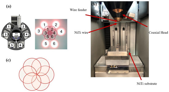
Figure 2.
(a) Laser numbers from top view of the print head, (b) laser-wire DED printing chamber, (c) correct laser alignment.
Sample fabrication and characterization were divided into two steps: (1) single tracks and (2) bulk samples.
2.2.1. Single-Track Experiments
A comprehensive understanding of the melt pool behavior, particularly its shape and stability, is essential for ensuring the production of defect-free 3D printed parts. These characteristics are significantly influenced by two key processing parameters: laser power (P, in watts) and traverse speed (V, in mm/min). Therefore, knowledge of how these parameters affect the melt pool geometry is essential for successful 3D printing with minimal defects. To investigate the relationship between processing parameters and melt pool dimensions, single-track experiments were conducted. Thirty single tracks were fabricated using various combinations of laser power and transverse speed to observe their impact on the melt pool’s shape and geometry. Single tracks, each 20 mm long with 5 mm spacing between adjacent tracks, were printed on the NiTi substrate. The NiTi substrate was used to mitigate potential variations in material composition between the wire and the substrate, which could affect the melt pool characteristics. The selection of process parameters was based on their linear energy density, which combines laser power and transverse speed to represent the total energy delivered to the material during printing. Laser power and transverse speed were selected as the primary variables influencing energy density as follows:
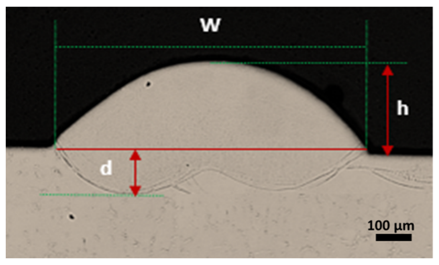
where LED is linear energy density, P is laser power, and V is transverse speed, as commonly found in welding literature [59,60]. A 6 × 5 test matrix, with parameters listed in Table 3, was used to fabricate single tracks. This characterization process allowed for narrowing down the parameters to identify a suitable processing window for further investigation. Optimal single-track parameter sets were considered to have a consistent deposition and be free from characteristic build defects including lack of fusion, wire stubbing, and wire dripping. After fabrication, top-view images of the single-tracks were captured using optical microscopy, OM, Keyence VHX-6000 (Keyence, Itasca, IL, USA, and the width of each single track was measured to assess track continuity. Electrical discharge machining (EDM 350, GF Machining Solutions LLC, Lincolnshire, IL, USA) was used to cut cross-section samples from the NiTi substrate, which were subsequently ground to 1200 grit and polished using a 1 µm colloidal silica solution. Geometrical measurements such as single-track width (w), height (h), and depth of the melt pool (d), as shown in Figure 3. In the final processing step, the Ni-rich NiTi wire was heat-treated at 500 °C for one minute to induce the desired microstructural changes, were determined using the OM.
Table 3.
Process parameters (P, V) and corresponding linear energy density for the NiTi single-track process.
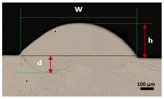
Figure 3.
Geometrical measurements of single-track. w: single-track width; h: single-track height; d: penetration depth.
2.2.2. Fabrication of Bulk Samples
After developing the initial printability map, specific combinations of laser power, transverse speed, and wire feed rate were selected from the printable region. These parameters were then used to fabricate bulk samples for further analysis. This analysis investigated the effects of processing parameters on the microstructure, phase transformation behavior, and hardness of the fabricated NiTi samples.
To ensure the reliability of the results, four cube samples, each measuring 20 mm × 20 mm × 20 mm, were fabricated for each of the five sets of optimized parameters identified from the smooth region of the printability map. The results presented in this paper are based on the average measurements obtained from these four cubes. All prints were produced using a bi-directional scanning strategy at ±45°, alternating by 90° with each layer. This approach ensured proper anisotropy and addressed potential gaps in complex geometries where the deposited line width exceeds the gap size. This scanning approach minimizes residual stress accumulation along specific directions [61]. An overlap of 60% between infill lines was set to minimize discontinuities during the deposition process. THe volumetric energy density (VED) for each cube was calculated, and the results were compared based on increasing energy density as follows [62]:
where the wire feed rate determines the amount of material deposited. The layer height was kept constant at 1 mm for all cubes.
2.3. Material Characterization
After cube fabrication, each sample was cut from the substrate using an EDM machine. To avoid the influence of the heat-affected zone (HAZ) on the cubes, EDM was performed at a very low speed and a few millimeters away from the HAZ. This approach minimized the thermal impact and prevented undesired changes in the phase transformation temperatures, such as the precipitation of nickel-rich phases. The cubes were then cross-sectioned into five segments parallel to the building direction. Three segments were mounted in epoxy resin along the build direction, ground to 1200 grit, and polished with colloidal silica solution. These prepared segments were utilized for visualizing melt pool formation and conducting density measurements via image analysis. Quantitative density measurements were conducted on three sections using an optical microscope (Keyence VHX 6000, Itasca, IL, USA) at 100× magnification. The analysis focused on regions with the highest volume fraction of visually identified pores. Porosity was quantified using ImageJ software, 1.54d, with the average value across the sections reported as the final porosity measurement. Scanning electron microscopy (SEM) was conducted using an FEI Quanta 3D FEG (Thermo Fisher Scientific, Waltham, MA, USA) to verify high density and minimal pore formation in samples fabricated with optimal processing parameters. Following imaging, the three polished sections were subjected to hardness testing using a Vickers micro-hardness tester model 900-391D. A force of 300 lb-f (pound force) was applied from bottom to top across each sample’s cross-section. Fifteen indentations per cube (top, middle, bottom) were measured, with the indentation marks positioned 5 mm from the center of the melt pool to evaluate the hardness characteristics. Additionally, three specimens were extracted from the bottom, middle, and top regions of the remaining two segments of each cube to analyze the transition of transformation temperatures (TTs). The cube’s transformation was studied using differential scanning calorimetry (DSC) using a TA Instruments DSC 250 (Waters Discovery, Delaware, USA), employing a heating/cooling rate of 10 °C/min. Each sample was subjected to two thermal cycles between −85 and 100 °C to ensure thorough analysis, with nitrogen gas used as a protective atmosphere to prevent oxidation during the DSC testing. Impurity content specifically oxygen content, was assessed using the ELEMENTRAC ONH-p analyzer. Solid ingots weighing approximately 100 ± 5 mg were employed for ONH-p, within a nickel flux. Prior to analysis, the analyzer was calibrated using appropriate calibration materials to ensure precise measurements. Each test was conducted three times on samples from each cube section (bottom to top), producing an average oxygen concentration measurement, reported as the final impurity level.
3. Results and Discussion
3.1. Single-Track Analysis from Top-View to Cross-Section
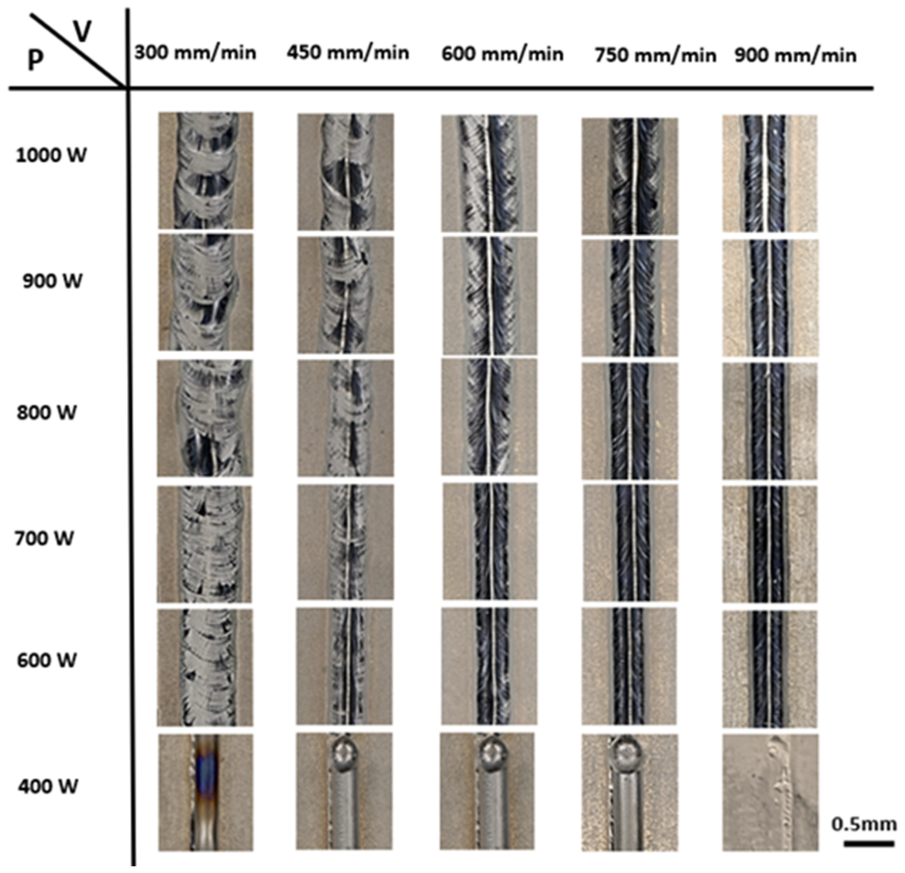
The initial assessment of single-track quality was conducted by analyzing top-view images of the scan tracks. It was observed that both laser power and transverse speed significantly influenced the stability of these tracks. Figure 4 illustrates the morphologies of thirty single tracks deposited at various laser powers (400 to 1000 W) and transverse speeds (300 to 900 mm/min), with detailed specifics outlined in Table 3. Significant variations in size and shape were observed in the single tracks as laser power and transverse speed were changed. At lower laser powers of 400 W and transverse speeds ranging from 300 to 900 mm/min, insufficient heat input prevented the wire from melting and depositing properly, resulting in the deposition of unmelted wire.
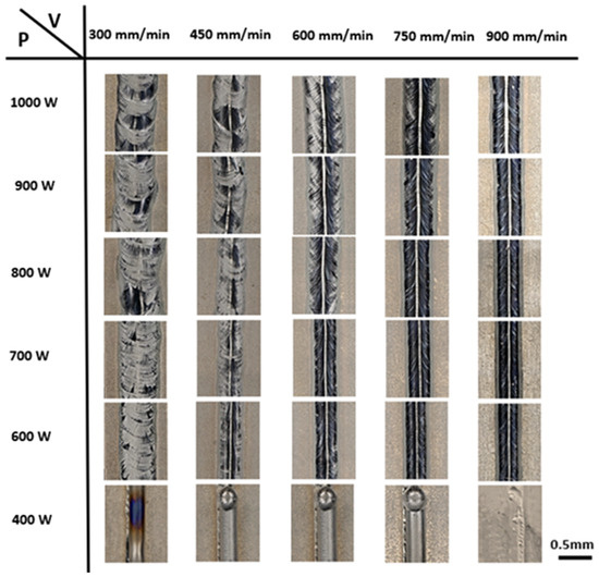
Figure 4.
Top-view images of the NiTi single tracks fabricated with different power and speed.
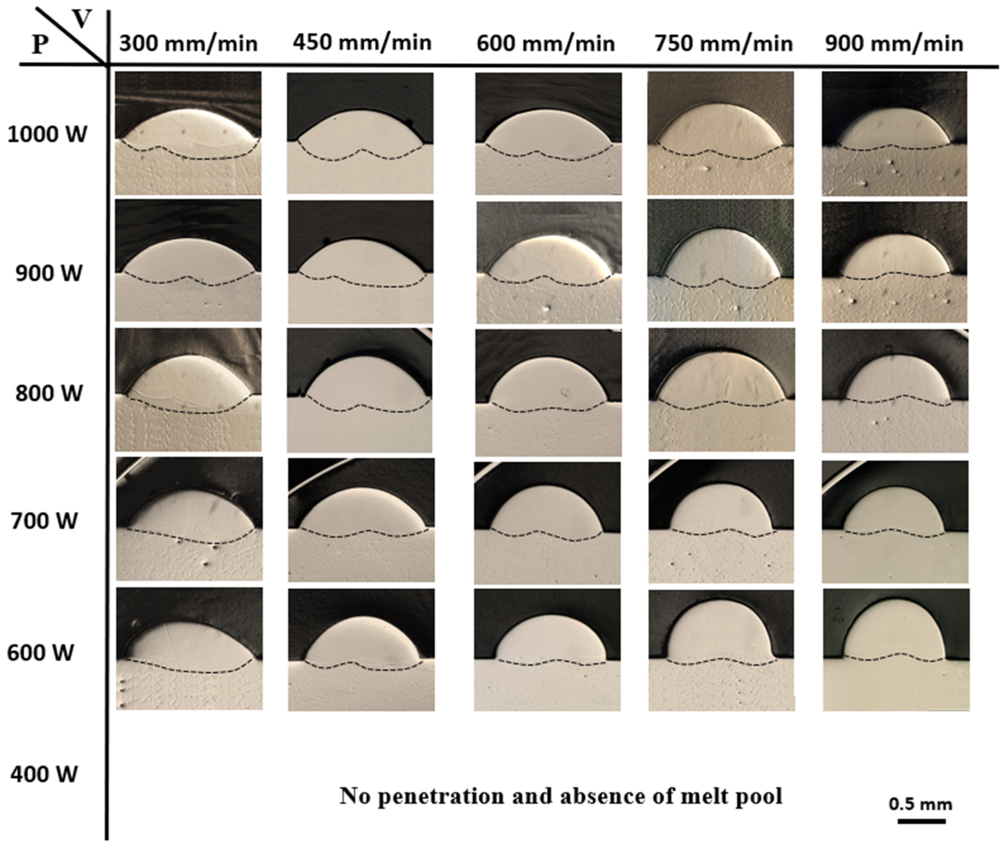
Conversely, increasing the laser power to 600–800 W, along with higher transverse speeds, produced continuous and uniform tracks. Keeping a constant speed of 300 mm/min while increasing the laser power resulted in a thicker single track. Notably, a higher laser power of 1000 W produced wider tracks due to excessive heat input, leading to a rough, wavy surface that indicates over-melting. In contrast, increasing the transverse speed caused the track width to decrease. For example, at a fixed laser power of 600 W, increasing the transverse speed resulted in a narrower track. A higher transverse speed of 900 mm/min, however, demonstrated inadequate penetration due to decreased heat input. As a result, reduced substrate penetration limited the depth of material interaction with the base substrate. Figure 5 illustrates the single-track cross-section, which is essential for evaluating single-track part quality and validating the printability map. During printing, the depth of the melt pool is controlled by a dynamic equilibrium between the heat conduction within the melt pool and the material beneath it [63].
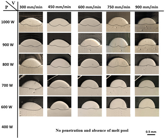
Figure 5.
Cross-section images of the NiTi single tracks fabricated with different power and speed.
It is evident that laser power and transverse speed are the primary processing parameters influencing melt pool geometry in WL-DED. At the minimum power setting of 400 W and speeds ranging from 300 to 900 mm/min, there was insufficient energy to fully melt the wire. Consequently, only melted wire was deposited onto the NiTi plate without proper contact with the substrate, resulting in no penetration and the absence of a melt pool.
Increasing the laser power increased the melt pool depth by intensifying energy absorption and heat input into the wire material [64]. At the maximum laser power of 1000 W, over-melting occurred, resulting in a deeper melt pool. The elevated power level allowed more material to melt into the track, thereby increasing the size of the melt pool. In contrast, when the transverse speed was increased, the melt pool depth decreased, resulting in a shallower melt pool. This occurred due to the decreased heat input and shorter exposure time of the wire material to the laser beam. Consequently, most of the laser energy was absorbed by the wire for melting, leaving less energy transferred to the substrate. As a result, the rapid melting of the wire feedstock and reduced energy transfer to the substrate led to a smaller and shallower melt pool [65]. Single tracks produced with parameter combinations such as 600 W—600 mm/min, 700 W—600 mm/min, 700 W—750 mm/min, 700 W—900 mm/min, and 800 W—900 mm/min exhibit moderate energy input. These combinations result in consistent melt pool shapes with sufficient penetration depth.
Figure 6 illustrates the influence of laser power and transverse speed on the width and depth of the 30 single-track deposits. As shown in Figure 6a, increasing the laser power from 600 W to 1000 W led to a larger deposition width. At a constant transverse speed, increasing the laser power improved the wire’s absorption of laser energy, which facilitated droplet formation and its transition into the molten pool. This, in turn, elevated the molten pool temperature and reduced its solidification rate. As a result, the molten metal spread outward, leading to an increase in the deposit size. For instance, at a constant transverse speed of 750 mm/min, as the laser power was increased from 600 to 1000 W, the width of the melt pool increased from 1.7 mm to 2.49 mm. On the other hand, keeping the laser power constant while increasing the transverse speed led to a reduction in track width. With a laser power of 600 W, the deposit width decreased from 2.38 mm to 1.62 mm as the transverse speed was increased from 300 to 900 mm/min. Figure 6b shows that both laser power and transverse speed significantly influenced the amount of melting and the penetration depth. When energy density was high (i.e., high power, low speed), a greater depth of penetration was observed. Specifically, at lower transverse speeds (300 mm/min) and higher power levels, the melt pool depth increased notably, from 245.07 µm at 600 W to 357.9 µm at 1000 W. Conversely, as the transverse speed increased, both the input energy density to the molten pool and the mass of the fed wire decreased. According to the law of conservation of mass, this led to a reduction in the volume of the molten pool per unit length. As a result, the melt pool depth decreased from 288.76 µm to 36.56 µm as the transverse speed increased from 300 to 900 mm/min at a power level of 700 W.
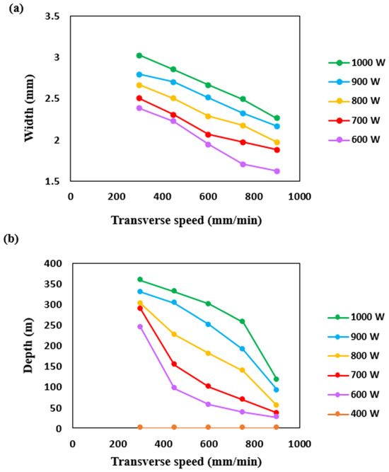
Figure 6.
Effect of laser power and transverse speed on: (a) the width of single tracks and (b) the depth of the melt pool.
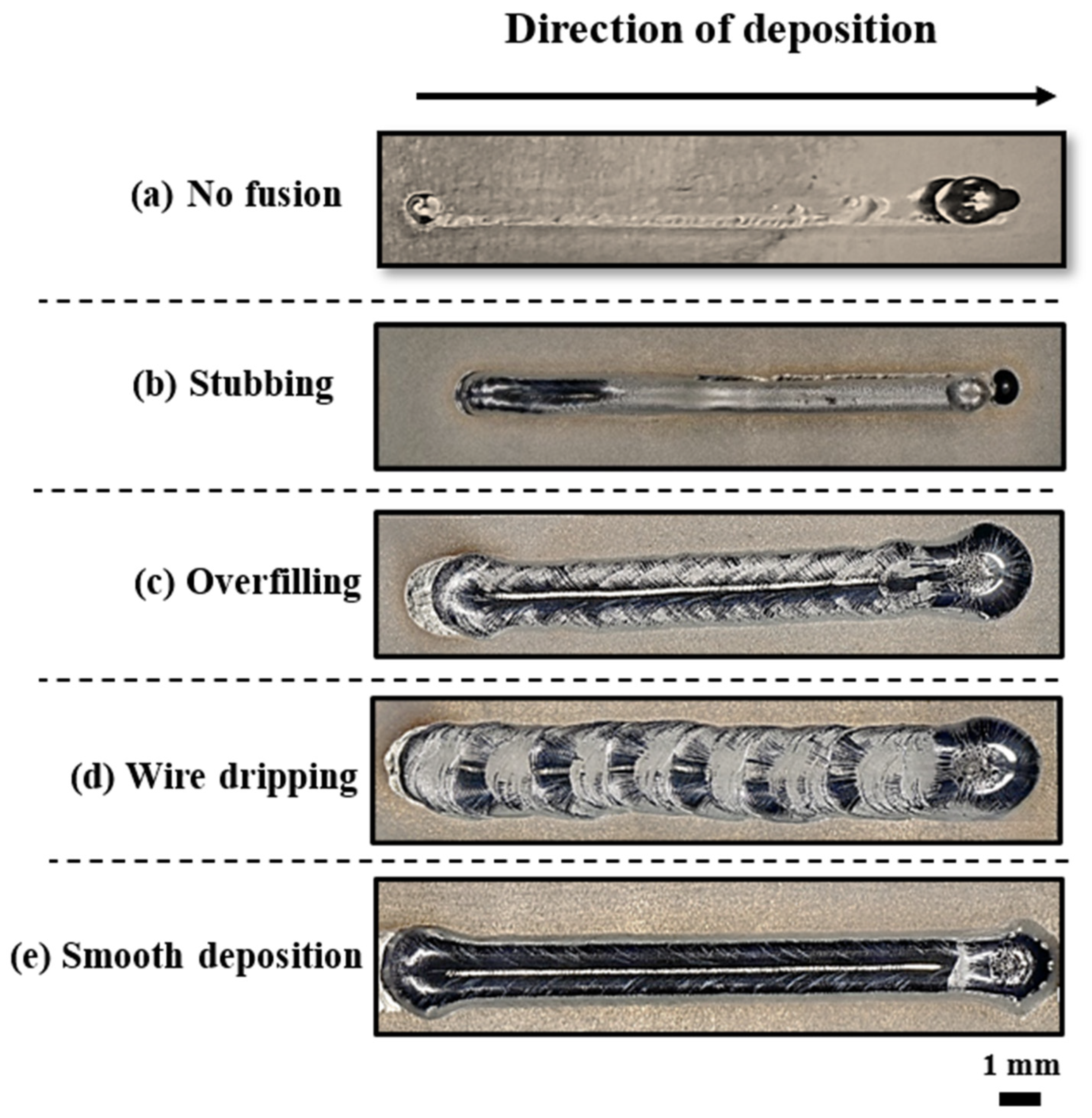
The evaluation of single-track quality was classified as either “acceptable” or “defective”, based on track morphology and melt pool dimension. Five distinct states were identified: a regular and smooth region, and defects including no fusion, stubbing, overfilling, and wire dripping. Figure 7 illustrates top-view optical microscopy (OM) images of single tracks representing these five states, providing a detailed classification of each. No fusion (Figure 7a) occurred due to insufficient energy input, resulting from low laser power and high transverse speed (400 W and 900 mm/min). In these cases, no visible scan track was formed on the substrate, and only heat treatment was applied based on the ablation trace [66]. Stubbing (Figure 7b) occurred in tracks printed with an energy density ranging from 26.66 to 53.33 J/mm (using a low laser power of 400 W and transverse speeds from 450 to 900 mm/min). In these cases, the wire made contact with the base plate surface but did not receive enough energy, resulting in unmelted wire residues within the track [48,67].
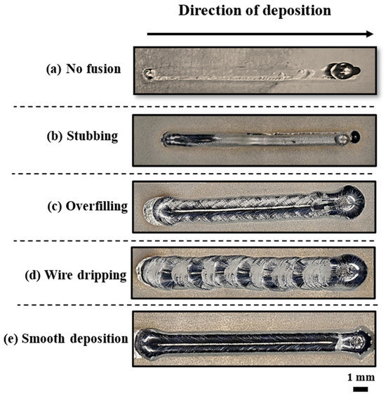
Figure 7.
Top-view images of single tracks withing the five states.
The overfill defect (Figure 7c) occurred when higher laser power settings, particularly within the energy density range of 80–100 J/mm, were used, resulting in increased heat input to the deposition zone. This excess heat caused the material to melt and flow more extensively, leading to deposition beyond the intended track boundaries. While a continuous track remained during overfill, the excess volume of material could negatively affect processability. When the energy density exceeded 100 J/mm, wire dripping occurred [68], as shown in Figure 7d. In this case, the wire was prematurely melted by the laser, causing it to drip above the melt pool and create a rough surface with irregular grooves. This phenomenon was observed at transverse speeds of 300 and 450 mm/min, with power levels ranging from 400 to 1000 W. These uneven surfaces can lead to crack formation, which may serve as stress concentration points under load or deformation [69]. The smooth region, shown in Figure 7e, was characterized by an energy density range from 50 to 70 J/mm. In this region, a continuous transfer of wire into the melt pool was observed, with the wire tip melting at or near the intersection point with the melt pool. These optimal processing conditions, which resulted in smooth wire transfer, were achieved with intermediate laser power values and higher-speed settings (600–800 W power and 600–900 mm/min speed).
3.2. Printability Map
To prevent detrimental defects in builds, it was crucial to define the boundaries of four defect-generation mechanisms on the printability map. This ensures precise identification of the optimal, smooth printable region for WL-DED processing of NiTi. Figure 8 presents the full process window, highlighting both defective and stable regions. Notably, process stability is achieved only within a limited portion of the experimental range. It was found that a minimum laser power of 600 W was necessary to enter the stable zone. Notably, equivalent levels of linear energy density could lead to either defective or successful deposition conditions. For instance, when the linear energy density exceeded 66.67 J/mm, the deposition conditions shifted from defect-prone to successful. However, decreasing both power and transverse speed subsequently led to stubbing. Similarly, maintaining constant power while reducing transverse speed resulted in defective deposition, eventually causing wire dripping. These observations are consistent with findings from previous studies on laser metal wire DED with lateral feeding [67].
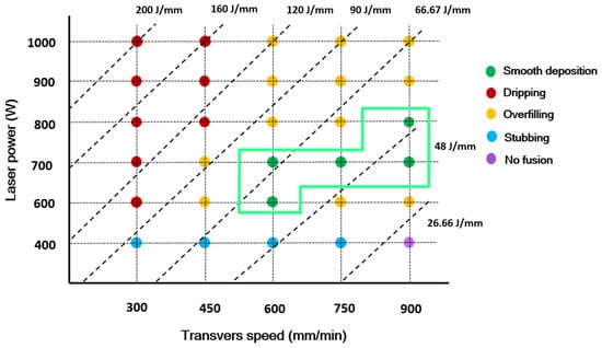
Figure 8.
A process window map of NiTi single tracks illustrating different defects and stable point.
3.3. Analysis of Bulk Cubes
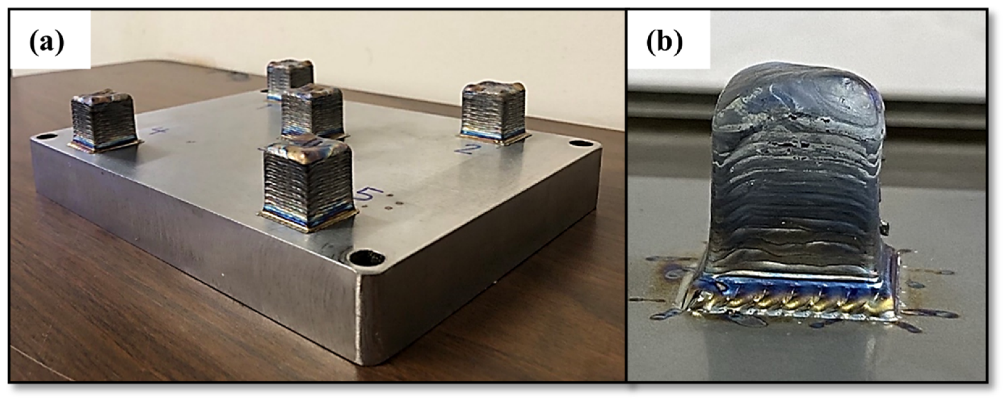
The cubes printed using the optimal single-track processing parameters, as specified in Table 4, exhibited a smooth surface finish and uniform shape with minimal discoloration on both the top and bottom surfaces, as shown in Figure 9a. This discoloration results from varying cooldown rates across the parts; the outer shell experiences more oxidation than the inner areas because it cools more slowly in non-argon shielded regions after each layer is printed. Despite this, the cubes predominantly exhibit a silver color, indicating a low degree of oxidation [70]. Figure 9b illustrates an example of a defective cube printed with a power of 900 W and a transverse speed of 600 mm/min. As observed, the high energy input cause thermal energy to accumulate in the material, leading to overheating. This overheating results in defects such as porosity, high surface roughness, and dimensional inaccuracies [71].
Table 4.
Process parameters used in WL-DED NiTi cube parts.

Figure 9.
(a) Cubes printed with the optimal parameters on the NiTi substrate and (b) imperfection print showing the porosity, surface roughness, and dimensional inaccuracy.
3.3.1. Cross-Sectional Analysis of NiTi Cubes
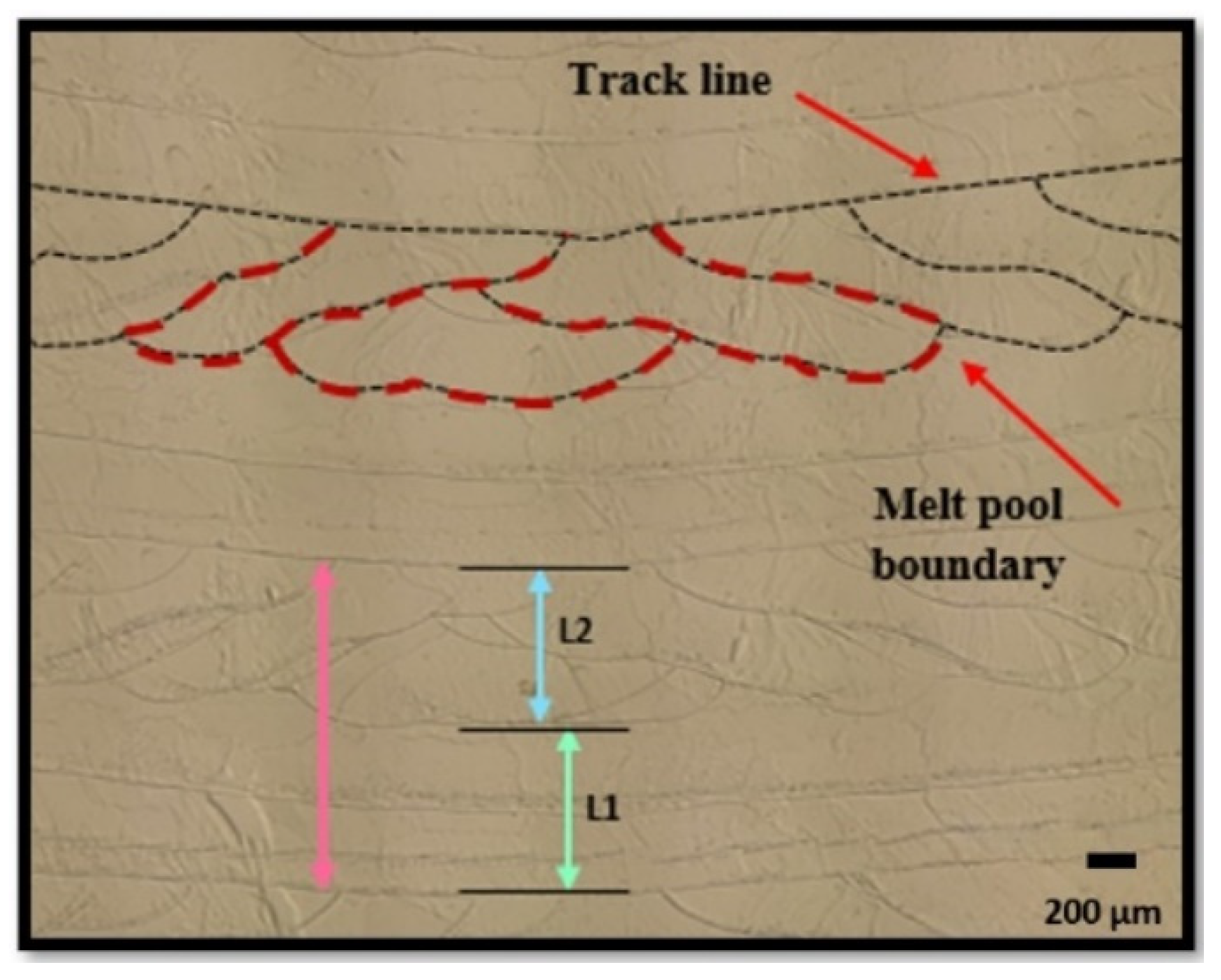
The cross-sectional analysis of the melt pool reveals the track lines and melt pool boundaries, as indicated by the black dashed lines (Figure 10). The cubes were cut parallel to the building direction, providing insights into the melt pool characteristics during layer-by-layer deposition. The printing strategy initiated from the longest diagonal of the square, creating a triangular pattern that progressed towards one side, then returned to the center, continuing in this manner. This pattern is reflected in the shapes of the melt pools, as shown by the dashed red line.
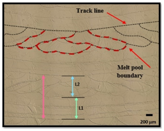
Figure 10.
Cross-sectional images of fabricated NiTi cube, showing the melt pool boundaries and layer thickness.
This cross-sectional view clearly shows the melt pool boundaries. As reported in the literature [72], the melt pool shape in WL-DED can vary depending on the local cooling rate. In this study, due to the inherently rapid cooling rates associated with WL-DED, the melt pool primarily exhibited an elongated oval geometry. The pink lines in the figure represent two consecutive layers and indicate their respective thicknesses. The melt pool for Layer 2 is clearly visible, as it was sectioned parallel to the building direction. However, for Layer 1, which was printed after a 90-degree rotation, the melt pool is not apparent in this cross-section due to the change in orientation.
Effect of Energy Density on the Melt Pool Microstructure
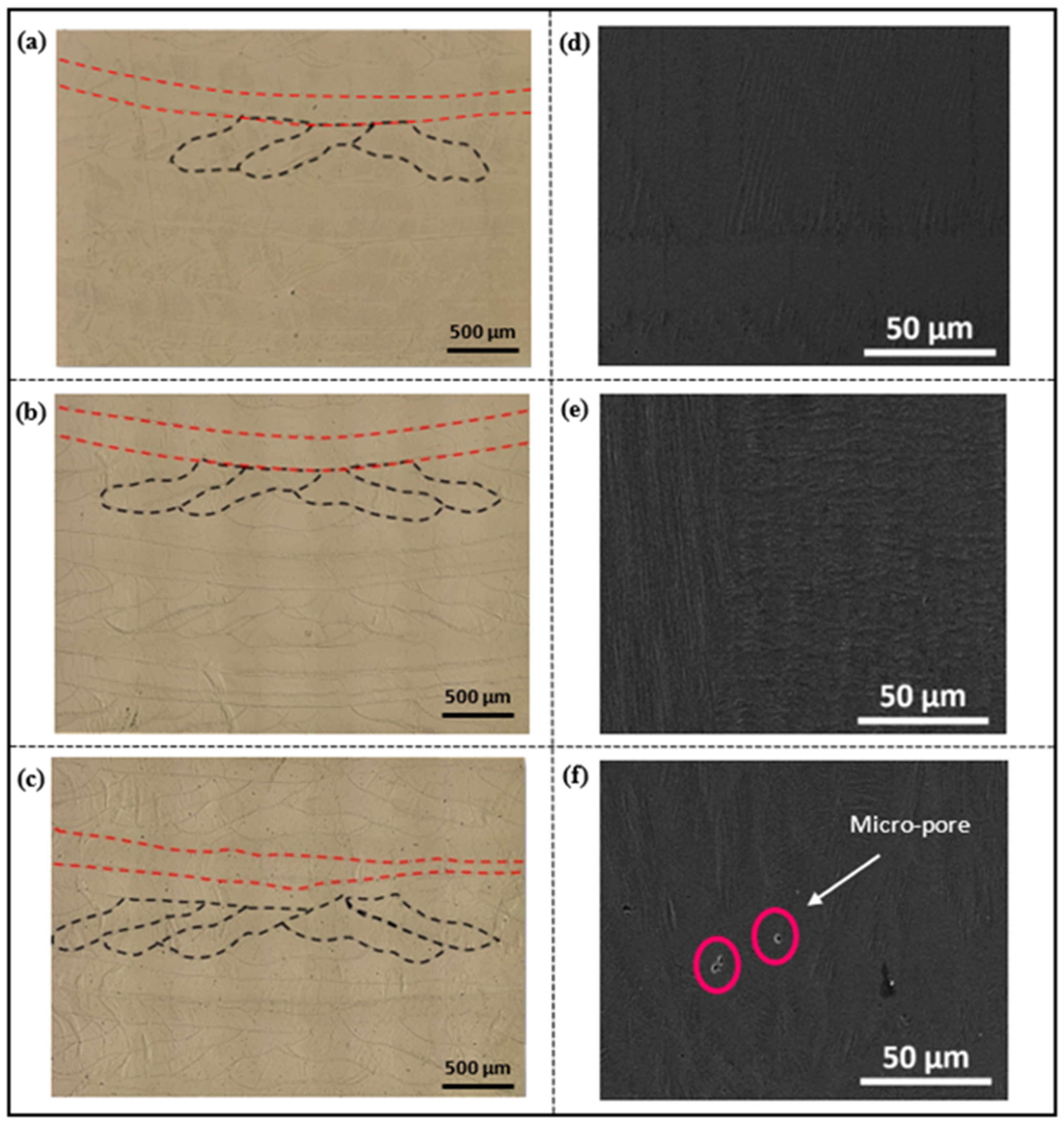
Figure 11a–c present a cross-sectional analysis of the melt pools observed in three fabricated NiTi cubes, each printed with different energy densities ranging from low to high. The cube printed at the energy density of 46.66 J/mm3 exhibited a well-defined and consistent melt pool shape, which was considered optimal for the wire laser-directed energy deposition (DED) process (Figure 11a). The melt pool width was similar to that of the other cubes, ensuring proper fusion between layers. At the intermediate energy density of 56 J/mm3, shown in Figure 11b, the melt pool shape appeared elongated and oval. This elongated shape is typically desirable, as it promotes strong metallurgical bonding and interlayer adhesion.
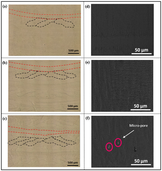
Figure 11.
Cross-sectional views of NiTi cubes at energy densities of (a) 46.66 J/mm3, (b) 56 J/mm3, and (c) 70 J/mm3. SEM micrographs of surface quality at (d) 46.66 J/mm3, (e) 56 J/mm3, and (f) 70 J/mm3.
Increasing the energy density to 70 J/mm3 resulted in a deeper melt pool, indicating a higher degree of melting and material flow (Figure 11c). However, the excessive energy input caused irregular melt pool shapes and boundaries. At high energy densities, excessive melting of the material can lead to instabilities and irregularities in both the melt pool shape and fluid flow behavior. It is important to note that the wire laser DED process involves dynamic and complex interactions between the melt pool, laser, and wire. The stochastic nature of these interactions can introduce randomness and variability in the melt pool characteristics, even at the same energy density [73]. This inherent variability highlights the importance of carefully controlling and optimizing the process parameters to achieve consistent and desirable melt pool geometries. Scanning electron microscopy (SEM) analysis was performed at the center of each cube to evaluate surface quality and identify potential defects in the fabricated NiTi cubes across a range of investigated energy densities. As shown in Figure 11d–f, SEM micrographs of cube printed at energy densities ranging from 46.66 J/mm3 to 56 J/mm3 displayed defect-free surfaces, with no visible pores or cracks. This observation suggests that these energy densities promote optimal melt pool dynamics and material flow, resulting in a well-consolidated and homogeneous surface microstructure. However, at a higher energy density of 70 J/mm3, a distinct transition occurred. The corresponding SEM image (Figure 11f) revealed the formation of micro-pores on the surface of the printed cubes.
3.3.2. Effect of Energy Input on Relative Density of NiTi Cubes
Achieving full part density in additive manufacturing (AM) remains a significant challenge due to the complex interaction between melt pool dynamics and various process parameters that require optimization. In wire laser-directed energy deposition (WL-DED) specifically, porosity formation is a critical concern, as it can significantly impact the mechanical properties of fabricated parts [24]. Two main types of porosity can occur: interlayer porosity and intralayer porosity. Interlayer porosity results from insufficient melting during deposition, often leading to poor fusion between layers [74]. In contrast, intralayer porosity is associated with the use of inert shielding gases during WL-DED [75]. These gases can become trapped within the melt pool, particularly during slower solidification, and typically manifest as spherical pores distributed throughout the layer. Given the negative impact of porosity on part quality, this study focused on the relative density of fabricated NiTi cubes in favorable regions, with particular attention to the effect of energy density. As shown in Figure 12, a clear trend emerges: the highest relative part density was achieved at an energy density of approximately 56 J/mm3. Below this value, there was a slight decrease in density as energy density decreased. However, a more significant drop in density occurred at higher energy densities, particularly at 60 J/mm3. The examination of the cubes printed at high-energy density (60 and 70 J/mm3) revealed the small spherical micropore, as shown in the SEM images in the preceding section. These pores are likely caused by trapped vapor resulting from heat accumulation at these elevated energy densities. Furthermore, the proximity of these high-energy density settings to the defect zone on the established process map suggests that process instabilities may occur at these settings.
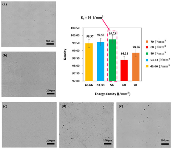
Figure 12.
Relative density of WL-DED NiTi parts as a function of energy density (VED): (a) 46.66 J/mm3, (b) 53.33 J/mm3, (c) 56 J/mm3, (d) 60 J/mm3, and (e) 70 J/mm3.
It is important to note that larger prints may experience even higher overall temperatures due to heat accumulation during the printing process, unlike single-track experiments conducted on a cold substrate. This additional heat can exacerbate the formation of porosity and other defects. Optical microscopy analysis of the cubes revealed that cubes fabricated at lower energy densities (except for those at 60 and 70 J/mm3) exhibited relative densities exceeding 99%. This observation indicates that the processing parameters used below the peak density were effective in producing nearly pore-free NiTi shape memory alloy cubes from wire feedstock. This trend aligns with the findings of Walker et al. [19], who observed a similar pattern in NiTi parts fabricated using LPBF process. The study highlighted a sharp decrease in density below an optimal energy density, followed by a more gradual decline as energy density increased beyond the peak.
3.3.3. Phase Transformation Temperature Analysis
Transformation Temperature Transition from Wire to Cube
The impact of the laser direct energy deposition (DED) process on the phase transformation behavior of NiTi was investigated by comparing the transformation temperatures (TTs) of the as-received NiTi wire feedstock with those of a fabricated, dense NiTi cube. Figure 13 shows the DSC curve, highlighting a notable difference between the TTS of the NiTi wire and the dense cube fabricated with an energy density of 56 J/mm3. The NiTi wire exhibited a two-stage transformation during heating, while the printed cube demonstrated a single-stage transformation in both the heating and cooling cycles. This shift in phase transformation behavior can be attributed to the specific conditions encountered during the DED process. Localized heating from the laser beam caused rapid melting and solidification cycles within the deposited material, altering its microstructure compared to the as-received wire. Additionally, the layer-by-layer deposition characteristics of DED introduced residual stresses and thermal gradients within the printed cube [76]. These internal stresses influenced the material’s phase transformation behavior, as evidenced by the variations observed in the DSC curves.
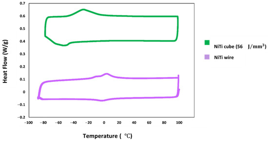
Figure 13.
DSC curve of as-revived NiTi wire and cube fabricated at energy density of 56 J/mm3.
The DSC curve and Table 5 demonstrate that the transformation temperatures (TTs) decrease from the NiTi wire to the fabricated NiTi cube. This shift can be attributed to several factors related to the laser-directed energy deposition (DED) process. A key factor is the formation of secondary phases within the NiTi matrix induced by DED. In particular, the presence of Ti2Ni precipitates played a crucial role in reducing TTs. During DED, localized heating promoted the diffusion of Ti within the melt pool, leading to the formation of Ti2Ni, a Ti-rich phase [77]. This process depleted the surrounding matrix of Ti, resulting in an enrichment of Ni. Ni-rich matrices generally exhibit lower transformation temperatures compared to the stoichiometric NiTi composition.
Table 5.
Transformation temperature of as-revived NiTi wire and cube fabricated at energy density of 56 J/mm3.
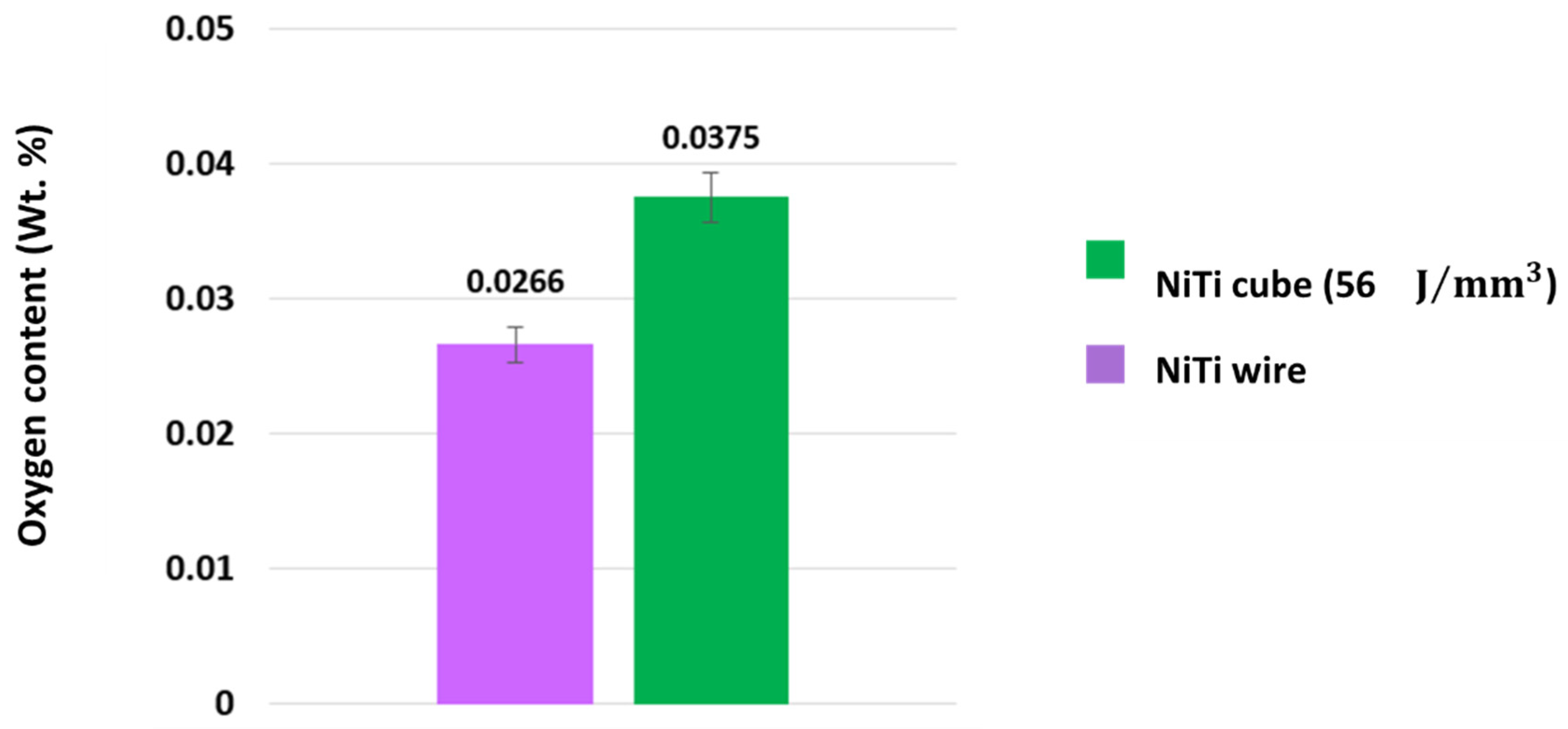
Furthermore, the continuous nature of the DED process may have increased oxygen uptake from the surrounding atmosphere or shielding gas. This elevated oxygen level contributed to the formation of Ti-rich oxides, such as TiO2 or Ni2Ti4Ox. Similar to the formation of Ti2Ni, these oxides consumed Ti from the NiTi matrix, resulting in a higher Ni content and a reduction in transformation temperatures (TTs) [78]. Figure 14 supports these findings, as shown in the ONHp analysis graph. The graph reveals a significant increase in oxygen content, from 266 ppm (0.0266 Wt. %) in the as-received NiTi wire to 375 ppm (0.0375 Wt. %) in the fabricated NiTi cube. This increase in oxygen content correlates with the enhanced formation of Ti-rich oxides during the DED process.
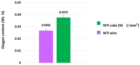
Figure 14.
Oxygen pick-up of the wire and dense cube obtained from ONHp analyzer.
Effect of Energy Density on Transformation Temperature of Cubes
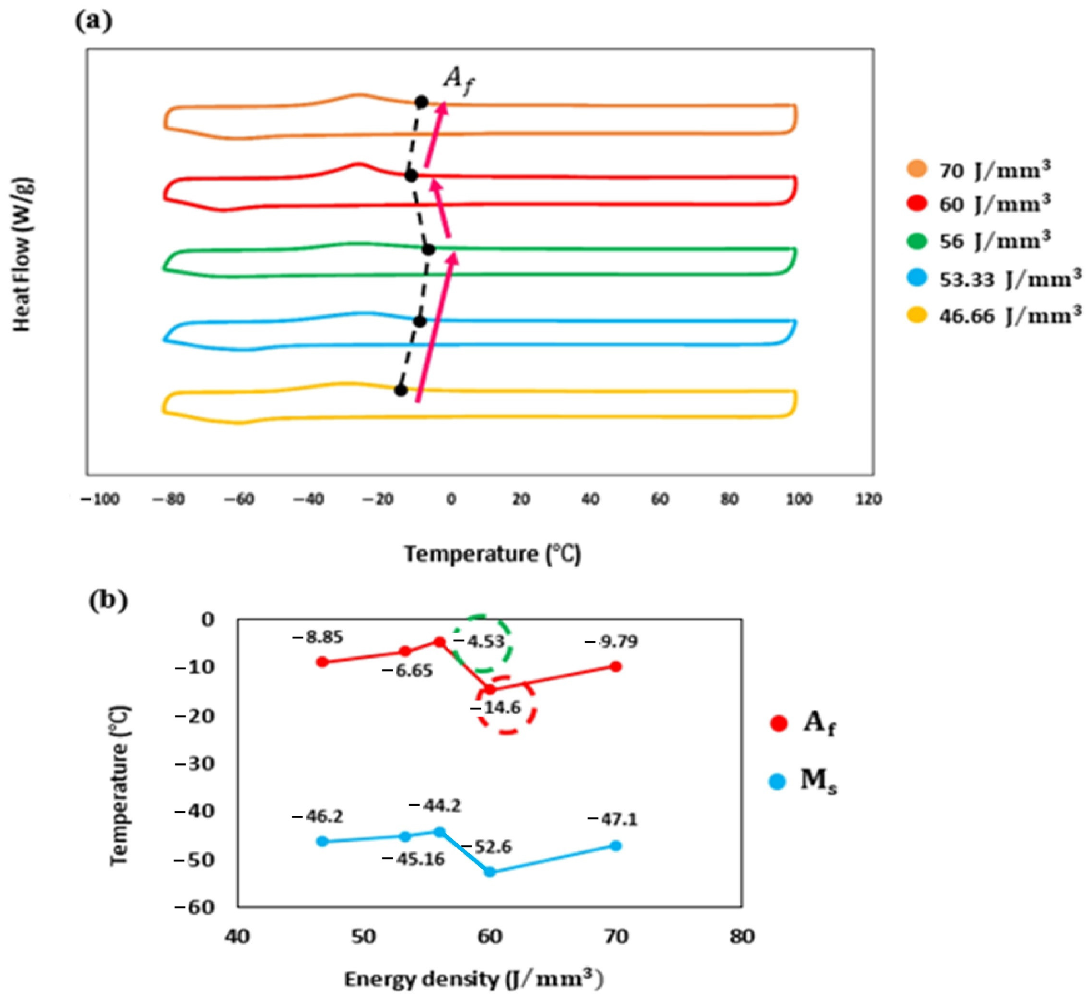
Figure 15 illustrates the transformation temperatures (TTs) of 3D-printed NiTi cubes across a range of energy densities, as determined from curves. The investigation covered an energy density range of 46.66 to 70 J/mm3. Initially, an increase in energy density from 46.66 to 56 J/mm3 resulted in a rise in TTs (Figure 15a). This increase can be attributed to two primary factors. First, during laser processing, Ni evaporates at a faster rate than Ti, leading to a relative depletion of Ni and a shift towards a Ti-rich composition [79,80], which typically increases the TTs in NiTi alloys. Second, higher processing temperatures associated with elevated energy density promote the formation of Ni-rich phases, such as Ni4Ti3, Ni3Ti2, and Ni3Ti. These precipitates deplete the Ni content in the matrix, thereby increasing TTs. However, when the energy density was increased from 56 to 60 J/mm3, a decrease in TTs (Af (°C)) was observed, with a shift of approximately 10 °C from −4.53 °C to −14.6 °C (Figure 15b). This reduction in transformation temperatures is primarily due to increased oxygen absorption during the printing process and the evaporation of Ni. The increase oxygen pickup offsets the decrease in Ni content in the matrix [81].
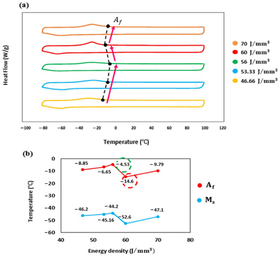
Figure 15.
(a) DSC curves of the fabricated cube across a range of energy densities from low to high and (b) transformation temperatures (Af and Ms) of the fabricated cube.
As illustrated in Figure 16, an energy density of 60 J/mm3 resulted in an oxygen content of 436 ppm (0.0436 Wt. %) compared to 375 ppm (0.0375 Wt. %) at 56 J/mm3. The increased oxygen content promoted the formation of Ti-rich oxides, such as TiO2 or Ni2Ti4Ox, which consume Ti from the NiTi matrix, leading to a decrease in TTs. However, at the highest energy density of 70 J/mm3, a slight increase in TTs is observed. This behavior can be attributed to reduced oxygen pickup and lower degree of Ni depletion at this energy density.
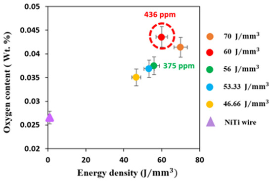
Figure 16.
Oxygen pick-up of the fabricated cubes with different energy density.
3.3.4. Hardness Evaluation of Fabricated NiTi Cubes
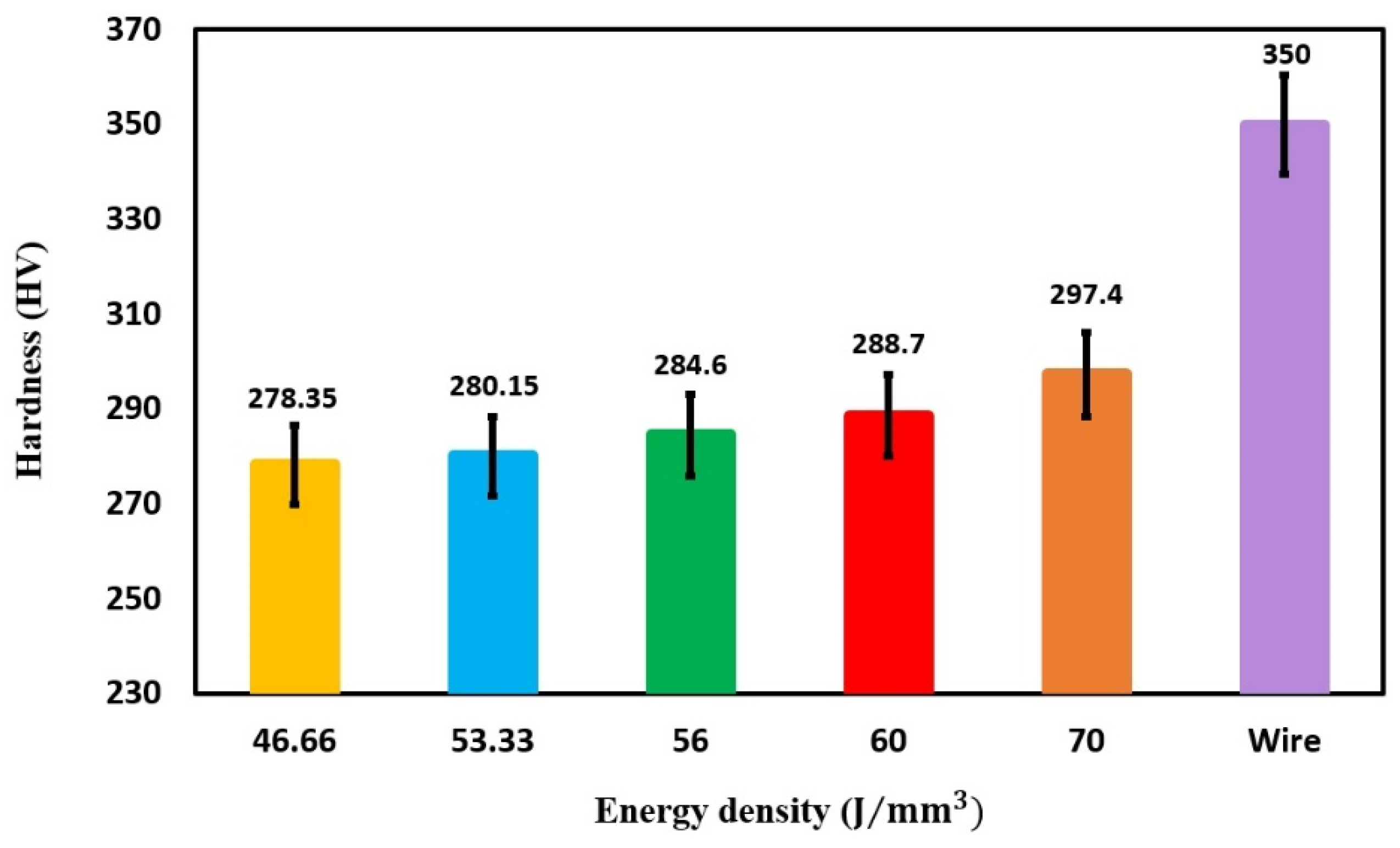
The hardness analysis of the fabricated NiTi cubes, shown in Figure 17, reveals that increasing the energy density enhances the material’s hardness. This phenomenon aligns with the findings from Saedi et al. [82] on Ni-rich NiTi alloys, which observed a similar effect. The likely explanation for this behavior is that higher energy density leads to greater evaporation of nickel during the laser-based additive manufacturing process. Since Ti is inherently harder than Ni, the higher Ti content resulting from the loss of Ni likely contributes to the observed increase in hardness at higher energy density. It is important to note that the phase transformation study indicated that all fabricated samples remain fully austenitic at room temperature. Therefore, variations in energy density did not significantly affect their phase behavior at room temperature, which aligns with observed trends in phase transformation.

Figure 17.
The variation in hardness as a function of energy level.
The phase transformation behavior of the as-received NiTi wire differs significantly from those observed in additively manufactured (AM) samples. The cold-drawn NiTi wire exhibited a hardness of approximately 350 HV, primarily due to work hardening induced by the 40–50% cold work during wire drawing. In contrast, the printed NiTi cubes, which did not undergo the cold working process, displayed a lower hardness of around 290 HV. Furthermore, the localized heat input during from the laser during additive manufacturing acts as a form of localized heat treatment, promoting recrystallization and relieving residual stresses induced by wire cold working [83]. These processes of recrystallization and stress relief contribute to the lower hardness observed in the printed NiTi cubes compared to the cold-worked wire.
4. Conclusions
This study presented a novel method for fabricating NiTi shape memory alloy components through wire laser-directed energy deposition (WL-DED). By optimizing the WL-DED parameters, it effectively addresses a critical gap in the field, facilitating the production of high-quality NiTi parts with minimal defects. A comprehensive process map for WL-DED of NiTi was established using oxide-free Ni55.94Ti (Wt. %) wire with a diameter of 1.14 mm. Through single-track experiments with varying laser power (400–1000 W) and transverse speed (300–900 mm/min), valuable insights were gained into the relationship between processing parameters and part quality. This innovative method provides a solution to the challenges of producing large, complex NiTi components essential for various industrial applications.
The key findings and contributions of this research include the following:
- The single-track study found that laser power between 600 W and 800 W, combined with transverse speeds ranging from 600 mm/min to 900 mm/min, produced the optimal results. These parameters corresponded to an energy density range of 46.66–70 J/mm3, offering a valuable guideline for future NiTi fabrication using WL-DED.
- The cube study demonstrated that lower to intermediate energy densities (46.66 to 56 J/mm3) produced superior results, achieving relative densities exceeding 98%, with some samples surpassing 99%, and favorable phase transformation temperatures for Nickel-Titanium (NiTi) components. In contrast, high energy densities resulted in uneven surfaces, while low energy densities caused discontinuous melts, both of which adversely affected the quality of the parts produced.
- A correlation between increasing energy density and hardness was observed, with higher energy densities leading to greater nickel evaporation and a relative increase in titanium content. The printed NiTi cubes exhibited a hardness of approximately 290 HV, lower than the 350 HV of cold-drawn NiTi wire, due to the absence of work hardening and the effects of localized heat treatment during laser processing.
- High-quality NiTi parts with minimal defects were successfully produced, addressing challenges in manufacturing large and complex components. This advancement shows great potential for industries such as biomedical, aerospace, and civil engineering, particularly for applications like seismic dampers for energy dissipation, which could enhance structural resilience in earthquake-prone areas.
These findings addressed the growing demand for precise shape memory and superelastic materials, offering a method for creating functional NiTi components and expanding their potential applications across various industries.
Author Contributions
Conceptualization, H.D.; Formal analysis, H.D.; Investigation, H.D. and M.P.; Methodology, H.D., N.T.A., M.P. and M.S.; Project administration, M.E.; Supervision, B.P. and M.E.; Validation, H.D.; Visualization, H.D. and B.P.; Writing—original draft, H.D. and N.T.A.; Writing—review and editing, B.P. and M.E. All authors have read and agreed to the published version of the manuscript.
Funding
We acknowledge the financial support of IBASE/OSD to the US Department of Energy, OSD under contract DE-DE-AC05–00OR22725 with UT Battelle LLC and performed in partiality at the Oak Ridge National Laboratory’s Manufacturing Demonstration Facility, an Office of Energy Efficiency and Renewable Energy user facility.
Data Availability Statement
The data presented in this study are available on request from the corresponding author.
Acknowledgments
The authors are thankful for the financial support of Oak Ridge National Laboratory. Special thanks are extended to Fort Wayne Metal, particularly Jenica Kolhoff, Senior Applications Engineer, for their generous support and collaboration during the experimental phases. I am also grateful to the Meltio support team, especially Jesús Rodriguez, for their assistance throughout this study.
Conflicts of Interest
The authors declare no conflicts of interest.
References
- Liu, Y.; Xie, Z.; Jan, V.H.; Luc, D. Deformation of shape memory alloys associated with twinned domain re-configurations. Mater. Sci. Eng. A 1999, 273, 679–684. [Google Scholar] [CrossRef]
- McNANEY, J.M.; Valentina, I.; Jung, Y.; Panayiotis, P.; Ritchie, R.O. An experimental study of the superelastic effect in a shape-memory Nitinol alloy under biaxial loading. Mech. Mater. 2003, 35, 969–986. [Google Scholar] [CrossRef]
- Bruneau, M.; Chang, S.E.; Eguchi, R.T.; Lee, G.C.; O’Rourke, T.D.; Reinhorn, A.M.; Shinozuka, M.; Tierney, K.; Wallace, W.A.; Von Winterfeldt, D. A framework to quantitatively assess and enhance the seismic resilience of communities. Earthq. Spectra 2003, 19, 733–752. [Google Scholar] [CrossRef]
- Saadat, S.; Salichs, J.; Mohammad, N.; Hou, Z.; Davoodi, H.; Isa, B.O.; Suzuki, Y.; Masuda, A. An overview of vibration and seismic applications of NiTi shape memory alloy. Smart Mater. Struct. 2002, 11, 218. [Google Scholar] [CrossRef]
- Elahinia, M.H.; Mahdi, H.; Majid, T.; Sarit, B.B. Manufacturing and processing of NiTi implants: A review. Prog. Mater. Sci. 2012, 57, 911–946. [Google Scholar] [CrossRef]
- Nematollahi, M.; Keyvan, S.; Parisa, B.; Mohammad, E. Functionally graded NiTi shape memory alloy: Selective laser melting fabrication and multi-scale characterization. Mater. Lett. 2021, 292, 129648. [Google Scholar] [CrossRef]
- Pelton, A.R.; Russell, S.M.; DiCello, J. The physical metallurgy of nitinol for medical applications. Jom 2003, 55, 33–37. [Google Scholar] [CrossRef]
- Haberland, C.; Mohammad, E.; Jason, W.; Horst, M. Visions, concepts and strategies for smart nitinol actuators and complex nitinol structures produced by additive manufacturing. In Smart Materials, Adaptive Structures and Intelligent Systems; American Society of Mechanical Engineers: New York City, NY, USA, 2013. [Google Scholar]
- Haberland, C.; Mohammad, E.; Jason, M.W.; Horst, M.; Jan, F. On the development of high quality NiTi shape memory and pseudoelastic parts by additive manufacturing. Smart Mater. Struct. 2014, 23, 104002. [Google Scholar] [CrossRef]
- Shayesteh Moghaddam, N.; Mohsen, T.A.; Amirhesam, A.; Christoph, H.; Scott, H.; Michael, M.; Mohammad, E.; David, D. Metals for bone implants: Safety, design, and efficacy. Biomanufacturing Rev. 2016, 1, 1. [Google Scholar] [CrossRef]
- Saedi, S.; Turabi, A.S.; Andani, M.T.; Moghaddam, N.S.; Elahinia, M.; Karaca, H.E. Texture, aging, and superelasticity of selective laser melting fabricated Ni-rich NiTi alloys. Mater. Sci. Eng. A 2017, 686, 1–10. [Google Scholar] [CrossRef]
- Hamilton, R.F.; Bimber, B.A.; Andani, M.T.; Elahinia, M. Multi-scale shape memory effect recovery in NiTi alloys additive manufactured by selective laser melting and laser directed energy deposition. J. Mater. Process. Technol. 2017, 250, 55–64. [Google Scholar] [CrossRef]
- Saedi, S.; Saghaian, S.E.; Jahadakbar, A.; Moghaddam, N.S.; Andani, M.T.; Saghaian, S.M.; Lu, Y.C.; Elahinia, M.; Karaca, H.E. Shape memory response of porous NiTi shape memory alloys fabricated by selective laser melting. J. Mater. Sci. Mater. Med. 2018, 29, 40. [Google Scholar] [CrossRef]
- Jahadakbar, A.; Nematollahi, M.; Safaei, K.; Bayati, P.; Giri, G.; Dabbaghi, H.; Dean, D.; Elahinia, M. Design, modeling, additive manufacturing, and polishing of stiffness-modulated porous nitinol bone fixation plates followed by thermomechanical and composition analysis. Metals 2020, 10, 151. [Google Scholar] [CrossRef]
- Bayati, P.; Safaei, K.; Nematollahi, M.; Jahadakbar, A.; Yadollahi, A.; Mahtabi, M.; Elahinia, M. Toward understanding the effect of remelting on the additively manufactured NiTi. Int. J. Adv. Manuf. Technol. 2021, 112, 347–360. [Google Scholar] [CrossRef]
- Nematollahi, M.; Saghaian, S.E.; Safaei, K.; Bayati, P.; Bassani, P.; Biffi, C.; Tuissi, A.; Karaca, H.; Elahinia, M. Building orientation-structure-property in laser powder bed fusion of NiTi shape memory alloy. J. Alloys Compd. 2021, 873, 159791. [Google Scholar] [CrossRef]
- Safaei, K.; Nematollahi, M.; Bayati, P.; Dabbaghi, H.; Benafan, O.; Elahinia, M. Torsional behavior and microstructure characterization of additively manufactured NiTi shape memory alloy tubes. Eng. Struct. 2021, 226, 111383. [Google Scholar] [CrossRef]
- Safaei, K.; Abedi, H.; Nematollahi, M.; Kordizadeh, F.; Dabbaghi, H.; Bayati, P.; Javanbakht, R.; Jahadakbar, A.; Elahinia, M.; Poorganji, B. Additive manufacturing of NiTi shape memory alloy for biomedical applications: Review of the LPBF process ecosystem. Jom 2021, 73, 3771–3786. [Google Scholar] [CrossRef]
- Walker, J.M.; Haberland, C.; Andani, M.T.; Karaca, H.E.; Dean, D.; Elahinia, M. Process development and characterization of additively manufactured nickel–titanium shape memory parts. J. Intell. Mater. Syst. Struct. 2016, 27, 2653–2660. [Google Scholar] [CrossRef]
- Ahn, D.-G. Directed energy deposition (DED) process: State of the art. Int. J. Precis. Eng. Manuf.-Green Technol. 2021, 8, 703–742. [Google Scholar] [CrossRef]
- Parvizi, S.; Hashemi, S.M.; Asgarinia, F.; Nematollahi, M.; Elahinia, M. Effective parameters on the final properties of NiTi-based alloys manufactured by powder metallurgy methods: A review. Prog. Mater. Sci. 2021, 117, 100739. [Google Scholar] [CrossRef]
- Bagheri, A.; Yadollahi, A.; Mahtabi, M.J.; Paudel, Y.; Vance, E.; Shamsaei, N.; Horstemeyer, M.F. Microstructure-based MultiStage fatigue modeling of NiTi alloy fabricated via direct energy deposition (DED). J. Mater. Eng. Perform. 2022, 31, 4761–4775. [Google Scholar] [CrossRef]
- Chen, Y.; Zhang, X.; Parvez, M.M.; Liou, F. A review on metallic alloys fabrication using elemental powder blends by laser powder directed energy deposition process. Materials 2020, 13, 3562. [Google Scholar] [CrossRef] [PubMed]
- Dass, A.; Moridi, A. State of the art in directed energy deposition: From additive manufacturing to materials design. Coatings 2019, 9, 418. [Google Scholar] [CrossRef]
- Hwang, T.; Woo, Y.Y.; Han, S.W.; Moon, Y.H. Functionally graded properties in directed-energy-deposition titanium parts. Opt. Laser Technol. 2018, 105, 80–88. [Google Scholar] [CrossRef]
- Feenstra, D.; Banerjee, R.; Fraser, H.L.; Huang, A.; Molotnikov, A.; Birbilis, N. Critical review of the state of the art in multi-material fabrication via directed energy deposition. Curr. Opin. Solid State Mater. Sci. 2021, 25, 100924. [Google Scholar] [CrossRef]
- Ansari, M.; Jabari, E.; Toyserkani, E. Opportunities and challenges in additive manufacturing of functionally graded metallic materials via powder-fed laser directed energy deposition: A review. J. Mater. Process. Technol. 2021, 294, 117117. [Google Scholar] [CrossRef]
- Kumar, S.; Marandi, L.; Balla, V.K.; Bysakh, S.; Piorunek, D.; Eggeler, G.; Das, M.; Sen, I. Microstructure–Property correlations for additively manufactured NiTi based shape memory alloys. Materialia 2019, 8, 100456. [Google Scholar] [CrossRef]
- Baran, A.; Polanski, M. Microstructure and properties of LENS (laser engineered net shaping) manufactured Ni-Ti shape memory alloy. J. Alloys Compd. 2018, 750, 863–870. [Google Scholar] [CrossRef]
- Zheng, D.; Li, R.-D.; Yuan, T.-C.; Xiong, Y.; Song, B.; Wang, J.-X.; Su, Y.-D. Microstructure and mechanical property of additively manufactured NiTi alloys: A comparison between selective laser melting and directed energy deposition. J. Cent. South Univ. 2021, 28, 1028–1042. [Google Scholar] [CrossRef]
- Derekar, K. A review of wire arc additive manufacturing and advances in wire arc additive manufacturing of aluminium. Mater. Sci. Technol. 2018, 34, 895–916. [Google Scholar] [CrossRef]
- Li, Z.; Sui, S.; Ma, X.; Tan, H.; Zhong, C.; Bi, G.; Clare, A.T.; Gasser, A.; Chen, J. High deposition rate powder-and wire-based laser directed energy deposition of metallic materials: A review. Int. J. Mach. Tools Manuf. 2022, 181, 103942. [Google Scholar] [CrossRef]
- Svetlizky, D.; Zheng, B.; Vyatskikh, A.; Das, M.; Bose, S.; Bandyopadhyay, A.; Schoenung, J.M.; Lavernia, E.J.; Eliaz, N. Laser-based directed energy deposition (DED-LB) of advanced materials. Mater. Sci. Eng. A 2022, 840, 142967. [Google Scholar] [CrossRef]
- Wang, Y.; Chen, X.; Konovalov, S. Additive manufacturing based on welding arc: A low-cost method. J. Surf. Investig. X-Ray Synchrotron Neutron Tech. 2017, 11, 1317–1328. [Google Scholar] [CrossRef]
- Lu, T.; Liu, C.; Li, Z.; Wu, Q.; Wang, J.; Xu, T.; Liu, J.; Wang, H.; Ma, S. Hot-wire arc additive manufacturing Ti–6.5 Al–2Zr–1Mo–1V titanium alloy: Pore characterization, microstructural evolution, and mechanical properties. J. Alloys Compd. 2020, 817, 153334. [Google Scholar] [CrossRef]
- Chaturvedi, M.; Scutelnicu, E.; Rusu, C.C.; Mistodie, L.R.; Mihailescu, D.; Subbiah, A.V. Wire arc additive manufacturing: Review on recent findings and challenges in industrial applications and materials characterization. Metals 2021, 11, 939. [Google Scholar] [CrossRef]
- Yu, L.; Chen, K.; Zhang, Y.; Liu, J.; Yang, L.; Shi, Y. Microstructures and mechanical properties of NiTi shape memory alloys fabricated by wire arc additive manufacturing. J. Alloys Compd. 2022, 892, 162193. [Google Scholar] [CrossRef]
- Singh, S.; Resnina, N.; Belyaev, S.; Jinoop, A.N.; Shukla, A.; Palani, I.A.; Paul, C.P.; Bindra, K.S. Investigations on NiTi shape memory alloy thin wall structures through laser marking assisted wire arc based additive manufacturing. J. Manuf. Process. 2021, 66, 70–80. [Google Scholar] [CrossRef]
- Shen, C.; Reid, M.; Liss, K.-D.; Hua, X.; Pan, Z.; Mou, G.; Huang, Y.; Li, H. In-situ neutron diffraction study on the high temperature thermal phase evolution of wire-arc additively manufactured Ni53Ti47 binary alloy. J. Alloys Compd. 2020, 843, 156020. [Google Scholar] [CrossRef]
- Wang, J.; Pan, Z.; Wang, Y.; Wang, L.; Su, L.; Cuiuri, D.; Zhao, Y.; Li, H. Evolution of crystallographic orientation, precipitation, phase transformation and mechanical properties realized by enhancing deposition current for dual-wire arc additive manufactured Ni-rich NiTi alloy. Addit. Manuf. 2020, 34, 101240. [Google Scholar] [CrossRef]
- Liu, G.; Zhou, S.; Lin, P.; Zong, X.; Chen, Z.; Zhang, Z.; Ren, L. Analysis of microstructure, mechanical properties, and wear performance of NiTi alloy fabricated by cold metal transfer based wire arc additive manufacturing. J. Mater. Res. Technol. 2022, 20, 246–259. [Google Scholar] [CrossRef]
- Dhinakaran, V.; Ajith, J.; Fahmidha, A.F.Y.; Jagadeesha, T.; Sathish, T.; Stalin, B. Wire Arc Additive Manufacturing (WAAM) process of nickel based superalloys–A review. Mater. Today Proc. 2020, 21, 920–925. [Google Scholar] [CrossRef]
- Baufeld, B.; Widdison, R.; Dutilleul, T. Wire based electron beam additive manufacturing. In Proceedings of the 70th IIW Assembly and International Conference, Shanghai, China, 25–30 June 2017. [Google Scholar]
- Zapata, A.; Bernauer, C.; Stadter, C.; Kolb, C.G.; Zaeh, M.F. Investigation on the cause-effect relationships between the process parameters and the resulting geometric properties for wire-based coaxial laser metal deposition. Metals 2022, 12, 455. [Google Scholar] [CrossRef]
- Elmer, J.W.; Vaja, J.; Carpenter, J.S.; Coughlin, D.R.; Dvornak, M.J.; Hochanadel, P.; Gurung, P.; Johnson, A.; Gibbs, G. Wire-based additive manufacturing of stainless steel components. Weld. J. 2020, 99, 1618196. [Google Scholar] [CrossRef]
- Akbari, M.; Ding, Y.; Kovacevic, R. Process development for a robotized laser wire additive manufacturing. In Proceedings of the International Manufacturing Science and Engineering Conference, Vigo, Pontevedra, Spain, 28–30 June 2017. [Google Scholar]
- Wang, M.; Ventzke, V.; Kashaev, N. Wire-based laser directed energy deposition of AA7075: Effect of process parameters on microstructure and mechanical properties. J. Mater. Res. Technol. 2022, 21, 388–403. [Google Scholar] [CrossRef]
- Motta, M.; Demir, A.G.; Previtali, B. High-speed imaging and process characterization of coaxial laser metal wire deposition. Addit. Manuf. 2018, 22, 497–507. [Google Scholar] [CrossRef]
- Miller, D.A.; Lagoudas, D.C. Influence of cold work and heat treatment on the shape memory effect and plastic strain development of NiTi. Mater. Sci. Eng. A 2001, 308, 161–175. [Google Scholar] [CrossRef]
- Khelfaoui, F.; Guénin, G. Influence of the recovery and recrystallization processes on the martensitic transformation of cold worked equiatomic Ti–Ni alloy. Mater. Sci. Eng. A 2003, 355, 292–298. [Google Scholar] [CrossRef]
- Su, P.; Wu, S. The four-step multiple stage transformation in deformed and annealed Ti49Ni51 shape memory alloy. Acta Mater. 2004, 52, 1117–1122. [Google Scholar] [CrossRef]
- Chang, S.; Wu, S.; Chang, G. Transformation sequence in severely cold-rolled and annealed Ti50Ni50 alloy. Mater. Sci. Eng. A 2006, 438, 509–512. [Google Scholar] [CrossRef]
- Todoroki, T.; Tamura, H. Effect of heat treatment after cold working on the phase transformation in TiNi alloy. Trans. Jpn. Inst. Met. 1987, 28, 83–94. [Google Scholar] [CrossRef]
- Zhu, J.; Wu, H.-H.; Wu, Y.; Wang, H.; Zhang, T.; Xiao, H.; Wang, Y.; Shi, S.-Q. Influence of Ni4Ti3 precipitation on martensitic transformations in NiTi shape memory alloy: R phase transformation. Acta Mater. 2021, 207, 116665. [Google Scholar] [CrossRef]
- Yao, X. An Advanced TEM Study on Quantification of Precipitates in Low Temperature Aged Ni-Ti Shape Memory Alloy. Doctoral Thesis, University of Antwerp, Antwerp, Belgium, 2019. [Google Scholar]
- Xu, B.; Sun, Y.; Yu, C.; Hu, J.; Zhu, J.; Xiong, J.; Kan, Q.; Wang, C.; Wang, Q.; Kang, G. Effect of Ni4Ti3 precipitates on the functional properties of NiTi shape memory alloys: A phase field study. Int. J. Plast. 2024, 177, 103993. [Google Scholar] [CrossRef]
- Chang, S.-H.; Lin, K.-H.; Wu, S.-K. Effects of cold-rolling/aging treatments on the shape memory properties of Ti49.3Ni50.7 shape memory alloy. Materials 2017, 10, 704. [Google Scholar] [CrossRef] [PubMed]
- Chang, S.; Wu, S.; Chang, G. Grain size effect on multiple-stage transformations of a cold-rolled and annealed equiatomic TiNi alloy. Scr. Mater. 2005, 52, 1341–1346. [Google Scholar] [CrossRef]
- Cho, Y.H.; Khan, M.S.; Goodwin, F.E.; Zhou, Y.N. Effect of torch angle and position on bead geometry and joint strength during arc-brazing of DP600. Int. J. Adv. Manuf. Technol. 2022, 121, 543–557. [Google Scholar] [CrossRef]
- Sun, L.; Jiang, F.; Huang, R.; Yuan, D.; Su, Y.; Guo, C.; Wang, J. Investigation on the process window with liner energy density for single-layer parts fabricated by wire and arc additive manufacturing. J. Manuf. Process. 2020, 56, 898–907. [Google Scholar] [CrossRef]
- Bastola, N.; Jahan, M.P.; Rangasamy, N.; Rakurty, C.S. A review of the residual stress generation in metal additive manufacturing: Analysis of cause, measurement, effects, and prevention. Micromachines 2023, 14, 1480. [Google Scholar] [CrossRef] [PubMed]
- Rathor, S.; Kant, R.; Singla, E. Effect of laser energy density on bead characteristics in wire-DED. Sādhanā 2024, 49, 104. [Google Scholar] [CrossRef]
- Piazza, S.; Merrigan, B.; Dowling, D.P.; Celikin, M. The effects of geometry and laser power on the porosity and melt pool formation in additively manufactured 316L stainless steel. Int. J. Adv. Manuf. Technol. 2020, 111, 1457–1470. [Google Scholar] [CrossRef]
- Huang, W.; Chen, S.; Xiao, J.; Jiang, X.; Jia, Y. Laser wire-feed metal additive manufacturing of the Al alloy. Opt. Laser Technol. 2021, 134, 106627. [Google Scholar] [CrossRef]
- Li, B.; Wang, B.; Zhu, G.; Zhang, L.; Lu, B. Low-roughness-surface additive manufacturing of metal-wire feeding with small power. Materials 2021, 14, 4265. [Google Scholar] [CrossRef] [PubMed]
- Shao, J.; Yu, G.; He, X.; Li, S.; Li, Z.; Wang, X. Process maps and optimal processing windows based on three-dimensional morphological characteristics in laser directed energy deposition of Ni-based alloy. Opt. Laser Technol. 2021, 142, 107162. [Google Scholar] [CrossRef]
- Abioye, T.; Folkes, J.; Clare, A. A parametric study of Inconel 625 wire laser deposition. J. Mater. Process. Technol. 2013, 213, 2145–2151. [Google Scholar] [CrossRef]
- Bozeman, S.C.; Isgor, O.B.; Tucker, J.D. Effects of processing conditions on the solidification and heat-affected zone of 309L stainless steel claddings on carbon steel using wire-directed energy deposition. Surf. Coat. Technol. 2022, 444, 128698. [Google Scholar] [CrossRef]
- Kisielewicz, A.; Pandian, K.T.; Sthen, D.; Hagqvist, P.; Bermejo, M.A.V.; Sikström, F.; Ancona, A. Hot-wire laser-directed energy deposition: Process characteristics and benefits of resistive pre-heating of the feedstock wire. Metals 2021, 11, 634. [Google Scholar] [CrossRef]
- Jurić, I.; Garašić, I.; Bušić, M.; Kožuh, Z. Influence of shielding gas composition on structure and mechanical properties of wire and arc additive manufactured Inconel 625. Jom 2019, 71, 703–708. [Google Scholar] [CrossRef]
- Bieg, F.; Scheider, D.; Kledwig, C.; Maucher, C.; Möhring, H.-C.; Reisacher, M. Development of a laser preheating concept for directed energy deposition. J. Laser Appl. 2023, 35, 042052. [Google Scholar] [CrossRef]
- Akbari, M.; Kovacevic, R. An investigation on mechanical and microstructural properties of 316LSi parts fabricated by a robotized laser/wire direct metal deposition system. Addit. Manuf. 2018, 23, 487–497. [Google Scholar] [CrossRef]
- Abadi, S.N.R.; Mi, Y.; Kisielewicz, A.; Sikström, F.; Choquet, I. Influence of laser-wire interaction on heat and metal transfer in directed energy deposition. Int. J. Heat Mass Transf. 2023, 205, 123894. [Google Scholar] [CrossRef]
- Bassis, M.; Kotliar, A.; Koltiar, R.; Ron, T.; Leon, A.; Shirizly, A.; Aghion, E. The effect of a slow strain rate on the stress corrosion resistance of austenitic stainless steel produced by the wire laser additive manufacturing process. Metals 2021, 11, 1930. [Google Scholar] [CrossRef]
- Bassis, M.; Ron, T.; Leon, A.; Kotliar, A.; Kotliar, R.; Shirizly, A.; Aghion, E. The Influence of Intralayer Porosity and Phase Transition on Corrosion Fatigue of Additively Manufactured 316L Stainless Steel Obtained by Direct Energy Deposition Process. Materials 2022, 15, 5481. [Google Scholar] [CrossRef]
- Saedi, S.; Turabi, A.S.; Andani, M.T.; Haberland, C.; Karaca, H.; Elahinia, M. The influence of heat treatment on the thermomechanical response of Ni-rich NiTi alloys manufactured by selective laser melting. J. Alloys Compd. 2016, 677, 204–210. [Google Scholar] [CrossRef]
- Otsuka, K.; Ren, X. Physical metallurgy of Ti–Ni-based shape memory alloys. Prog. Mater. Sci. 2005, 50, 511–678. [Google Scholar] [CrossRef]
- Zhang, B.; Chen, J.; Coddet, C. Microstructure and transformation behavior of in-situ shape memory alloys by selective laser melting Ti–Ni mixed powder. J. Mater. Sci. Technol. 2013, 29, 863–867. [Google Scholar] [CrossRef]
- Andani, M.T.; Haberland, C.; Walker, J.; Elahinia, M. An investigation of effective process parameters on phase transformation temperature of nitinol manufactured by selective laser melting. In Smart Materials, Adaptive Structures and Intelligent Systems; American Society of Mechanical Engineers: New York City, NY, USA, 2014. [Google Scholar]
- Bormann, T.; Schumacher, R.; Müller, B.; Mertmann, M.; De Wild, M. Tailoring selective laser melting process parameters for NiTi implants. J. Mater. Eng. Perform. 2012, 21, 2519–2524. [Google Scholar] [CrossRef]
- Wei, S.; Zhang, J.; Zhang, L.; Zhang, Y.; Song, B.; Wang, X.; Fan, J.; Liu, Q.; Shi, Y. Laser powder bed fusion additive manufacturing of NiTi shape memory alloys: A review. Int. J. Extrem. Manuf. 2023, 5, 032001. [Google Scholar] [CrossRef]
- Saedi, S.; Moghaddam, N.S.; Amerinatanzi, A.; Elahinia, M.; Karaca, H.E. On the effects of selective laser melting process parameters on microstructure and thermomechanical response of Ni-rich NiTi. Acta Mater. 2018, 144, 552–560. [Google Scholar] [CrossRef]
- Mahmud, A.S.; Wu, Z.; Yang, H.; Liu, Y. Effect of cold work and partial annealing on thermomechanical behaviour of Ti-50.5 at% Ni. Shape Mem. Superelasticity 2017, 3, 57–66. [Google Scholar] [CrossRef]


Disclaimer/Publisher’s Note: The statements, opinions and data contained in all publications are solely those of the individual author(s) and contributor(s) and not of MDPI and/or the editor(s). MDPI and/or the editor(s) disclaim responsibility for any injury to people or property resulting from any ideas, methods, instructions or products referred to in the content. |
© 2025 by the authors. Licensee MDPI, Basel, Switzerland. This article is an open access article distributed under the terms and conditions of the Creative Commons Attribution (CC BY) license (https://creativecommons.org/licenses/by/4.0/).